Article

Stress Measurement and Analysis of Structural Parameters of Flat Arm Tower Crane Under Different Working Conditions

1
School of Civil Engineering and Communication, North China University of Water Resources and Electric Power, Zhengzhou 450045, China
2
China Construction Third Engineering Bureau Group Co., Ltd., Wuhan 430064, China
3
State Grid Henan Economic Research Institute, Zhengzhou 450000, China
4
POWER CHINA Henan Electric Power Engineering Co., Ltd., Zhengzhou 450007, China
*
Authors to whom correspondence should be addressed.
Buildings 2025, 15(7), 1137; https://doi.org/10.3390/buildings15071137
Submission received: 28 February 2025 / Revised: 26 March 2025 / Accepted: 28 March 2025 / Published: 31 March 2025

Abstract

:
With the expansion of high-rise building construction in China, tower cranes have become indispensable key equipment in the construction industry. To ensure the safety and structural reliability of tower cranes under complex working conditions, this paper takes a typical 40 m-high flat-arm tower crane as the research object. For the first time, the orthogonal test method was used to monitor the stress of key components (the root of the tower body and the root of the boom). The stress distribution characteristics of the tower crane structure under different working conditions were systematically analyzed. Then, based on the power spectral density analysis method, the natural frequency of the tower crane structure was identified. The influence of key structural parameters, such as lifting position, rope length, and lifting weight, on the stress of the tower crane was quantitatively studied through orthogonal experiments, revealing the multi-parameter coupling effect. The results show that the stress at the measuring point at the root of the tower body is significantly higher than that at the root of the boom. This indicates that the root of the tower body is the primary stress-bearing part of the tower crane structure, highlighting the need to focus on its fatigue performance and safety assessment. Based on the power spectral density analysis of the root stress of the tower crane, the natural frequencies of the tower crane structure were accurately identified. The first-order frequency was 0.10 Hz, and the second-order frequency was 0.20 Hz, providing data support for the study of the tower crane’s dynamic characteristics. The orthogonal test analysis shows that the influences of lifting position, rope length, and lifting weight on the stress of the tower crane are consistent, with no significant differences. The effects of lifting position and rope length on stress are dominant, while the influence of lifting weight is relatively small. These research findings provide an important basis for the lightweight design and safety assessment of tower cranes.

1. Introduction

Tower cranes [1] offer advantages such as high lifting heights, large turning radii, fast working speeds, and suitability for use with multiple nearby cranes. As a result, they have been widely employed in modern engineering construction [2]. However, during actual operation, tower cranes operate in harsh environments, enduring high-intensity loads and strong impacts over extended periods. Additionally, their working conditions are complex and constantly changing. This complex stress state can easily cause stress concentration in key structural components, which may subsequently lead to crack propagation and even structural failure. The weld areas of the tower crane are particularly susceptible to cracking due to stress concentration and manufacturing defects. However, local thin-walled components may buckle under external forces such as overload or strong winds, leading to fatigue damage and even structural failure. In severe cases, this may result in major safety incidents, including crane arm fractures and tower crane overturning [3]. Not only can it cause significant economic losses, but it may also pose a serious threat to the lives of construction workers [4,5,6]. Traditional design methods primarily rely on theoretical calculations, static analysis, and dynamic analysis. However, due to the difficulty of fully accounting for complex loads, boundary conditions, and structural nonlinear effects, these methods often fail to accurately capture the actual stress distribution under real working conditions. Obtaining stress data from key components of the tower crane through on-site measurements has become a crucial approach for evaluating its structural performance and safety status. Therefore, conducting stress measurements under various working conditions, analyzing the stress distribution characteristics in depth, and systematically assessing the influence of structural parameters on key components can provide a solid foundation for optimal design, safety assessment, and accident prevention. This research holds significant theoretical and engineering value in ensuring the safe and stable operation of tower cranes.
With the rapid development of industrialization and urbanization, concerns regarding structural safety and reliability have become increasingly prominent. Structural Health Monitoring (SHM) technology [7], as an advanced approach, provides a robust safeguard for structural safety and reliability by continuously monitoring and evaluating the condition of structures in real time. Traditional manual visual inspections rely on portable equipment, which is not only costly and inefficient but also ineffective in detecting hidden structural damage. In contrast, modern SHM technology enables real-time monitoring of strain, deflection, vibration, and other key parameters by installing sensors at critical structural locations [8]. This significantly reduces manpower and resource consumption while improving the accuracy and efficiency of inspections.
In recent years, significant progress has been made in the research on the mechanical properties, dynamic characteristics, and safety assessment of tower cranes. Scholars, both domestically and internationally, have conducted systematic and detailed studies through numerical simulations and field measurements, accumulating extensive theoretical and experimental findings.
In numerical simulation research, this method allows for flexible adjustment of various parameter settings and enables an in-depth analysis of the stress state of structural components under different loads, thanks to its advantages of low cost, convenience, and rapid operation. Jiang and Jiang [9] established a finite element model of a tower crane and conducted a transient dynamic analysis to reveal its vibration characteristics under different working conditions. They further performed a fatigue damage assessment and estimated the service life based on the stress time-history data of key nodes in the crane boom. Yang et al. [10] developed a fatigue damage and service life prediction model for the overhead crane girder by constructing a virtual prototype of the crane, obtaining the impact load spectrum, and incorporating the material S-N curve. Lehner et al. [11] employed numerical simulation to obtain the load spectrum of the crane-supporting structure, which was converted into a peak stress spectrum using the rain-flow counting method. The Ansys software was then utilized to identify fatigue damage and predict service life for the crane-supporting structure. Li et al. [12] innovatively developed a three-parameter Weibull distribution model for stress spectrum acquisition and employed the Latin hypercube sampling technique to generate a random sample set of characteristic parameters, thereby obtaining the stress time-history of critical structural points. Dong et al. [13] applied an improved support vector regression algorithm to derive the equivalent fatigue load spectra, established a first principal stress time-history model for key components and obtained two-dimensional stress spectra using rain-flow counting statistics. Han and Lee [14] obtained the torque curve of the tower crane slewing reducer through an inertial endurance test. Combined with finite element analysis, they clarified the stress distribution pattern of critical areas in the tower crane slewing carrier. Hectors et al. [15] established a finite element model of the overhead crane runway girder structure based on measured data and evaluated the fatigue performance of key nodes using the hot spot stress method and fracture mechanics approach. Moskvichev and Chaban [16] investigated the evolution of fatigue crack length and crack tip stress intensity in crane girders under varying load cycles through numerical analysis. He et al. [17] used numerical simulation to calculate the response of the tower crane under working conditions and tornado loads, effectively assessing its safety under tornado impact. Lu et al. [18] analyzed the dynamic response of the tower crane through numerical simulation and investigated the effects of wind load and lifting load on its wind-induced vibration response at different construction stages. Chen et al. [19] analyzed the dynamic response of the tower crane and proposed a comprehensive safety assessment scheme for the tower crane under fluctuating wind loads. The numerical simulation method is useful for analyzing the mechanical properties of each component of the tower crane under different load conditions. However, its accuracy remains limited by the simplified assumptions of the finite element model and the uncertainty of various parameter settings. For example, factors such as boundary condition settings, the actual force states of connected components, and variations in material parameters can all affect the simulation results. Consequently, a certain deviation exists between the simulation and actual working conditions. Therefore, how to improve the numerical model, optimize the boundary condition setting, and improve the modeling accuracy of the connection parts. The establishment of more reliable simulation analysis methods is still the focus of current research.
Field measurement is the most intuitive and fundamental method for studying structural conditions and serves as a crucial basis for verifying the reliability of theoretical models and numerical simulations. Pástor et al. [20] utilized strain gauges to measure the stress distribution of the overhead crane’s main girder under working conditions and obtained stress values at key locations. Xi et al. [21] collected in situ strain data of the suspension tower using a dynamic response monitoring system, analyzed the load characteristics and extrapolated the ultimate load. Park et al. [22] validated the model through static load experiments and assessed the fatigue life of the tower crane slewing carrier based on the stress at the bearing body, using the verified tower crane slewing reducer model. Liu et al. [23] validated the crane’s vibration model through field experiments and investigated the effects of parameters such as payload mass, boom length, and mast height on its vibration response. Xu and Wu [24] used acoustic emission technology and the two-parameter basis function method to monitor and analyze the crack propagation state in steel structures and obtain the critical value of crack propagation. Li et al. [25] developed a real-time monitoring system for tower cranes based on Internet of Things technology and established two tower response prediction models using machine learning algorithms, enabling intelligent monitoring and prediction of the entire tower crane operation process. Wei et al. [26] combined field tests and theoretical analysis to investigate the local cracking failure mechanism of the crane and estimated the fatigue life of the crack zone based on the stress spectrum under working conditions. On-site measurements have inherent limitations, such as high cost, complex implementation, and susceptibility to environmental factors (e.g., temperature, humidity, wind speed). However, as a crucial method for directly obtaining the actual structural response, it accurately reflects the characteristics of the tower crane under real working conditions.
Stress analysis is the core of structural safety assessment, as it intuitively reflects the mechanical properties of a structure under load, identifies its weak points, and provides a basis for optimal structural design. Field stress measurements play a key role in numerical modeling. They not only compensate for the shortcomings of finite element models but also serve for model verification and calibration, thereby enhancing the reliability and accuracy of simulations. Numerical simulations are often constrained by the setting of boundary conditions, the stress state of connected components, and assumptions about material parameters. Field measurement data provide a practical basis for these key parameters, helping to optimize models, correct errors, and improve the consistency of simulation results with real-world conditions. By incorporating field stress measurements, numerical simulations can compensate for shortcomings in boundary conditions and actual force states, providing reliable support for a more accurate evaluation of the structural behavior of tower cranes.
In this study, a 40 m-high flat-arm tower crane was selected as the research object, and real-time stress data of key components under typical working conditions were obtained through on-site stress monitoring. The actual stress state of the tower crane was accurately determined, and the natural frequency of the structure was identified through power spectral density analysis. Using an orthogonal experimental design, the effects of structural parameters such as lifting position, rope length, and lifting weight on the tower crane’s stress were systematically analyzed. In this study, the orthogonal test and stress spectrum analysis were innovatively combined for the first time to reveal the mechanism of the multi-parameter coupling effect’s influence on the stress of the tower crane. This approach fills the gap in the stress analysis of flat-arm tower cranes under the interaction of multiple parameters. The findings provide a theoretical basis for the structural design and safety assessment of flat-arm tower cranes, offering significant guidance for engineering practice and contributing to improved operational safety and structural reliability.

2. Research Methodology

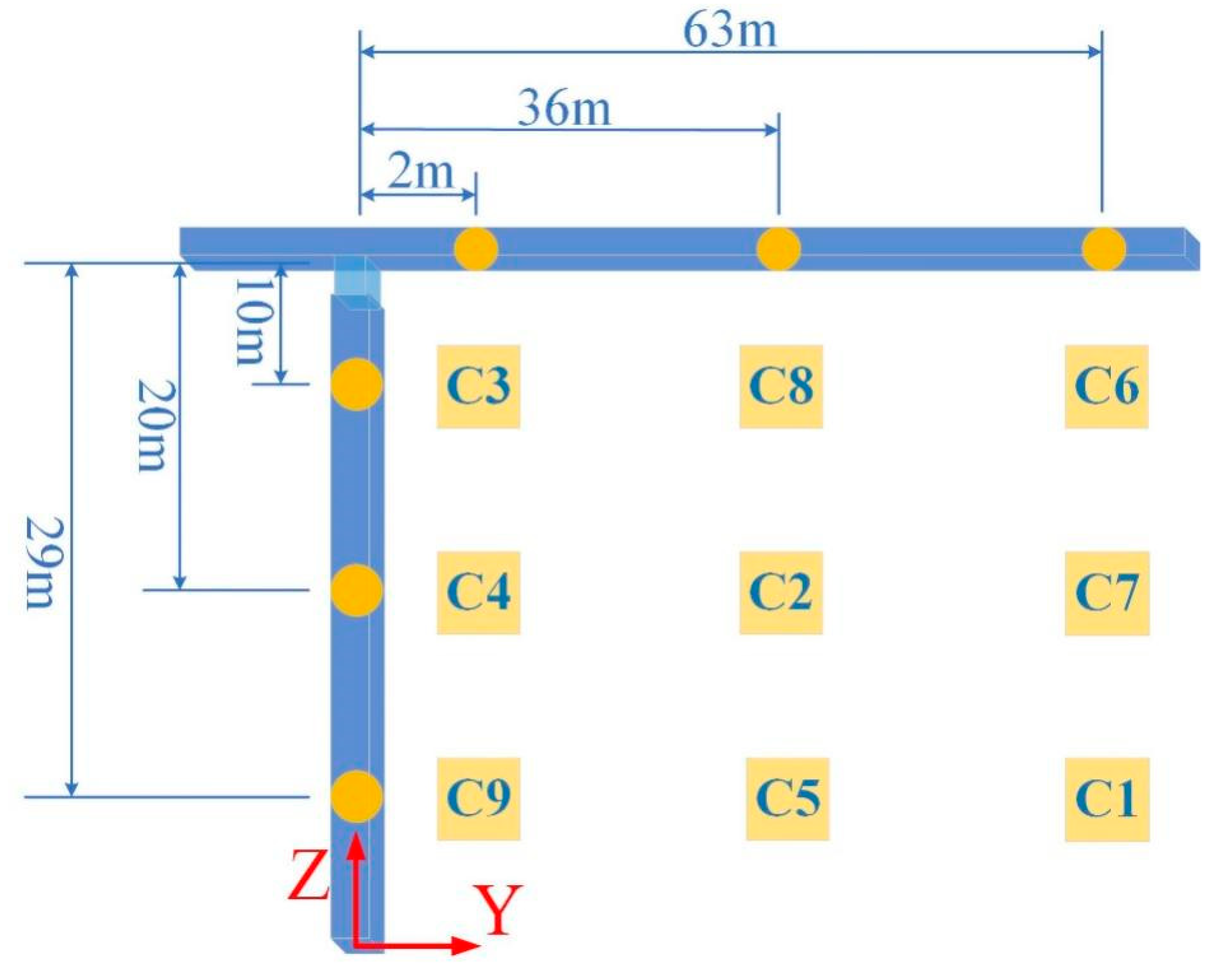
2.1. Project Overview and Test Arrangement

The object of the measurement is a flat-top tower crane in operation during the development of the Central Plains Digital Industrial Park (West Park) project. The project is located in the industrial park area of Zhongmu County, Zhengzhou City, between the southern auxiliary road of Jinshui Avenue and the northern side of Fugui Third Road. A tower crane located at the edge of the site, which is convenient for measurement operations, was selected as the test object for this experiment. The tower crane being tested is shown in Figure 1, and Table 1 presents the main performance parameters of the crane.
Due to the complex structure of the tower crane and the harsh working environment, there are many factors affecting its structural stress. In order to systematically study the stress distribution law of tower cranes, three key structural parameters of lifting position (A), rope length (B), and lifting weight (C) are selected as the analysis objects. Among these factors, the lifting position has a significant impact on the bending moment distribution and stress concentration of the tower crane. Different lifting positions alter the structural force distribution, thereby affecting the overall stability and safety of the tower crane. The rope length is a key factor in determining the dynamic response and stress distribution of the tower crane. Particularly during the lifting process, it directly influences the load swing characteristics and system stability, thereby altering the stress state of the tower crane. As the primary external load of the tower crane structure, lifting weight is a key factor influencing stress distribution. Different load levels can cause significant variations in internal forces, thereby profoundly affecting the safety and durability of the tower crane.
Each factor is set at three levels to comprehensively cover typical operating conditions in real-world engineering. The lifting position is set at 63 m (far from the tower), 36 m (mid-range), and 2 m (near the tower), representing the tower crane’s maximum, medium, and minimum working radii. These positions reflect the structural response under extreme, typical, and light load conditions. The rope length is set at 29 m, 20 m, and 10 m, representing the tower crane’s maximum, medium, and short rope lengths, respectively. This setup is used to study the effects of different swing amplitudes and dynamic responses on structural stresses. The lifting weights are set at 520 kg, 750 kg, and 1300 kg, representing light, medium, and near-rated load conditions, respectively, to analyze the structural response under different stress states. Table 2 lists the specific impact factors and their levels. The selection of these parameters is based on the typical working conditions of the tower crane in actual construction. It covers a range of scenarios, from light to heavy loads, short to long lifting ropes, and positions close to or far from the tower body. This ensures that the test results comprehensively reflect the structural response characteristics of the tower crane under different conditions, providing a reliable basis for its optimal design and safety evaluation.
An orthogonal experimental method [27] was employed for the on-site measurements. Following the principle of orthogonality, nine representative working conditions were selected from all possible combinations using the L9(34) orthogonal table. Here, ‘9’ represents the number of trials, ‘3’ denotes the three levels for each factor, and ‘4’ signifies the maximum number of factors that can be examined. This design minimizes factor interactions, enabling a clear analysis of each factor’s individual effect on the structural response. By using the orthogonal table, the number of test conditions was reduced from 27 to 9, allowing for a comprehensive investigation of the influence of various factors and their interactions on tower crane structural stress with significantly improved test efficiency. The details of each condition are shown in Table 3. The specific position diagram of the working conditions is shown in Figure 2. The orthogonal experimental method achieved an efficient, rapid, and cost-effective experimental design. This approach ensures a balanced combination of all test factors while significantly reducing the number of tests, yielding the most representative experimental results.

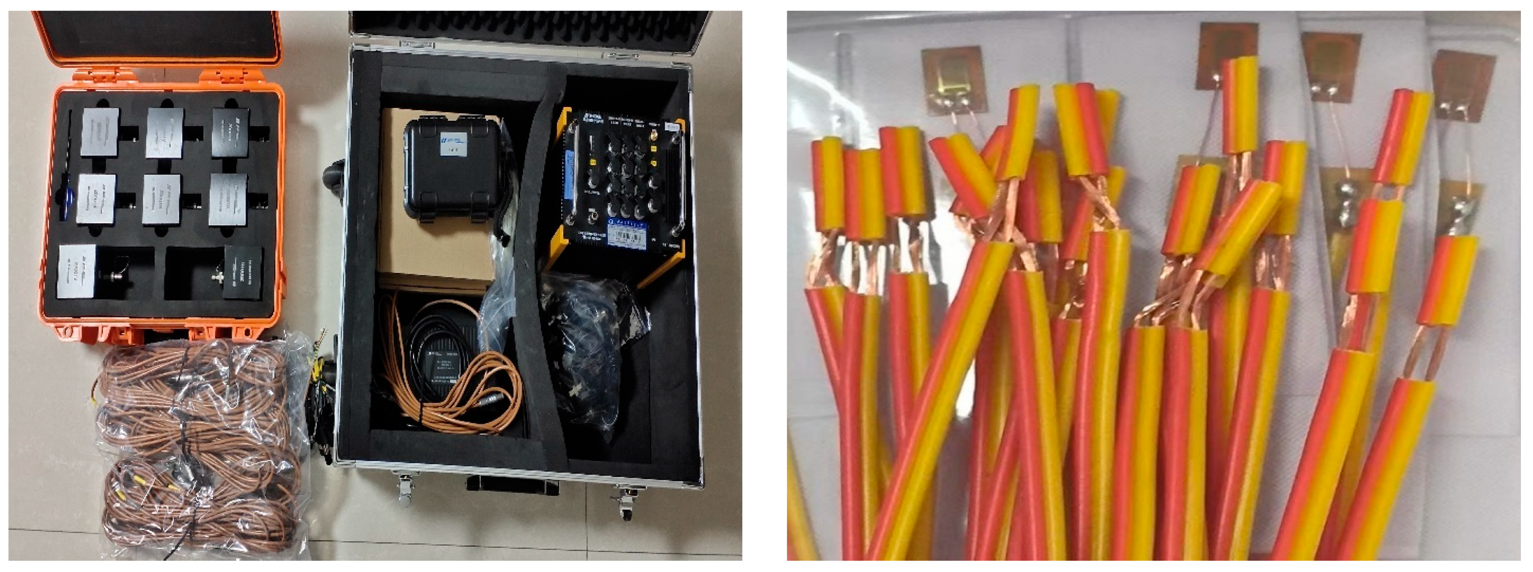
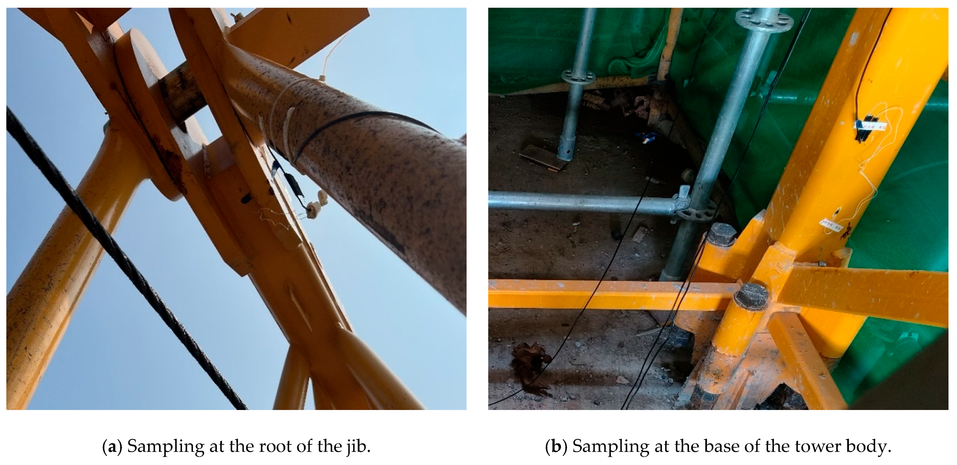
2.2. Testing Instruments and Measurement Point Arrangements

This study employed a passive monitoring method, where strain measurements of the tower crane under actual working conditions were recorded using the DH5902N (Donghua Testing Technology Co., Ltd., Taizhou, China) data acquisition and analysis system. No external excitations, such as impact hammers or vibrators, were applied. This method effectively captures the stress response under various working conditions and provides reliable data support for evaluating the performance of tower crane structures. The field test instrument mainly includes strain gauges, dynamic signal test and analysis systems, etc., and the signal acquisition instrument is the DH5902N rugged data acquisition and analysis system (see Figure 3). This device supports intelligent wire recognition and can connect to various sensors, enabling the testing and analysis of multiple physical parameters. It is capable of real-time data collection, transmission, storage, display, and analysis in harsh environments with strong vibrations and extreme temperatures, allowing it to perform long-term monitoring tasks. The resistance strain gauge adopts a foil-type uniaxial strain gauge, which has the characteristics of good flexibility, easy pasting, and stable performance. Its substrate material type is phenolic-acetal, and the substrate size is 10.1 mm × 4.0 mm in length × width. The dimensions of the sensitive grid are 5.0 mm × 2.0 mm in length × width. The lead material is PVC lead; the exposed diameter of the inner core is 0.09 mm, and the outer diameter of the lead is 0.9 mm. The resistance value of the strain gauge is 119.8 ± 0.1 Ω, the sensitivity coefficient is 2.20 ± 1%, and the operating temperature range is −30~80 °C.
Based on the actual on-site conditions, considering the structural characteristics of the flat-top tower crane and the experiment’s operational difficulties, the root of the tower body and the root of the jib were selected as the stress measurement locations. The specific arrangement of the measurement points is as follows: (1) Four strain gauges were attached around the cross-section at the root of the tower body, with the measurement points numbered A-1 to A-4. (2) One strain gauge was attached along the axial direction of the primary material at the root of the jib, with the measurement point numbered B-1. Figure 4 shows the schematic diagram of the measurement point layout for the on-site tower crane. During the on-site testing, the X-axis was set perpendicular to the jib direction, the Y-axis was aligned along the jib direction, and the Z-axis was oriented vertically. The experiment’s field sampling is shown in Figure 5.
During the on-site measurements, the weather conditions were clear, with temperatures ranging from 26 °C to 35 °C and an average of approximately 30 °C. The wind, predominantly from the southeast at level 2, persisted throughout the day and night, with a relative humidity of 66%. Wind speed data were recorded in real-time using the anemometer mounted on the control panel inside the operator’s cabin. Under various working conditions, the measured wind speed at the top of the tower crane ranged from a minimum of 0.3 m/s to a maximum of 2.4 m/s.

3. Results

During the on-site testing, strain gauges were attached at the root of the tower body and the root of the jib. The sampling frequency for the measurement points was set to 50 Hz, and typical working conditions were selected for preliminary testing and analysis. Several short segments of signals were collected, and it was observed that all channels could effectively capture the measured signals. The selected range was appropriate, and the data were complete and reliable. During the formal testing, when the tower crane was in different working states, data collection of strain signals at each measurement point began when the crane reached the predetermined position and was stable.
During field sampling, to ensure data adequacy and representativeness, each sampling session was set to 600 s (10 min). Strain signals at various measurement points were recorded under different working conditions according to the on-site measurement layout. In total, 45 sets of strain data were collected during the field test. Figure 6 presents the strain history at A-1 and A-2, located at the root of the tower, under working condition C2. Due to the impact of the construction environment, the measured strain signals contained noise and irrelevant signals. Therefore, low-pass filtering was applied to the measured signals in MATLAB R2021b (Version 9.11) to improve the data’s signal-to-noise ratio.

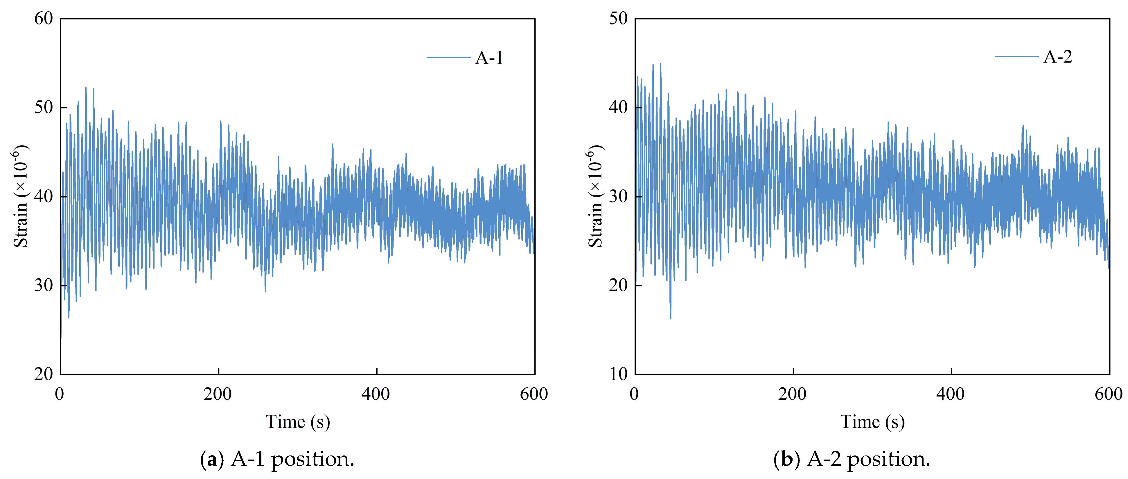
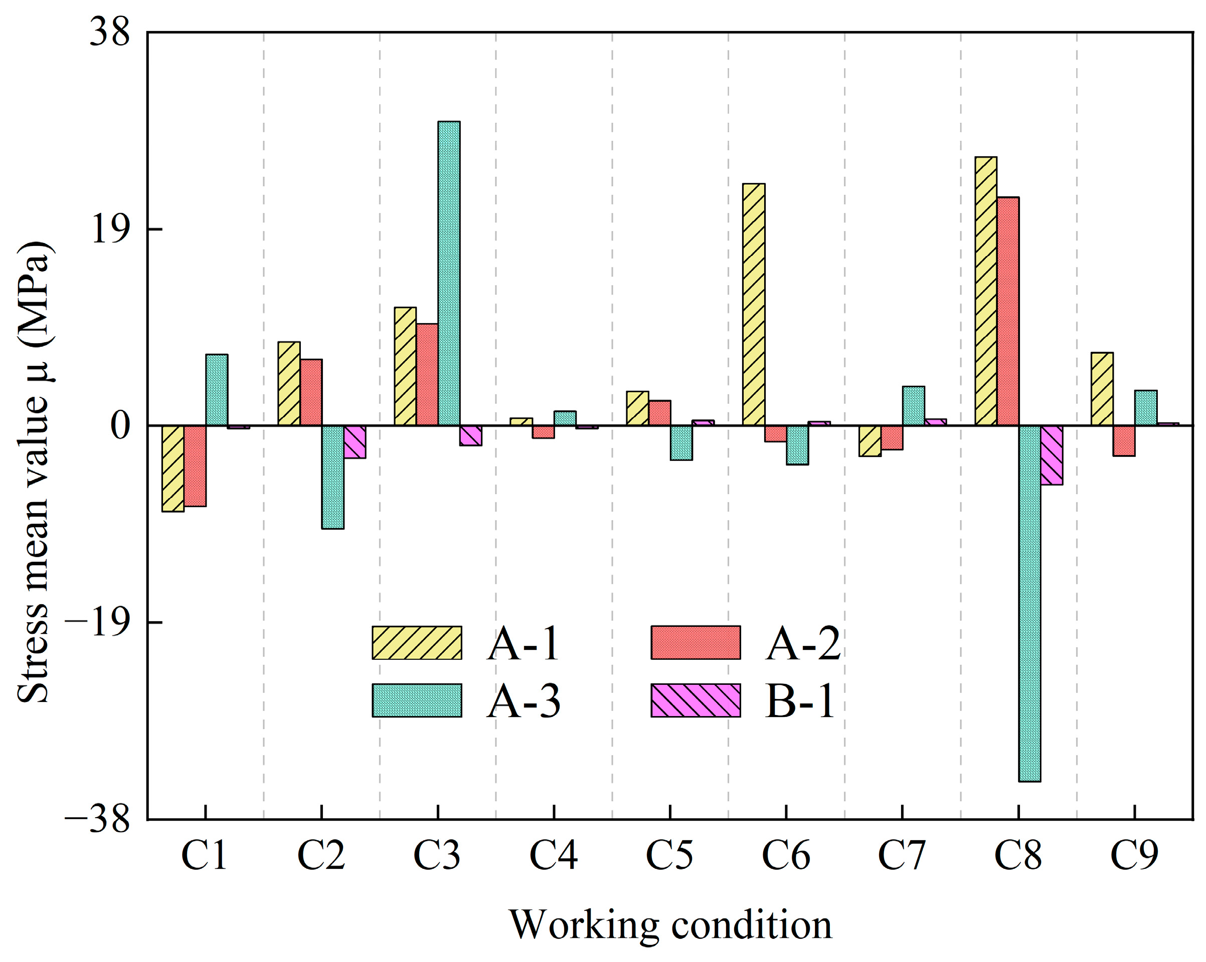
3.1. Stress Measurement Results

During the on-site measurements, strain gauges were attached when the tower crane was unloaded (with no lifting load). The measured stress represents the additional stress relative to the initial balanced state of the tower crane. While the tower crane was in operation, all parts underwent elastic deformation. Based on Hooke’s Law, the filtered strain time history was converted into a stress time-history, resulting in the stress values at each measurement point under different working conditions. Due to the large number of measurement points, only the stress identification results for a subset of the measurement points are provided in the paper. Table 4 presents the measured results of the stress mean (µ) and stress standard deviation (σ) for selected measurement points at the root of the tower body and the root of the jib.
Figure 7 shows the stress mean values at the measurement points under different working conditions. The maximum stress mean value under different working conditions occurs at various measurement points. Under C3 and C6, the stress values at the root of the tower body are significantly different, while the stress values under other working conditions show only minor differences. The stress mean values at the measurement points at the root of the tower body (A-1 to A-3) are all greater than the stress mean value at the measurement point at the root of the jib (B-1). The stress at the root of the jib is mainly caused by bending moments, while the stress at the root of the tower body is due to both bending moments and the additional stress caused by gravity. Under working condition C8, the maximum stress values at both the root of the tower body and the root of the jib occur. This is likely because, in condition C8, the lifting weight is the largest, and the rope length is the shortest. A longer rope can dampen the tower crane, reducing vibrations and stress. The nine working conditions were divided into three groups for comparison, each with consistent lifting weight. The working conditions with the shortest rope length in each group were C3, C6, and C8. The stress values under these conditions were higher than those in the other conditions within their respective groups.

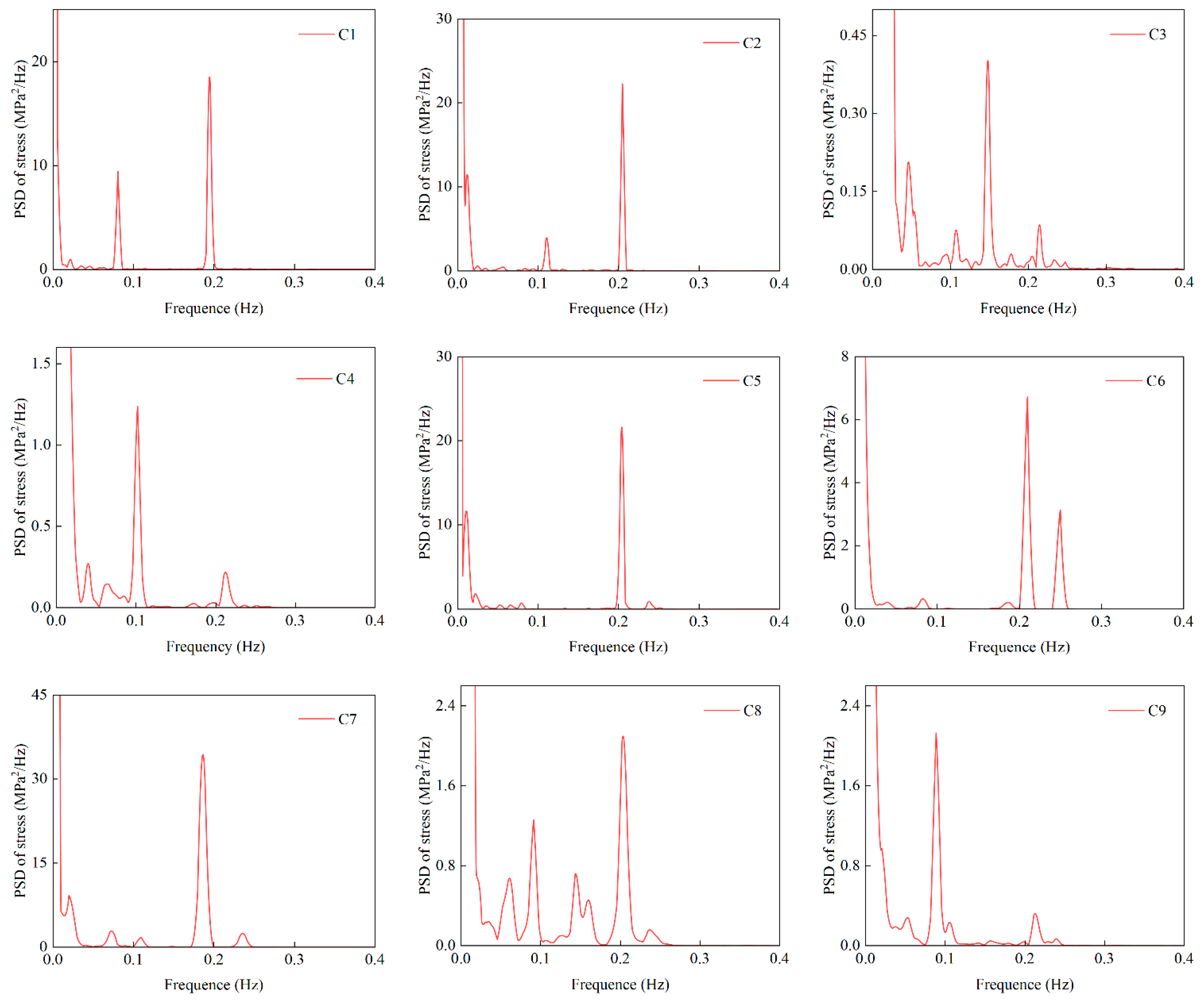
3.2. Stress Response Spectrum

By conducting a power spectral density (PSD) analysis on the measured stress time-history signal, its frequency domain representation is obtained. The natural frequencies are identified from the prominent peaks in the PSD curve, which correspond to the primary vibration frequencies of the structure. Figure 8 shows the stress–power spectral density curves of the A-1 position under different working conditions, and the following conclusions can be drawn by combining the identification results of the first two natural frequencies of the tower crane in Table 5: Under working condition C5, the first-order frequency characteristics of the structure are not pronounced, but a significant peak is observed at 0.204 Hz. Under working conditions, C3, the first-order and second-order frequencies of the structure are 0.108 Hz and 0.148 Hz, respectively. In most cases (C1, C2, C4, C6, C7, C8, C9), the first- and second-order frequencies of the structure are stable at about 0.10 Hz and 0.20 Hz, respectively.
By comparing and analyzing the natural frequency results of tower cranes based on dynamic response recognition in the literature 28 (see Table 5), it is found that there is a large deviation in the first-order frequency recognition results under working conditions C1 and C2, but the error of the second-order frequency recognition results is controlled within 0.5%. Under other working conditions, the error of the natural frequency recognition result does not exceed 5%. (error calculation formula: error = (recognition result of this paper − recognition result of the literature 28)/recognition result of the literature 28 × 100%).
In summary, the natural frequency recognition results based on velocity response in [28] are in good agreement with the research in this paper. It is further confirmed that under suitable working conditions, the natural frequency of the tower crane can be accurately identified through the power spectral density analysis of the stress response of the tower crane root. This discovery provides a new technical approach for the field test of the structural dynamic characteristics of tower cranes and has important engineering application value for the safety assessment and health monitoring of tower cranes.

3.3. Orthogonal Experimental Analysis of Stress

The orthogonal test method is an efficient and scientific multi-factor test design method that can comprehensively analyze the influence of various factors and their interactions in a small number of experiments through the rational arrangement of the orthogonal table. Its core advantages lie in efficiency, comprehensiveness, and scientificity. This method is widely used in engineering optimization and other fields [29,30,31] and is a powerful tool to solve multi-factor optimization problems. The orthogonal test method has significant advantages in identifying key parameters and optimizing structural design. However, it is based on the assumption that interactions between factors are negligible, which may not hold true under complex or wide-ranging load conditions. Orthogonal test methods struggle to effectively capture such complex behaviors. Therefore, caution should be exercised when applying orthogonal test methods in scenarios involving highly nonlinear loading conditions.
Considering the numerous measurement points on the tower crane, this paper selects the measurement points at the root of the tower (A-1, A-2) and the upper chord of the jib root (B-1) as representatives. The study focuses on the effects of lifting position (A), rope length (B), and lifting weight (C) on the structural stress of the tower crane. The measured stress mean values were used as the analysis indicators for the orthogonal experiment. By conducting range analysis and variance analysis on the experimental results, each factor’s influence on the tower crane’s structural stress and the significance level of each factor were determined, providing a reference for the following research phase.

3.3.1. Range Analysis

Table 6 shows the arrangement of the orthogonal experiment. Table 7 presents the results of the range analysis for the orthogonal experiment, where Ki (i = 1, 2, 3) represents the sum of the experimental results for the level of a given factor, with the mean value indicated, representing the range, reflecting each factor’s influence on the response variable. Based on the range R, the influencing factors can be ranked. A larger R indicates that the variation of that factor has a more significant impact on the response variable, making the factor more critical [32]. In the analysis, only the main effects on the structural stress mean values were considered, while the interaction effects between the factors were ignored. As shown in Table 6, by comparing the corresponding mean values and ranges of each experimental factor, the influence of each factor on the structural stress can be determined. At point A-1, with RB > RA > RC, the primary order of impact on the stress mean values is as follows: rope length > lifting position > lifting weight. This indicates that rope length is the most crucial factor affecting the stress mean values. At points A-2 and B-1, with RA > RB > RC, the order of importance for the factors affecting the stress mean values is as follows: lifting position > rope length > lifting weight. This indicates that lifting position is the most critical factor influencing the stress mean values. Lifting weight has the least influence on the stress mean values at both the root of the tower body and the root of the jib.

3.3.2. Variance Analysis

Range analysis does not distinguish between experimental error effects and factor effects; it only reflects the relative importance of the factors influencing the experimental response. In contrast, variance analysis decomposes the sum of squares of deviations in the experimental data into the sum of squares for each factor’s deviation and the sum of squares for experimental errors. By comparing the sum of squares of deviations for each factor with the sum of squares for experimental errors, the extent of each factor’s influence on the response variable can be explained, and the significance of each factor’s effect can be verified.
The results of the variance analysis for the factors affecting the structural stress of the tower crane are shown in Table 8. The F-value is used to measure the significance of the influence of the factor level change on the experimental index, and the larger the F-value, the more significant the influence of the factor on the experimental index. According to the F distribution table, F0.10(2,2) = 9.00 and F0.05(2,2) = 19.00. At A-1, FC < FA < FB < F0.05(2,2) = 19.00, and the influence of each factor on the structural stress is as follows: rope length > lifting position > lifting weight. At A-2 and B-1, FC < FB < FA < F0.05(2,2) = 19.00, and the influence of each factor on the structural stress is as follows: lifting position > length of lifting rope > lifting weight. This is consistent with the conclusion of the range analysis, which further verifies the reliability of the analysis. In addition, the influence of the lifting position, rope length, and lifting weight on the stress of the tower crane did not reach a significant level (p > 0.05), and there was no statistically significant difference.
Analyze the proportion of the F-value of each measurement point: for the measurement point at the root of the tower, at A-1, the F-value of the length of the lifting rope accounts for the largest proportion, reaching 79.7%, indicating that it has the most significant influence on the structural stress. At A-2, the influence of the lifting position predominates, with an F-number of 49.4%. Lifting weight has the least effect on the root stress of the tower, and the F-value accounts for only 7.8%. For the measuring point B-1 at the root of the boom, the F-value of the lifting position accounted for the largest proportion, which was 46.0%; The impact of lifting weight was the smallest, and the F-number accounted for 22.7%.
In summary, the length of the lifting rope and the lifting position are the main factors affecting the structural stress of the flat arm tower crane, while the influence of the lifting weight is relatively weak. The results of this analysis provide an important theoretical basis for the optimization of structural lightweight and the selection of working conditions.

4. Conclusions

In this paper, a 40 m-high flat-arm tower crane is taken as the research object, and the real-time working stress of the crane under various typical working conditions is obtained through on-site stress measurements. Compared with theoretical analysis methods and numerical simulations, on-site measurements can directly reflect the mechanical characteristics of tower cranes in real operating environments. This approach avoids errors caused by model simplifications and parametric assumptions. Through actual measurements, we have clarified the stress state of key components of the flat-arm tower crane and accurately identified its natural frequencies. The effects of lifting position, rope length, and lifting weight on structural stress were systematically analyzed. The research results provide a reliable reference and basis for the health monitoring and safety assessment of tower crane structures. They have practical engineering value for ensuring the safety and durability of tower crane operations. The main conclusions of this study are as follows:
(1) Through real-time working stress tests, the stress distribution characteristics of key components of the flat-arm tower crane have been determined. It was found that the average stress at each measuring point at the root of the tower body is generally higher than that at the root of the boom. Notably, the maximum stress value under different working conditions is not fixed at a specific measurement point but varies with the working conditions.
(2) The natural frequency of a structure is independent of the applied load. Based on the power spectral density analysis method, the natural frequency of the tower crane structure was successfully identified. The results show that the first-order natural frequency of the tower crane structure is approximately 0.10 Hz, while the second-order natural frequency is around 0.20 Hz under different working conditions. By analyzing the power spectral density curve of the stress response at the root of the tower crane, the natural frequency of the structure can be accurately determined. This not only verifies the feasibility of identifying the natural frequency of the structure through stress monitoring but also provides a reliable technical approach for the dynamic characteristics analysis and health monitoring of flat-arm tower cranes, offering significant engineering application value.
(3) Using the orthogonal test method, the influence of three key structural parameters—lifting position, rope length, and lifting weight—on the structural stress of the tower crane was systematically studied. The results indicate that the effects of these three factors on the structural stress of the tower crane are consistent, with no significant differences (p > 0.05). Through the analysis of F-value weights, it was found that the lifting position and the length of the lifting rope are the primary factors affecting the stress at the root of the tower crane and the root of the boom, while the influence of the lifting weight is relatively small. This conclusion provides an important basis for the optimization and safety assessment of tower cranes. In practical applications, it is essential to comprehensively consider the coupling effects of multiple parameters to achieve the efficient and safe operation of the tower crane structure.
This study was conducted on a specific tower crane. Due to differences in material properties, geometric configuration, boundary conditions, and working environments, the research findings are primarily applicable to the analyzed tower crane structure. However, the methods and findings presented in this paper provide a valuable reference for understanding the stress distribution and fatigue behavior of this type of tower crane. Caution should be exercised when generalizing these conclusions to tower cranes with different designs or operating conditions. For other types of tower cranes, further research is required to account for variations in structural characteristics, load scenarios, and environmental factors.
This study establishes a robust experimental foundation for the optimal design and safety evaluation of tower cranes. Future research should be extended to a broader range of tower crane types, systematically investigating their stability, modal characteristics, and dynamic response under complex working conditions through an integrated approach combining on-site measurements, theoretical analysis, and numerical simulation. By leveraging a multi-method collaborative analysis, the mechanical behavior of tower cranes can be assessed with greater accuracy, enabling the development of a more generalized theoretical framework and providing a solid foundation for engineering applications. Furthermore, future studies should emphasize the long-term structural health monitoring of tower cranes, systematically evaluating their fatigue performance and damage evolution. This would offer scientific guidance for ensuring their safe operation and extending their service life while enhancing their stability and reliability under complex environmental conditions.

Author Contributions

Conceptualization, H.Y., X.H. and W.A.; methodology, Q.Z. and Z.W.; investigation, Y.Y., Q.Z. and Y.X.; writing—original draft preparation, B.M., Q.Z. and H.Y.; writing—review and editing, B.M. and Q.Z. All authors have read and agreed to the published version of the manuscript.

Funding

Henan Province Science and Technology Research and Development Program Joint Fund (Applied Research Category) Project (242103810102); The Key Research Programs of Higher Education Institutions in Henan Province (24B560012); The Henan Province Science and Technology Research Projects (242102320046); China State Construction Engineering Corporation Scientific Research Project (CSCEC-2021-Q-63).

Data Availability Statement

The data presented in this study are available on request from the corresponding author.

Conflicts of Interest

Hui Yang was employed by the China Construction Third Engineering Bureau Group Co., Ltd. Wei An was employed by the POWER CHINA Henan Electric Power Engineering Co., Ltd. The remaining authors declare that the research was conducted in the absence of any commercial or financial relationships that could be construed as a potential conflict of interest.

References

  1. Sadeghi, S.; Soltanmohammadlou, N.; Rahnamayiezekavat, P. A systematic review of scholarly works addressing crane safety requirements. Saf. Sci. 2021, 133, 105002. [Google Scholar] [CrossRef]
  2. Jeong, I.; Hwang, J.; Kim, J.; Chi, S.; Hwang, B.; Kim, J. Vision-based productivity monitoring of tower crane operations during curtain wall installation using a database-free approach. J. Comput. Civ. Eng. 2023, 37, 04023015. [Google Scholar] [CrossRef]
  3. Hu, S.; Fang, Y.; Moehler, R. Estimating and visualizing the exposure to tower crane operation hazards on construction sites. Saf. Sci. 2023, 160, 106044. [Google Scholar] [CrossRef]
  4. Jiang, W.; Ding, L. Unsafe hoisting behavior recognition for tower crane based on transfer learning. Autom. Constr. 2024, 160, 105299. [Google Scholar] [CrossRef]
  5. Chen, Y.; Zeng, Q.; Zheng, X.; Shao, B.; Jin, L. Safety supervision of tower crane operation on construction sites: An evolutionary game analysis. Saf. Sci. 2022, 152, 105578. [Google Scholar] [CrossRef]
  6. Ali, A.; Zayed, T.; Wang, R.; Kit, M. Tower crane safety technologies: A synthesis of academic research and industry insights. Autom. Constr. 2024, 163, 105429. [Google Scholar] [CrossRef]
  7. Zhang, J.; Huang, M.; Wan, N.; Deng, Z.; He, Z.; Luo, J. Missing measurement data recovery methods in structural health monitoring: The state, challenges and case study. Measurement 2024, 231, 114528. [Google Scholar] [CrossRef]
  8. Deng, Z.; Huang, M.; Wan, N.; Zhang, J. The current development of structural health monitoring for bridges: A review. Buildings 2023, 13, 1360. [Google Scholar] [CrossRef]
  9. Jiang, H.; Jiang, X. Fatigue life prediction for tower cranes under moving load. J. Mech. Sci. Technol. 2023, 37, 6461–6466. [Google Scholar] [CrossRef]
  10. Yang, M.; Chang, Z.; Xu, G.; Wang, C.; Wang, P. Analysis on fatigue life of overhead travelling crane girder under impact load for sustainable transport system. IET Intell. Transp. Syst. 2020, 14, 1426–1432. [Google Scholar] [CrossRef]
  11. Lehner, P.; Krejsa, M.; Parenica, P.; Krivy, V.; Brozovsky, J. Fatigue damage analysis of a riveted steel overhead crane support truss. Int. J. Fatigue 2019, 128, 105190. [Google Scholar] [CrossRef]
  12. Li, Y.; Jin, A.; Dai, Y.; Yang, D.; Zheng, B.; Correia, J. Prediction of remaining fatigue life of in-service bridge cranes. Appl. Sci. 2023, 13, 12250. [Google Scholar] [CrossRef]
  13. Dong, Q.; Yu, Y.; Xu, G. Fatigue residual life estimation of jib structure based on improved v-SVR algorithm obtaining equivalent load spectrum. Fatigue Fract. Eng. Mater. Struct. 2020, 43, 1083–1099. [Google Scholar] [CrossRef]
  14. Jeongwoo, H.; Geun-Ho, L. Fatigue life prediction of the carrier of slewing reducer for tower crane. J. Korean Soc. Manuf. Process Eng. 2015, 14, 131–140. [Google Scholar] [CrossRef]
  15. Hectors, K.; Chaudhuri, S.; De Waele, W. Fracture mechanics and hot spot stress-based fatigue life calculation: Case study for a crane runway girder. Fatigue Fract. Eng. Mater. Struct. 2022, 45, 2662–2675. [Google Scholar] [CrossRef]
  16. Moskvichev, V.; Chaban, E. Analysis of propagation of fatigue cracks in crane girders. Inorg. Mater. 2019, 55, 1496–1502. [Google Scholar] [CrossRef]
  17. He, Z.; Gao, M.; Liang, T.; Lu, Y.; Lai, X.; Pan, F. Tornado-affected safety assessment of tower cranes outer-attached to super high-rise buildings in construction. J. Build. Eng. 2022, 51, 104320. [Google Scholar] [CrossRef]
  18. Lu, Y.; Gao, M.; Liang, T.; He, Z.; Feng, F.; Pan, F. Wind-induced vibration assessment of tower cranes attached to high-rise buildings under construction. Autom. Constr. 2022, 135, 104132. [Google Scholar] [CrossRef]
  19. Chen, W.; Qin, X.; Yang, Z.; Zhang, P. Wind-induced tower crane vibration and safety evaluation. J. Low Freq. Noise Vib. Act. Control. 2020, 39, 297–312. [Google Scholar] [CrossRef]
  20. Pástor, M.; Lengvarsky, P.; Hagara, M.; Kulka, J. Experimental investigation of the fatigue life of a bridge crane girder using S-N method. Appl. Sci. 2022, 12, 10319. [Google Scholar] [CrossRef]
  21. Xi, Y.; Li, H.; Sun, L.; Wang, Z. Extreme load extrapolation and long-term fatigue assessment of offshore wind turbine tower based on monitoring data. Ocean Eng. 2024, 300, 117180. [Google Scholar] [CrossRef]
  22. Park, Y.; Cho, S.; Han, J.; Shim, S. Fatigue life prediction of planet carrier in slewing reducer for tower crane based on model validation and field test. Int. J. Precis. Eng. Manuf. 2017, 18, 435–444. [Google Scholar] [CrossRef]
  23. Liu, F.; Yang, J.; Wang, J.; Liu, P. Tower Crane Effect on the Vibration Response of Elastic Foundation. Iran. J. Sci. Technol. Trans. Civ. Eng. 2023, 47, 3839–3850. [Google Scholar] [CrossRef]
  24. Xu, B.; Wu, Q. Stress fatigue crack propagation analysis of crane structure based on acoustic emission. Eng. Fail. Anal. 2020, 109, 104206. [Google Scholar] [CrossRef]
  25. Li, Q.; Fan, W.; Huang, M.; Jin, H.; Zhang, H.; Ma, J. Machine learning-based prediction of dynamic responses of a tower crane under strong coastal winds. J. Mar. Sci. Eng. 2023, 11, 803. [Google Scholar] [CrossRef]
  26. Wei, G.Q.; Yin, Q.Z.; Zhao, Y.; Dang, Z.; Lu, Z.W. Fatigue failure analysis and life prediction of wheel load local area of ladle crane. Meas. Sci. Technol. 2024, 35, 126120. [Google Scholar] [CrossRef]
  27. Dai, S.; Wang, H.; An, S.; Yuan, L. Mechanical properties and microstructural characterization of metakaolin geopolymers based on orthogonal tests. Materials 2022, 15, 2957. [Google Scholar] [CrossRef]
  28. Zhang, Q.; Wang, Z.; Yang, H.; Zhao, J.; Xu, Y. Field Test and Analysis of Influence Factors on the Dynamic Characteristics of Self-Supporting Flat Arm Tower Crane Under Multiple Working Conditions. J. Vib. Eng. 2024, 1–9. Available online: http://kns.cnki.net/kcms/detail/32.1349.TB.20240829.1811.006.html (accessed on 20 February 2025). (In Chinese).
  29. Chen, M.; Zhang, Z.; Deng, Q.; Feng, Y.; Wang, X. Optimization of underfloor air distribution systems for data centers based on orthogonal test method: A case study. Build. Environ. 2023, 232, 110071. [Google Scholar] [CrossRef]
  30. Li, Y.; She, L.; Wen, L.; Zhang, Q. Sensitivity analysis of drilling parameters in rock rotary drilling process based on orthogonal test method. Eng. Geol. 2020, 270, 105576. [Google Scholar] [CrossRef]
  31. Li, X.; Hao, J. Orthogonal test design for optimization of synthesis of super early strength anchoring material. Constr. Build. Mater. 2018, 181, 42–48. [Google Scholar] [CrossRef]
  32. Xu, L.; Zhang, Y.; Zhang, Z.; Taylor, S.; Chen, M.; Wang, X. Experimental investigation on thermal performance of self-service cold storage cabinet based on the orthogonal test. Appl. Therm. Eng. 2024, 242, 122315. [Google Scholar] [CrossRef]
Figure 1. The tower crane of the test site.
Buildings 15 01137 g001
Figure 2. The specific position diagram of the working conditions.
Buildings 15 01137 g002
Figure 3. Field test instrument.
Buildings 15 01137 g003
Figure 4. Layout of the measurement point at the site.
Buildings 15 01137 g004
Figure 5. Diagram of sampling at the experimental site.
Buildings 15 01137 g005
Figure 6. Strains at A-1 and A-2 under case C2.
Buildings 15 01137 g006
Figure 7. The mean stress μ at each measurement point under different working conditions.
Buildings 15 01137 g007
Figure 8. PSD of stress response at A-1 under different working conditions.
Buildings 15 01137 g008
Table 1. Main performance parameters of tower crane.
ParameterValueParameterValue
Operating range (m)2.5~65Independent working height (m)46
Maximum lifting weight (kg)1.00 × 10⁴Measured tower crane height (m)40
Balance weight (kg)1.86 × 10⁴Rated lifting moment (kN·m)1600
Lift arm length (m)66.8Maximum lifting moment (kN·m)1920
Balance arm length (m)15.5Lifting speed (m·min−1)0~95
Table 2. The factors and levels based on orthogonal design.
LevelFactors
Lifting Position (m)Rope Length (m)Lifting Weight (kg)
16329520
23620750
32101300
Table 3. Measured working conditions table.
No.Lifting Position (m)Rope Length (m)Lifting Weight (kg)
C16329520
C23620520
C3210520
C4220750
C53629750
C66310750
C763201300
C836101300
C92291300
Table 4. Stress identification results of measuring points under different working conditions.
No.The Root of the Tower Body
(MPa)
The Root of the Jib
(MPa)
A-1A-2A-3B-1
µσµσµσµσ
C1−8.2840.714−7.8070.7136.8850.784−0.2600.367
C28.1060.6586.4270.614−9.9350.781−3.1230.331
C311.4460.7519.8980.67729.38511.804−1.9010.225
C40.7220.414−1.1830.4911.4270.510−0.2690.589
C53.3470.5872.4590.639−3.3030.7440.4920.638
C623.3841.465−1.5370.602−3.7330.7540.3870.366
C7−2.9091.298−2.2831.2053.8211.6560.6350.589
C825.9881.56622.0651.358−34.3352.083−5.6560.455
C97.0770.614−2.9070.7343.4270.6370.2550.664
Table 5. Comparison of natural frequency identification results of tower cranes under different working conditions.
No.Natural Frequency Results in This Document/HzNatural Frequency Results/Hz [28]Error/%
First OrderSecond OrderFirst OrderSecond OrderFirst OrderSecond Order
C10.0810.1940.1140.195−28.95−0.51
C20.1100.2050.1240.205−11.290
C30.1080.1480.1070.1470.930.68
C40.1020.2140.1070.206−4.673.88
C5/0.2040.1100.204/0
C60.0830.2100.0850.209−2.350.48
C70.0730.1870.0730.18600.54
C80.0910.2020.0910.2050−1.46
C90.0890.2130.0880.2121.140.47
Table 6. Orthogonal test analysis table.
No.Lifting Position
A
Rope Length
B
Lifting Weight
C
Mean Value of Stress (MPa)
A-1A-2B-1
C1111−8.284−7.807−0.260
C22218.1066.427−3.123
C333111.4469.898−1.901
C43220.722−1.183−0.269
C52123.3472.4590.492
C613223.384−1.5370.387
C7123−2.909−2.2830.635
C823325.98822.065−5.656
C93137.077−2.9070.255
Table 7. Range analysis table.
PositionParameterLifting Position ARope Length
B
Lifting Weight
C
Order of Importance
A-1K14.060.713.76
K212.481.979.15
K36.4120.2710.05
R8.4219.566.30B > A > C
A-2K1−3.88−2.752.84
K210.320.99−0.09
K31.9410.145.63
R14.1912.895.71A > B > C
B-1K10.250.16−1.76
K2−2.76−0.920.20
K3−0.64−2.39−1.59
R3.022.551.96A > B > C
Table 8. Results of Variance Analysis.
PositionSourceThe Sum of Squared DeviationsDegrees of FreedomFp
A-1A113.15720.8780.533
B719.03225.5770.152
C69.55720.5390.650
Error128.9382
R20.875
A-2A305.448213.9190.067
B264.038212.0320.077
C48.95022.2310.310
Error21.9452
R20.966
B-1A14.40622.8240.262
B9.84821.9300.341
C7.10121.3920.418
Error5.1012
R20.860
Disclaimer/Publisher’s Note: The statements, opinions and data contained in all publications are solely those of the individual author(s) and contributor(s) and not of MDPI and/or the editor(s). MDPI and/or the editor(s) disclaim responsibility for any injury to people or property resulting from any ideas, methods, instructions or products referred to in the content.

