Article

Understanding Structural Timber in Old Buildings in Lisbon, Portugal: From Knowledge of Construction Processes to Physical–Mechanical Properties

by
Dulce Franco Henriques
1,2
1
ISEL-Instituto Superior de Engenharia de Lisboa, Polytechnic Institute of Lisbon, Rua Conselheiro Emídio Navarro, 1, 1959-007 Lisboa, Portugal
2
CERIS, Instituto Superior Técnico, Universidade de Lisboa, Av. Rovisco Pais, 1049-001, Lisboa, Portugal
Buildings 2025, 15(7), 1161; https://doi.org/10.3390/buildings15071161
Submission received: 15 February 2025 / Revised: 24 March 2025 / Accepted: 24 March 2025 / Published: 2 April 2025

Abstract

:
This text provides a comprehensive overview of structural timber old buildings, from an in-depth analysis of construction processes to laboratory-based research aimed at establishing a pattern for estimating the density of wood in buildings. It is now widely recognised by society that historic buildings should be subject to conservation or rehabilitation. This article discusses the good technical knowledge that those involved in old buildings should have: the understanding of and respect for old construction techniques; rigorous inspections and diagnosis before a project; and the recognition of the properties of wooden structural elements, either visually or by means of non-destructive or semi-destructive testing methods (NDT/SDT). The final section of this article presents a laboratory study that correlates penetration resistance test results with wood density and verifies them in situ by direct analysis with wood core extraction. The aim of this study is to establish and verify a reliable pattern that allows the user to estimate the density of Scots pine in any structural member in service in an old building. The results obtained in the laboratory and of wood in service show that Equation (1) is a suitable pattern to obtain wood density through the wood penetration resistance test.

1. Introduction

This article is based on two fundamental premises: (i) the urgent reuse of part of the historic buildings in our city centres for public use as residential or service spaces and (ii) the necessary preservation of their constructive, architectural and decorative elements through scientific knowledge and the application of good practices [1,2,3].
To this end, it is essential that maintenance and rehabilitation activities are carried out in accordance with current knowledge and quality standards, respecting the original techniques and materials [4,5,6].
Bearing in mind that wood is a fundamental material in the structural systems of old buildings, due to its high resistance to bending, traction and compression, this article focuses on this noble material. It lays the foundations and draws attention to what is often talked about but very little practised: technicians must have the necessary knowledge to guarantee the quality of intervention processes in wooden structures [7]. The conservation or rehabilitation of existing wooden structures requires in-depth knowledge of the construction techniques used in each era [1,5,8]. It is also necessary to have an improved ability to recognise their state of conservation, to know how to classify each wooden element in service according to VSG rules and to be able to assess the material’s properties [7,9,10,11] in order to understand the construction system as a whole, respecting the function that each structural element (still) performs and the capacity with which it does so [12].
The construction technique that began to be implemented after the great Lisbon earthquake of 1755 highlighted the central role that wood played in the complex structural systems of the time. These braced frame timber buildings with masonry infill are known as the “Gaiola Pombalina” [13,14]. It also shows how these construction systems were successively simplified throughout the 19th century until they were no longer built in the first half of the 20th century, with the introduction of reinforced concrete in the construction industry [4,13,15].
Identifying the species, estimating the density, strength and stiffness of wooden building elements often poses challenges, leading to uncertainties that make it difficult to assess safety. In this sense, the scientific community has evolved significantly, systematically searching for and testing, in a laboratory and in situ, numerous methods of the inspection, diagnosis and structural assessment of existing timber structures, including the continuous monitoring of their actual performance [11,16,17,18,19,20,21].
It is stated in [22] that the identification of wood species and the consequent assignment of properties should always be considered as a starting point in the process of evaluating existing timber structures.
Density is arguably the most effective single criterion of resistance. It is utilised in the selection of trees within a stand, as well as in the classification of wood according to its intended applications, given its positive correlation with the wood’s mechanical properties (strength and stiffness) [20,21].
A non-destructive density assessment is typically conducted through the following methodologies: the application of visual strength classification standards (limited to coniferous trees); the extraction of wood samples via cores; and resistance drilling tests. In recent decades, various non-destructive testing (NDT) methods have been developed, with drilling resistance being one of the most widely used semi-destructive techniques [21] along with the penetration resistance method due to its ease of execution and applicability to timber in service.
A direct assessment of physical and mechanical properties can be achieved by some SDTs [16]. Indirect methods (NDT or SDT) are often applied in situ, based on empirical models such as regression analysis, which relate indirect measurements (by ultrasonic, imaging or penetration methods) to the properties of interest (e.g., static modulus, density) [20,23].
This article deals with a research study centred on recognising the density of wooden elements [24]. To this end, non/semi-destructive penetration resistance tests were carried out with Pilodyn-type equipment, which were correlated with density in a laboratory environment. At the same time, wooden elements in use in old buildings were tested using the same semi-destructive method, and the results were correlated with those obtained from reading the wood cores of the same elements. The final analysis includes all the data obtained by both methodologies and assesses their proximity [24,25,26].
Figure 1 shows a flowchart of the sequence of subjects covered in this article and their interrelationship.

2. Wood Construction Techniques from the 18th to the 20th Century

Traditionally, old buildings with masonry and timber structures combine the lightness, ductility and flexural strength of timber structural elements with the compressive strength of stone masonry [4,27].
Due to its structural and practical advantages, this construction system has been used in various seismic zones throughout history, for example, in Italy, Greece, Turkey, Albania, Romania and Portugal [13,14,28].
In Portugal, especially in the centre and south, the wood is not exposed to the outside environment. It is usually embedded inside irregular masonry walls with lime mortar, although sometimes, it is only embedded in mortar in secondary walls. It is also responsible for the structure of floors, stairs and roofs. Both the walls and the ceilings of the floors and staircases are generally clad in stucco or lime mortar-covered slabs, both of which are coated with stucco [29].

2.1. Masonry and Wood Constructions from the Pombal Period and the Like

The importance of wood as a building material reached its peak at that time with the rise in the frontal technique, which consists of building a wooden structure partially filled with masonry in walls. These walls are connected to the floor and roof structures, forming the ‘Pombalino’ cage [16,28]. In this way, a highly flexible three-dimensional reticulated structure is formed, which, combined with a high energy dissipation capacity, gives the buildings exceptional anti-seismic characteristics [4,18].
‘Pombalino’ construction stipulated the height of buildings at three storeys above the ground floor and added a mansard. It consisted of thick stone masonry walls connected to a three-dimensional interior wooden portico. The ground floor was usually made up of stone arches or brick vaults. Above this floor, a three-dimensional locking system was built, formed horizontally by the wooden structures of the floors and roof and vertically by the caged partition walls [18]. The caged walls, placed in orthogonal directions and equipped with additional locking elements along the connection to the floors, give the whole construction high ductility and structural strength [18,30]. At the time, great importance was attached to the rigour applied to the construction details of the cage’s connection to the masonry, essentially by means of metal studs set into the stones [15,30].
According to [4], chestnut, of national origin, and Scots pine, of extra-national origin, were the species most frequently utilised in timber structures. To a lesser extent, pitch pine was also used in important works, as well as poplar, cedar and oak.

2.2. Masonry and Timber Construction of the “Gaioleiro” Type

The great urban growth that took place in Lisbon in the second half of the 19th century, more specifically from the 1870s onwards, is characterised by the occupation of large areas and the increase in the height of one or two floors of many of the existing Pombaline buildings [1,15]. The new buildings are progressively taller, 5 to 6 storeys, and the three-dimensional wooden structure is used less and less, with some elements of the horizontal solidisation of the main walls being set aside [30].
The differences resulting from the abandonment of the frontal technique in the execution of the walls are noteworthy, with the generalised construction of master walls on the main and rear façades in thick stone masonry, solid brick walls around 30 cm thick in the gables and partition walls in partition walls or perforated brick [1,30]. At the same time, the structure of the wooden beamed floors began to discharge directly onto the walls, through a few centimetres of delivery. In terms of architectural options, in urban areas, there was a progressive increase in the depth of terraced buildings and the creation of ventilation and lighting lobbies at roughly half the distance between façades, as well as the installation of marquees at the back, often made of metal structures and ceramic blocks [1,15,29].
Regarding the species of wood used in this type of construction, the use of Pinus sylvestris, L. in timber has been almost completely abandoned in favour of the widespread use of Pinus pinaster, Ait. which, due to its abundance in the country, has become the main source of supply for timber structures since the end of the 19th century [4].

3. Functions of Wood in Building Components

3.1. Wood in Walls

In general terms, and to cover both building periods with all their types of timber construction, the most common walls in old buildings can be divided into three main groups: masonry walls, ‘frontal’ walls and partition walls [1,15].
The masonry walls that make up the façades of ‘Pombalino’ buildings have a thickness of around 0.90 m at ground level and become progressively thinner towards the top floor [1,18]. A wooden structure is embedded in these walls, which also serves as a support for the window sills and frames. The columns define the door and window openings and are supported horizontally by transoms or lintels. The wooden cage is connected to the masonry by pieces of wood called hands [31]. To lay the floor and roof beams, a horizontal wooden beam called a ‘wall plate’ is embedded in the wall [4,15].
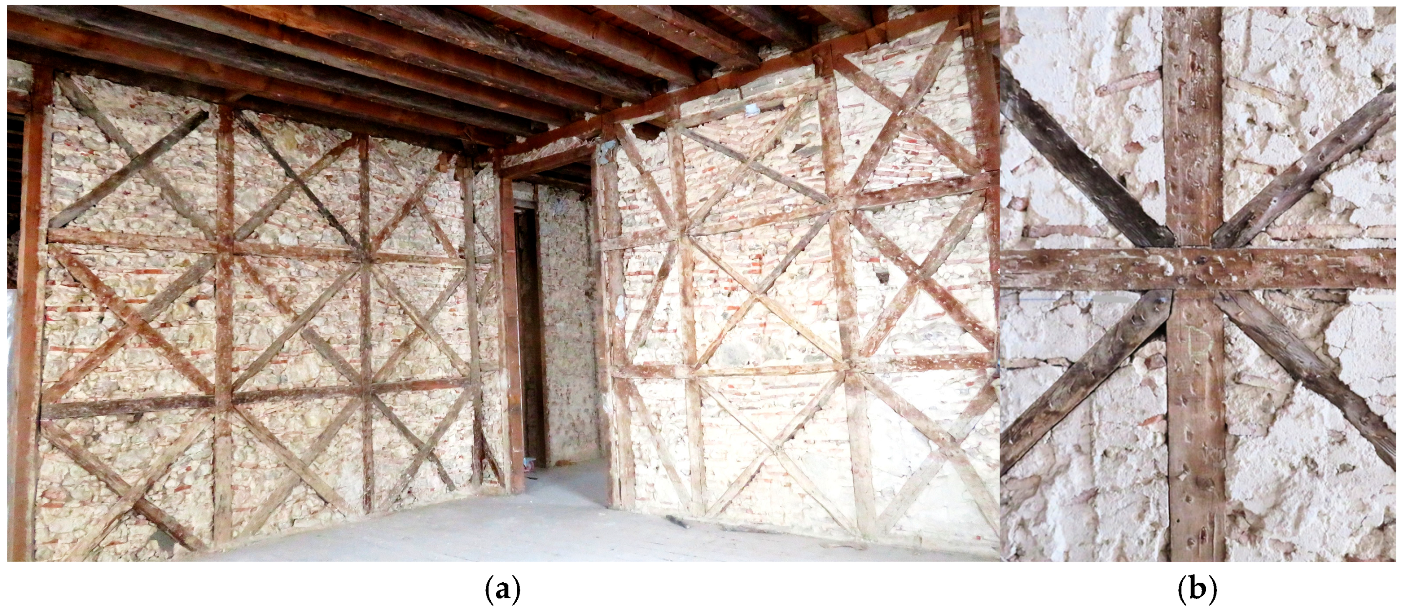
The ‘frontal’ walls are a mixed construction of made of vertical and horizontal wood elements braced with diagonals named St Andrew’s Crosses with masonry infilled [13]. At the second quarter of VIII century, they became the main internal dividing walls of housing buildings. The most common type of construction is the woven front, made up of (0.10 to 0.15) m × (0.08 to 0.10) m sectional beams, fitted and nailed to the floor, and ceiling joists at a distance of around 1 m [4]. The formation of triangles by the St Andrew’s crosses guarantees the structure’s inability to be deformed and its ability to withstand an earthquake [14,18,26]. The height of the ceiling is divided into equal parts and horizontal beams are laid plumb to plumb. Diagonal struts are inserted in the rectangles formed between the props and the beams (Figure 2). The beam located under the floor joist is also known as a ‘frechal’ [15].
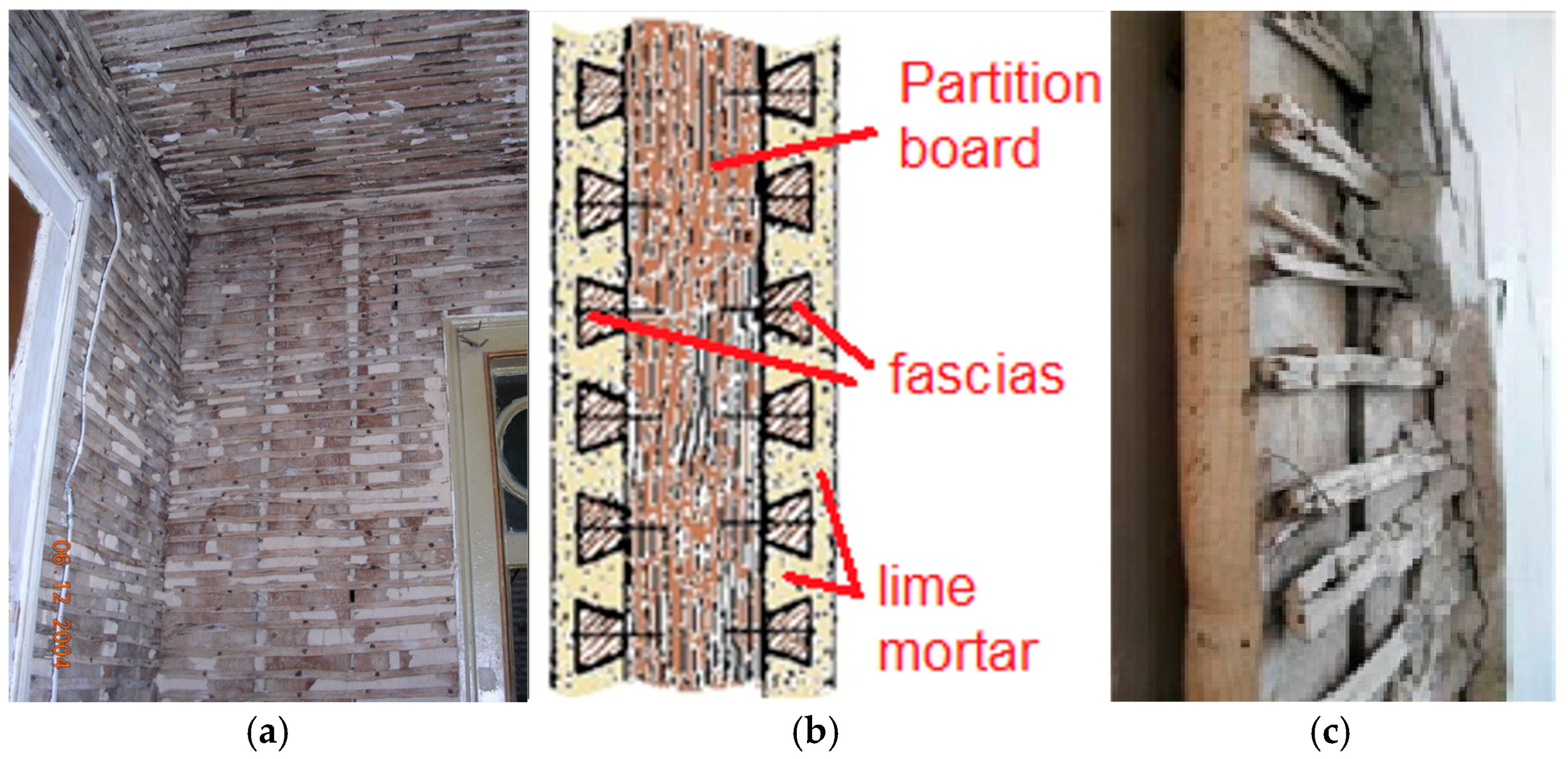
To improve the adhesion and function of the joint between the coating mortar and the wood, the surface of the wood faces was chipped (Figure 2b) and the fascias were nailed at intervals to create an uneven surface through which the mortar was introduced. This joint is essential to ensure the mobilisation of shear strength between materials with such different physical–mechanical properties [15]. Fascias were used to finish the front walls, partitions or ceilings (Figure 3).
Partitions are the secondary internal walls and can be found in all types of buildings. They are generally thin, no more than 0.10 m, sit on floors or walls and, if they are arranged vertically, make the building more resistant to earthquakes. In general, the partition wall was built after the floor beams [31,32].
The so-called simple partition generally consisted of a series of planks, not cleaned or planned, on the inside, spaced at least 1 cm apart and nailed at the top to rails fixed one to the floor and the other to the ceiling. Orthogonally, the trapezoidal fascias are nailed with their smaller side to the partition boards [15,31,32], shown in view and in detail in Figure 2.
The final finish was a lime mortar applied to the face and interstices of the fascias to increase the resistance of the bond to traction and cutting [29,31]. Fascias were also applied under the floor joists to form the ceilings, using the same technique as for the walls [15].

3.2. Timber in Floors

The floor system consists of parallel main beams, with a spacing of 0.30 to 0.40 m, as evidenced in meticulously constructed buildings. During the 19th century, however, building practice moved towards narrower beams with greater spacing (0.50 to 0.60 m) [4].
The author of [4] also points out that the limitations imposed by the size of the forest specimens led to a preference for profiles with a height of 0.20 m or less, which limited the span that could be covered by these simple elements to around 4 m. Often, especially in ‘Pombalino’ construction, the beams were laid on ‘wall plate’, crowning the internal walls (‘frontal’ or partition walls), or embedded in the external walls close to the inner face [32] (Figure 4a). A simpler solution, later adopted, consisted of placing the beams in openings in the external walls, which, in the case of irregular stone masonry, included a trimmed block placed on the lower side of the opening to promote the distribution of loads within the masonry.
The floors were attached to the beam by means of small crosspieces, fitted in a straight line and nailed to it, with a height equal to that of the beam (Figure 4). Their function was to prevent the beams from buckling or swaying and to lock them in place. For spans of 4 m or more, a spacing of half the span was used, and for longer spans, spacing every 2.50 m was used [33].

3.3. Timber in Roof Structures

Trusses, obtained by triangulating elements that are simply joined together, are the most common type of structure and adapt well to different roof geometries. For example, starting from a symmetrical gable truss, it has been possible to adapt it for lanterns, dormers and mansards or to section it at the top and sides to adapt it to multi-gabled roofs [4].
In the simplest cases, trusses are made up of a triangular set of different elements called rafters, struts, purlins, the tie beam and the king post (Figure 5). In the simple roof trusses, the tie beam is always horizontal, rafters connect on the tie beam in an inclined position to form the roof slopes, the king post is clamped vertically by the struts at the apex of the roof and the struts are inclined and connect the legs to the pendant. In single-member trusses, the most prevalent rafter and tie-beam carpentry connection is the ’front notch connection’, which involves a V-shaped indentation in the upper face of the tie beam, wherein the notched end face of the rafter is positioned [32,34].
In Figure 4, an example of the most traditional roof truss is shown.

4. Understanding the State of Conservation

4.1. Structural or Functional Capacity

Recognising the structural or functional capacity of a wooden structure is fraught with difficulties related not only to the characteristics of the material (anisotropy, variability, and hygroscopicity) [9,10,35] but also to the possibility that its mechanical properties may be reduced by degradation effects, particularly biological degradation [9,12]. For this reason, inspection, diagnosis, assessment and intervention design is a process that must be carried out in a systematic and expert manner [36].

4.2. Inspection and Diagnosis by Visual Analysis

The first step in inspecting the state of preservation of wood is visual analysis. This analysis makes it possible to conduct an initial diagnosis detecting surface degradation due to biological agents, visible mechanical damage and situations where moisture has penetrated the structure, which have occurred in the past or are still active today [9,12]. Therefore, after a general analysis, a more detailed analysis should be carried out, focusing on timbers that raise the most doubts about their state of conservation [4,12,37]. After the necessary cleaning of the element, the wood is pressed with a sharp object, first on visibly healthy wood to identify the surface characteristics and then on areas that appear to be degraded [36,38]. This can detect decay caused by fungus, woodworms or subterranean termites [9,38].
In the latter two cases, the agents degrade the wood under an intact film, so the element may appear healthy to the eye. Similarly, the aim is to identify the depth and extent of the degraded wood.
As the most common cause of degradation in timber structures is the action of biological agents [9], the morphology of degradation by the main biological agents and their main consequences are presented below:
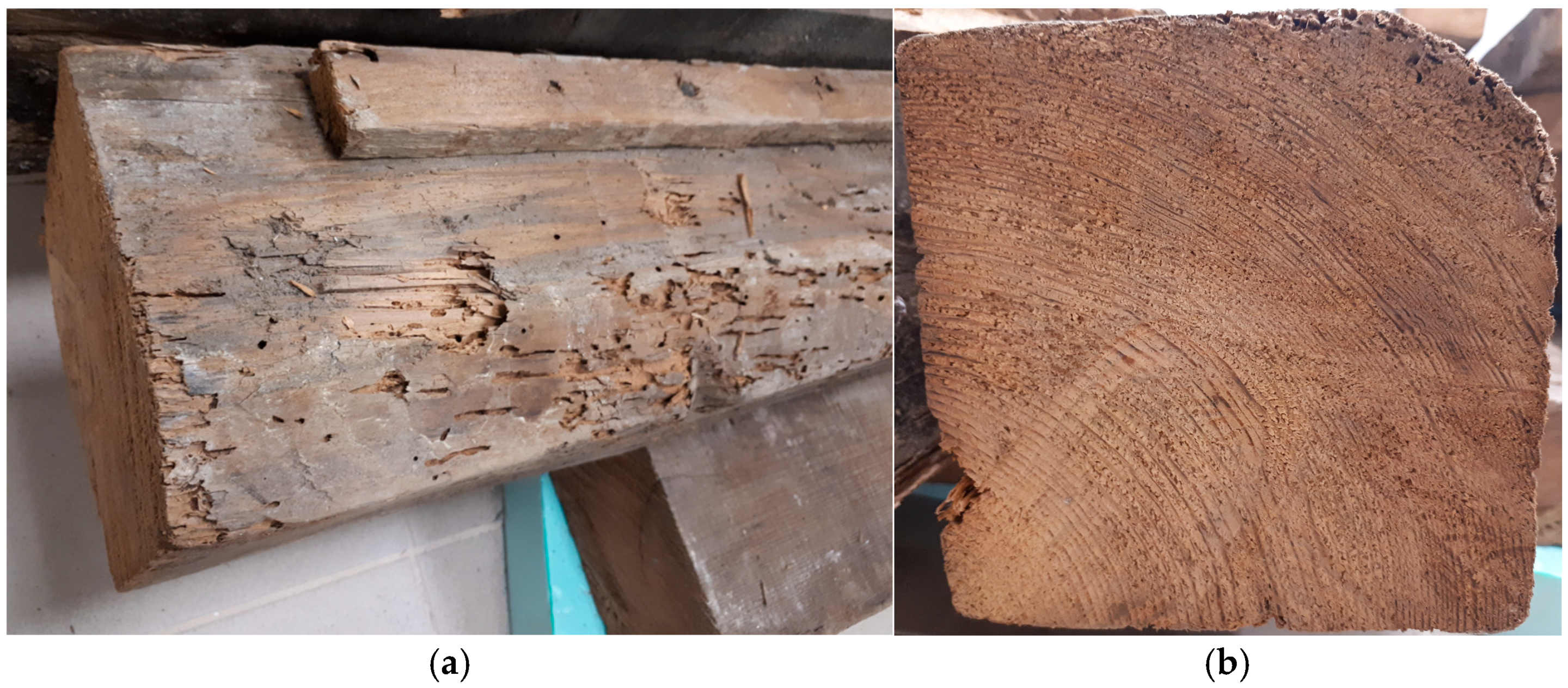
  • Woodworm or beetle damage—This is usually found along the entire length of the element, with the main signs being holes in the surface (round and numerous in the case of small woodworms, and oval and few in the case of large woodworms) and sawdust pushed outwards in the case of small woodworms [9,38]. Often, especially in the case of large beetle infestation, this is only superficial, and it is possible to identify the area of galleries by identifying a section of healthy wood underneath. Figure 6 shows one of these cases with a beam from a ‘Pombaline’ building: although the external appearance is considerably degraded by small woodworms (Figure 6a), the degraded layer is only a few millimetres deep (Figure 6b) [38]. The reduction in the wood’s resistance is the result of a physical reduction in the cross-section of the material due to the opening of galleries by the larvae. If the galleries are at a shallow depth, a reduced (effective) cross-section can be estimated [12]. In other cases, the attack may take the form of diffuse damage to the cross-section, mainly in the sapwood, with no apparent loss of the cross-section. In these cases, a reduction in mechanical properties and density can be expected [12,39,40];
  • Fungal decay—This occurs only in wood that has been exposed to prolonged moisture and is more common near exterior walls, under eaves and in contact with the ground. The wood appears soft, wrinkled and/or with deep and numerous cracks, and brown or whitish filaments (hyphae) can often be seen on the surface [9]. The loss of mechanical strength is the result of the chemical modification of the wood cells, which generally results in a large loss of mass and strength [38,41]. The affected volume can be assessed by NDT to determine whether there is healthy wood in the section. However, due to the high degree of uncertainty about the resistance of apparently healthy wood, it is common in practice to assume that its contribution is insignificant and opt to replace the degraded areas. If the deterioration is incipient and appears to affect only the surface of the member, it may be retained, provided it is reinforced or strengthened [35,38].
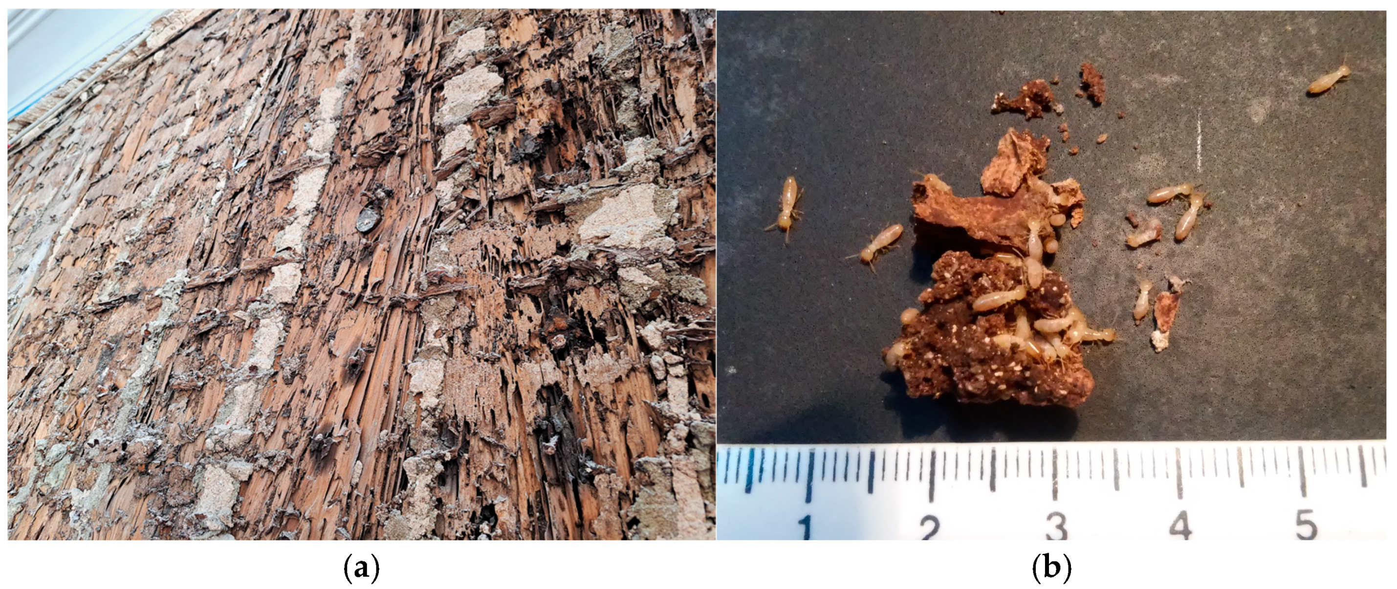
  • Subterranean termite (Reticulitermes grassei) attack—This occurs only in damp wood and is more common in areas of rising humidity, in contact with the ground or under gutters. The wood is veneered and usually has earthy concretions inside (Figure 7a,b). Subterranean termites eat away at the wood under an intact surface, but without any resistance to the tip of a sharp object, causing a significant physical loss of material throughout the section, which almost always results in the complete replacement of the damaged parts [9,33,38].

4.3. Auxiliary Diagnostic Equipment

For a more in-depth analysis, it is necessary to use auxiliary diagnostic equipment by means of SDT or NDT methods [35,37]. These include instruments for measuring drilling resistance, which, thanks to the information they provide on the wood’s greater or lesser resistance to the advance of the drill at depth, can detect altered areas of the element that are not visible on the surface or, on the other hand, the depth of degradation visible on the surface. This makes it possible to define the effective cross-section, i.e., the part of the cross-section of a degraded timber member that is presumed to have a commensurate load-bearing capacity with that of other non-degraded members [12]. Instruments using a 6-joule impact pin for measuring penetration resistance are useful. These instruments are easy to use and can perform many tests on each piece of wood. The penetration resistance value indicates the state of surface degradation of the wood and/or its properties, as determined through correlation studies [37].

5. Resistance Capacity Assessment

As previously mentioned, the intention behind any strength assessment is to preserve as much historic structural timber as possible [12]. However, it should be noted that the wood group includes materials that are profoundly different from each other. The density of these materials can vary from around 350 kg/m3 to more than three times that value, and their characteristic flexural strength values can vary from 14 to 70 MPa [35]. Due to this great variability and the usual lack of information on the characteristics and actual mechanical strength values of the wood in an old building, it is necessary to follow a list of checks which, point by point, will provide complementary information that can provide some degree of certainty about the structural system [35].

5.1. Species and Grades

Visual strength grading (VSG) provides a consistent method for assessing the strength of timber for structural use, depending on the identification of the species or combination of species and the geographical growth area of the trees from which the timber is sawn [10,41]. The EN 1912:2024 [42] standard lists the visual strength grades, species and sources of wood and specifies the strength classes to which they are assigned. Each strength class corresponds to characteristic values of mechanical strength, stiffness and density in accordance with EN 338:2016 [43], regardless of the original wood species (Figure 8) [35,44].
A strength class is simply a group of strength grade combinations that have similar properties. There are twelve strength classes for softwoods ranging from C14 to C50 and there are six strength classes for hardwoods ranging from D30 to D70. The numbers represent bending stress for each class; the higher the number, the stiffer and stronger the timber in relation to its cross-sectional area.
The VSG methods are based on rules published by standards of each country or combinations of countries, limiting the maximum and minimum values for defects and characteristics of each structural piece of wood. Usually, the criteria for visual strength grading remain much the same for softwoods and hardwoods, although tolerances (and thus confidence limits) vary according to the grade at which the timber is assessed. The common criteria are Rate of Growth, Slope of Grain, Knots, Fissures, Wane, Resin and Bark Pockets, Distortion, Insect Damage and Rot. All are assessed during the VSG process for each piece of timber inspected [35,44].

5.2. Recognition of Physical–Mechanical Properties

The strength classes can be adopted by VSG methods, by estimating reference properties, or by using both methods [35,45].
Thus, as widely advocated in the literature [11,37,46], the values to be adopted for the reference properties of structural timber elements are obtained (density, the modulus of elasticity and flexural strength) [10,45]. This is achieved by combining the use of non-destructive, semi-destructive and/or destructive techniques, which generally consist of readings obtained from instruments measuring resistance to drilling, resistance to penetration, ultrasound, various sonic-based techniques, imaging or a range of other means [11,19,20,45].
It is generally considered good practice to use more than one method, combining direct and indirect methods to achieve redundancy or correlation between the measurements obtained [10,46]. An approach to combining measurements is presented in Section 6.

6. Laboratory and In Situ Approach with Penetration Resistance Testing

This section presents the development of research into the reliability of penetration resistance measurements using a 6-Joule instrument for estimating the density of old wooden elements. This approach is part of an extensive laboratory campaign using a combination of SDT/NDT methods carried out by the author and her support team at the Wood Laboratory of ISEL—Instituto Superior de Engenharia de Lisboa.
The laboratory research study resulted in a pattern corresponding to the correlation between the wood’s density and the readings obtained from the needle penetration resistance test. To verify the pattern obtained in real cases, it was applied to structural working timber elements with different load levels and functions, together with the extraction of a wood core in the same area.

6.1. Materials and Methods

6.1.1. Wood Tested in Laboratory

From a set of wooden structural elements collected from Pombaline buildings in the Lisbon region, five beams of Scots pine (Pinus sylvestris, L.) were selected (Figure 9a). They were then cut into 25 × 55 × 200 mm specimens and stabilised in a conditioned atmosphere at RH = 65 ± 5% and T = 20 ± 2 °C [23]. Following the process of stabilisation, the mass and dimensions of each specimen were measured, and their density was calculated based on an average water content of 12% (Figure 9b).
As the beams were old and had been cut by hand, there were many irregularities on the faces, as well as some cracks, biological deterioration and iron nails. All specimens with any defects were considered unsuitable for testing (Figure 9c). Therefore, prior to the tests, approximately two thirds of the cut specimens were rejected. So, 68 specimens were considered suitable for testing [24].
The NDT instrument Pilodyn® 6J was used to obtain penetration resistance results. In each specimen, three pin impacts were applied to the larger side and a further three to the smaller side. The results obtained for each specimen were recorded as the depth in mm that the pin penetrated the wood. The criterion of excluding a reading with a difference in more than 2 mm to the nearest value was used and a new reading was taken instead. The average of each group of readings was then calculated for each specimen [24].

6.1.2. Timber Tested In Situ

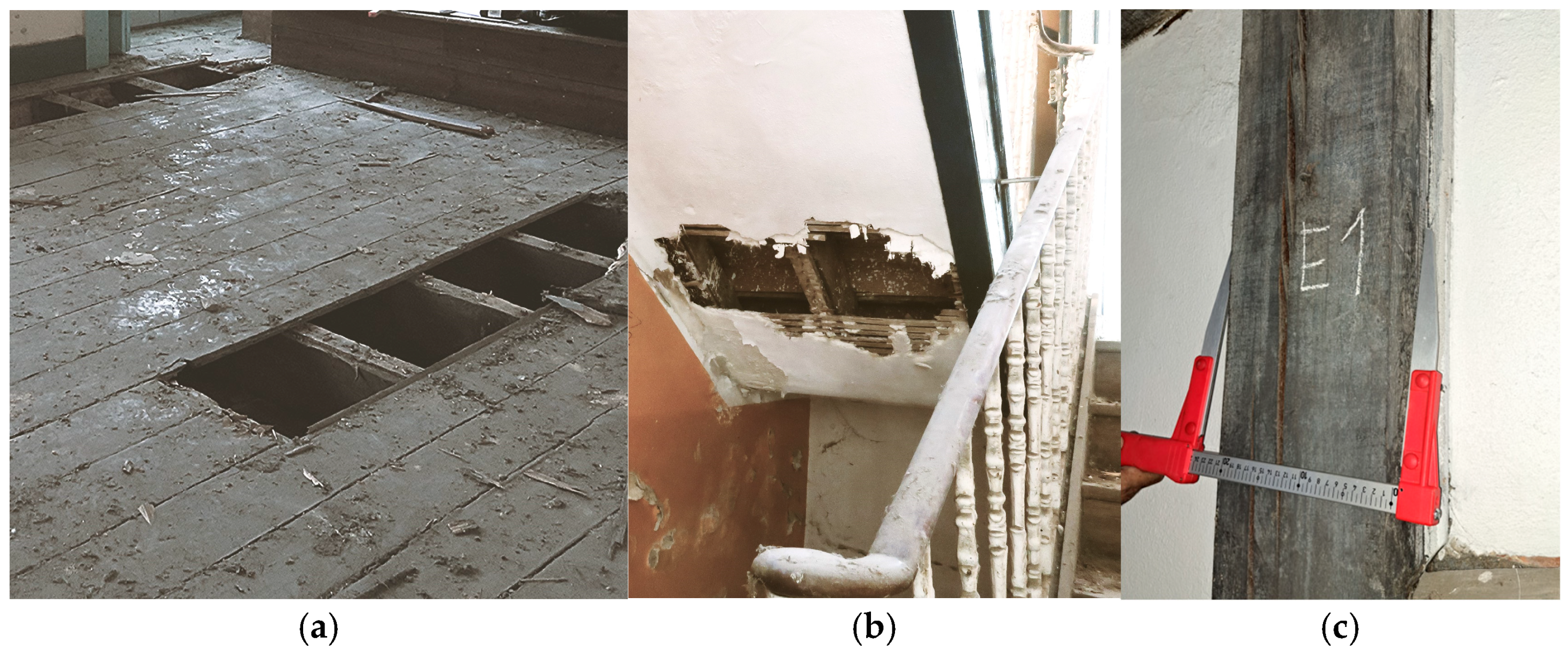
The in situ tests are the central objective of this project, because the aim of this study is to find a pattern that can be used in practical situations. The campaign was carried out in different old buildings. In each building, the elements tested had different functions, such as floor beams, columns, staircase beams and others. As such, they were subjected to different types of loads (Figure 10a–c).
The aim of having great variability in the structural elements tested is to seek the reliability of a pattern that can provide the instrument user with an estimate of the density of Scots pine wood.
Thus, an in situ application campaign of the laboratory results was carried out on four buildings of original construction dating from the 18th to the 20th centuries, located in the historic areas of the city of Lisbon, with the kind support of the company ’Spybuibuilding’. All the buildings were constructed with a mixed structure of masonry and pine wood (Pinus spp.).
The following in situ tests were carried out [24]:
  • The determination of the water content of the wood element, as well as the RH and temperature values at the test locations.
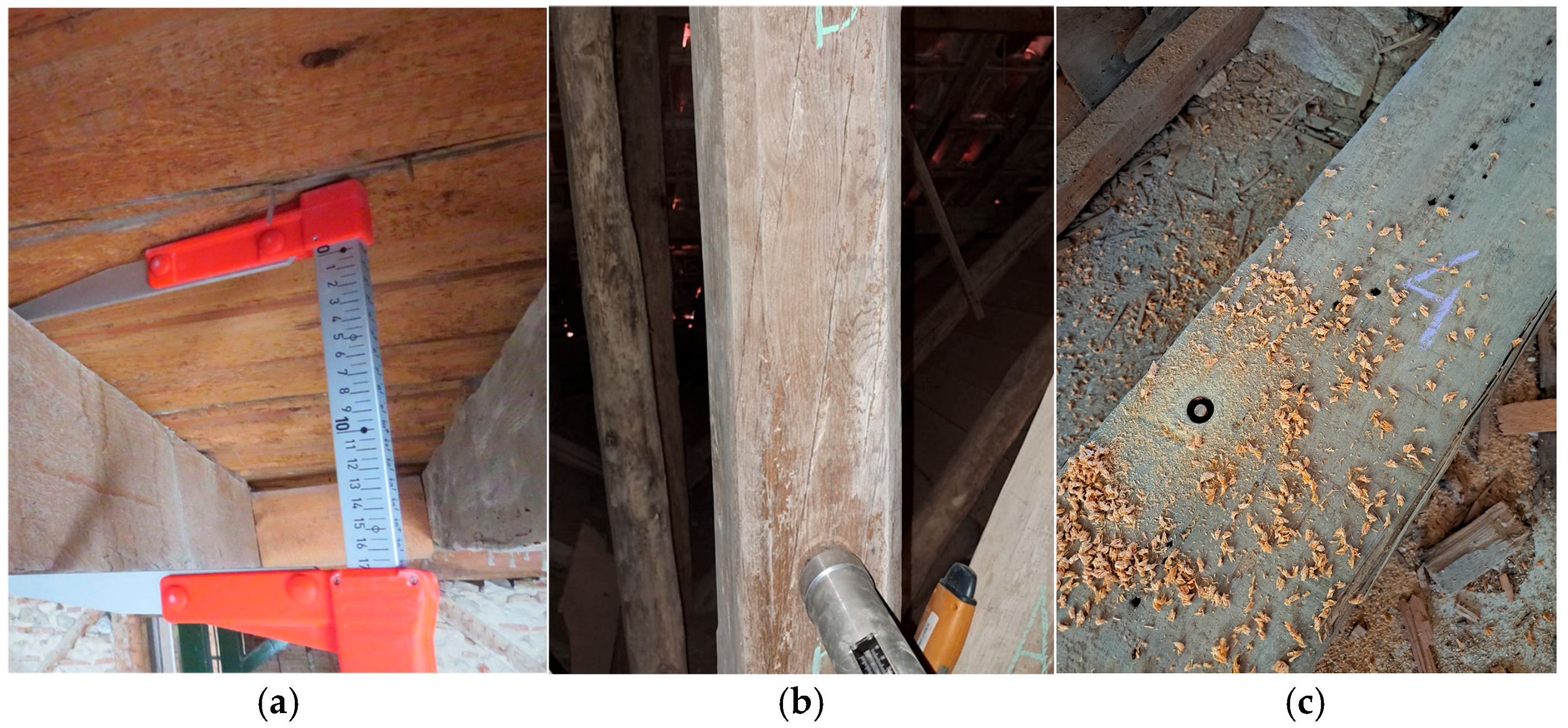
  • The identification of the geometric conditions and state of conservation of the structural elements (Figure 11a).
  • The characterisation of the surface’s hardness with Pilodyn® (Figure 11b).
  • Wood core extraction for the laboratory study and the correlation with values estimated indirectly from Pilodyn® measurements (Figure 11c).
  • Eighteen wood cores in good condition, 7 mm in diameter and up to 120 mm long, were extracted for this study in the vicinity of the resistance to penetration tests.

6.2. Results and Discussion

6.2.1. Wood Tested in Laboratory

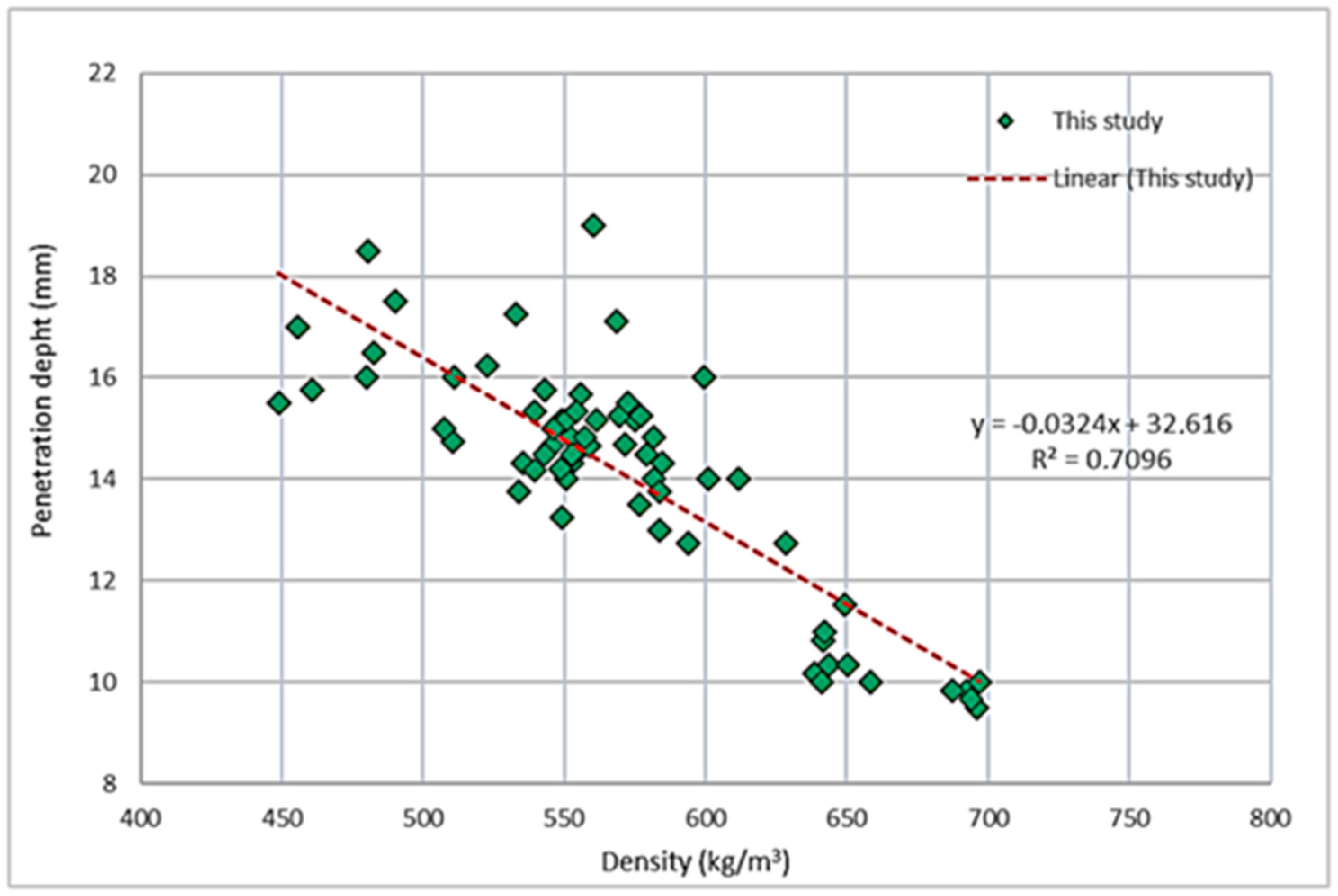
A scatter plot was constructed utilising the mean of six penetration depth measurements and the density of each specimen (n = 68). A linear correlation was identified as the most suitable fit for the observed outcomes. The calculation of the correlation gave a coefficient of determination (R2) of 0.71, indicating a reasonable to good relationship for the wood material (Figure 12)
The correlation between density and the Pilodyn readings is presented in Equation (1)
D e p t h i = 0.0324   ρ i + 32.616         ( kg/m 3 )
where
-
ρi—density of reading i.
-
Depthi—Pilodyn® reading i.
The results obtained with this laboratory study are compared with the results obtained by authors of the references mentioned below.
Table 1 presents the linear regression coefficients obtained by other authors for correlations between the density of the wood and the readings obtained with the Pilodyn® 6J instrument. Although slightly lower, it is considered that there is good agreement between the values of R2 obtained in this study and those presented.

6.2.2. Wood Obtained In Situ and Tested in the Laboratory

A sensitive study was carried out to compare the density values obtained from the indirect method (correlation) and the direct method (wood core measurement).
Therefore, the in situ density was determined at two levels:
  • Indirect method—based on the results of in situ penetration resistance tests, calibrated by the density values obtained from the laboratory study;
  • Direct method—based on wood core extraction and measurement.
The laboratory data for the eighteen extracted cores were obtained by measuring their dimensions and mass after stabilisation. The density of each core could then be compared with the density values estimated from the average of the Pilodyn® test values in the vicinity.
The wood penetration resistance values measured in the real environment were corrected to 12% water content using the empirical expression published in [24] to make a correct comparison with the reference values.
There was a very high degree of agreement between the density estimated by the in situ Pilodyn® measurements and the real density of each core, with an average difference of 5.2 ± 4.1% [24].

7. Conclusions

With this article, we believe we have been able to explain why there are certain wooden elements in the structures of Pombaline buildings in Portugal. Their main functions have been explained, as well as the reasons why, when these elements are missing or deteriorated, they should be replaced or reinforced. Important information was also provided on how to identify their state of conservation, understanding the cause-and-effect relationship of excessive or a lack of humidity and excessive or a lack of temperature, as well as the effect that these environments can have on the degradation agents of the heartwood and sapwood of each species.
The scientific study presented shows on how the Pilodyn® 6J device can help technicians to indirectly measure the density mass of wooden structural elements in order to carry out safety assessment analyses and thus understand the possibility of maintaining structural elements or the need to reinforce them to the exact extent required. This study showed a very good approximation of 5.2% between the estimated values and the real values, which indicates that this method is very reliable for use in servicing wood, and the pattern given in Equation (1) can be used for estimating wood density.

Funding

This research was funded by Foundation for Science and Technology through grant number UIDB/04625/2020 to the research unit CERIS.

Data Availability Statement

Details of where the data supporting the results generated during the study can be found are not available due to privacy and ethical restrictions.

Acknowledgments

The author would like to thank ISEL’s Civil Engineering Department for encouraging her to carry out research using the Wood Laboratory and the company Spybuilding for providing access to the old buildings.

Conflicts of Interest

The authors declare no conflicts of interest.

Abbreviations

The following abbreviations are used in this manuscript:
NDTNon-destructive testing
SDTSemi-destructive testing
VSGVisual strength grading
JJoules

References

  1. Pinho, F.S.; Henriques, D.; de Brito, J.; Falcão, M.J.; Moura, R.; de Freitas, V.P. Urban rehabilitation in Portugal. Specificities and foundations for a strategic plan. In Proceedings of the 4th CIHEL2017—4th International Congress on Housing in the Portuguese-Speaking Area; University of Beira Interior: Covilhã, Portugal, 2017. (In Portuguese) [Google Scholar]
  2. Brandt-Grau, A.; Pérez-Vitoria, S.; Chapuis, M. Research for Protection, Conservation and Enhancement of Cultural Heritage—Opportunities for European Enterprises; European Commission, Directorate-General for Research and Innovation; Publications Office of the European Union: Strasbourg, France, 2002. [Google Scholar]
  3. Vicente, R.; Ferreira, T.M.; da Mendes Silva, J.A.R. Supporting urban regeneration and building refurbishment. Strategies for building appraisal and inspection of old building stock in city centres. J. Cult. Herit. 2015, 16, 1–14. [Google Scholar] [CrossRef]
  4. Appleton, J. Rehabilitation of Old Buildings. In Pathologies and Intervention Technologies; Orion Editions: Lisboa, Portugal, 2003; 454p. (In Portuguese) [Google Scholar]
  5. International Wood Committee (ICOMOS). Principles for the Preservation of Historic Timber Buildings. In Proceedings of the Adopted by ICOMOS at the 12th General Assembly, Mexico City, Mexico, 17–23 October, 1999. Partially modified by: ICOMOS IIWC (2016). Principles for the Conservation of Wooden Built Heritage. In Proceedings of the Ratified during the 20th IIWC International Conference and Symposium, Falun, Sweden, 13–16 April 2016. [Google Scholar]
  6. Yair, S.; Rokia, R.; Dejan, M. Refurbish or replace? The Life Cycle Carbon Footprint and Life Cycle Cost of Refurbished and New Residential Archetype Buildings in London. Energy 2022, 248, 123585. [Google Scholar] [CrossRef]
  7. Cóias e Silva, V. Structural Rehabilitation of Old Buildings—Masonry/Wood, Minimally Intrusive Techniques; Argumentum and Gecorpa Edition: Lisbon, Portugal, 2007; 379p. (In Portuguese) [Google Scholar]
  8. D’Ayala, D.; Riggio, M. Assessment of Historical Timber Structures: Select Papers from the Second International Conference on Structural Health Assessment of Timber Structures (SHATIS13). Int. J. Archit. Herit. 2015, 9, 639–640. [Google Scholar] [CrossRef]
  9. Cruz, H. Inspection, evaluation and conservation of wooden structures. In Proceedings of the 1st Conference on Materials in Construction, Porto, Portugal, 12 September 2011. [Google Scholar]
  10. Feio, A.; Machado, J.S. In-situ assessment of timber structural members: Combining information from visual strength grading and NDT/SDT methods—A review. Constr. Build. Mater. 2015, 101, 1157–1165. [Google Scholar] [CrossRef]
  11. Machado, J.S.; Riggio, M.; Descamps, T. (Eds.) Combined Use of NDT/SDT Methods for Assessment of Structural Timber Members; COST fp1101 State-of-the-Art Report_TG2 e-book; UMONS—Université de Mons: Mons, France, 2015; ISBN 978 87325 094 2. [Google Scholar]
  12. Cruz, H.; Yeomans, D.; Tsakanika, E.; Macchioni, N.; Jorrisen, A.; Touza, M.; MannuccI, M.; Lourenço, P.B. Guidelines for the on-site assessment of historic timber structures. International. J. Archit. Herit. 2015, 9, 277–289. [Google Scholar] [CrossRef]
  13. Cardoso, R.; Lopes, M.; Bento, R.; D’Ayala, D. Historic, braced frame timber buildings with masonry infill (Pombalino buildings). In World Housing Encyclopedia Report; Earthquake Engineering Research Institute: Oakland, CA, USA, 2003. [Google Scholar]
  14. Cardoso, R.; Lopes, M.; Bento, R. Earthquake resistant structures of portuguese old ‘pombalino’ buildings. In Proceedings of the 13th World Conference on Earthquake Engineering, Vancouver, BC, Canada, 1–6 August 2004. [Google Scholar]
  15. Henriques, D.F.; Silveira, P.M. ‘Pombaline’ and ‘gaioleiro’ construction in the Lisbon area. In Proceedings of the 3rd International Congress on the History of Luso-Brazilian Construction, Salvador, Bahia, Brazil, 3–7 September 2019. [Google Scholar]
  16. Kasal, B.; Tannert, T. (Eds.) State-of-the-Art Report of the RILEM Technical Committee 215-AST. In In Situ Assessment of Structural Timber; Springer: Berlin, Germany, 2010. [Google Scholar]
  17. Dietsch, P.; Köhler, J. (Eds.) Assessment of Timber Structures; Shaker Verlag GmbH: Aachen, Germany, 2010. [Google Scholar]
  18. Silva, V.C.; Gomes, J.V.; Alvarez, M.L.; Domingues, F. Support for structural modelling using non-destructive methods for the retaining walls of the ‘Pombalino’ buildings in Lisbon’s Pombaline quarter. In Proceedings of 2º ENCORE; LNEC: Lisboa, Porturgal, 1994; pp. 127–136. [Google Scholar]
  19. Piazza, M.; Riggio, M. Visual strength-grading and NDT of timber in traditional structures. J. Build. Apprais. 2008, 3, 267–296. [Google Scholar] [CrossRef]
  20. Machado, J.S.; Riggio, M.; Descamps, T. (Eds.) Reliability of prediction by combining direct and indirect measurements. In Combine Use of NDT/SDT Methods for Assessment of Structural Timber Members; COST fp1101 State-of-the-Art Report_TG2 e-book; UMONS—Université de Mons: Mons, France, 2015; pp. 1–13. ISBN 978 87325 094 2. [Google Scholar]
  21. Morales-Conde, M.J.; Rodríguez-Liñán, C.; Saporiti-Machado, J. Predicting the density of structural timber members in service. The combine use of wood cores and drill resistance data. Mater. Construcción 2014, 64, e029. [Google Scholar] [CrossRef]
  22. López, G.; Vallelado-Cordobés, P.; Gómez-Royuela, J.L.; Basterra, L.-A. Diagnosis and assessment of a historic timber structure in La Casa del Corregidor, using non-destructive techniques. Case Stud. Constr. Mater. 2023, 19, e02311. [Google Scholar] [CrossRef]
  23. Machado, J.S.; Pereira, F.; Quilhó, T. Assessment of old timber members: Importance of wood species identification and direct tensile test information. Constr. Build. Mater. 2019, 207, 651–660. [Google Scholar] [CrossRef]
  24. Henriques, D.F. Recognizing of timber in old buildings: Density estimation by penetration resistance testing. In Proceedings of the REHABEND 24—Construction Pathology, Rehabilitation Technology and Heritage Management, Gijon, Spain, 7–10 May 2024; pp. 541–550. [Google Scholar]
  25. Ronca, P.; Gubana, A. Mechanical characterisation of wooden structures by means of an in situ penetration test. Constr. Build. Mater. 1998, 12, 233–243. [Google Scholar] [CrossRef]
  26. Notivol, E.; Gil, L.A.; Pardos, J.A. Wood specific gravity and variability estimation in Pinus pinaster Ait. Trees. For. Syst. 1992, 1, 41–47. [Google Scholar] [CrossRef]
  27. Kouris, L.A.S.; Kappos, A.J. Detailed and simplified non-linear models for timber-framed masonry structures. J. Cult. Herit. 2012, 13, 47–58. [Google Scholar] [CrossRef]
  28. Stellacci, S.; Rato, V. Timber-Framing Construction in Herculaneum Archaeological Site: Characterisation and Main Reasons for its Diffusion. Int. J. Archit. Herit. 2019, 15, 1301–1319. [Google Scholar] [CrossRef]
  29. Silveira, P.; Veiga, R.; de Brito, J. Plastered Walls in Old Buildings. In 3rd ENCORE—Meeting on the Conservation and Rehabilitation of Buildings; National Civil Engineering Laboratory: Lisbon, Portugal, 2003. [Google Scholar]
  30. Oliveira, C.; Cabrita, A. Typification of the housing stock. In 1st Meeting on the Conservation and Rehabilitation of Residential Buildings; National Civil Engineering Laboratory: Lisbon, Portugal, 1985. [Google Scholar]
  31. Leitão, L. Elementary course in construction. In Prepared According to the Programme of the Central School of Engineering; National Press: Lisbon, Portugal, 1896. [Google Scholar]
  32. Costa, P. Enciclopédia Prática da Construção Civil; Portugália Editora: Lisbon, Portugal, 1955. [Google Scholar]
  33. Branco, J.P. Carpentry Work in Civil Construction, 2nd ed.; Escola Profissional Gustave Eiffel Editions: Lisbon, Portugal, 1993. [Google Scholar]
  34. Palma, P.; Garcia, H.; Ferreira, J.; Appleton, J.; Cruz, H. Behaviour and repair of carpentry connections—Rotational behaviour of the rafter and tie beam connection in timber roof structures. J. Cult. Herit. 2012, 13, S64–S73. [Google Scholar] [CrossRef]
  35. Machado, J.S.; Dias, A.; Cruz, H.; Palma, P. Avaliação, Conservação e Reforço de Estruturas de Madeira; Edições Verlag-Dashofer: Lisbon, Portugal, 2009. [Google Scholar]
  36. Michal, K.; Jiří, K.; Jaroslav, H.; Marek, E.; Petr, R. Time demands of traditional hand-hewing techniques for sustainable repair of wooden heritage structures: A comparative study. J. Cult. Herit. 2024, 66, 197–203. [Google Scholar] [CrossRef]
  37. Arriaga, F.; Peraza, F.; Esteban, M.; Bobadilla, I.; Garcia, F. Intervención en Estructuras de Madera; AITIM—Asociación de Investigación Técnica de las Indústrias de la Madera y Corcho: Madrid, Spain, 2002; 466p. [Google Scholar]
  38. Henriques, D.F. Wood in old buildings: Conserve, reinforce or replace? In Proceedings of the International Conference on the Rehabilitation of Old Masonry Structures, Order of Engineers, Lisbon, Portugal, 5 July 2018. [Google Scholar]
  39. Verbist, M.; Branco, J.M.; Nunes, L. Characterization of the Mechanical Performance in Compression Perpendicular to the Grain of Insect-Deteriorated Timber. Buildings 2020, 10, 14. [Google Scholar] [CrossRef]
  40. Nocetti, M.; Aminti, G.; Marco, D.I.; Michele, B. Geometric representation of the irregular cross-section of old timber elements: Comparison of different approaches for mechanical characterization. Constr. Build. Mater. 2021, 304, 124579. [Google Scholar] [CrossRef]
  41. Henriques, D.F.; Appleton, V. Rehabilitating structural timber in old buildings. In Proceedings of the CLB-MCS 2018, 3rd Luso-Brazilian Congress, Sustainable Construction Materials, Coimbra, Portugal, 14–16 February 2018. [Google Scholar]
  42. EN 1912:2024; Structural Timber-Strength Classes-Assignment of Visual Grades and Species. CEN: Brussels, Belgium, 2024.
  43. EN 338:2016; Structural Timber-Strength Classes. CEN: Brussels, Belgium, 2016.
  44. Nocetti, M.; Aminti, G.; Vicario, M.; Brunetti, M. Mechanical properties of ancient wood structural elements assessed by visual and machine strength grading. Constr. Build. Mater. 2024, 411, 134418. [Google Scholar] [CrossRef]
  45. Michal, K.; Miloš, D.; Machado, J.S.; Piazza, M.; Yamaguchi, N. Prediction of mechanical properties by means of semi-destructive methods: A review. Constr. Build. Mater. 2015, 101, 1215–1234. [Google Scholar] [CrossRef]
  46. Henriques, D.F.; Nunes, L.; Machado, J.S.; de Brito, J. Timber in buildings: Estimation of some properties using Pilodyn® and Resistograph®. In Proceedings of the XII DBMC—International Conference on Durability of Building Materials and Components, Porto, Portugal, 12–15 April 2011; pp. 949–956. [Google Scholar]
  47. Branco, J.M.; Piazza, M.; Cruz, P.J.S. Structural analysis of two King-post timber trusses: Non-destructive evaluation and load-carrying tests. Constr. Build. Mater. 2010, 24, 371–383. [Google Scholar]
  48. Feio, A.O. Inspection and Diagnosis of Historical Timber Structures: NDT Correlations and Structural Behaviour. Ph.D. Thesis, University of Minho, Braga, Portugal, 2006. [Google Scholar]
  49. Cavalli, A.; Togni, M. How to improve the on-site MOE assessment of old timber beams combining NDT and visual strength grading. Nondestruct. Test. Eval. 2013, 28, 252–262. [Google Scholar] [CrossRef]
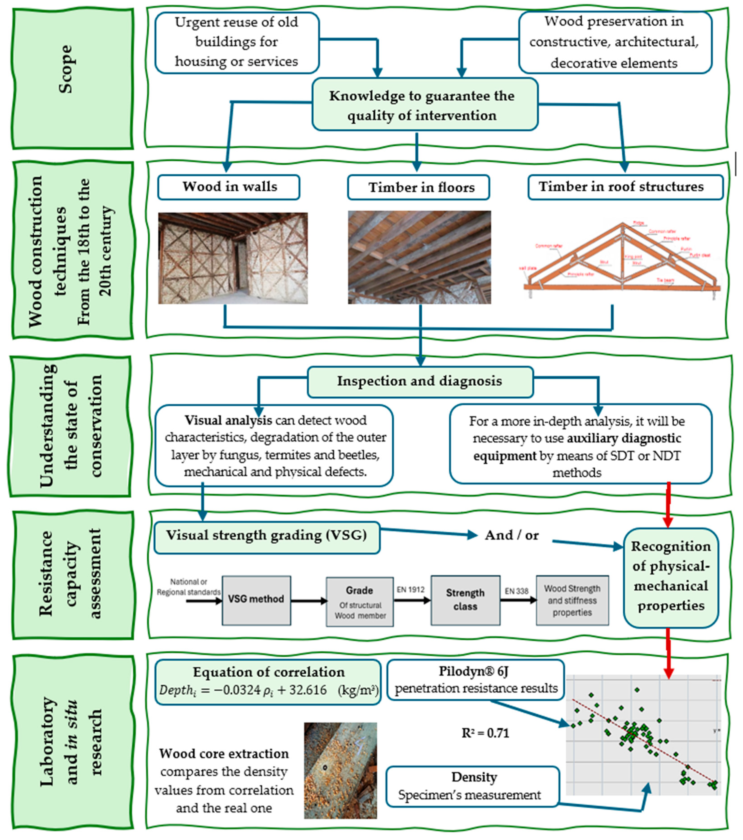
Figure 1. A flowchart of the sequence of subjects covered in this article and their interrelationship.
Buildings 15 01161 g001
Figure 2. Examples of ‘frontal’ walls in view and in detail. (a) ‘Frontal’ walls in an 18th century building (source: author’s collection); (b) detail of a ’frontal’ wall knot with chipped timbers (source: author’s collection).
Buildings 15 01161 g002
Figure 3. Partition walls. General views and details. (a) Fascias in walls and ceilings (source: author’s collection); (b) schematic representation of a simple partition wall section (adapted from [29]); (c) simple partition wall section with fascias in chestnut arch (source: author’s collection).
Buildings 15 01161 g003
Figure 4. Floor beams, properly doweled (source: author’s collection). (a) View of the floor structure resting on ‘wall plate’ after the ceiling has been removed; (b) Floor structure after the floor has been removed.
Buildings 15 01161 g004
Figure 5. Representation of a traditional King post roof truss (source: adapted from [33]).
Buildings 15 01161 g005
Figure 6. Structural element degraded by woodworm (source: author’s collection). (a) External appearance of structural element; (b) internal appearance of section.
Buildings 15 01161 g006
Figure 7. Appearance of wood degraded by subterranean termites (source: author’s collection). (a) Decayed partition wall along its entire length after cladding has been removed; (b) Subterranean termite (removed from habitat) appearance and size.
Buildings 15 01161 g007
Figure 8. Sequence of application of VSG method and assignment of grades to strength classes (source: author’s collection).
Buildings 15 01161 g008
Figure 9. Laboratory material for testing (source: author’s collection). (a) Two of selected beams; (b) some of selected specimens; (c) example of unsuitable specimens.
Buildings 15 01161 g009
Figure 10. In situ tested members (source: author’s collection). (a) Floor beams; (b) staircase rafters; (c) column.
Buildings 15 01161 g010
Figure 11. In situ inspection procedures (source: adapted from [33]). (a) Geometric survey of the timber elements; (b) resistance to penetration test; (c) core extraction.
Buildings 15 01161 g011
Figure 12. Results of penetration resistance versus density.
Buildings 15 01161 g012
Table 1. Determination coefficients from linear regression analysis between Pilodyn® 6J results and wood density by several authors.
Identification of Timber Species TestedYear of PublicationDetermination Coefficient, R2AuthorsReference
Several timber species19780.74 a 0.92GorlacherGorlacher, cited by [47]
Pinus pinaster19920.73Notivol et al.[26]
Oak timber20060.91Feio[48]
Pinus sylvestris and Pinus pinaster20110.80Henriques et al.[46]
Abies alba20130.78Cavalli & Togni[49]
Pinus sylvestris and Pinus pinaster20240.74Henriques[24]
Disclaimer/Publisher’s Note: The statements, opinions and data contained in all publications are solely those of the individual author(s) and contributor(s) and not of MDPI and/or the editor(s). MDPI and/or the editor(s) disclaim responsibility for any injury to people or property resulting from any ideas, methods, instructions or products referred to in the content.