Article

Approximate Analytical Algorithm for Pull-Out Resistance–Displacement Relationship of Series—Connected Anchor Plate Anchorage System

College of Civil Engineering, Hunan University of Technology, Zhuzhou 412007, China
*
Author to whom correspondence should be addressed.
Buildings 2025, 15(7), 1177; https://doi.org/10.3390/buildings15071177
Submission received: 4 March 2025 / Revised: 26 March 2025 / Accepted: 28 March 2025 / Published: 3 April 2025
(This article belongs to the Special Issue Research on Structural Analysis and Design of Civil Structures)

Abstract

:
To improve the pull-out bearing capacity of the anchor plate support system, a support system with series-connected anchor plates was proposed. Based on the Winkler foundation model, a theoretical analysis method for the pull-out resistance–displacement relationship of the series-connected rectangular anchor plates was established through the force equilibrium and displacement continuity conditions. The model experiment of square anchor plates buried in cohesive soil was carried out, and using FLAC3D.6.0 software, a numerical simulation model of the anchor plate was established. Combining the experimental and simulation results, the approximate analytical solutions for the pull-out resistance–displacement relationship of the series-connected square anchor plates were obtained. The on-site experimental results concerning the pull-out resistance–displacement relationship of anchor plates from three engineering cases indicate that the pull-out bearing capacity of the anchor plate, as obtained by the C and M methods in this paper, surpassed the measured capacity. Furthermore, the application of the T-method was considered more rational. The research also indicates that the critical depth between deep- and shallow-buried anchor plates is approximately 4b; for series-connected square anchor plates, to avoid diminishing the pull-out bearing capacity of the support system, the minimum spacing between adjacent plates should satisfy L ≥ 4b.

1. Introduction

As a component capable of effectively providing pull-out bearing capacity, anchor plates offer an efficient solution for supporting and stabilizing both onshore and offshore geotechnical engineering. Vertical anchor plates provide horizontal resistance, thereby being commonly used in retaining systems. The vertical anchor plate generates horizontal resistance to offset the active earth pressure acting on the supporting structure, thus ensuring the equilibrium and stability of the soil mass behind the wall (Randolph et al. (2017) [1]; Das et al. (2013) [2]). Anchor plates have broad applicability and easily combine with other structures, which leads to the innovation of various new forms.
In recent decades, numerous researchers have extensively explored the pull-out behavior of anchor plates. For instance, Murray et al. (1989) [3], Ilamparuthi et al. (2002) [4], Gaudin et al. (2006) [5], Liu et al. (2012) [6], and Han et al. (2016) [7] investigated the pull-out bearing mechanisms through small-scale indoor model experiments. Other researchers, such as Basudhar et al. (1995) [8], Khatri et al. (2011) [9], Kumar (2002) [10], Merifield et al. (2001, 2003, 2005) [11,12,13], Bhattacharya et al. (2014) [14], and Sahoo et al. (2018) [15], utilized the upper and lower bound theorem and the associated flow rule of plastic limit analysis to establish theoretical analysis methods for the ultimate pull-out bearing capacity and explore the failure mechanisms of the anchor plate. Xu et al. (2007,2012) [16,17], conducted an analysis by combining the empirical mode decomposition method with the peak amplitude sequence method. Bu et al. (2024) [18] established a numerical model using the CANNY program and validated it against the experimental results. Ghaly et al. (1994) [19], White et al. (2008) [20], and Tho et al. (2014) [21] utilized the limit equilibrium theory and numerical simulations to analyze the characteristics of the pull-out bearing capacity and develop methods for its calculation.
To summarize, the majority of previous studies have concentrated on investigating the ultimate pull-out bearing capacity of the anchor plate. Few studies have addressed algorithms for analyzing their pull-out resistance–displacement relationship. The anchor plate involves soil–structure interaction and must ensure that the transferred load does not exceed the soil resistance at the ultimate state. Simultaneously, under normal serviceability conditions, the displacement of the anchor plate and the deformation of the soil do not exceed the permissible range. The mathematical expression of the pull-out resistance–displacement relationship of the anchor plate is the most direct and comprehensive way to effectively reflect the pull-out bearing characteristics of anchor plates. Therefore, it is crucial to establish an analytical method that is capable of simultaneously obtaining both the ultimate pull-out bearing capacity and the pull-out resistance–displacement relationship. While the limit analysis method can only yield the ultimate pull-out bearing capacity, the elastic-plastic finite element method can simultaneously provide both the pull-out resistance–displacement curve and the ultimate pull-out bearing capacity. However, due to the complexities of elastic-plastic analysis, such as the convergence issues of iterations and the constitutive models, it is challenging to apply this in engineering practice.
In this study, a mechanical model that describes the interaction between the anchor plate and the soil was developed, grounded in the Winkler foundation model. By integrating the experimental data with the numerical simulation outcomes, an approximate analytical solution for the pull-out resistance–displacement relationship of series-connected anchor plates was derived through fitting analysis.

2. Theoretical Research Methodology

2.1. Fundamental Assumptions

In the field of geotechnical engineering, the optimization of support structures remains a significant topic. Although the traditional single anchor plate meets the engineering needs, its performance is often unsatisfactory under specific geological conditions and complex construction environments. As a result, the research team has proposed novel series-connected anchor plates. Drawing upon practical engineering application experience and a series of achievements from the research team, the series-connected anchor plates were found to possess the following advantages compared with the traditional single anchor plate:
(1)
During the pull-out process, the soil pressure is effectively distributed and borne by the multiple anchor plates, thereby significantly enhancing the overall structural load-bearing performance. Under the same conditions, the ultimate bearing capacity of the series-connected anchor plates, with double plates, is approximately 70% higher than that of a single anchor plate.
(2)
When dealing with high-fill engineering projects, series-connected anchor plates can significantly reduce the negative impact of the “group anchorage effect”. This effect refers to the mutual interaction between adjacent anchor plates (i.e., those in multiple rows and columns), resulting in a reduced stability of the entire support system. The series-connected anchor plates effectively increases the vertical and horizontal spacing between anchor plates, thereby mitigating the impact of this effect.
(3)
The series-connected anchor plates, which are lightweight and possess strong bearing capacity, make them more suitable for use in complex and special construction environments. Installing multiple anchor plates on the same rod not only simplifies the construction process, but also reduces the material and labor costs, further enhancing both the economic and social benefits of the project
In examining the pull-out resistance–displacement behavior of series-connected anchor plates, the present study adopted the following assumptions:
(1)
Assume absolute rigidity of the anchor plate and neglect the frictional resistance between the steel rod and the surrounding soil.
(2)
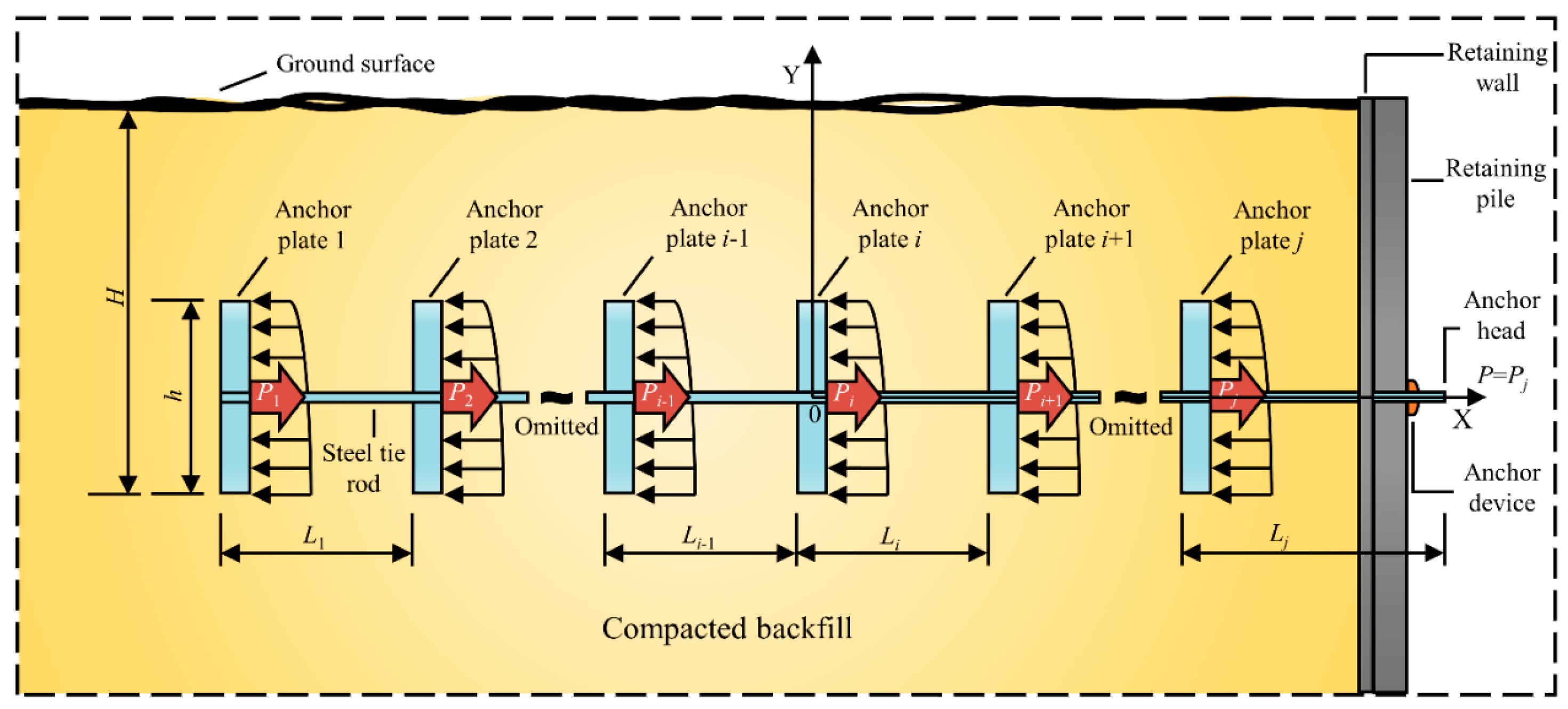
The series-connected anchor plates consist of j anchor plates and tie rod (as shown in Figure 1). Assume that the spacing between the adjacent anchor plates is sufficiently large (i.e., the mutual influence between adjacent anchor plates is not considered).
(3)
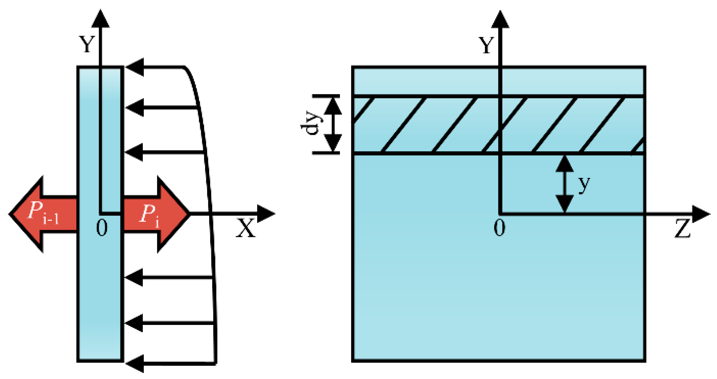
After the application of tension force, the anchor plate undergoes displacement, causing compression of the soil in front of the anchor plate. The soil in front of the anchor plate exerts horizontal resistance on the anchor plate, known as the elastic resistance of the soil. According to the Winkler assumption, the magnitude of elastic resistance σ is proportional to the displacement of the anchor plate, as shown in Equation (1):
σ = k x + y θ
where k represents the coefficient of the horizontal subgrade reaction of the soil in front of the anchor plate (kN/m3); x represents the horizontal displacement of the anchor plate (m); y is the distance of the calculation point from the x-axis (as shown in Figure 2), (m); θ represents the rotation angle of the anchor plate around its center (rad).
The soil horizontal subgrade reaction coefficient k is typically depth-dependent. Based on different assumptions regarding the variation in the coefficient k with depth, previous studies have proposed the M method (i.e., assuming k = my), the C method (i.e., assuming k = my0.5), and the K method (i.e., assuming k = constant) for the analysis of lateral load-bearing and the deformation characteristics of loaded piles. This paper assumed that the relationship between the horizontal subgrade reaction coefficient of the soil in front of the anchor plate varied with depth, as shown in Equation (2). The method derived based on this assumption for calculating the approximate analytical solution of the pull-out resistance–displacement relationship of the anchor plate is referred to as the T method in the subsequent text.
k = my h t
where m is the scaling factor of the subgrade reaction coefficient of the soil in front of the anchor plate (kN/m4); yh represents the depth of the calculation point (m); t is the depth-fitting parameter.
(4)
The anchor plate support system is generally used in fill projects. The scaling factor m of the subgrade reaction coefficient is influenced by various factors including the type of backfill material, compaction degree, and others. In engineering practice, determining this factor m, especially for compacted fill soils, is challenging. However, determining the cohesion and internal friction angle of compacted fill soil is comparatively simpler than determining the factor m. To achieve this, the study referenced the empirical equation for the parameter m, which is related to the soil’s cohesion and internal friction angle. This equation is recommended in the Chinese industry standard, Technical Specification for Retaining and Protection of Building Foundation Excavation (2012) [22]. Additionally, considering the influence of the anchor plate’s horizontal displacement on the parameter m, this paper proposed the following relationship between m and the horizontal displacement of the anchor plate:
m = k 1 0.2 φ 2 φ + c x n
Here, x denotes the horizontal displacement of the anchor plate (m); φ represents the internal friction angle of the soil (°); c is the cohesion of the soil (kPa); k1, n are regression parameters.

2.2. The Formula for Pull-Out Resistance–Displacement Relationship

The anchor plate, under the action of tensile force P, will experience both translation and rotation. Taking the i th anchor plate as the research object and using the center of the anchor plate as the coordinate origin, we established a Cartesian coordinate system, as shown in Figure 2, assuming that the horizontal displacement of the i th anchor plate is xi (m) and the rotation angle is θi (rad). On the anchor plate, consider a differential area dA, as shown in the shaded region in Figure 2. The resistance exerted by the soil on the differential area dA is σibdy, where b is the width of the rectangular anchor plate (m). Based on Equations (1) and (2), the resistance generated by soil in front of the plate on the unit area of the ith anchor plate is [23]:
σ i = m H h / 2 y t x i + y θ i
By the equilibrium conditions ∑Fx = 0 and ∑Mz = 0, the equilibrium equation of the anchor plate can be obtained as:
P i P i 1 h / 2 h / 2 σ i b d y = 0 h / 2 h / 2 σ i b d y = 0 i = 2 , 3 , j
where h represents the height of the rectangular anchor plate (m).
By combining Equation (3), Equation (4), and Equation (5), the pull-out resistance–displacement relationship of the ith anchor plate can be obtained as Equation (6):
P i P i 1 = k 1 k 2 k 3 x i n + 1 i = 1 , 2 , 3 , j
where when i = 1, Pi−1 = 0; k2 and k3 are shown in Equation (7) and Equation (8), respectively.
k 2 = 0.2 φ 2 φ + c
k 3 = b H h 4 + 2 t + h 3 t + 2 2 H t + 1 h 2 t 2 + 4 t + 6 H t + 2 + 4 H t + 3 h 2 H t + 4 H h t + H 4 + 2 t 2 t + 2 H h t 2 + t + 2 8 h 2 + H t 1 h 2 + H 2 H h t h 3 t + 3 t + 2 H t + 1 + 4 h t + 3 H t + 2 8 H t + 3

2.3. Applied to Series-Connected Anchor Plates

Based on Hooke’s law for axial tension and compression, and considering the displacement compatibility conditions between adjacent anchor plates, the relationship between the displacement of the i th and the (i − 1) th anchor plate can be formulated as:
x i = x i 1 + P i 1 L i 1 E S i = 2 , 3 , j
where Li−1 is the spacing between the (i − 1) th and i th anchor plates (m); E is the elastic modulus (MPa); S is the cross-sectional area of the tie rod (m2).
Substituting Equation (9) into Equation (6), the recursive formula for the axial tensile force in the series-connected rectangular anchor plate is obtained:
P i = k 1 k 2 k 3 x i 1 + P i 1 L i 1 E S n + 1 + P i 1 i = 2 , 3 , j
By applying Hooke’s law for axial tension and compression, the displacement calculation equation at the anchor head within the series-connected anchor plate support system is derived as follows:
x = x j + P j L j E S
where xj is the displacement of the last anchor plate (m); Pj is the tension force acting on the last section of the tie rod (kN); Lj is the distance from the last anchor plate to the anchor head (m).

3. Model Test and Numerical Simulation of Anchor Plate

3.1. Comparison of Numerical Simulation and Theoretical Analysis Results

In order to increase the number of fitting samples and verify the accuracy of the numerical simulation model, the research team conducted a large-scale model test.
It is well-known that when an anchor plate is subjected to tension, the soil on the side opposite to the direction of motion is in an unloading rebound state. The soil on this side will initially move with the displacement of the anchor plate and gradually detach. When the anchor plate is buried in poorly permeable clay, a certain suction is formed due to the super static pore pressure difference on the two sides of the anchor plate’s contact surface with the soil. This increases the pull-out bearing capacity of the anchor plate, known as the ‘suction’ effect, during the pull-out process. Rowe et al. (1978, 1982) [24,25] simplified the ‘soil-anchor’ contact characteristics into ‘immediate detachment’ and ‘no detachment’ conditions when addressing the suction effect. Due to the challenges in determining the magnitude of the suction effects in practical engineering, the influence of suction is typically neglected, and the ‘immediate detachment’ condition is adopted.
To eliminate the suction effect on the side of the anchor plate, the trapdoor model approach proposed by Gunn (1980) [26] was adopted for the model test conducted in this study. This involved creating an opening at the side of the model box to represent the location of the anchor plate. Subsequently, a pushing force was applied to the central position of the anchor plate on the side opposite to the direction of movement to simulate the pull-out load of the anchor plate. The thrust was applied horizontally by a 200 kN energy level booster through the opening at the side of the model box. The displacement of the anchor plate was measured by two displacement sensors set at the top and bottom of the plate. The data acquisition of the horizontal thrust and displacement was conducted automatically by the experimental system. The schematic diagram of the model test is shown in Figure 3.
The model test was conducted in a large outdoor model box with dimensions of 5.0 m × 5.0 m × 3.0 m. Two square anchor plates, labeled as #1 and #2, made of C30 reinforced concrete, were vertically buried on both sides of the model box, as shown in Table 1. The model box was filled with silty clay, which was compacted in layers with a thickness of 15 cm and a compaction degree of 93% to ensure the quality of soil compaction. After the completion of the model test and a 30-day static placement, samples were taken for geotechnical testing. The measured geotechnical parameters of the compacted filling materials are shown in Table 2.
Even though the elastic modulus of soil is needed in the numerical simulation, there is no uniform standard for the indoor testing of the elastic modulus of soil. This study drew on the Chinese industry Specification, Specifications for Design of Highway Asphalt Pavement (2017) [27], and employed the lateral method to determine the elastic modulus of soil through single-axis compression. The methodology was as follows:
The axial deformation of the specimen was measured by the sensor from its side, and the strain was calculated by averaging the deformations measured by three displacement sensors. Load–strain curves were recorded, the elastic modulus was calculated using Equation (12).
E = 1.2 F π d 2 ε
where F is the large load (N); d is the diameter of the specimen (mm); the longitudinal strain of the specimen, denoted as ε, is measured when the applied loading reaches 0.3 F; ε = Δl/l, Δl is the axial deformation of the specimen (mm); l is the height of the specimen (mm) [28].

3.2. Establishment of Three-Dimensional Simulation Model

For a comprehensive and systematic investigation of the pull-out bearing characteristics and influencing factors of the anchor plate, a finite difference model of the interaction between the anchor plate and the soil was established using the FLAC3D.6.0 software. Constitutive relationship and element division: The soil as modeled using the elastic-plastic Mohr-Coulomb constitutive model. Uniform cubic elements with dimensions of 0.1 × 0.1 × 0.1 m were employed for the soil elements. The anchor plate and tie rod were simulated by structural elements according to their actual sizes. The anchor plate was modeled using Shell element and assumed to be perfectly rigid. The tie rod was represented by the Cable element, and the frictional resistance between the tie rod and the surrounding soil was neglected. Loading and boundary conditions: The load was applied directly and horizontally to the node at the end of the tie rod. The gravity acceleration field was maintained throughout the analysis to consider the effect of soil weight on the pull-out bearing and deformation properties of the anchor plate. The boundary conditions of the model are as shown in Figure 4: the velocities in the X, Y, and Z directions on the east, west, south, north, and bottom faces were constrained, while the model’s top face was set as a free surface without constraints.
The theoretical analysis also found that when the normal force on the AE and DF interfaces, where the lateral soil-cement wall was in contact with the soil, was taken as the passive earth pressure, and the passive earth pressure reduction coefficient was set to 1.0, the maximum settlement at the center of the embankment load was obtained as 221.3 mm, which was close to the numerical simulation result of 261.6 mm without the lateral soil-cement wall. From the numerical simulation results, it is known that for soft soil foundations with soil-cement lateral restriction, when the lateral restriction can completely limit the horizontal displacement of soil within the load-bearing range, the settlement at the center point of the load is reduced by nearly 40% compared with the situation without lateral restriction.

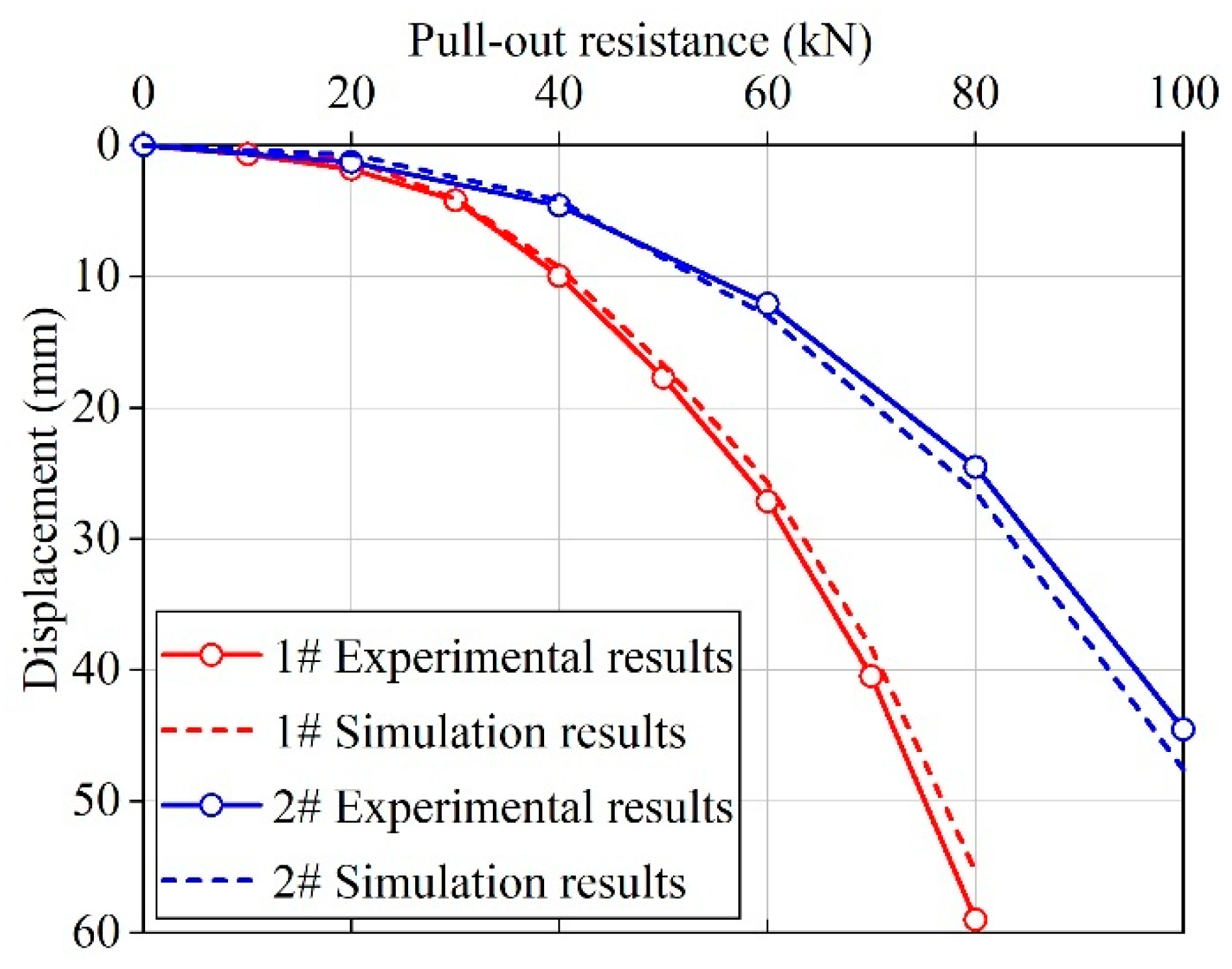
3.3. Comparison of Results

To obtain a correct and effective finite difference model for the interaction between the anchor plate and soil, a numerical simulation was conducted to mimic the model experiment. The results of the simulation were then compared with the experimental results to verify the rationality of the numerical simulation model.
The relevant parameters are shown in Table 1 and Table 2. The Poisson’s ratio v of the soil was taken as 0.3; the average elastic modulus of the soil measured from nine specimens in the chamber was 14.3 MPa. The bulk modulus K and shear modulus G of the soil can be obtained from Equations (13) and (14).
K = E 3 1 2 v
G = E 2 1 + v
As illustrated in Figure 5, the numerical simulation results exhibited a high degree of consistency with the experimental findings, which effectively corroborated the rationality of the numerical simulation model developed in this study.

4. Parameters Fitting

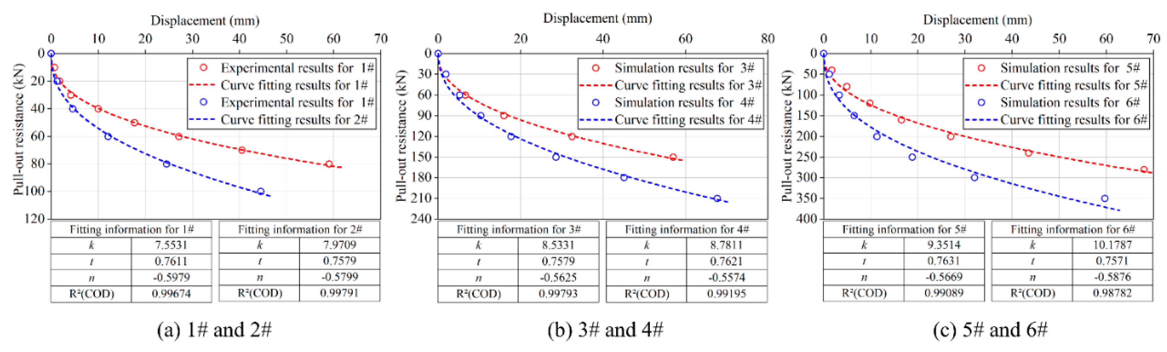
4.1. The Determination of Fitting Samples

Using Equation (6) as the fitting function, if only the results of the model test are utilized, insufficient fitting samples will lead to an inaccurate reflection of the influence of the anchor plate size and burial depth on the parameters k1, t, and n to increase the number of samples and ensure the reasonableness and reliability of the fitting results of the three parameters. By using the validated FLAC3D simulation model, additional numerical simulation results for the pull-out resistance-horizontal displacement of #3–#12 anchor plates were obtained.

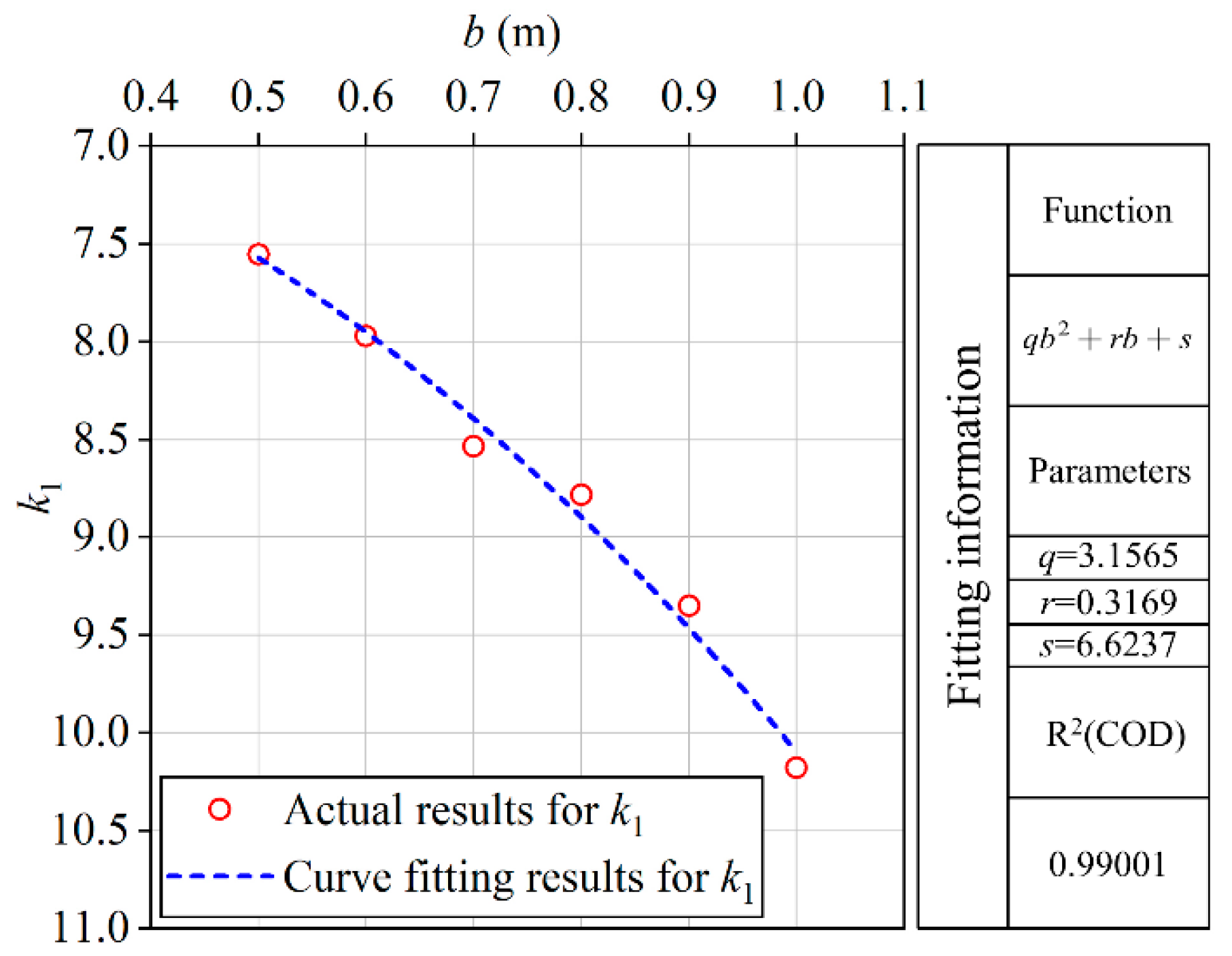
4.2. Fitting of Regression Parameters k1, t, and n for Anchor Plates with Different Sizes

The burial depth of the #3–#6 square anchor plates remained unchanged. The side lengths of these anchor plates were incremented by 0.1 m sequentially, with the dimensions of the #2 anchor plate in Table 1 serving as the baseline. Through the fitting analysis, the comparison curves for the #1–#6 anchor plates of the experimental model and numerical simulation results with the fitting results were obtained, as shown in Figure 6. As seen in the figure, the goodness-of-fit (R2) was consistently around 0.99. This suggests a close alignment between the fitting results and both the experimental and simulation results. Meanwhile, the three regression parameters k1, t, and n in Equation (6) were obtained as shown in Table 3. From Table 3, it can be seen that the regression parameters t and n were quite close to each other for the different sizes of anchor plates, but parameter k1 was significantly different. This indicates that the size of the anchor plate had a very small influence on the regression parameters t and n, while it had a significant impact on the k1. The average approximate values of the t and n can be taken as the calculated values for theoretical analysis.
After analyzing the curve relationship between the regression parameters k1 and b, it was found that the relationship between these two parameters for square anchor plates closely resembled a quadratic function. Therefore, it was hypothesized that the fitting relationship between k1 and b for the square anchor plates can be given by:
k 1 = q b 2 + r b + s
where q, r, and s are undetermined parameters.
Using Equation (15) as the fitting function, the regression parameter k1 for #1–#6 anchor plates in Table 3 was fitted, and the fitting curve is shown in Figure 7. As seen from Figure 7, the R2 was 0.99, indicating an excellent fitting effect. The undetermined parameters were q = 3.1565, r = 0.3169, and s = 6.6237.

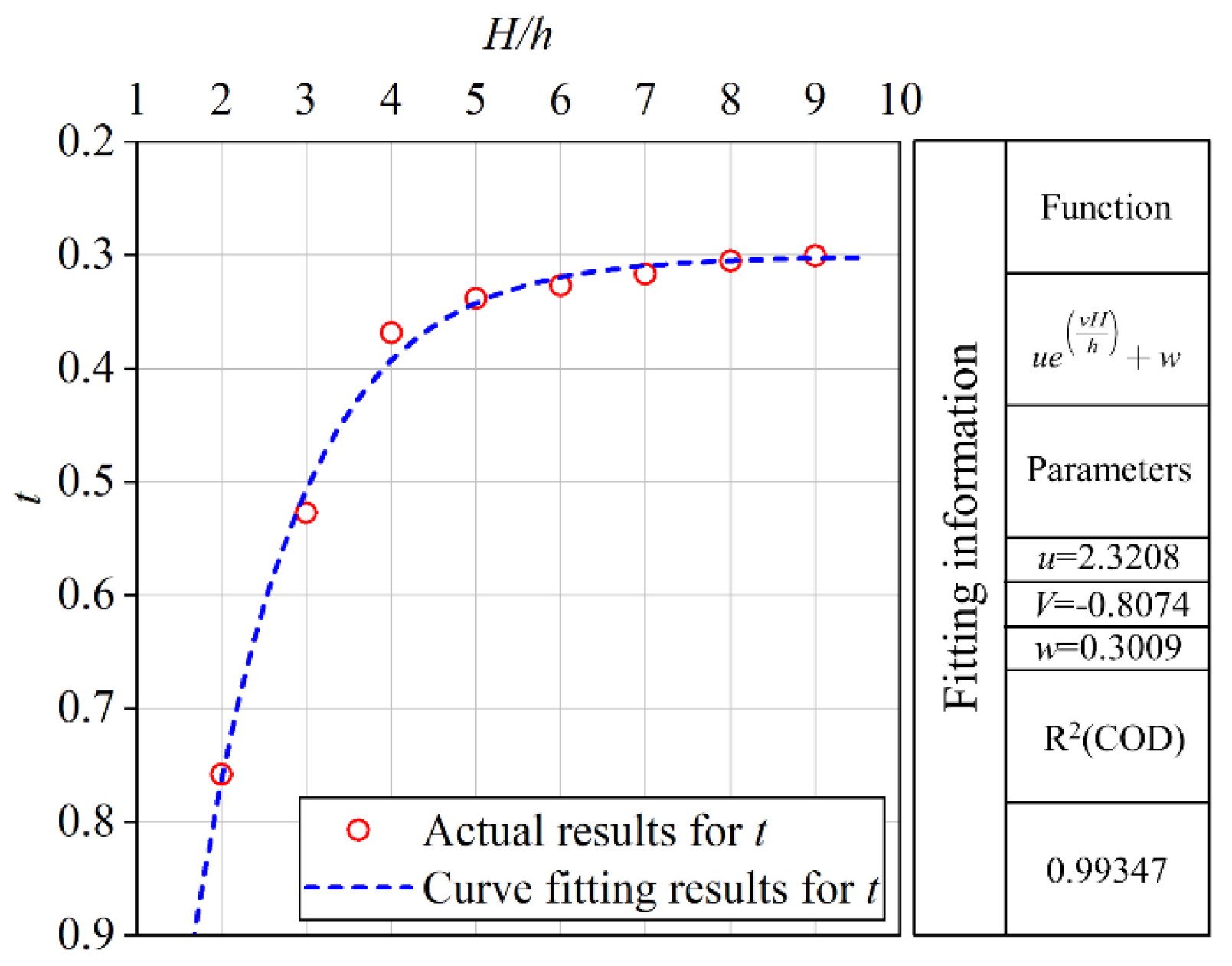
4.3. Fitting of Regression Parameters t and n for Anchor Plates with Different Burial Depths

To obtain the parameters t and n for anchor plates with different burial depths, Equation (6) was adopted as the fitting function, with k1 determined using Equation (15). The numerical simulation results for the #6–#13 anchor plates were fitted separately. The side length of the #6–#13 square anchor plates was uniformly 1.0 m. The burial depths of the #7–#13 anchor plates were incremented by b sequentially, with the burial depth of the #6 anchor plate serving as the baseline. In the same way as Figure 6, the parameters t and n of the #6–#13 anchor plates are shown in Table 4, with the R2 value consistently maintaining a level around 0.99. When the depth ratios of anchor plates burying H/h were around 8 and 9, the t showed little variation with changes in the anchor plate’s burial depth. Applying the theoretical analysis method developed in this paper to analyze the pull-out resistance–displacement relationship of the anchor plates under the condition of burial depth ratio H/h > 9, satisfactory results were obtained by setting t = 0.3. The average approximate values of the n can be taken as the calculated values for theoretical analysis.
Through the analysis, it was found that the relationship between the t and H/h approximated an inverse proportion function. Therefore, it was assumed that the fitting relationship between the t and H/h can be given by:
t = u e V H h + w
where u, V, and w are undetermined parameters.
Using Equation (16) as the fitting function, the regression parameter t for the #6–#13 anchor plates in Table 4 was fitted, and the fitting curve is shown in Figure 8. As seen from Figure 8, the R2 was 0.99. The undetermined parameters were u = 2.3208, V = −0.8074, and w = 0.3009.

5. M Method and C Method

Building upon the assumption that the foundation coefficient k increases linearly or parabolically with depth, previous researchers introduced the M and C methods to analyze the lateral load-bearing and deformation characteristics of loaded piles. By setting t equal to 1.0 and 0.5 in Equation (8), this study derived the calculations in Equations (17) and (18) for the coefficient k3 in the M and C methods, respectively. Combining Equation (6) and Equation (7), the pull-out resistance–displacement relationship of the ith anchor plate can be determined. The analysis method for the pull-out resistance–displacement relationship of the anchor plates presented in this paper, based on t values of 1.0 and 0.5, is also referred to as the M and C methods.
k 3 = b h 6 H 2 6 H h + h 2 6 H 3 h
k 3 = 64 b 25 H 3 2 h 3 8 33 H 5 2 h 2 8 + 2 H 7 2 h H 9 2 H h + H h 2 H 4 2 H 3 h + 4 H 2 h 2 3 H 3 h + h 4 160 H 3 200 H 2 h + 95 H h 2 55 h 3 H h 175 H 3 2 h 2 + 280 H 5 2 h 160 H 7 2
In order to determine k1 and n in the M and C methods, Equation (6) was employed as the fitting function. The fitting results are detailed in Table 5 and Table 6 and the R2 values were all around 0.99. As can be seen from the tables, there was a significant variation in k1; the average approximate values of the n can be taken as the calculated values for theoretical analysis.
To establish the relationship between the k1 and b, Equation (15) was employed as the fitting function. The undetermined parameters for the M method were q = 5.3696, r = −2.3335, and s = 6.4571, while the undetermined parameters for the C method were q = 2.8196, r = 0.5074, and s = 7.7747.

6. Examples and Verifications

To verify the reliability of the theoretical analysis and numerical simulation, the on-site experimental results of three engineering cases were compared with those of the theoretical analysis and numerical simulation. Since prestress was applied to the tie rods in the engineering cases, the actual displacement of the anchor plates was calculated by deducting the elastic deformation of the tie rods.
The elevation view of the anchor plate anchored retaining wall system in engineering case 1 and case 2 is depicted in Figure 9. From Figure 9, it is evident that the support system primarily comprised retaining piles, retaining walls, tie rods, anchor plates, and anchor devices as well as compacted backfill surrounding the anchor plates.

6.1. Engineering Case 1

The height of the slope support was 8.5 m, and the single anchor plate anchored retaining wall system was employed for support. The cross-sectional diagram of the system is illustrated in Figure 10. The retaining piles were spaced 3.5 m apart, with each pile featuring a square section of 1.0 m × 1.0 m and constructed from C30 reinforced concrete. The retaining walls were comprised of C30 reinforced concrete, with a thickness of 0.20 m. The system was buried with square anchor plates located at a depth of 4.5 m, each measuring 1.0 m × 1.0 m. The anchor plates were constructed from C30 reinforced concrete, with a thickness of 0.25 m and were spaced horizontally at intervals of 3.5 m. The tie rods were made of 3Φs15.2 steel strand, with E of 1.95 × 10⁵ MPa and a length of 15.0 m. The backfill behind the wall consisted of compacted silty clay in layers. Following layered compaction of the backfill, indoor tests were conducted based on field samples, which determined the soil’s E to be 15.8 MPa. The other geotechnical parameters are as shown in Table 7, with a Poisson’s ratio of 0.3.
As shown in Figure 11, the results obtained by the T method aligned well with the on-site experimental results.

6.2. Engineering Case 2

The height of the slope support in the Huaxiangli Leisure Resort area was 12.5 m, and a series-connected anchor plates anchored retaining wall system was employed for support. The cross-sectional diagram of the system is illustrated in Figure 12. The retaining piles were spaced 3.5 m apart, with each pile featuring a rectangular section of 1.0 m × 1.2 m and constructed from C30 reinforced concrete. The retaining walls were comprised of C30 reinforced concrete, with a thickness of 0.20 m. The series-connected double anchor plates, each measuring 1.0 m × 1.0 m, were buried at depths of 4.5 m, 7.5 m, and 10.5 m, respectively, with a spacing of 5.0 m between adjacent plates. The anchor plates were constructed from C30 reinforced concrete, with a thickness of 0.25 m, and were spaced horizontally at intervals of 3.5 m. The tie rods were made of 4Φs15.2 steel strands, with E of 1.95 × 10⁵ MPa. The lengths of the tie rods for the first, second, and third rows of the anchor plates were 20.0 m, 15.0 m, and 13.0 m, respectively. The backfill behind the wall consisted of compacted silty clay in layers, with an E value of 16.2 MPa. The other geotechnical parameters are as shown in Table 8, with a Poisson’s ratio of 0.3.
As shown in Figure 13, the results obtained by the T method under any burial depth conditions were in good agreement with the on-site experimental results.

6.3. Engineering Case 3

The data for this case were sourced from Zhang et al. (1996) [29], which involved two square reinforced concrete anchor plates vertically buried in compacted silty clay. The anchor plates had dimensions of 1.0 m × 1.0 m and 1.4 m × 1.4 m, and both were buried at a depth of 4.9 m. The tie rods were all 3Φ25 threaded steel bars, with a length of 14 m, and an E of 2.0 × 10⁵ MPa. The tensioning equipment used for the pull-out experiment of the anchor plates as a 600 kN hydraulic jack. The compacted silty clay had a φ of 22.36°, c of 27 kPa, and γ of 19.8 kN/m3. As observed in Figure 14, the numerical simulation results, theoretical analysis results using the T method, and on-site experimental results were in good agreement.
The comparison of multiple pull-out resistance–displacement relationship curves in the three engineering cases revealed that the calculated pull-out bearing capacity using the M method and C method was excessively high. In contrast, the results obtained using the proposed T method in this paper were in good alignment with the on-site experimental results.

7. Factors Influencing the Pull-Out Bearing Capacity

7.1. The Minimum Spacing Between Adjacent Anchor Plates

It is well-known that anchor plates are installed on retaining piles or other structures with a certain spacing, forming a group that jointly provides the necessary pull-out resistance for the support system. However, in traditional single anchor plate support systems, anchor plates are often densely arranged on the same plane, leading to mutual interference among them, and thereby reducing the overall pull-out capacity. To address this issue, scholars have focused on the impact of plate spacing and other factors on the behavior of the group of anchor plates (Mokhbi, et al. (2018) [30]; Choudhary et al. (2019) [31]).
The series-connected anchor plate system, which offers higher pull-out capacity, reduces the number of anchor plate rows, thereby increasing the horizontal and vertical spacing between anchor plates. However, for the series-connected anchor plate system itself, the minimum spacing required to prevent interference between the front and rear anchor plates remains a subject for further discussion.
Taking the series-connected double anchor plates as an example, simulations and calculations were conducted utilizing the parameters from engineering case 2 to explore the impact of the spacing between anchor plates on the pull-out bearing characteristics of series-connected anchor plates. Given that the fundamental assumption (2) stated earlier posits that the interaction between adjacent anchor plates will be disregarded in the theoretical analysis, solely numerical simulations will be performed in this instance, and the results derived from the T method will serve as a mere reference.
Figure 15 presents the numerical simulation results of the influence of variations in the spacing between the front and rear anchor plates on the pull-out resistance–displacement relationship of series-connected square anchor plates, with a burial depth of 8b (b = 1.0 m, representing the side length of the square anchor plate).
As observed in Figure 15, the pull-out bearing capacity of the anchor plates increased significantly with increasing plate spacing when the spacing L was less than 4b. However, for plate spacings L greater than or equal to 4b, the increase in pull-out bearing capacity became relatively small with further increments in the spacing of the anchor plates.
Figure 16 shows the displacement contour–vector diagram of the soil around series-connected anchor plates. As can be observed from the figure, when the anchor plate spacing was L < 4b, the soil displacement caused by the front anchor plate had a significant impact on the rear anchor plate. Its shape can be considered as a column, and notably, with the gradual increase in the spacing L, the failure surface near the middle gradually concaved inward, suggesting a change in the stress distribution and transmission within the soil. On the other hand, when the anchor plate spacing was L ≥ 4b, the impact of soil displacement caused by the front anchor plate on the rear anchor plate was relatively small. The soil displacement fields between the two plates were relatively independent, and the failure surfaces were largely separated.
To summarize, to avoid the influence of adjacent anchor plates on the pull-out bearing capacity in the series-connected anchor plate support system, the minimum spacing between adjacent anchor plates should be L = 4b. In other words, when the spacing between adjacent anchor plates L ≥ 4b, each anchor plate can better independently exert its own pull-out bearing capacity without mutual interference.

7.2. The Influence of Soil Strength Parameters on the Minimum Spacing of Anchor Plates

Figure 17 displays the displacement contour–vector diagram of soil surrounding the series-connected square anchor plates with a burial depth of 8b and a spacing of 4b between plates. Specifically, Figure 17a,b depicts the soil conditions with a cohesion of c = 30 kPa and internal friction angles of φ = 15° and φ = 35°, respectively. Meanwhile, Figure 17c,d represents the soil conditions with an internal friction angle of φ = 20° and cohesions of c = 25 kPa and c = 45 kPa, respectively.
The above numerical simulation results indicate that for normal cohesive soils with internal friction angles ranging from 15° to 35° and cohesions varying between 25 kPa and 45 kPa, the geotechnical strength parameters had a minor influence on determining the minimum spacing required for series-connected anchor plates.

7.3. The Critical Depth Between Deeply Buried and Shallowly Buried Anchor Plates

Some scholars believe that there is a critical depth between deeply buried and shallowly buried anchor plates. Dickin et al. (1985) [32] reported that the failure surface of shallowly buried anchor plates generally extends to the soil surface, but at greater depths, the failure surface tends to be local and rotational, with the bearing capacity remaining almost unchanged.
This study took the traditional single anchor plate as an example to explore the size of the critical depth of the anchor plate. A numerical simulation and theoretical calculations were performed using the parameters from engineering case 1. Figure 18a,b presents the theoretical calculation results and numerical simulation results of the pull-out resistance–displacement relationship, influenced by varying burial depths of the anchor plate. As can be observed from the figure, when H < 4b, the pull-out bearing capacity of the anchor plate increased significantly with an increase in burial depth, and this increase was substantial. However, when H ≥ 4b, the increase in pull-out bearing capacity became relatively minor with further increases in burial depth.
Figure 19 illustrates the displacement contour–vector diagram of soil around the anchor plates at various burial depths. From Figure 19, it can be observed that when the burial depth of the anchor plate H < 4b, the tension applied to the plate resulted in its forward movement, causing surface upheaval and substantial disturbance to the soil above the anchor plate. Conversely, when the burial depth was H ≥ 4b, the forward movement of the anchor plate hardly induced surface upheaval, and the failure surface tended to become increasingly localized. This figure is similar to the findings presented by Merifield et al. (2001) [11].
In summary, when the burial depth of the anchor plate was H < 4b, the pull-out bearing capacity of the anchor plate was closely related to the burial depth, exhibiting the characteristic failure mode of shallowly buried anchor plates. Conversely, when the burial depth was H ≥ 4b, the impact of burial depth on the pull-out bearing capacity became less significant, and the failure mode assumed the characteristic of deeply buried anchor plates.

7.4. The Influence of Soil Strength Parameters on the Critical Depth of Anchor Plate

Figure 20 displays the displacement contour–vector diagram of the soil surrounding the square anchor plate with a burial depth of 4b. Specifically, Figure 20a,b depicts the soil conditions with a cohesion of c = 30 kPa and internal friction angles of φ = 15° and φ = 35°, respectively. Meanwhile, Figure 20c,d represents the soil conditions with an internal friction angle of φ = 20° and cohesions of c = 25 kPa and c = 45 kPa, respectively.
The above numerical simulation results indicate that for normal cohesive soils with internal friction angles ranging from 15° to 35° and cohesions varying between 25 kPa and 45 kPa, the geotechnical strength parameters had a minor influence on determining the critical depth between the deeply buried and shallowly buried anchor plates.

8. Conclusions

(1)
To enhance the pull-out bearing capacity of the anchor plate support system, a series-connected anchor plate support system was proposed. A theoretical analysis method for the pull-out resistance–displacement relationship of series-connected anchor plates was established. Utilizing the findings from large-scale model experiments, along with numerical simulation results and via fitting analysis, approximate analytical solutions for the pull-out resistance–displacement relationship of series-connected anchor plates were obtained. This lays the theoretical foundation for achieving the dual control of both displacement and pull-out resistance in the design of the anchor plate support system.
(2)
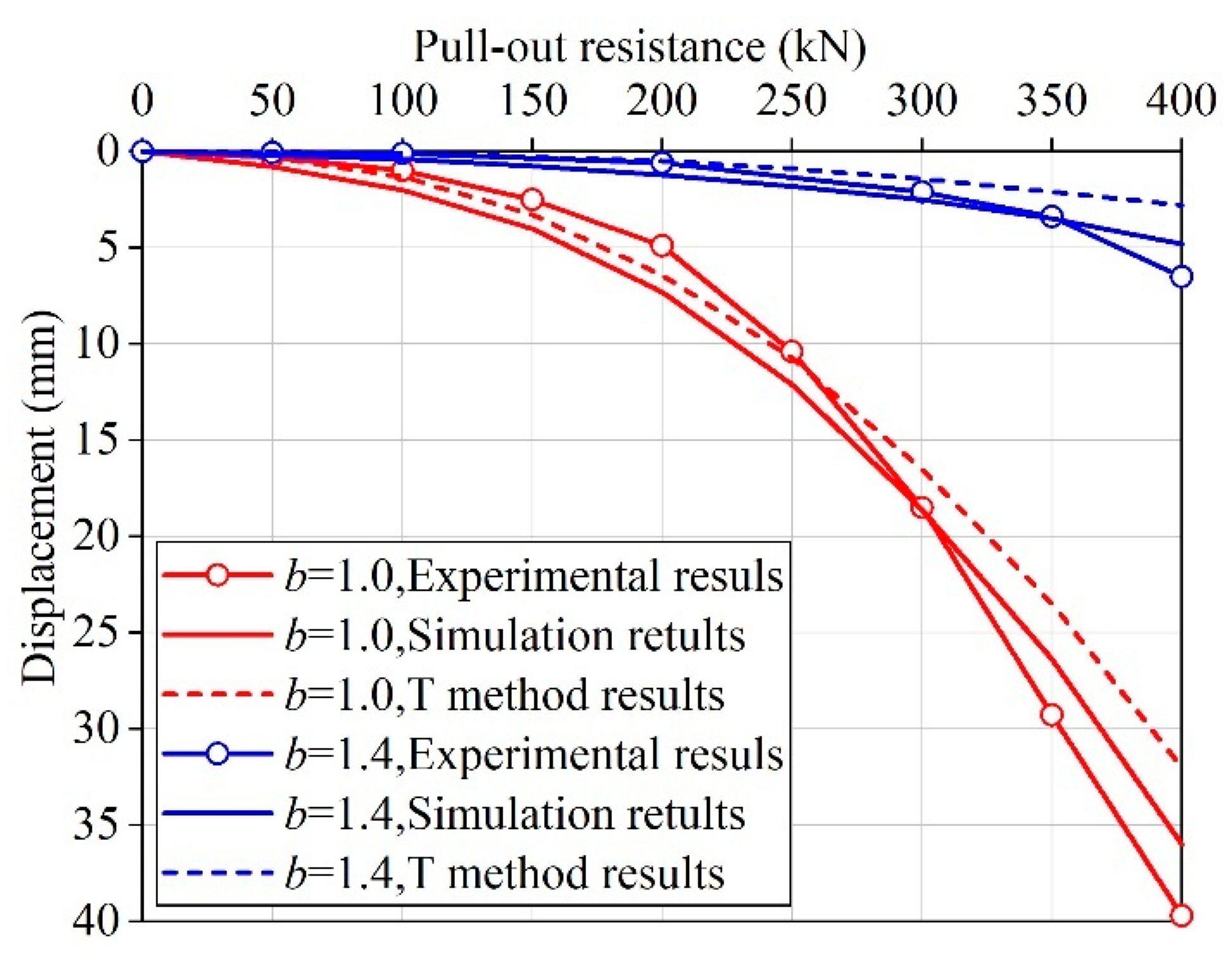
Through the analysis of various engineering cases, it was conclusively demonstrated that the proposed T method for analyzing the pull-out resistance–displacement relationship of anchor plates is not only effective, but also feasible. Furthermore, it exhibits remarkable accuracy and rationality, thus providing valuable insights for engineering practice.
(3)
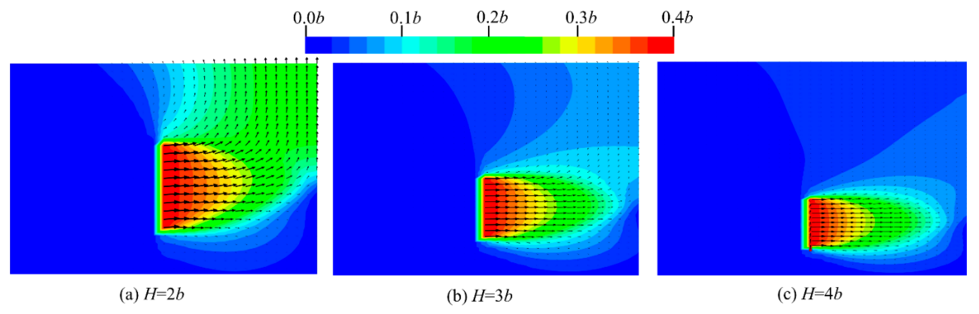
For vertically shallow-buried anchor plates, their pull-out bearing capacity increased notably as the burial depth increased. Pulling out the anchor plate can cause surface upheaval, and the failure mode exhibited the characteristics typical of shallow-buried anchor plates. On the contrary, for vertically deep-buried anchor plates, their pull-out bearing capacity increased only slightly with the increase in burial depth. The critical depth between deeply buried and shallowly buried anchor plates was approximately 4b (where b represents the side length of the square anchor plate).
(4)
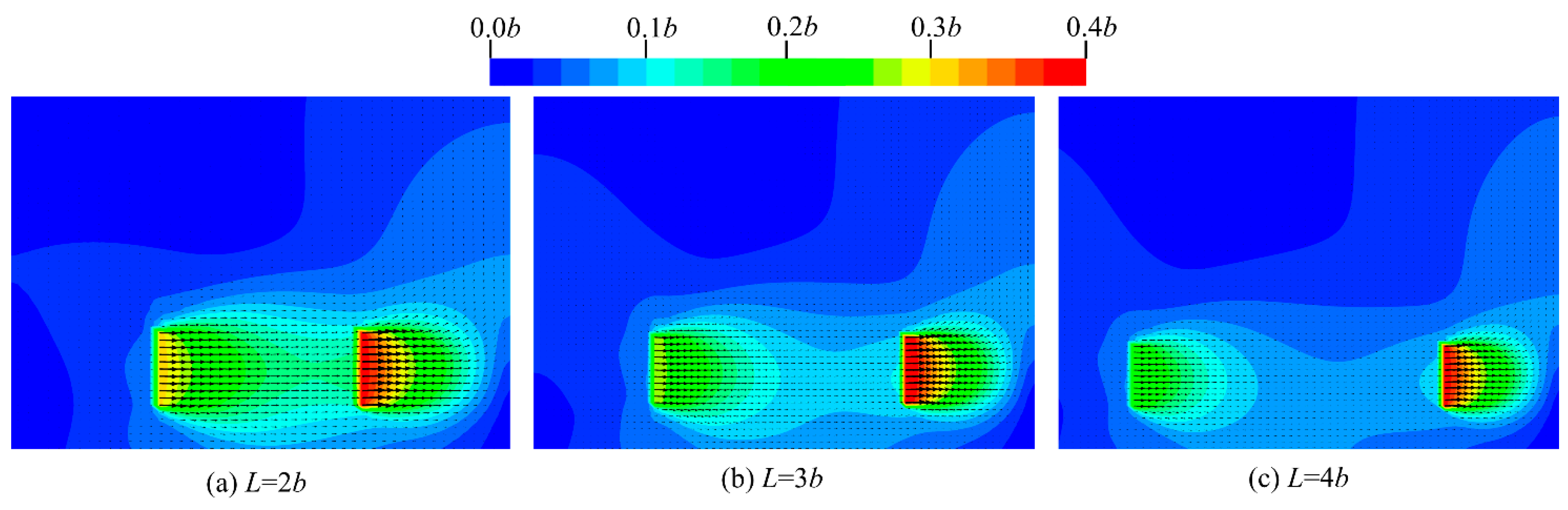
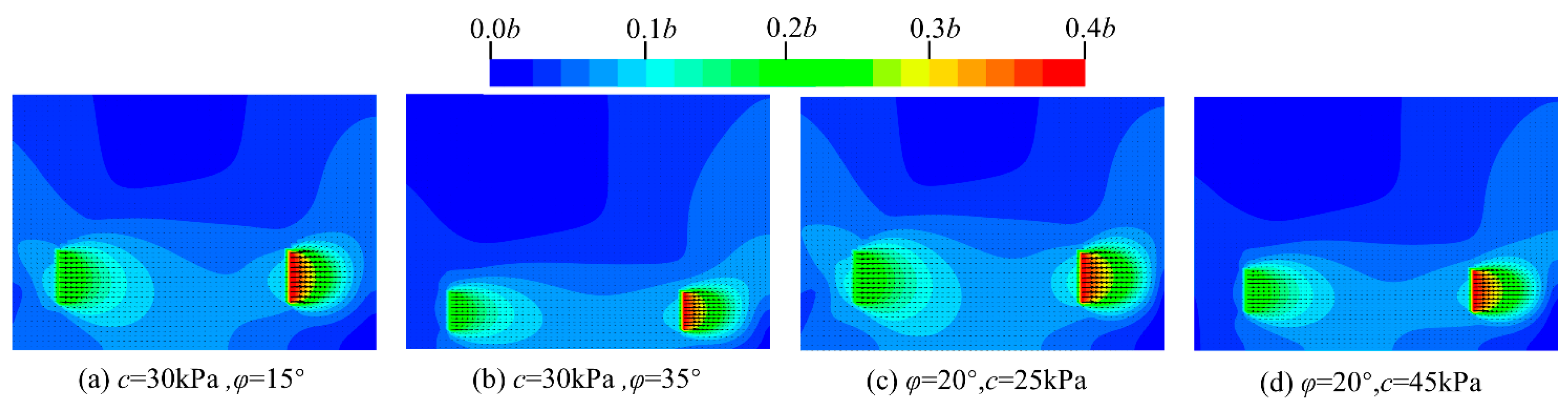
For the series-connected anchor plates, in order to avoid mutual interference between adjacent anchor plates and reduce the pull-out bearing capacity of the support system, the minimum spacing between adjacent anchor plates should satisfy L ≥ 4b. For typical cohesive soils, the magnitude of cohesion and the internal friction angle have little influence on the critical depth between deeply buried and shallowly buried anchor plates as well as on the minimum spacing between adjacent anchor plates.

Author Contributions

Conceptualization, C.N. and J.L.; Methodology, C.N.; Software, C.N.; Validation, C.N. and X.T.; Formal analysis, C.N.; Investigation, C.N. and J.L.; Resources, J.L.; Data curation, J.L.; Writing—original draft preparation, J.L., C.N. and X.T.; Writing—review and editing, J.L., C.N., X.Z. and X.T.; Visualization, J.L.; Supervision, J.L.; Project administration, J.L.; Funding acquisition, J.L. All authors have read and agreed to the published version of the manuscript.

Funding

The research presented here was supported by the National Natural Science Foundation of China (51978260). This support is gratefully acknowledged by the authors.

Data Availability Statement

The data presented in this study are available on request from the corresponding author.

Acknowledgments

We are grateful to the anonymous reviewers for their constructive comments.

Conflicts of Interest

The authors declare no conflicts of interest.

Notation

kCoefficient of horizontal subgrade reaction
σThe elastic resistance of the soil
xHorizontal displacement of the anchor plate
yThe distance of the calculation point from the x-axis
yhThe depth of the calculation point
θRotation angle
mScaling factor of the subgrade reaction coefficient
φInternal friction angle
cCohesion
k1Regression parameter
nRegression parameter
bThe width of the rectangular anchor plate
hThe height of the rectangular anchor plate
k2Equals to 0.2φ2-φ + c
k3Regression parameter
LTie rod length
EElastic modulus
SCross-sectional area of the steel tie rod
FThe large load
DDiameter of the specimen
ΕEquals to Δl/l
KBulk modulus
GShear modulus
VPoisson’s ratio

References

  1. Randolph, M.; Gourven1ec, S. Offshore Geotechnical Engineering; CRC Press: Boca Raton, FL, USA, 2017. [Google Scholar]
  2. Das, B.M.; Shukla, S.K. Earth Anchors; J. Ross Publishing: Plantation, FL, USA, 2013. [Google Scholar]
  3. Murray, E.J.; Geddes, J.D. Resistance of passive inclined anchors in cohesionless medium. Géotechnique 1989, 39, 417–431. [Google Scholar]
  4. Ilamparuthi, K.; Dickin, E.A.; Muthukrisnaiah, K. Experimental investigation of the uplift behaviour of circular plate anchors embedded in sand. Can. Geotech. J. 2002, 39, 648–664. [Google Scholar]
  5. Gaudin, C.; O’Loughlin, C.D.; Randolph, M.F.; Lowmass, A.C. Influence of the installation process on the performance of suction embedded plate anchors. Géotechnique 2006, 56, 381–391. [Google Scholar]
  6. Liu, J.; Liu, M.; Zhu, Z. Sand deformation around an uplift plate anchor. J. Geotech. Geoenviron. Eng. 2012, 138, 728–737. [Google Scholar]
  7. Han, C.; Wang, D.; Gaudin, C.; O’Loughlin, C.D.; Cassidy, M.J. Behaviour of vertically loaded plate anchors under sustained uplift. Géotechnique 2016, 66, 681–693. [Google Scholar]
  8. Basudhar, P.K.; Singh, D.N. Discussion: A generalized procedure for predicting optimal lower bound break-out factors of strip anchors. Géotechnique 1995, 45, 345–347. [Google Scholar]
  9. Khatri, V.N.; Kumar, J. Effect of anchor width on pullout capacity of strip anchors in sand. Can. Geotech. J. 2011, 48, 511–517. [Google Scholar]
  10. Kumar, J. Seismic horizontal pullout capacity of vertical anchors in sands. Can. Geotech. J. 2002, 39, 982–991. [Google Scholar]
  11. Merifield, R.S.; Sloan, S.W.; Yu, H.S. Stability of plate anchors in undrained clay. Géotechnique 2001, 51, 141–153. [Google Scholar]
  12. Merifield, R.S.; Lyamin, A.V.; Sloan, S.W.; Yu, H.S. Three-dimensional lower bound solutions for stability of plate anchors in clay. J. Geotech. Geoenviron. Eng. 2003, 129, 243–253. [Google Scholar]
  13. Merifield, R.S.; Lyamin, A.V.; Sloan, S.W. Stability of inclined strip anchors in purely cohesive soil. J. Geotech. Geoenviron. Eng. 2005, 131, 792–799. [Google Scholar]
  14. Bhattacharya, P.; Kumar, J. Pullout capacity of inclined plate anchors embedded in sand. Can. Geotech. J. 2014, 51, 1365–1370. [Google Scholar]
  15. Sahoo, J.P.; Ganesh, R. Vertical uplift resistance of rectangular plate anchors in two layered sand. Ocean. Eng. 2018, 150, 167–175. [Google Scholar]
  16. Xu, Z.D.; Wu, K.Y. Damage detection for space truss structures based on strain mode under ambient excitation. J. Eng. Mech. 2012, 138, 1215–1223. [Google Scholar]
  17. Xu, Z.D.; Wu, Z. Energy damage detection strategy based on acceleration responses for long-span bridge structures. J. Eng. Struct. 2007, 29, 609–617. [Google Scholar]
  18. Bu, G.; Chen, K.; Zhou, J.; Ma, X.; Xu, C.; Liu, F.; He, A. Seismic fragility assessment of eccentric gravity column-core tube structures subjected to pulse-like ground motions. Structures 2024, 69, 107406. [Google Scholar]
  19. Ghaly, A.M.; Hanna, A. Ultimate pullout resistance of single vertical anchors. Can. Geotech. J. 1994, 31, 661–672. [Google Scholar]
  20. White, D.J.; Take, W.A.; Bolton, M.D. The uplift resistance of pipes and plate anchors buried in sand. Géotechnique 2003, 58, 771–779. [Google Scholar]
  21. Tho, K.K.; Chen, Z.; Leung, C.F.; Chow, Y.K. Pullout behaviour of plate anchor in clay with linearly increasing strength. Can. Geotech. J. 2014, 51, 92–102. [Google Scholar]
  22. JGJ 120-2012; Technical Specification for Retaining and Protection of Building Foundation Excavation. China Architecture & Building Press: Beijing, China, 2012. (In Chinese)
  23. Liu, J.; Yang, Q.; Tan, X.; Ma, Y. Research on Analysis Method of Load-Displacement Relationship of Series Anchor Plates. J. For. Chem. Rev. 2021, 1536–1553. [Google Scholar]
  24. Rowe, R.K. Soil Structure Interaction Analysis and its Application to the Prediction of Anchor Plate Behaviour. Ph.D. Thesis, University of Sydney, Sydney, Australia, 1978. [Google Scholar]
  25. Rowe, R.K.; Davis, E.H. The behaviour of anchor plates in clay. Géotechnique 1982, 32, 9–23. [Google Scholar]
  26. Gunn, M.J. Limit analysis of undrained stability problems using a very small computer. In Symposium on Computer Applications in Geotechnical Problems in Highway Engineering; University Engineering Department: Cambridge, UK, 1980. [Google Scholar]
  27. JTG D50-2017; Specifications for Design of Highway Asphalt Pavement. China Communication Press: Beijing, China, 2017. (In Chinese)
  28. Liang, L.; Zou, X.; Liu, J. Approximate analytical algorithm for pull-out resistance-displacement relationship of combined anchor system. J. Eng. Fail. Anal. 2024, 166, 108827. [Google Scholar]
  29. Zhang, X.; Wu, X. Theory and Practice of Anchor Plate Retaining Structures; China Railway Publishing House: Beijing, China, 1996. [Google Scholar]
  30. Mokhbi, H.; Mellas, M.; Mabrouki, A.; Pereira, J.M. Three-dimensional numerical and analytical study of horizontal group of square anchor plates in sand. Acta Geotech. 2018, 13, 159–174. [Google Scholar]
  31. Choudhary, A.K.; Pandit, B.; Sivakumar Babu, G.L. Experimental and numerical study on square anchor plate groups in geogrid reinforced sand. Geosynth. Int. 2019, 26, 657–671. [Google Scholar]
  32. Dickin, E.A.; Leung, C.F. Evaluation of design methods for vertical anchor plates. J. Geotech. Eng. 1985, 111, 500–520. [Google Scholar]
Figure 1. Schematic diagram of the series-connected anchor plate support system.
Buildings 15 01177 g001
Figure 2. Force diagram of the rectangular anchor plate.
Buildings 15 01177 g002
Figure 3. Illustration of the model test.
Buildings 15 01177 g003
Figure 4. Illustration of three-dimensional simulation model.
Buildings 15 01177 g004
Figure 5. Comparison curve between the simulation results and model experimental results of the anchor plates.
Buildings 15 01177 g005
Figure 6. Comparison of the pull-out resistance-displacement result curves of the anchor plates with different sizes.
Buildings 15 01177 g006
Figure 7. Fitting results of the anchor plates with different sizes.
Buildings 15 01177 g007
Figure 8. Fitting results of the anchor plates with different burial depths.
Buildings 15 01177 g008
Figure 9. Schematic elevation of the anchor plate anchored retaining wall system.
Buildings 15 01177 g009
Figure 10. Cross-sectional diagram of the anchor plate anchored retaining wall system.
Buildings 15 01177 g010
Figure 11. Comparison of the pull-out resistance−displacement curves for the anchor plate in the engineering case.
Buildings 15 01177 g011
Figure 12. Cross-sectional schematic diagram of the series-connected anchor plate anchored retaining wall system.
Buildings 15 01177 g012
Figure 13. Comparison of the pull-out resistance−displacement curves of the series-connected anchor plates in engineering case 2.
Buildings 15 01177 g013
Figure 14. Comparison of the pull-out resistance–displacement curves of the anchor plates with a side length of 1.0 m and 1.4 m.
Buildings 15 01177 g014
Figure 15. Comparison of the pull-out resistance–displacement curves of the anchor plates under different spacing conditions.
Buildings 15 01177 g015
Figure 16. Displacement contour–vector diagram of the soil around the series-connected anchor plates at different spacing.
Buildings 15 01177 g016
Figure 17. Displacement contour–vector diagram of soil around series-connected anchor plates at different parameters setting.
Buildings 15 01177 g017
Figure 18. Comparison of the pull-out resistance–displacement curves of anchor plates under different burial depth conditions.
Buildings 15 01177 g018
Figure 19. Displacement contour–vector diagram of the soil around the anchor plates at different burial depths.
Buildings 15 01177 g019
Figure 20. Displacement contour–vector diagram of the soil around the anchor plate at different parameter settings.
Buildings 15 01177 g020
Table 1. Parameters of #1 and #2 anchor plates.
Label Numberb (m)Thickness (m)H (m)
#10.50.22.0
#20.60.22.0
Table 2. Geotechnical parameters of the compacted filling materials.
Soil Nameγ (kN/m3)Compaction (%)c (kPa)φ (°)
compacted silty clay19.59330.719.6
Table 3. Regression parameters k1, t, and n of the anchor plates with different sizes.
Label Numberk1tn
#17.55310.7611−0.5979
#27.97090.7579−0.5799
#38.53310.7679−0.5625
#48.78110.7621−0.5574
#59.35140.7631−0.5669
#610.17870.7571−0.5876
Table 4. Regression parameters t and n of the anchor plates with different burial depths.
Label Numbertn
#60.7583−0.5897
#70.5274−0.5633
#80.3681−0.5749
#90.3377−0.5733
#100.3267−0.5703
#110.3162−0.5716
#120.3049−0.5723
#13 0.3003−0.5751
Table 5. Regression parameters k1 and n of the M method.
Label Numberk1n
#16.6142−0.5979
#27.0302−0.5799
#37.6002−0.5625
#47.9033−0.5574
#58.5085−0.5669
#69.6356−0.5876
Table 6. Regression parameters k1 and n of the C method.
Label Numberk1n
#18.7187−0.5979
#29.1032−0.5799
#39.6641−0.5625
#49.8718−0.5574
#510.4011−0.5669
#611.1764−0.5876
Table 7. Geotechnical parameters of the compacted silty clay in engineering case 1.
Soil Nameγ (kN/m3)Compaction (%)c (kPa)φ (°)
Compacted silty clay19.595.135.320.3
Table 8. Geotechnical parameters of the compacted silty clay in engineering case 2.
Soil Nameγ (kN/m3)Compaction (%)c (kPa)φ (°)
Compacted silty clay19.996.136.221.5
Disclaimer/Publisher’s Note: The statements, opinions and data contained in all publications are solely those of the individual author(s) and contributor(s) and not of MDPI and/or the editor(s). MDPI and/or the editor(s) disclaim responsibility for any injury to people or property resulting from any ideas, methods, instructions or products referred to in the content.

