Abstract
Current research on analytical solutions for tunnel longitudinal deformation due to foundation pit excavation predominantly focuses on scenarios where the pit is perpendicular to the tunnel axis, with limited exploration of oblique intersection cases. This study employed the layer-wise summation method, grounded in the Mindlin solution, to determine the additional stress in the tunnel resulting from foundation pit excavation. The focus was on situations where the tunnel axis crosses the foundation pit axis at an oblique angle and where the tunnel is beneath the side wall of the foundation pit. A model was introduced to address the synchronized deformation of shield tunnel segment rings due to rotation and dislocation. A variational control equation, derived from the principle of minimum potential energy, evaluates longitudinal displacement, the ring-to-ring rotation angle, and tunnel dislocation. Two batches of engineering examples were assessed for the purposes of calculation and validation. The study reveals that the longitudinal deformation of tunnels intersecting at an oblique angle adheres to a Gaussian distribution and is asymmetrical relative to the center of the foundation pit excavation. In cases where the foundation pit and tunnel intersect obliquely, particularly when the tunnel is not directly below the pit, discrepancies between calculated and measured values can reach up to 5%. By contrast, not accounting for the oblique intersection can result in discrepancies of up to 300%. Therefore, the proposed method of calculation delivers a more accurate portrayal of the actual deformation behavior of tunnels in engineering practice.
1. Introduction
The advancement of the social economy has driven urban rail transit development and underground space utilization, heightening the importance of city subway safety. Foundation pit excavation is bound to exert adverse effects on adjacent tunnels. At present, more engineering projects that involve excavating foundation pits above active subway tunnels are being undertaken. For instance, foundation pit excavation engineering of the Jiusha River channel in Hangzhou crosses Metro Line 1 [1]. The foundation pit of an underground passage on Yan’an Road in Hangzhou orthogonally crosses the left track of Metro Line 1 [2]. The foundation pit of the sunken square at the Jinsha Lake Green Axis in Hangzhou crosses Metro Line 1 [1]. The adjacent foundation pit of Shanghai Metro Line 2 has 45° obliquity with the downward line of the subway, and the ascending line is positioned right below the foundation pit [3]. During foundation pit excavation, the unloading of the excavation face imposes additional stress on the underlying tunnel structure via the soil, disrupting the force balance of the tunnel segment and potentially causing deformation or damage. Therefore, thoroughly analyzing the impact of foundation pit excavation on the deformation of underlying tunnels is crucial for ensuring the safe operation of subway tunnels, both theoretically and practically.
To address this problem, many studies have been carried out domestically and internationally. The research methods can be divided into these four categories: field data measurement and analysis [4,5], theoretical examination [6,7,8], computational modeling [9,10], and model experiments [11,12]. In the aspect of theoretical examination, at present, most scholars adopt the two-step analysis approach to examine this issue. In other words, initially, they computed the extra load at the tunnel site due to the excavation of the foundation pit; subsequently, the extra stress field was applied to the current tunnel to examine its deformation and internal forces. Xu T. et al. [13] employed the Boussinesq solution to assess the increased stresses due to unloading in the course of excavating the foundation pit. Derived from the Winkler foundation model, they equivalently viewed the tunnel below as a beam supported by an elastic foundation and computed the additional stresses generated by unloading during excavation. Liu Z. et al. [14] explained Mindlin’s approach to compute the added stress in one step, treating the tunnel as an Eluer–Bernoulli beam, but failed to examine the shearing deformation occurring in the tunnel. Subsequently, Zhang Z.G. et al. [15] introduced the more accurate Pasternak and Kerr foundation models [16], and Liang R.Z. et al. [17] conducted research by introducing Timoshenko beams that can analyze the tunnel’s shearing deformation [18]. However, in all aforementioned studies, the assumption of viewing the underlying tunnel as a beam supported by an elastic foundation overly simplifies the tunnel segment structure. Wei X.J. et al. [19] investigated the ground’s influence surcharge load on tunnels and proposed a shield tunnel model featuring coordinated deformation of rotation and dislocation. Zhang X.H. et al. [20] introduced this model and, in combination with the minimum potential energy principle applied by Liu X.Q. et al. [21] to assess the pipeline impact resulting from tunnel excavation, assessed the deformation effects on the tunnel caused by the excavation of a foundation pit, as discussed by Shen S.L. et al. [22]. However, current research does not take into account how the location of a tunnel affects deformation. Most studies merely address the situation in which the tunnel is orthogonal to the foundation pit. In the field of applied engineering, the tunnel is oblique, and it is common for the tunnel axis to be positioned away from the edge of the foundation pit. Consequently, it is difficult to fully apply the existing calculation methods to all engineering scenarios. In this study, in response to the deficiencies of existing studies, the existing model of coordinated deformation, which includes rotation and dislocation, was used to assess the distribution of additional stresses in oblique tunnels. In view of the asymmetry of the displacement distribution when the tunnel is oblique, in this study, the tunnel displacement was expanded into the sine and cosine functions using a Fourier series. Combined with the principle of minimum potential energy, the variational governing equation is established, and the solutions for the tunnel’s longitudinal displacement, as well as the shearing force, rotation angle, and dislocation between rings, are analytically derived. To validate the trustworthiness of the method put forward, two sets of typical engineering cases were selected for calculation and analysis, and comparisons were made with the measured values.
2. Foundation Pit Excavation Induces Additional Tunnel Stress
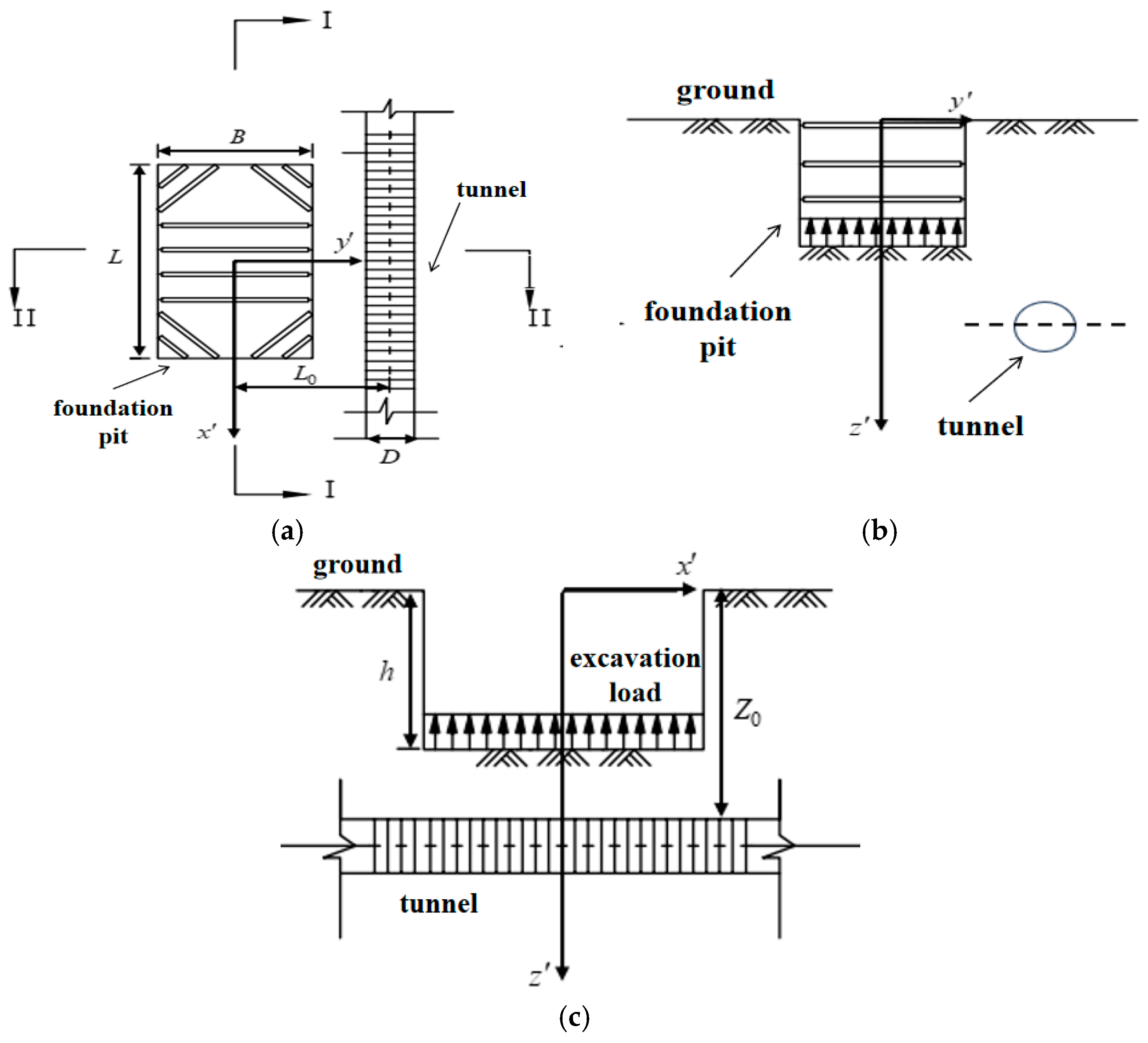
When the foundation pit and the tunnel are parallel, A schematic diagram of the simplified model of the foundation pit excavation and the underlying shield tunnel when the foundation pit is parallel to the tunnel is shown in Figure 1; a coordinate system is defined with its origin at the center of the excavation for the foundation pit. The foundation pit’s excavation length perpendicular to the tunnel axis was , while along the tunnel axis, it was , and the excavation depth was , The tunnel’s axis burial depth was ; the horizontal distance between the tunnel axis and the center of the foundation pit was ; the outer diameter of the shield tunnel was , and the excavation area of the foundation pit was . Thus, the exact position of any point along the tunnel’s axis was ().
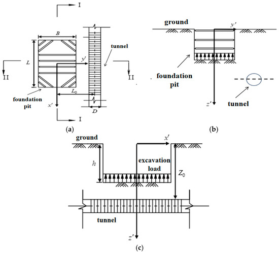
Figure 1.
(a) Plan view of the position relationship between the pit and the tunnel. (b) Section view I-I of the position relationship between the pit and the tunnel. (c) Section view II-II of the position relationship between the pit and the tunnel.
Here are the assumptions made [23]:
(1) The soil mass is considered an isotropic semi-infinite elastic entity.
(2) The impact of the tunnel’s presence on calculating extra stresses in the soil was not taken into account.
In actual engineering, above the tunnel, the foundation pit’s supporting structure exhibits considerable stiffness. Considering the shielding effect produced by the bottom building envelope and isolation wall, the influence of the lateral unloading of the foundation pit sidewall on the vertical deformation of the underlying shield tunnel can be disregarded. Therefore, the influence of the additional horizontal stress can be ignored.
Theoretically, given the assumptions outlined above, the mechanical effect of a foundation pit excavation can be viewed as the application of a uniformly distributed load that moves vertically upward at the foundation pit’s base. The uniformly distributed load is calculated using the following equation:
In the equation, (kN/m2) stands for the unloading amount at the bottom of the foundation pit, (kN/m2) represents the weighted average unit weight of the excavated soil, and is the residual stress coefficient proposed by Liu G.B. et al. [24], which is applied to evaluate scenarios where the stress at the pit’s base cannot be fully alleviated.
According to the fundamental solution by Mindlin [25], it can be known that under the action of the load () generated by a random point () at the bottom of the foundation pit, the vertical additional stress σz produced at a random point (x′, L0, Z0) on the tunnel axis is
where represents Poisson’s ratio of the soil mass.
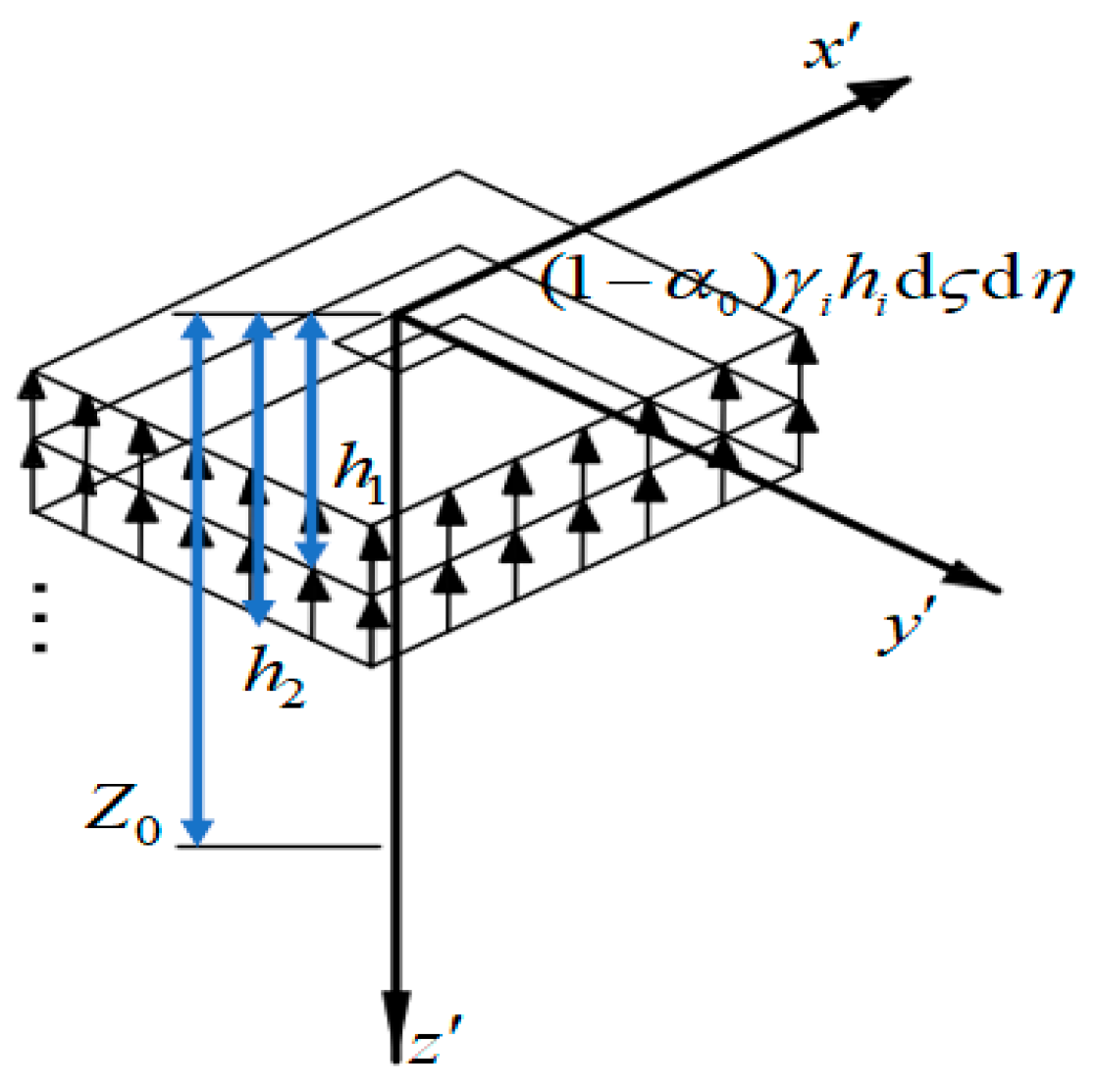
Tong X. et al. [26] indicated that in practical engineering, especially when a shield tunnel already exists under the foundation pit, the layer-by-layer excavation method is frequently used to gradually release the additional stress at the pit’s bottom, according to elastic layered theory. As shown in Figure 2, the soil layers were stratified to consider the depth of the load action of each soil layer more accurately. The action depth of the load of each layer and unit weight were used to replace and in Equation (2), respectively, and a more accurate additional stress was obtained through the method of stress superposition.

Figure 2.
Calculation model of additional stress under layered unloading.
In cases where the foundation pit and tunnel cross at an angle and the tunnel is positioned under the side of the foundation pit, considerations are made through coordinate transformation based on the coincidence of the axes of the two.
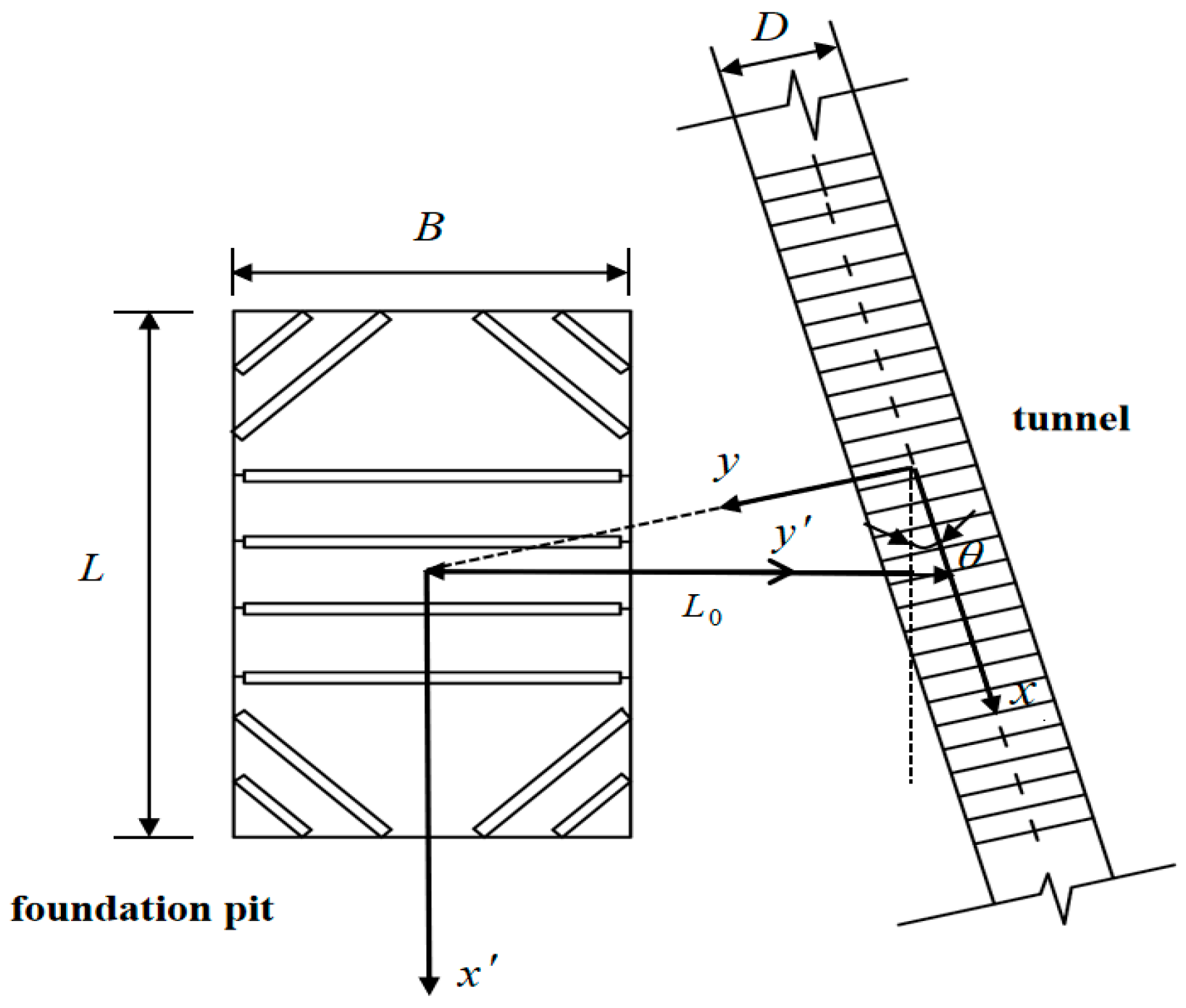
As illustrated in Figure 3, with the origin being the point on the tunnel axis closest to the foundation pit in the plane , the x-axis was aligned with the tunnel’s direction; the y-axis was set perpendicular to the tunnel, and the z-axis was defined as vertical to create the new coordinate system . The coordinates () of the points on the tunnel axis in the new coordinate system can be obtained through a coordinate transformation from the original coordinates () using the following equation:
where represents the angle between the tunnel axis and the x′-direction of the original coordinate system. When calculating, a positive value is taken in the clockwise direction, and a negative value in the counterclockwise direction.
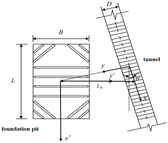
Figure 3.
Plan view of the oblique intersection calculation model between the pit and tunnel.
3. The Calculation of Longitudinal Deformation of Tunnels Considering the Rotation and Dislocation Between Segment Rings
3.1. The Deformation Model of the Tunnel Under the Synergy of Rotation and Dislocation
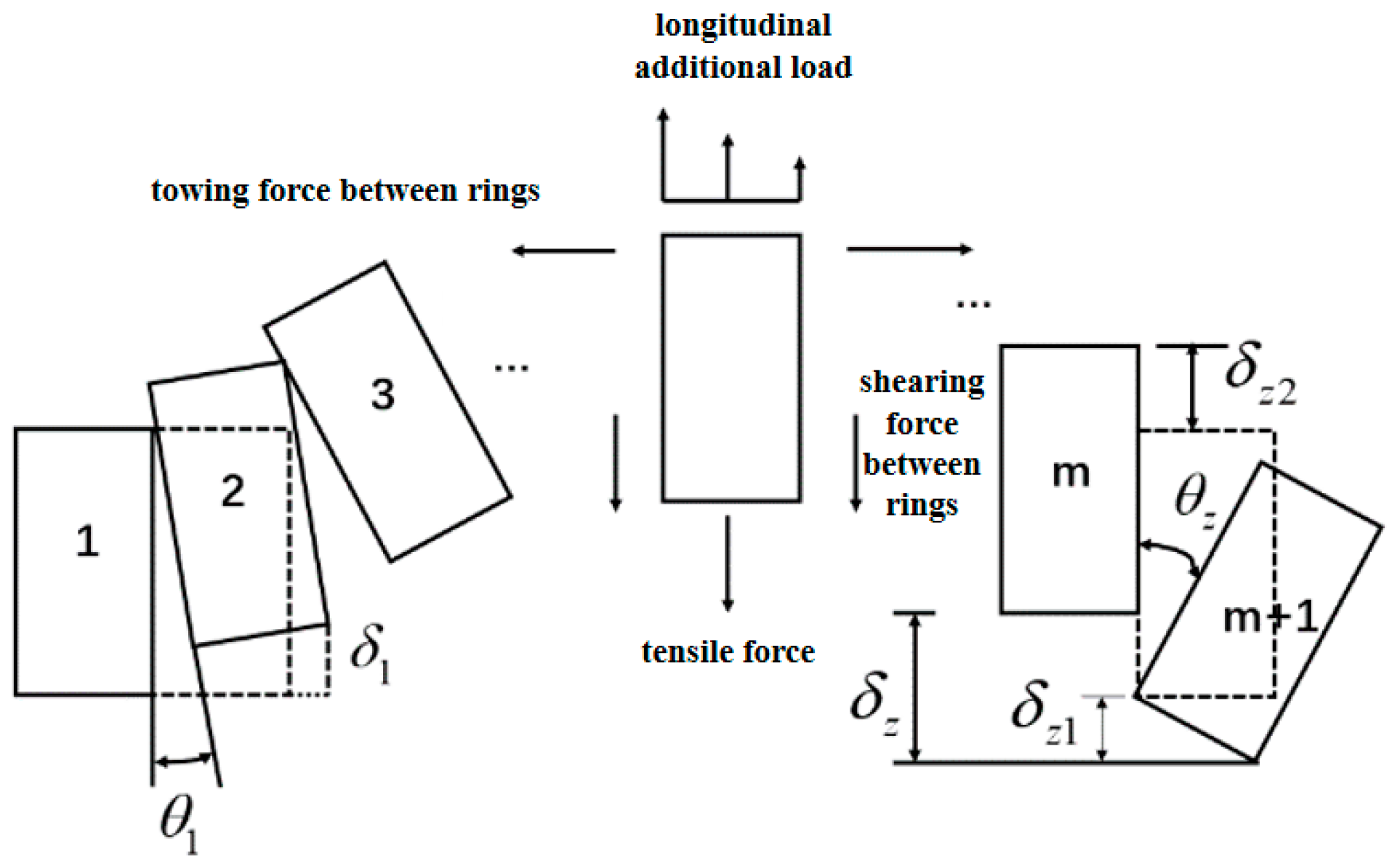
Zhang X.H. et al. [20] introduced a tunnel deformation model that accounts for the coordinated deformation involving the rotation and dislocation of shield tunnel segment rings. The shield tunnel under the foundation pit was considered a sequence of short beams with elastic foundations linked by normal and shear springs. Adjacent segments underwent relative rotation and dislocation, with shear dislocation and rigid body rotation contributing to the tunnel’s longitudinal deformation.
As depicted in Figure 4, denotes the entire vertical displacement between the m-th and (m + 1)-th segments. The vertical displacements originating from the rotation of the segment rings are denoted as , and the vertical displacements produced by the misalignment of the segment rings are denoted as . Thus, Equation is satisfied.
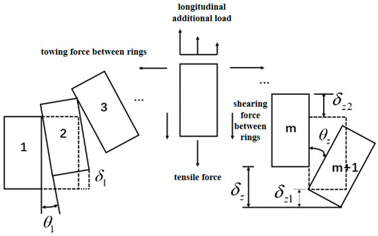
Figure 4.
Cooperative deformation calculation model for shield tunneling shearing dislocation and rigid body rotation.
Zhang X.H. et al. [27] proposed the proportion coefficient of the rotational effect of the ring stiffness of segments, namely , which reflects the ratio of vertical displacement caused by the rotation between adjacent segment rings to the entire vertical displacement. This conforms to the following equation:
When = 0, it is a deformation mode of complete shear misalignment. One can refer to the research on the tunnel misalignment model proposed by Zhou S.H. et al. [28]. When = 1, it is a complete rotational deformation mode of the rings of the segments, which is in accordance with the model adopted by Wang R.L. et al. [29] for calculating the opening amount of the gap of the tunnel segment rings.
Assuming that the shield tunnel beneath the foundation pit and the surrounding soil satisfy the deformation compatibility condition, the displacement of the tunnel is equal to that of the corresponding soil; thus, the subsequent equation can be formulated:
In the equation, indicates the computed location of the tunnel along the longitudinal axis in the new coordinate system, () depicts how the shield tunnel’s vertical displacement is distributed beneath the foundation pit, and () shows how the soil around the tunnel is vertically displaced along the tunnel’s axis.
The value of the vertical displacement difference between adjacent segments, namely , can be expressed as
In the equation, and identify the sequence numbers of rings in contiguous segments and represents the width of the rings in the segments.
Because the rotation angle between the segment rings is relatively small, the formula is given as sin () = , where cos () = 1. Thus, vertical displacement due to the rotation of segment rings can be articulated as
Substituting Formula (4) into Formula (7) gives
The equation for finding the shearing force between rings is
The equation used to determine the towing force between two rings is
The formula for computing the tensile force is
In the formula, denotes the shear stiffness between rings and denotes the tensile stiffness between rings, and the determination method of their values is based on the research by Guo L. et al. [30]; represents the foundation bed coefficient of the soil, which can be calculated using the formula by Vesic [31]:
In the equation, is the elastic modulus of the foundation soil; is the equivalent flexuous rigidity of the tunnel, which is based on the research by Li H.R. et al. [32]; is the elastic modulus of the shield tunnel lining failure; and is the inertial moment.
3.2. Total Potential Energy of Shield Tunnel Deformation
The total potential energy of the adjacent shield tunnel, influenced by the excavation of the foundation pit, is determined by the force conditions of each ring segment and includes four parts:
(1) Work of vertical stress increases after digging the foundation pit:
In this equation, 2N denotes the number of ring segments of the shield tunnel within the calculation range. Its significance is linked to the area influenced by the foundation pit excavation. Theoretically, a greater N value enhances calculation precision. However, the corresponding computational effort also increased. The specific value is elaborated in the parameter analysis; () represents the additional load on the tunnel from the soil. The calculation formula is as follows:
In the equation, denotes the diameter of the tunnel’s exterior.
(2) This overcomes the tensile force required to perform the work:
(3) In order to counter the shear force between the rings to execute the work,
(4) To overcome the towing force between the rings to perform work,
Substitute Formula (18) into Formula (17) to obtain Formula (19)
The total potential energy of the shield tunnel resulting from the foundation pit excavation can be calculated by integrating Equations (13)–(19):
3.3. The Longitudinal Displacement of the Shield Tunnel Is Expanded in Series
The vertical displacement of a shield tunnel is asymmetrical on its left and right sides when the foundation pit intersects it at an angle. When expanding it using a Fourier series, both sine and cosine parts should be included. The calculation method for the expansion is as follows:
In the equation,
In the Fourier series, matrices and are to be identified, while denotes the order of expansion.
In a simplified model where the foundation pit crosses the underlying shield tunnel at a right angle, the tunnel’s longitudinal deformation should theoretically be symmetrical around the midpoint of the foundation pit excavation, and it can be expanded in the Fourier series as a cosine function. Refer to Zhang X.H. for more information [27].
3.4. Solving Variational Control Equations
By substituting expansion Formula (21) of the tunnel displacement into Equation (20), which is centered around the principle of minimal potential energy, the extremum values of each undetermined coefficient are obtained as follows:
In the equation,
The variational control equation, addressing the impact of foundation pit excavation on the underlying tunnel by considering ring rotations and dislocations, is derive by solving Equation (23).
It is abbreviated in matrix form as
In the equation,
where [Kr] is the rotational and shear stiffness matrix between the rings of the segments, [Ks] is the soil stiffness matrix, and [P]T is the effect of the additional stress on the rings of the segments.
The undetermined coefficient matrix ()T can be calculated using Equation (25).
The longitudinal displacement function of the tunnel can be derived by substituting the obtained undetermined coefficient matrix ()T into Equation (21):
The calculation method of dislocation between adjacent segments is
Here is how to calculate the shear force between adjacent segments:
The calculation method of the rotation angle between adjacent segments is
During the above integral operation process, the integral steps were aided by the quad (adaptive Simpson’s integration method) instruction in MATLAB R2024a. The step size was chosen to satisfy the precision requirements, and the relative error was merely one thousandth.
4. Example Verification
4.1. Case 1 (Hangzhou Jiusha River Foundation Pit Project)
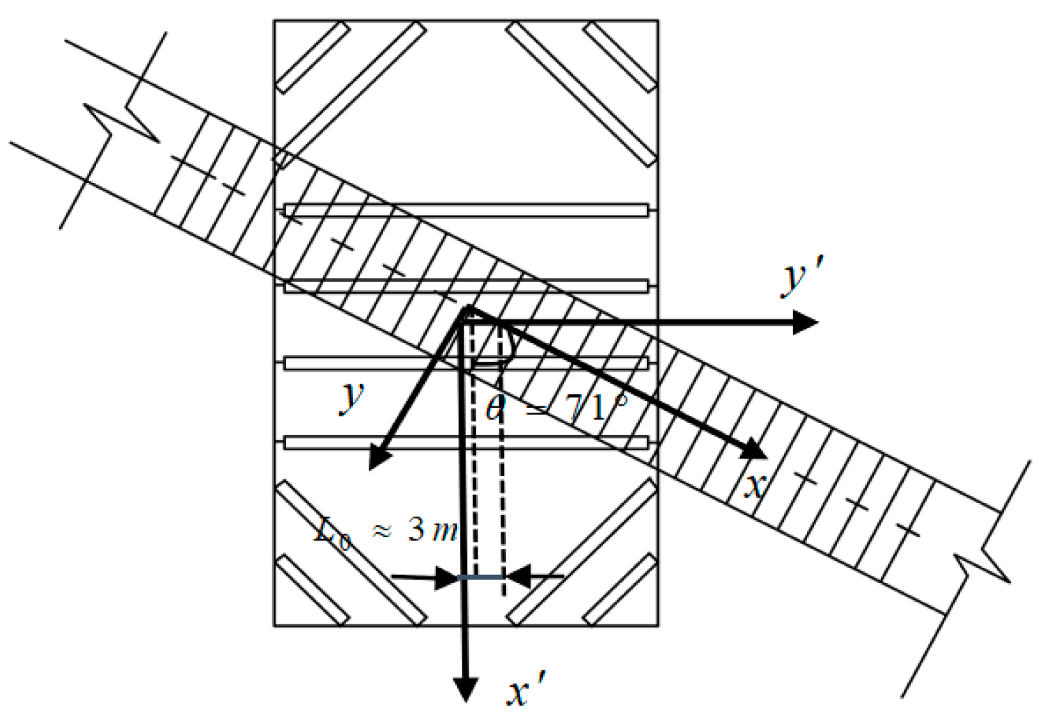
The foundation pit excavation project of the Jiusha River in Hangzhou crosses Metro Line 1. The plane oblique angle is = 71°; there is a distance of under 5 m between the center of the foundation pit and the tunnel axis, which is perceived as the oblique crossing between the foundation pit and the tunnel directly below; the length of the foundation pit is = 47.3 m; the width is = 46 m, the excavation depth is = 6.35 m, and the minimum clear distance from the top of the tunnel to the bottom of the pit is 3 m. The external diameter of the tunnel shield is = 6.2 m. C50 concrete segments are adopted, with a thickness of = 0.36 m and a ring width of = 1.2 m. The shear stiffness between rings is = 7.45 × 10⁵ kN·m−1, = 1.94 × 10⁶ kN·m−1, and = 1.1 × 10⁸ kN·m2 [8]. Figure 5 illustrates a simple planar relationship between the foundation pit and the tunnel.
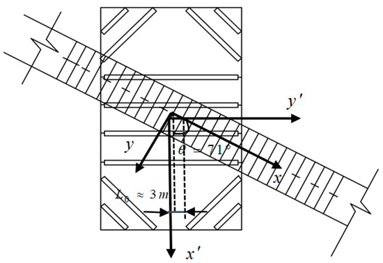
Figure 5.
Plan view of the oblique intersection calculation model between the pit and tunnel in Case 1.
Poisson’s ratio of soil is = 0.35. Reflecting on the reinforcing properties of cement soil, the constrained modulus is = 11.16 MPa. The coefficient of residual stress upon unloading was set as 0.3.
Refer to Table 1 for the presentation of soil parameters [1].

Table 1.
Case 1 site engineering geological parameters.
Figure 6 shows the vertical displacement curves of the tunnel calculated in Case 1 for both scenarios, with and without considering the oblique intersection of the tunnel and the foundation pit axis. As shown in Figure 6, when considering the oblique intersection, the maximum deformation of the tunnel, which is 5.535 m, occurs at a lateral coordinate value of 3.365 m. When an oblique intersection is not considered, the maximum deformation of the tunnel (5.492 m) occurs at a lateral coordinate value of 0 m. The maximum measured deformation of 5.507 m occurred at a lateral coordinate value of 3.093 m. The measured vertical displacement of the shield tunnel obtained via the calculation method in this study was essentially consistent with the variation pattern of the measured values, both exhibiting a distinct Gaussian normal distribution. The tunnel’s uplift range was between 60 and 65 m from the center of the foundation pit excavation on both sides. The longitudinal deformation range of the tunnel is associated with the excavation length of the foundation pit, and this connection was analyzed through parameter analysis. However, the traditional calculation method for the elastic foundation beam varies significantly from the measured values, demonstrating that the combined model of rotation and dislocation is more accurate. When the tunnel is situated directly beneath the foundation pit, the maximum vertical displacement varies by only 0.043 m, regardless of whether the oblique intersection between the foundation pit and the tunnel is taken into account, making it almost negligible.
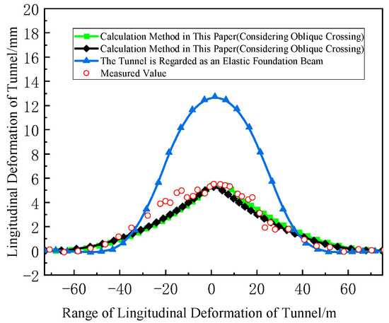
Figure 6.
Calculation and comparison of the longitudinal deformation of the shield tunnel in Case 1.
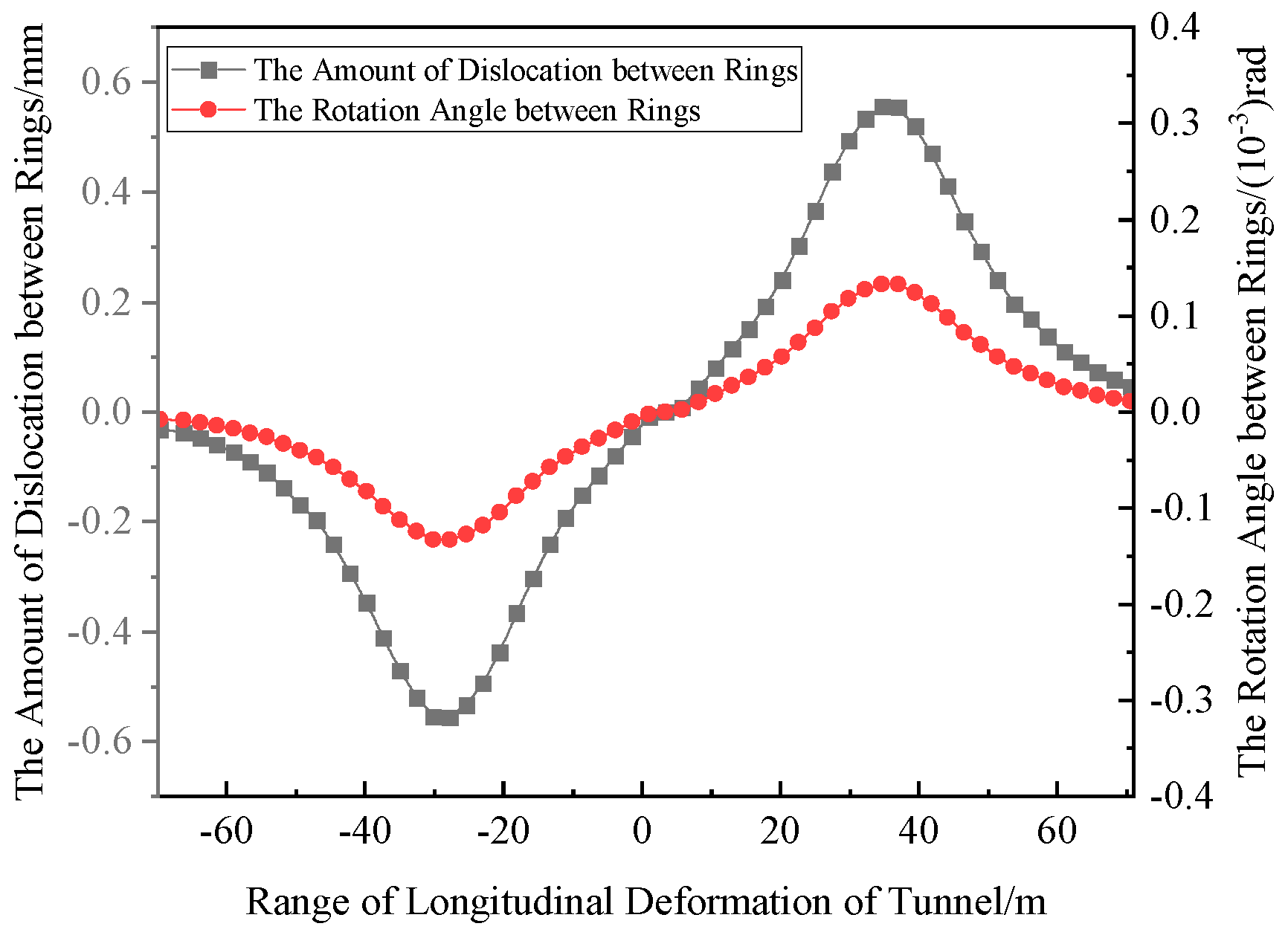
The dislocation and rotation angles of ring segments can impact the safety of the tunnel structure and its waterproofing system. Higher dislocation and rotation angles between the rings lead to a greater chance of water leaking in the tunnel. Zhang Z.G. et al. [33] carried out a grade classification for the safety assessment of the dislocation and rotation angle; thus, the calculation of the dislocation and rotation angle is of great significance. Figure 7 shows the dislocation and rotation angle of the tunnel calculated using the method in this study. The figure indicates that when the tunnel’s vertical displacement peaks, the dislocation and rotation angles between the rings are nearly zero, despite a sharp increase. The maximum dislocation of 0.555 mm and the largest rotation angle of 0.133 × 10⁻³ rad were observer at the inflection point of the tunnel’s vertical displacement curve, which is located about 37 m from the excavation center near the excavation area’s edge.
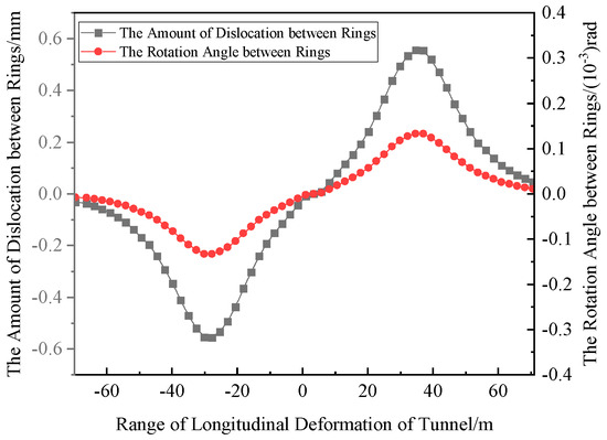
Figure 7.
Dislocation and rotation angle among shield tunnel segment rings in Case 1.
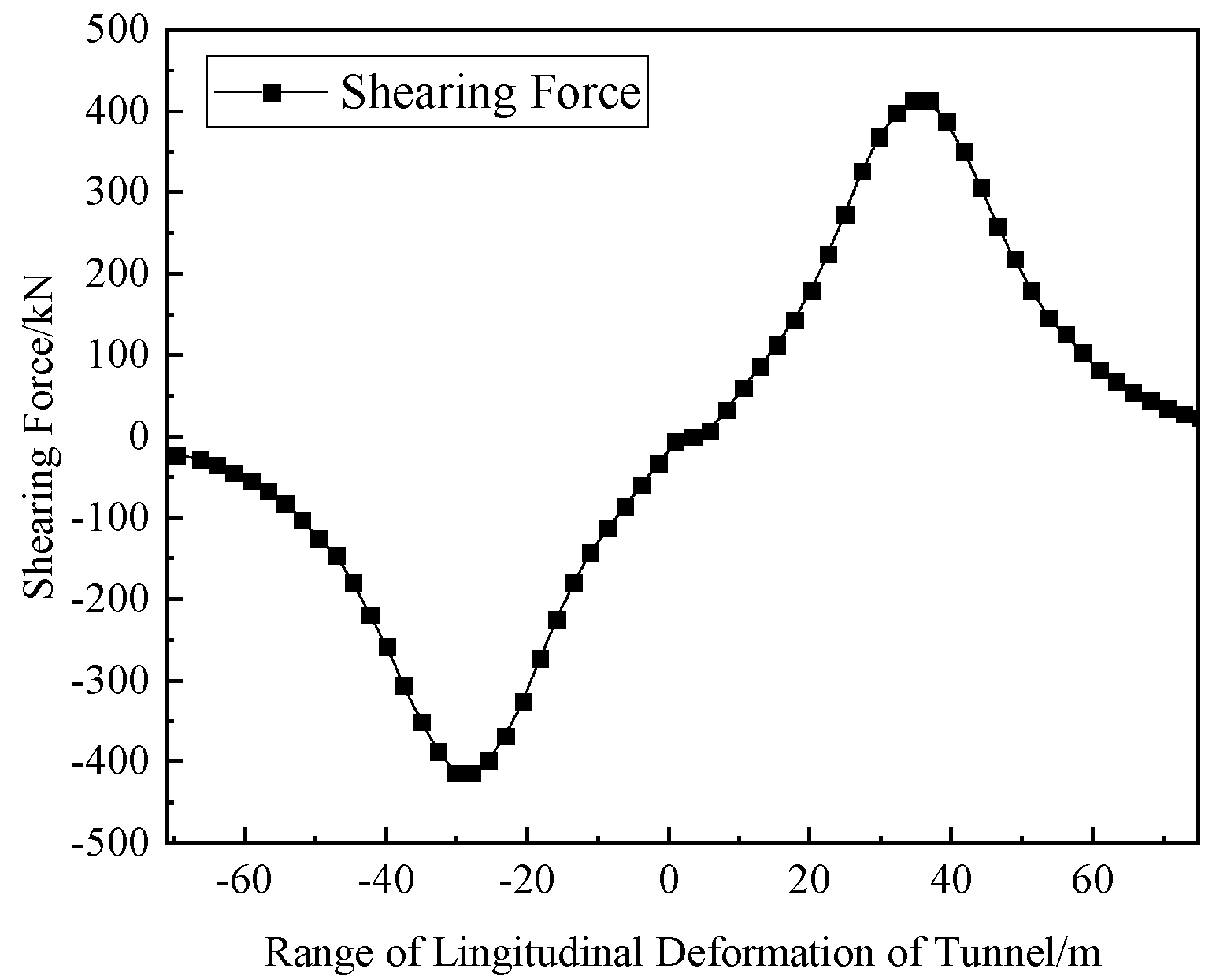
The shear forces between the tunnel rings, as calculated, are depicted in Figure 8. The variation pattern of the tunnel shear force was in accordance with that of the misalignment. The position with the maximum misalignment generated a maximum shearing force of 413.48 kN.
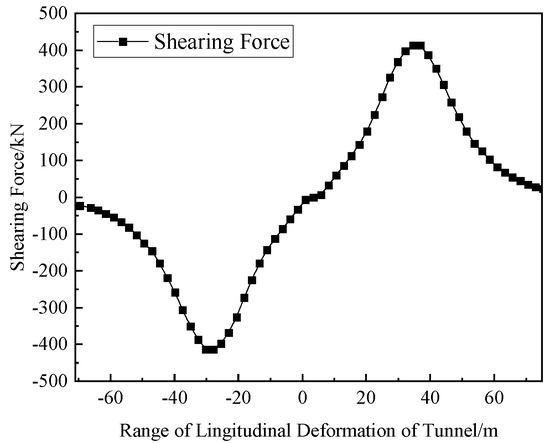
Figure 8.
Shearing force among shield tunnel segment rings in Case 1.
Based on the safety assessment grades [33], the safety assessment grade corresponding to the rotation angle was Grade II, and the assessment grade corresponding to the misalignment was Grade V, indicating certain safety risks. The shear force was also close to the maximum shear force that the bolts could withstand. Thus, monitoring, prevention, and control efforts must be implemented.
4.2. Case 2 (Shanghai Metro Line 2 Is Adjacent to the Foundation Pit)
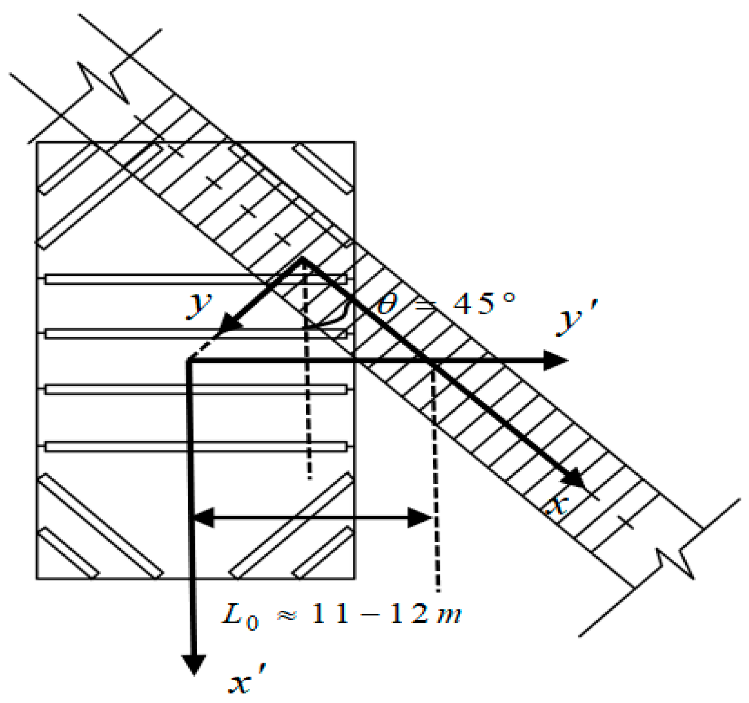
Shanghai Metro Line 2 is located beside the foundation pit. The plane oblique angle is = 45°. The tunnel axis is approximately 11–12 m away from the center of the foundation pit; the length of the foundation pit is = 26 m; the width is =18 m; the excavation depth is = 6.5 m, and there is a minimum clear distance of 2.76 m from the top of the tunnel to the bottom of the pit. The top of the tunnel has a burial depth of 9.3 m [28]. The shield tunnel’s external diameter is = 6.2 m, with a thickness of = 0.35 m and a ring width of = 1 m. The shear stiffness between rings is = 4 × 10⁵ kN·m−1, = 1.04 × 10⁶ kN·m−1, and = 5.34 × 10⁷ kN·m2. Figure 9 illustrates a simple planar relationship between the foundation pit and the tunnel.
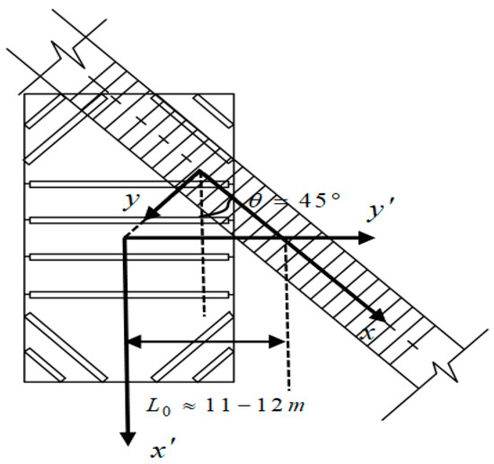
Figure 9.
Plan view of the oblique intersection calculation model between the pit and tunnel in Case 2.
Poisson’s ratio of soil is = 0.4. Considering the reinforcement effect of the cement soil, the constrained modulus is = 7.75 MPa. The coefficient of residual stress α0 upon unloading was set as 0.1.
Table 2 below displays the soil parameters [3].
Table 2.
Case 2 site engineering geological parameters.
Figure 10 depicts the tunnel displacement curves calculated in Case 2 under both oblique and non-oblique conditions, along with the tunnel displacement curve derived from the model’s degeneration in the shear model calculation. The overall orientation of the tunnel curves is in line with that of Case 1, presenting a normal distribution. The range of the tunnel heave extends 30–40 m on both sides from the center of the foundation pit excavation. As indicated in Figure 10, when the oblique condition is considered, the maximum tunnel deformation of 7.138 m emerges at the abscissa of 11.323 m; when the oblique condition is not taken into account, the maximum tunnel deformation of 2.32 m occurs at the abscissa of 0 m; the maximum tunnel deformation of 7.782 m in the shear model appears at the abscissa of 11.323 m; and the maximum measured deformation of 10.102 m occurs at the abscissa of 12.23 m.
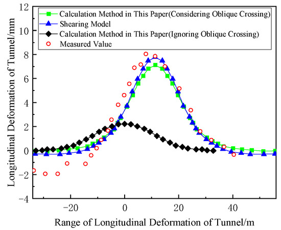
Figure 10.
Calculation and comparison of longitudinal deformation of the shield tunnel in Case 2.
In Case 2, the longitudinal displacement curves of the tunnel showed a significant variation based on whether the foundation pit was inclined relative to the tunnel. Figure 10 illustrates that considering obliquity aligns the shield tunnel displacement more closely with the measured values. The maximum displacement value calculated without considering obliquity is only 2.32 m, which is much smaller than the measured data. It is crucial to consider the angle between the foundation pit and the tunnel when the tunnel is not positioned directly beneath the foundation pit. The substantial difference arises because obliquity causes considerable variation in the distances of various segments from the foundation pit during calculations. This situation does not arise when the tunnel is positioned directly beneath the foundation pit.
Figure 10 also computes the displacement curve obtained by the shear model. Compared to the method applied in this research, the shear model’s calculation of maximum displacement is nearer to the observed value. This was because the proportion coefficient of the rotational effect of the segment ring stiffness, at = 0.2, was adopted in the calculation. In the actual engineering of Case 2, the displacement change in the tunnel is more significantly influenced by shear. It was demonstrated that adopting an appropriate for calculation is of great significance. Specific studies can be found in the section on parameter analysis.
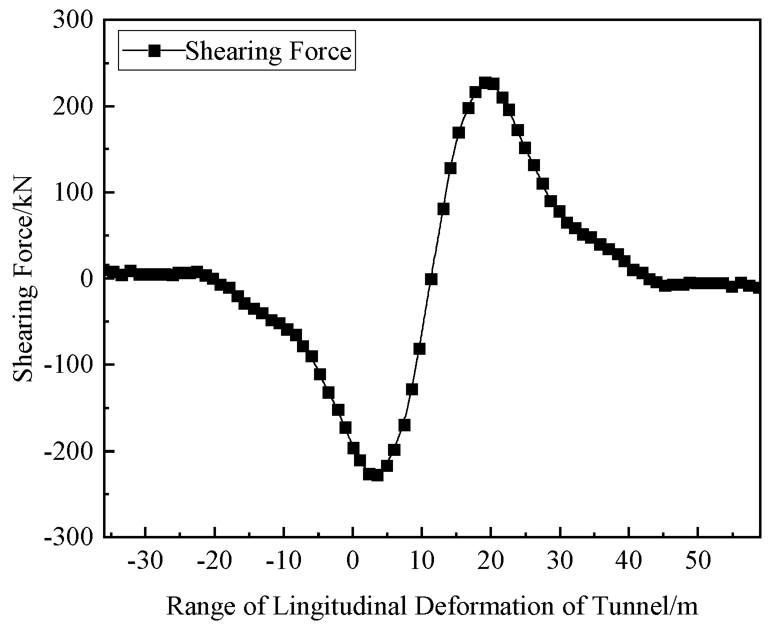
Figure 11 illustrates the calculated inter-ring dislocation amount and rotation angle for Case 2. The maximum inter-ring dislocation amount was 0.568 mm, and the maximum inter-ring rotation angle was 0.142 × 10⁻³ rad; both were observed at the turning point of the tunnel’s vertical displacement curve, roughly 3.5 m and 19 m from the center of excavation. Figure 12 shows the inter-ring shear force calculated for Case 2. The position with the largest dislocation amount generated a maximum shearing force of 227.32 kN. The curve pattern is consistent with that of Case 1.
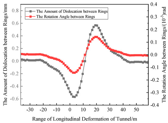
Figure 11.
Dislocation and rotation angle among shield tunnel segment rings in Case 2.
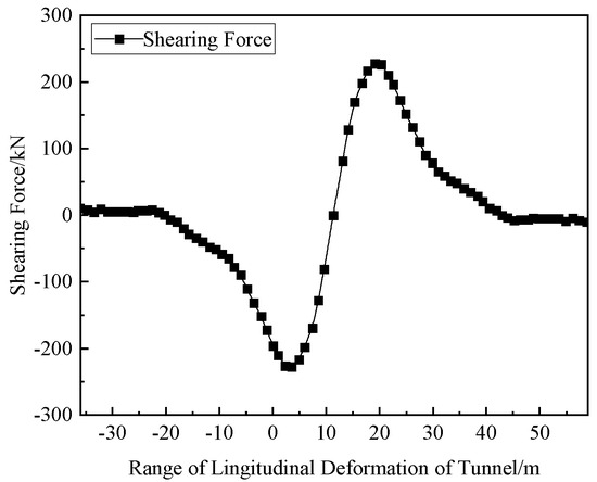
Figure 12.
Shearing force among shield tunnel segment rings in Case 2.
Based on the safety assessment grades [33], the safety assessment grade corresponding to the rotation angle was Level II, and the assessment grade corresponding to the dislocation amount was Level IV, indicating certain safety hazards. The shear force was less than the maximum shear force that the bolt could bear and was relatively safe.
5. Parameter Analysis
5.1. Proportion Coefficient of the Rigid Body Rotation Effect of Segment Rings
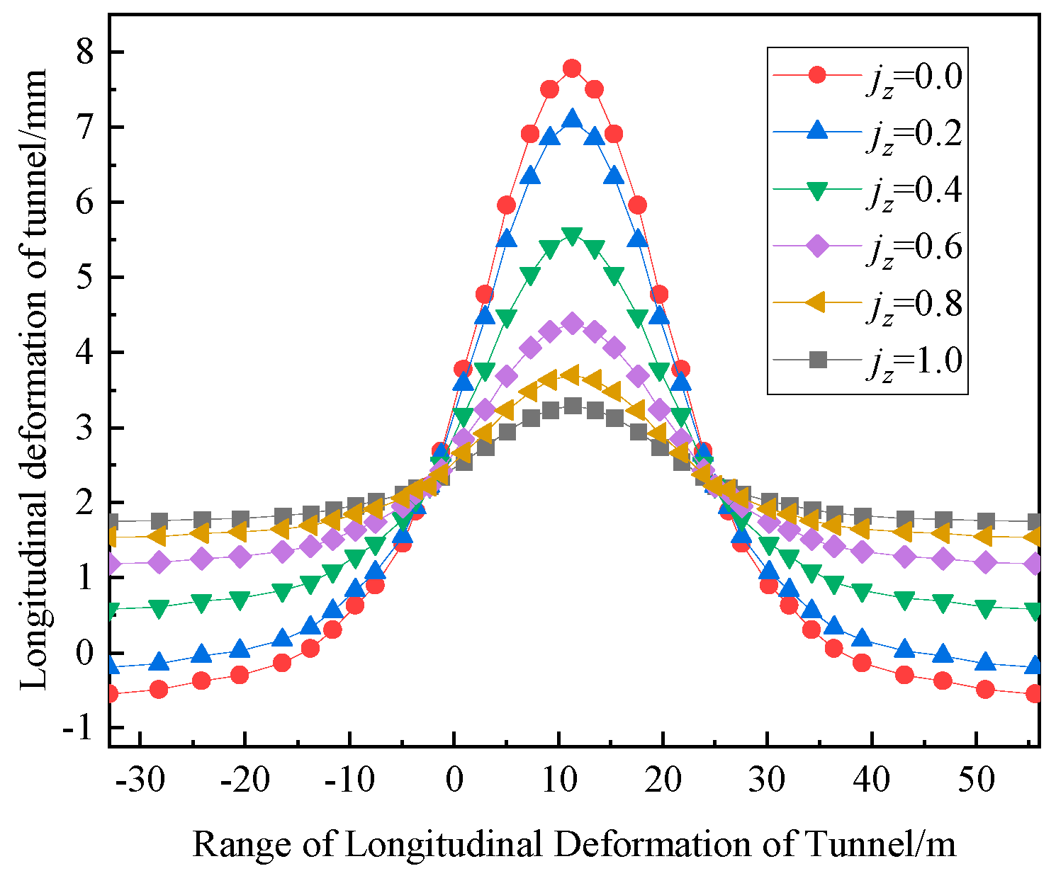
The model employed in this study is a model of the coordinated deformation of the ring dislocation of segments and rigid body rotation. is employed to indicate the proportion of vertical movement caused by the relative rotation between the rings of neighboring segments and the overall vertical movement. Taking Case 2 as an example, when only parameter was changed, the obtained tunnel deformation curve is presented in Figure 13.
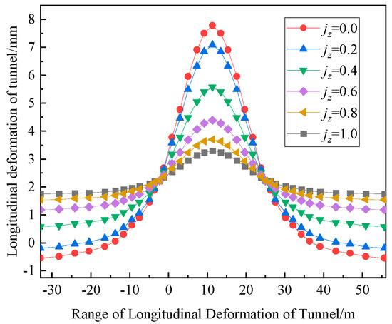
Figure 13.
Calculation and comparison of longitudinal heave deformation of the shield tunnel with different jz.
As shown in Figure 13, as increased, the maximum calculated longitudinal displacement gradually decreased; as a result of the foundation pit excavation, the extent of tunnel deformation widened. The longitudinal displacements of the tunnel calculated for the shear dislocation model ( = 0) and the rotational model (= 1) were 7.782 m and 3.292 m, respectively, with a difference of 4.49 m. For different values of , the curves resulted in an identical vertical displacement at the peak values of the dislocation and rotation angle. As is evident from Figure 13, multiple vertical displacement curves intersect at the same point on both sides.
Based on the long-term monitoring of the Shanghai subway tunnel deformation by Wang R.L. et al. [29] and the research findings by Zhang X.H. [27], the vertical displacement resulting from the rigid body rotation effect of the segment ring constitutes 10–30%, and the dislocation effect between the segment rings results in a displacement ranging from 70% to 90%. In practice, the more refined the calculated value of , the more accurate the calculated longitudinal displacement curve. To strike a balance between calculation accuracy and efficiency, in the case analysis, the calculated values when is 0.1, 0.2, and 0.3, respectively, are computed, and the optimal result is selected to minimize the error as much as possible.
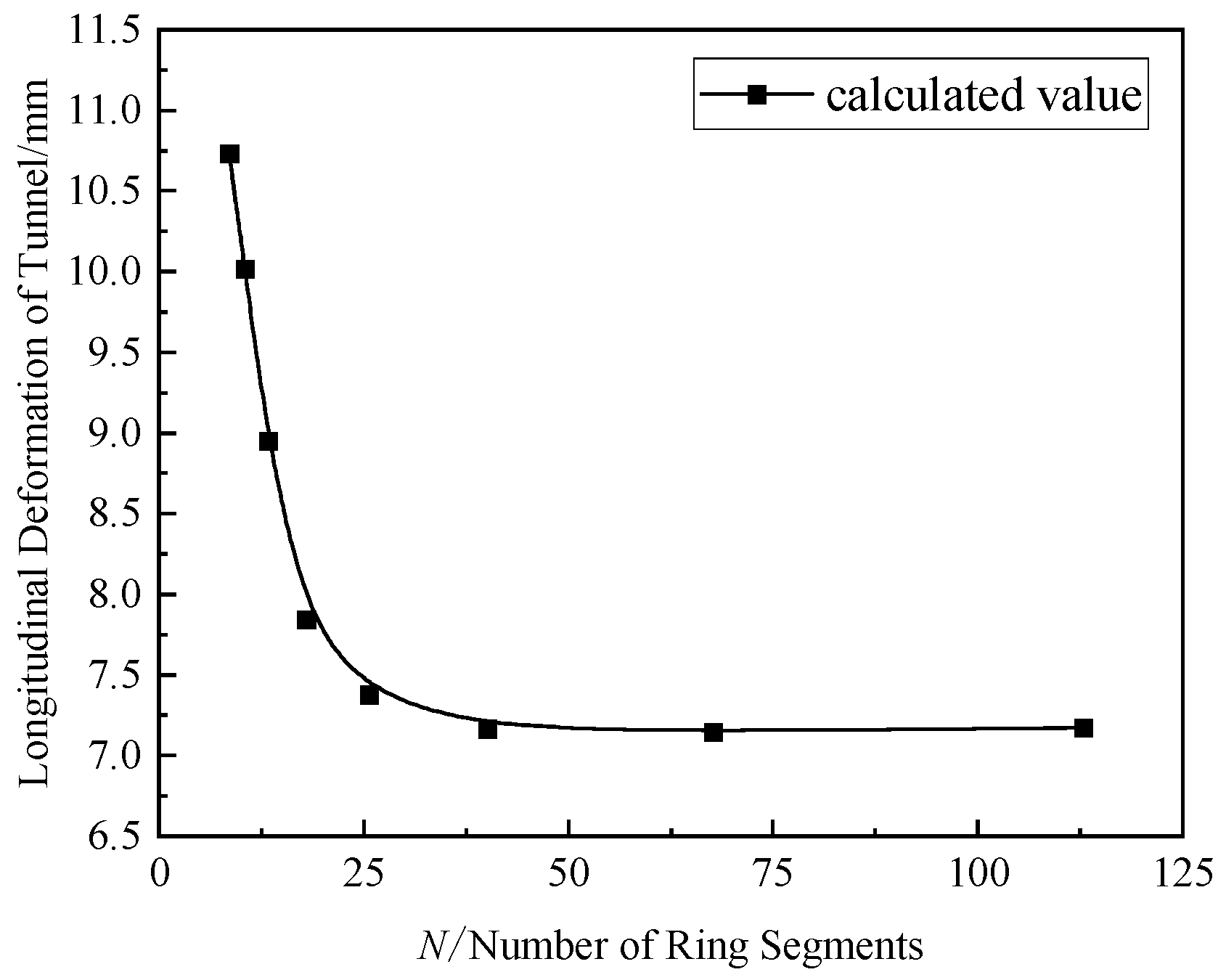
5.2. Number of Rings for Tunnel Segment Calculation
Within the calculation scope of the shield tunnel, denotes the number of ring segments. Theoretically, increasing the value of , which represents the extent of the foundation pit excavation’s impact on the tunnel, reduces calculation errors but decreases calculation efficiency. Taking Cases 1 and 2 in this study as examples, only the value of was altered, and the peak value of longitudinal deformation was determined.
The calculation results are presented in Figure 14 and Figure 15. As increased, the calculated maximum vertical displacement gradually converged, and the final converged value was close to the measured value. It can be deemed that at this point, the range has encompassed the influence range of tunnel deformation caused by foundation pit excavation in actual engineering.
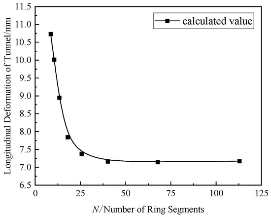
Figure 14.
Convergence of calculated maximum longitudinal deformation with different N values in Case 1.
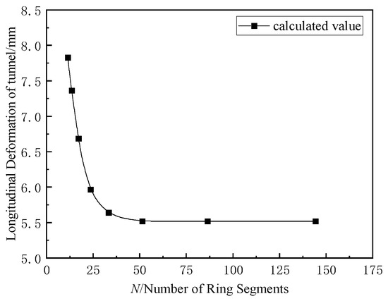
Figure 15.
Convergence of calculated maximum longitudinal deformation with different N values in Case 2.
In Case 1, the tunnel’s maximum vertical displacement stabilizes at approximately = 50, with the deformation range due to foundation pit excavation extending about 120 m. In Case 2, the computed peak vertical movement of the tunnel gradually levels off at around = 45, and excavating the foundation pit results in a tunnel deformation range of roughly 90 m. The maximum vertical displacement and influence range of the tunnel heave corresponded with the measured values. This approach can be employed to determine the N value for the calculation and to forecast the deformation range of the tunnel beneath due to the foundation pit excavation. Zhou S.H. et al. [28] determined from empirical data that the tunnel deformation angel on one side of the excavation center is roughly 2.2 times the length of the excavation. This conclusion can be used to determine the value required for rapid calculation.
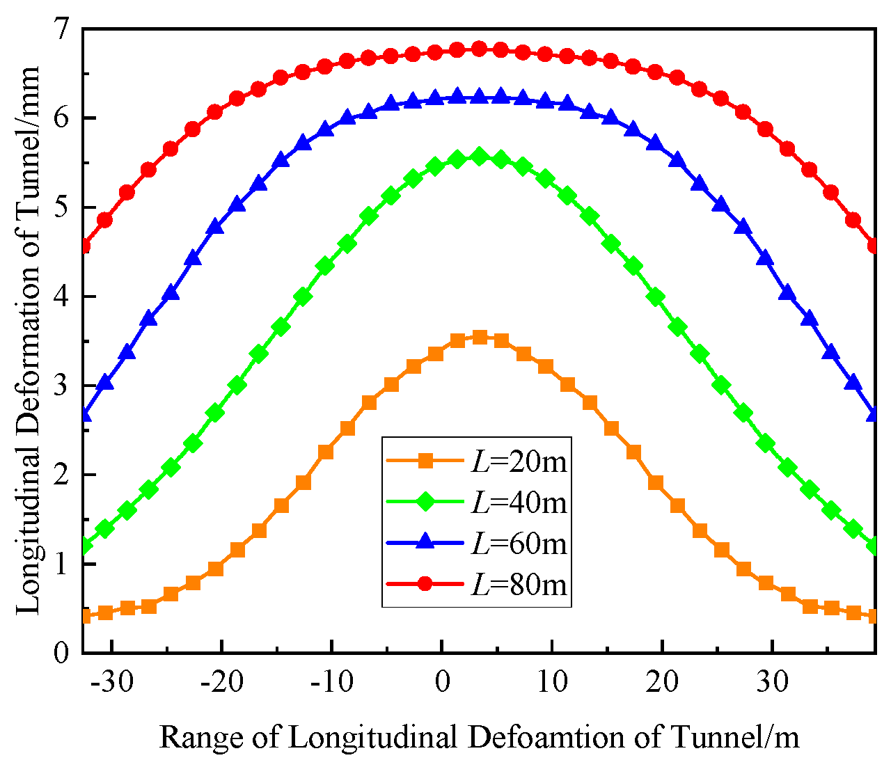
5.3. Excavation Length
The longitudinal deformation of the shield tunnel is depicted in Figure 16 under different values. It can be observed from Figure 16 that as increases and the tunnel’s longitudinal deformation value changes, the rate at which it increases diminishes. The tunnel’s uplift range grew as increased. Alterations in the uplift form and soil extent at the pit’s bottom are attributed to the expanded excavation width of the foundation pit, thereby causing an increase in the uplift range of the tunnel. The research was conducted by Ying H.W. et al. [34], who demonstrated that the ‘long-term excavation’ of the foundation pit affects the displacement and uplift range of the tunnel.
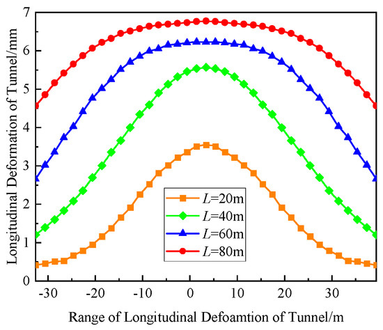
Figure 16.
Longitudinal deformation of the shield tunnel at different L values.
6. Conclusions
(1) The model accounting for coordinated deformation through segment ring rotation and dislocation aligns more closely with measured longitudinal displacement values of the underlying tunnel compared to the traditional homogeneous elastic foundation beam model. The coordinated deformation model, on the basis of accurately determining the proportionality coefficient of the rigid body rotation effect of the segment ring, aligns more closely with measured values than the shear dislocation and rigid body rotation models. This model more effectively demonstrates the impact of foundation pit excavation on the deformation of underlying tunnels in practical engineering scenarios.
(2) The vertical displacement of the angled tunnel followed a normal distribution, displaying asymmetry with respect to the center of the foundation pit excavation. The maximum vertical displacement coincides with minimal rotation and dislocation, while significant rotation angles and dislocation occur within a specific range around the inflection point of the displacement Gaussian curve.
(3) When the tunnel is directly beneath the foundation pit, calculation errors remain within 5%, even if the foundation pit and tunnel axes intersect obliquely, which is not significant. When the tunnel is located beneath the side of the foundation pit, neglecting the oblique intersection between the foundation pit’s axis and the tunnel can lead to calculation errors exceeding 300% compared to measured values. The calculations that account for the oblique intersection between the foundation pit axis and the tunnel align more closely with the actual engineering deformation patterns.
(4) In practical engineering, excavating the foundation pit significantly alters the stress distribution. The influence of the additional horizontal stress cannot be ignored. The influence factors, such as the time–space effect, precipitation, and retaining structures, are also worthy of consideration. The proportional coefficient for the rigid body rotation effect of the segment ring remains imprecise, warranting further research.
Author Contributions
Software, Y.T.; formal analysis, Y.T. and M.C.; investigation, P.C.; writing—original draft, Y.T.; writing—review and editing, D.W.; project administration, D.W.; funding acquisition, D.W. All authors have read and agreed to the published version of the manuscript.
Funding
This study was supported by the National Natural Science Foundation of China (grant number: 52238009).
Data Availability Statement
The data that support the findings of this study are available from the corresponding author upon reasonable request.
Acknowledgments
Special thanks are given to the editors and anonymous reviewers for their valuable comments and suggestions.
Conflicts of Interest
The authors declare no conflict of interest.
References
- Li, J.Y.; Pan, L.D.; Hu, M.Y.; Peng, K.S. A modified calculation method of heave deformation of underlying tunnel caused by excavation. Chin. J. Ground Improv. 2019, 1, 10–19. [Google Scholar]
- Wei, G.; Hu, L.W.; Chen, K.L. Numerical Simulation of Effect of Foundation Pit Excavation on Underlain Shield Tunnel. In Proceedings of the 4th International Conference on Civil Engineering, Architecture and Building Materials (CEABM), Haikou, China, 24–25 May 2014; pp. 1001–1007. [Google Scholar]
- Xu, L.; Huang, H.W. Effect of foundation pit excavation on underlying metro tunnels. Chin. J. Geotech. Eng. 2008, 30 (Suppl. S1), 164–166. [Google Scholar]
- Huang, J.Z.; Liu, J.Z.X.; Guo, K.; Wu, C.; Yang, S.; Luo, M.X.; Lu, Y.N. Numerical Simulation Study on the Impact of Deep Foundation Pit Excavation on Adjacent Rail Transit Structures—A Case Study. Buildings 2024, 14, 1853. [Google Scholar] [CrossRef]
- Ding, Z.; Zhang, X.; Yin, X.S.; Jiang, J.Q. Analysis of the influence of soft soil grouting on the metro tunnel based on field measurement. Eng. Comput. 2019, 36, 1522–1541. [Google Scholar]
- Sun, H.S.; Chen, Y.D.; Zhang, J.H.; Kuang, T.S. Analytical investigation of tunnel deformation caused by circular foundation pit excavation. Comput. Geotech. 2019, 106, 193–198. [Google Scholar]
- Liang, R.Z.; Wu, W.B.; Yu, F.; Jiang, G.S.; Liu, J.W. Simplified method for evaluating shield tunnel deformation due to adjacent excavation. Tunn. Undergr. Space Technol. 2018, 71, 94–105. [Google Scholar]
- Liu, J.W.; Shi, C.H.; Lei, M.F.; Cao, C.Y.; Lin, Y.X. Improved analytical method for evaluating the responses of a shield tunnel to adjacent excavations and its application. Tunn. Undergr. Space Technol. 2020, 98, 103339. [Google Scholar]
- Wang, L.; Zheng, G.; Ou, R.N. Effect of jet grouting and dewatering on an adjacent tunnel in a Shanghai deep excavation. Proc. Inst. Civ. Eng.-Ground Improv. 2019, 172, 274–284. [Google Scholar]
- Wang, L.; Xu, P.; Ma, Z.S.; Yang, R.S.; Liu, P.F. Analysis of the Impact of Foundation Pit Construction on the Deformation of Underlying Metro Tunnels. Transp. Res. Rec. 2024. [Google Scholar] [CrossRef]
- Ding, H.B.; Wang, X.P.; Tong, L.H.; Lu, Q.; Xu, C.J.; Guang, L.X. Performance of isolation piles in protecting subway tunnels adjacent to foundation pits: Experimental and numerical investigations. Tunn. Undergr. Space Technol. 2025, 156, 106221. [Google Scholar]
- He, J.R.; Cheng, X.S.; Zhang, G.W. Model test of foundation pit excavation adjacent to the existing double-lane tunnel. Eng. Res. Express 2024, 6, 045110. [Google Scholar]
- Xu, T.; Zhao, D.Y.; Tao, H.W.; Lei, P. Extended CFD models for numerical simulation of tunnel fire under natural ventilation: Comparative analysis and experimental verification. Case Stud. Therm. Eng. 2022, 31, 101815. [Google Scholar]
- Liu, Z.; Wang, X.L.; Cheng, Z.F.; Sun, R.R.; Zharig, A.L. Simulation of construction ventilation in deep diversion tunnels using Euler-Lagrange method. Comput. Fluids 2014, 105, 28–38. [Google Scholar]
- Zhang, Z.G.; Huang, M.S.; Wang, W.D. Evaluation of deformation response for adjacent tunnels due to soil unloading in excavation engineering. Tunn. Undergr. Space Technol. 2013, 38, 244–253. [Google Scholar]
- Liang, R.Z. Simplified analytical method for evaluating the effects of overcrossing tunnelling on existing shield tunnels using the nonlinear Pasternak foundation model. Soils Found. 2019, 59, 1711–1727. [Google Scholar]
- Liang, R.Z.; Xia, T.D.; Huang, M.S.; Lin, C.G. Simplified analytical method for evaluating the effects of adjacent excavation on shield tunnel considering the shearing effect. Comput. Geotech. 2017, 81, 167–187. [Google Scholar]
- Timoshenko, S.P. On the correction for shear of the differential equation for transverse vibrations of prismatic bars. Philos. Mag. 1921, 41, 744–746. [Google Scholar]
- Wei, X.J.; Ma, J.H.; Wang, X.; Yan, Z.H.; Yan, J.J.; Wei, G. Evaluation of the Additional Stress on Adjacent Tunnel Shafts Induced by Foundation Pit Excavation. Adv. Civ. Eng. 2024, 2024, 890483. [Google Scholar]
- Zhang, X.H.; Wei, G.; Lin, X.B.; Xia, C.; Wei, X.J. Transverse Force Analysis of Adjacent Shield Tunnel Caused by Foundation Pit Excavation Considering Deformation of Retaining Structures. Symmetry 2021, 13, 1478. [Google Scholar] [CrossRef]
- Liu, X.Q.; Liang, F.Y.; Zhang, H.; Chu, F. Energy variational solution for settlement of buried pipeline induced by tunneling. Rock Soil Mech. 2014, 35 (Suppl. S2), 217–222+231. [Google Scholar]
- Shen, S.L.; Wu, H.N.; Cui, Y.J.; Yin, Z.Y. Long-term settlement behaviour of metro tunnels in the soft deposits of Shanghai. Tunn. Undergr. Space Technol. 2014, 40, 309–323. [Google Scholar]
- Zhang, J.F.; Chen, J.J.; Wang, J.H.; Zhu, Y.F. Prediction of tunnel displacement induced by adjacent excavation in soft soil. Tunn. Undergr. Space Technol. 2013, 36, 24–33. [Google Scholar]
- Liu, G.B.; Hou, X.Y. Residual stress analysis of uplift deformation due to soft soil excavation. Undergr. Eng. Tunn. 1996, (02), 2–7. [Google Scholar]
- Mindlin, R.D. Force at a Point in the Interior of a Semi-Infinite Solid. Physics 1936, 7, 195–202. [Google Scholar] [CrossRef]
- Tong, X.; Yuan, J.; Jiang, Y.X.; Liu, X.W.; Li, Y. Calculation of layered unloading additional stress of foundation pit based on Mindlin solution and the analysis of multiple factors influencing the rebound deformation. Rock Soil Mech. 2020, 41, 2432–2440. [Google Scholar]
- Zhang, X.H. Study on the Influence of Foundation Pit Excavation on the Stress and Deformation of Shield Tunnel Structure. Master’s Thesis, Zhejiang University, Hangzhou, China, 2022. [Google Scholar]
- Zhou, S.H.; He, C.; Xiao, J. Energy Method for Calculating Deformation of Adjacent Shield Tunnels due to Foundation Pit Excavation Considering Step between Rings. China Railw. Sci. 2016, 37, 53–60. [Google Scholar]
- Wang, R.L. Factors influencing deformation of Shanghai soft soil metro tunnel and deformation analysis. Undergr. Eng. Tunn. 2009, 1–6+52. [Google Scholar]
- Guo, L.; Yang, X.A.; Qiu, Y. Longitudinal heterogeneous equivalent continuous model for stagger joint segmental lining. Urban Mass Transit 2017, 20, 17–22. [Google Scholar]
- Vesic, A.B. Bending of beams resting on isotropic elastic solids. J. Eng. Mech. 1961, 87, 35–53. [Google Scholar]
- Li, H.R.; Ye, F.; Han, X.B.; Han, X. Comparative Analysis of the Numerical Simulation and Measured Data of an Existing Tunnel Subjected to Multiple Disturbances: A Case Study. Appl. Sci. 2024, 14, 4717. [Google Scholar] [CrossRef]
- Zhang, Z.G.; Cheng, Z.X.; Zhang, M.X. Dislocation deformation for existing tunnel longitudinal structure induced by shield tunneling by under-crossing type considering influence of lining permeability. China J. Highw. Transp. 2022, 35, 180–194. [Google Scholar]
- Ying, H.W.; Cheng, K.; Yu, J.L.; Xu, R.Q.; Qiu, Z.J.; Zhan, X.B.; Qing, J.S.; Lou, C.H. Prediction of shield tunnel displacement due to adjacent basement excavation considering continues deformation of ground. J. Zhejiang Univ. 2021, 55, 318–329. [Google Scholar]


Disclaimer/Publisher’s Note: The statements, opinions and data contained in all publications are solely those of the individual author(s) and contributor(s) and not of MDPI and/or the editor(s). MDPI and/or the editor(s) disclaim responsibility for any injury to people or property resulting from any ideas, methods, instructions or products referred to in the content. |
© 2025 by the authors. Licensee MDPI, Basel, Switzerland. This article is an open access article distributed under the terms and conditions of the Creative Commons Attribution (CC BY) license (https://creativecommons.org/licenses/by/4.0/).