Abstract
Throughout human settlement history, the pursuit of durability has been a paramount objective in building construction. The emphasis on durability has resulted in the construction of buildings designed to outlast human lifespans. However, the lack of consideration for building demolition and disposal during the design and construction phases has created challenges for future generations. This oversight contributes to the environmental impact of structures after demolition, which is a significant concern given that the construction industry is a major contributor to energy consumption, CO2 emissions, and solid waste production. In fact, in recent decades, there has been an increasing demand for temporary constructions, driven by factors such as migration phenomena, natural disasters, and the COVID-19 pandemic, but also in sectors like agriculture, where seasonality and annual variations in activities require adaptable structures such as warehouses, barns, livestock shelters, and food storage facilities. Unlike traditional constructions, these temporary buildings must be assembled and disassembled multiple times during their lifespan. The challenge lies in ensuring the structural integrity, adaptability to varying conditions, and compliance with specific requirements to extend their usability and postpone the disposal phase. This study focuses on the design of a novel type of temporary structures intended for temporary needs such as emergencies and planned agricultural activities, resulting in a European patent. The structure is based on a glulam frame inside two OSB panels—that work as structural bracing, creating a hollow, resistant, light structure—connected with external steel connections. This work reports results of mechanical simulations and thermal transmittance calculations. Specifically, it demonstrates the building maintains structural strength through multiple usages and its thermal characteristics can be easily adapted to the context. These are the first steps for a resilient and sustainable building.
1. Introduction
Since humanity started to build settlements, durability has been one of the most important characteristics to pursue in buildings. As houses have hosted people permanently, they were built to resist the surrounding environment, ensuring a safe shelter even in case of extreme conditions mainly due to snow, severe wind, rainfall, fire, seismic events, and more. The pursuit of durability and the need to reduce building maintenance have driven people involved in construction to use more and more resistant materials (stone, brick, steel, concrete) and to develop durability-oriented techniques [1].
Also, considering that the residents’ needs could remain unchanged for decades, buildings were designed to last more than a human lifespan, intending to be safe, solid, and resistant, but at the same time, hard to modify and dispose. As a matter of fact, building demolition and disposal phases have not been taken into account during the design phase, thus leaving such a problem to future generations and contributing to the increase in the environmental impact of the structure after demolition [2,3,4].
This high level of waste generation stems from the industrial paradigm, dependent on a linear economic model, based on the unsustainable principle of take, make, and dispose. If this model remains unchanged, projections suggest that global material consumption in cities will significantly increase from 40 billion tons in 2010 to 90 billion tons by 2050, continuing along current trends. Furthermore, considering the increasing world population and the migration towards urbanized areas, new buildings will be needed, and the matter of buildings’ end-of-life can no longer be avoided. Recognizing the need for a radical change in approach, the circular economy becomes fundamental to change at the industrial production level. In fact, sustainable design is considered the key to achieving certain objectives, providing the constant maintenance, repair, reuse, remanufacturing, refurbishment, and recycling of buildings and related parts [5,6], in particular in prefabricated timber buildings [7,8,9,10].
In accordance with sustainability objectives, architectural and construction design approaches, principles, and methodologies have been developed to facilitate the dismantling, decommissioning, and above all, the recovery of materials at the end of the building’s lifecycle [3,11,12].
This change could reduce global CO2 emissions from materials by 38%, equivalent to two billion tons, by 2050, mainly due to the reduction in demand and need for steel, aluminium, concrete, and plastic.
The latter is a fundamental remark. In fact, as is well-known, the construction industry is responsible for over 40% of energy consumption and 36% of CO2 emissions in Europe [13], and for over 23% of the solid waste production in total EU waste generation [14]. But the operations of building construction and demolition are undervalued aspects. As matter of fact, over 50% of the total waste produced by a building is generated after demolition. Furthermore, considering the increasing world population and the migration towards urbanized areas, new buildings will be needed, and the matter of buildings’ end-of-life can no longer be avoided.
Moreover, in the last decades, users’ needs have been changed and now buildings should meet renewed requirements, and some of them are even at odds with common building characteristics. For example, in the last decades, societies need more and more temporary constructions, mainly for emergencies and for seasonal activity purposes. Migration phenomena, natural disasters, and even the recent worldwide COVID-19 pandemic situation, are highlighting the urgency to have flexible structures built and made available in a short time and then deconstructed when the emergencies are over without leaving a permanent footprint on the territory. Constructions with similar characteristics are required as well in other sectors, e.g., in agriculture, where seasonality and annuity play a role in the hosted activities. In fact, the design of buildings like warehouses, barns, livestock shelters, and food storehouses would be connected to crop production or animal production, in a context where quantity and dimension can easily vary every year, season, or even month.
As better explained in the following, the same temporary structure should be assembled and disassembled many times during its life and can be placed in different locations for different purposes; therefore, contrarily to what happens for traditional constructions, temporary buildings must ensure the conservation of the structural performance and the possibility to be adapted according to the site in order to extend their life and delay the moment of disposal.
In the field of sustainability, today, the reuse of parts of buildings, especially wood, in the design of new buildings, has become a hot topic because it is presented as a proposal for a circular solution to support sustainable development. In fact, wood is a building material that is considered to be sustainable and can be easily deconstructed if designed and assembled correctly [15,16].
Furthermore, industrialized wood construction systems, especially 2D panel frames, have demonstrated an intrinsic adaptability that allows reconfiguration without demolition. The standardization of their easily assembled components implies efficient disassembly, depending on the nature of the connections between the elements. In fact, Torres et al. [3] estimated the disassembly characteristics of prefabricated light timber frame walls by assessing their recoverability, reusability, and recyclability down to the product level, boosting a transition to more regenerative and environmentally friendly building practices. Moreover, the lightweight nature of wood, with its versatility and efficiency in production, stimulates modular construction processes, providing a sustainable solution to the growing demands of the construction industry. As stated in Tenòrio et al. [17], regarding modularity trends in timber structures, the initial prevalence of 2D and 3D systems has given way to an increase in beam and column structures, mirroring the ascending verticality of buildings.
The present work focuses on an innovative system developed for temporary structures designed to meet requirements of both unplanned/unwanted situations, such as emergencies, and planned situations, such as agricultural activities; this has led to the development of a patent [18], with a specific attention to the conservation of the structural capacity after multiple usages. The structure is based on a wooden panel made by a glulam frame inside two OSB panels that work as a structural bracing, creating a hollow, resistant, and light structure. In particular, the proposed structure addresses structural and sustainability concerns by extending usability and delaying disposal, thus minimizing waste and reducing the carbon footprint. This paper reports structural analyses and thermal characteristic calculations, which are also based on experimental evidence.
Further, this study will consider structural, thermal, and acoustic experimental tests aimed at increasing the TRL of the proposed solution.
2. Materials and Methods
2.1. Characteristics of Temporary Buildings
Since the definitions of “temporary” and “emergency” buildings are not globally shared, this section aims at giving a first definition of these terms and other concepts that are valid for this study and are at the basis of the proposed building system.
The first definition concerns the concept of temporary. In fact, a temporary building is a structure that hosts a temporary function [19]. On the other side, an emergency can be considered “an unexpected and difficult or dangerous situation, especially an accident, which happens suddenly, and which requires quick action to deal with it” [20].
Under this light, “emergency” can be considered a subset of “temporary”, and the definitions are not related to the building characteristics (such as dimension, durability, materials, etc.) but to the hosted function only. Hence, in this section, we define the concepts and the requirements that an emergency structure should meet, the related characteristics, and finally the solutions applied to the proposed structure.
Given what was said in the introduction, in order to have an efficient and environmentally friendly temporary building, the structure should be reusable (in different places for different needs), the intervention should be reversible (the impact on the site should be minimized), and low-impact solutions should be chosen for materials and construction technology. These concepts entail the following requirements for a temporary building:
- -
- the construction should be easy to be installed and transported;
- -
- materials should ensure long structural resistance;
- -
- the construction should be adaptable for installation in different locations and for different intended uses and easy to remove;
- -
- specific attention should be paid to the environmental impact during all the following phases: design, production, transportation, construction, operating, removal, and disposal.
For a global comprehension, please see Figure 1. The identified characteristics that meet the abovesaid requirements are as follows:
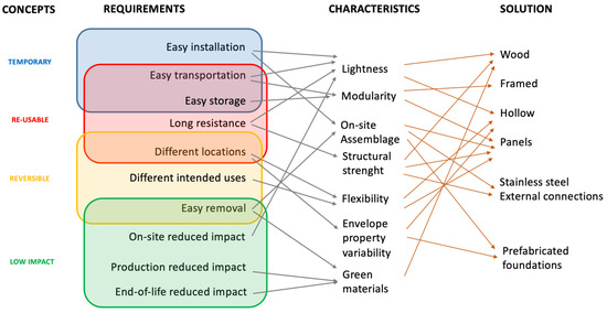
Figure 1.
Modular building technology: a conceptual scheme.
- -
- lightness (to ease the transporting, storing, assembling, disassembling operations);
- -
- modularity (to be flexible, easy to transport, and store);
- -
- on-site assembling (to avoid difficult transportation and to ensure more configurations of the building);
- -
- despite the “temporary” nature, structural strength plays an important role to ensure a long life to the structure;
- -
- flexibility to ensure the possibility to be built also in severe environments and serve different purposes;
- -
- the external envelope should offer the possibility to be adapted to the purposes (mainly in terms of thermal and acoustics properties);
- -
- construction materials should be chosen while taking into account their production and disposal, in order to minimize the global environmental impacts of the solution.
2.1.1. Lightness
Lightness is a characteristic of the techniques that temporary construction cannot ignore. Lightness, in fact, ensures the speed and ease of installation, as well as speed and ease of dismantling. Construction materials and systems must therefore be light before they can become an expression of a temporary nature: consequently, temporary construction makes use of materials that are reduced in size and weight and reduced to elements to be composed and assembled with dry joints, chosen from a catalogue in the field of industrial production.
2.1.2. Reversibility
Reversibility is the highest level of temporariness that requires, in the act of building, the use of light technologies and industrial execution techniques, such as dry assembly and a sensitive approach to the search for strategies capable of establishing interrelationships between the environment and its resources. Reversibility is therefore the ability of a construction process to return to the starting point “without leaving traces”, for example, in the design, construction, and management phases of a green building. Buildings can be defined as reversible provided that they meet the following criteria:
- they are assembled in dry conditions, without the use of binders;
- they have a low-invasive ground connection, i.e., with shallow foundations and not excessively anchored;
- they are built with environmentally friendly or recyclable materials and systems;
- the assembly and disassembly procedures are known, i.e., in a case in which, generally, the two phases are supported by an upstream project which foresees and regulates them.
“In the historical evolution of techniques, an idea of time has been affirmed not strictly related to the life of the building, but rather to the use that the user makes of it; this idea is based on comparison and collaboration, and not on domination, between man and nature, thanks to new techniques that favour the lightness and reversibility of building”.
2.1.3. Flexibility
Flexibility in contemporary building is the ability to produce environments capable of evolving and adapting to the changes in users’ lives, or to the use they make of them over time. It constitutes a further level of temporariness, a dynamic expression of stable constructions that perform different degrees of variability in the same space. It essentially allows the building to perform temporary uses or contexts in its already foreseen temporary nature. Construction can be defined as flexible when the following criteria are met:
- it has a free plan, i.e., without elements that forcibly identify spaces, for example in the case of too many partition walls;
- it has an accurate distribution of systems and services;
- it has a single roof that unifies different spaces, open or closed;
- it has movable walls that guarantee different configurations of the space;
- it has external closure systems that vary in conformation and functionality;
- it has a structure that allows for possible future extensions.
2.2. Disassembly Wooden Structures
Recent studies show the increasing interest in disassembly wooden structures, in particular in Europe; these structures are mainly oriented to increased sustainability, as explained in [21,22]. This study underlines the need to increase sustainability [23] and the importance of construction methods mainly based on prefabricated technology [7].
Ref. [11] underlines the importance of connections that should generally remain in the elastic domain; permanent deformations are favoured in replaceable steel elements, encouraging the use of brackets instead of nails, dowels, and screws. The projects analysed in [21] have been categorized into five main groups: residential (63%), office (16%), commercial (13%), public and social (3%), and others (3%), showing that a building specifically designed for agricultural and emergency purposes can fill an existing gap.
2.3. Description of the Proposed Building System
The system described in this work has been granted by an international patent by the European Patent Office (patent n° 102019000011301 registered on 14 June 2021). The system is made up of modular wooden elements, a sort of large brick with two main dimensions (2D elements), connected to each other by metal connections, made by the coupling of steel plates and bars. Some other elements with one main dimension (1D elements) complete the system at the openings and at the corners of the building. Figure 2a–d show an expanded view of the elements that characterize the system and an example of a building built with the modular system proposed here. Figure 2e,f show a prototype of a module.
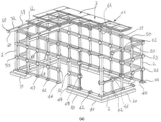
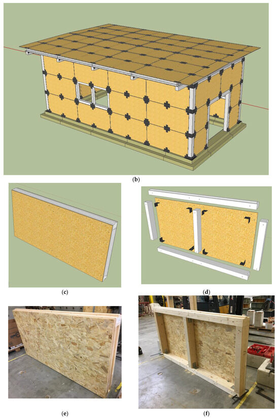
Figure 2.
Scheme of the structural components (a) and example of prototype building make-up with the modular system proposed here (b). External (c), inner (d) 3D-schematic views of a module. External view of a prototype module (e) and view of the internal part of a module (f).
2.4. Description of the Main Elements
The main component of the system is represented by the modular elements with a two-dimensional development (see elements “M” in Figure 3). These elements are made by means of a closed perimeter frame (elements “F” in Figure 3) connected to two panels (elements “P” in Figure 3) that close the two lateral surfaces of the module. The connection between the elements of the frame F is realized by steel L-shaped plate elements positioned at the corners of the frame, fixed to wooden elements by means of steel screws. Then, the connection between the panels P and the perimeter frame F is realized by steel screws or nails. In the case of longer modular elements, there is also an intermediate element for connecting longer profiles. The two-dimensional elements M01, M02, and M03 described here constitute the principal modular elements of the system and at the same time the closures of the building envelope. The perimeter frame F is designed to be made of solid or laminated wood, and the panels are realized with oriented strand board (OSB) sheets. In fact, the main dimensions of the long module M01, equal to about 250 cm × 125 cm, were chosen based on the most popular OSB panels on the European market. The perimeter frames F01 or F02, coupled with the closing panels P01 or P02, create an internal volume that can remain empty or also be filled with particular materials when particular thermal–acoustic levels must be guaranteed. A peculiar aspect of the frame F is represented by the cross-section of the beam elements: they have a main rectangular section 160 × 100 mm2 with a nail of 55 mm in size on one side and a socket of 60 mm in size on the other side (see Figure 3) in order to realize a geometrical joint able to prevent errors and misalignments during the installation phases. The chosen materials for both panels (made by OSB-3) and frames (construction timber) are already certified as construction material, and for fire prevention purposes, they are certified for class D-s2, d0 (according to UNI EN 13501-1), and class 3 (according to UNI 9177).
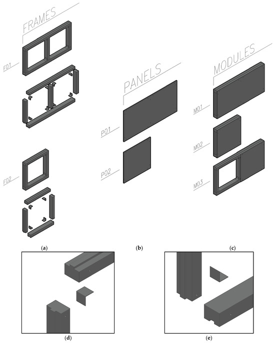
Figure 3.
Main elements of the modular system. (a) perimeter frames “F”, (b) closing lateral panels “P”, and (c) assembled modules “M”. (d,e) Details of cross-section and connection of the main elements of the frames F.
2.5. Description of the Complementary Elements
The complementary elements making up the building are mainly constituted by wooden beam elements that make up the corners of the building, provide a frame for the connection of the fixtures of windows and doors, make up the roof structure, and sustain the modular elements in the roof. The complementary elements are visible in Figure 2, and they are grey in colour. The dimensions of these elements can be standardized on the basis of the dimensions of the modular elements M that represent the key element of the structural system.
2.6. Description of the Foundation Elements
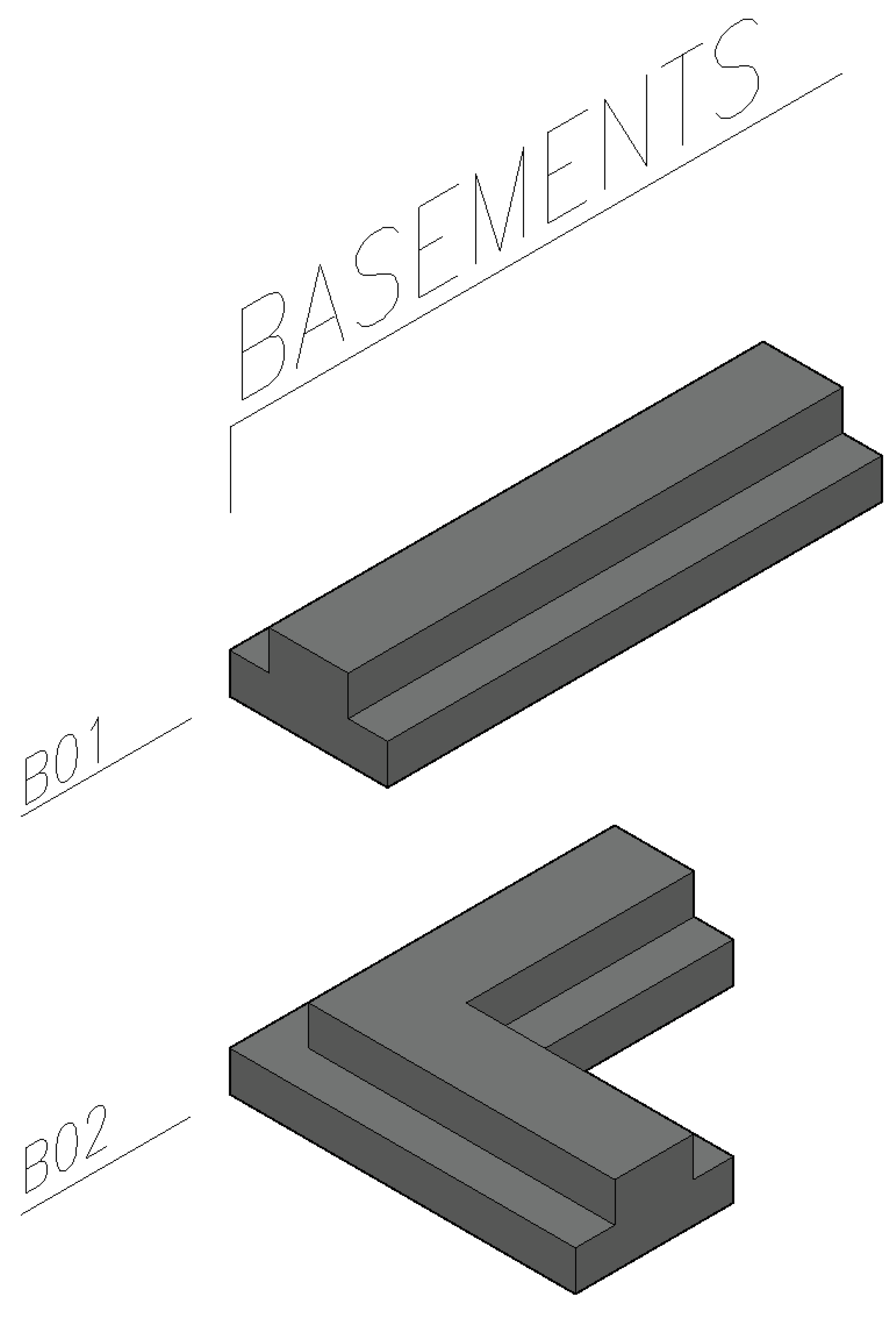
In addition to the above-ground structure, the building system proposed here involves the adoption of precast-reinforced concrete foundation elements, which provide the support to the vertical elements of the wooden structure. The foundation elements have an overturned T cross-section with a typical length that is equal to the main dimension of the modular elements, i.e., 1250 mm or 2500 mm. The main dimensions of the cross-section have been designed with reference to the vertical loads, and the different foundation elements are then connected between them by means of external steel connections. The 3D views of the precast-reinforced concrete basement elements (elements “B”) of the foundation system are showed in Figure 4.
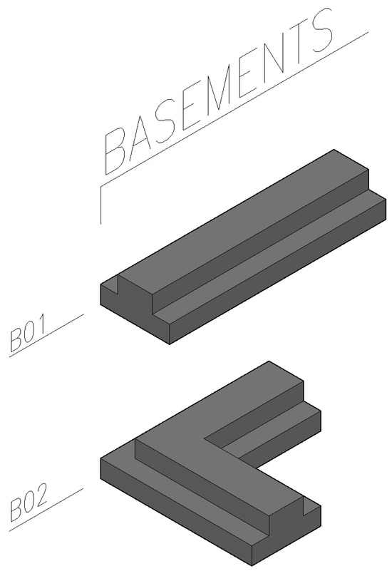
Figure 4.
3D views of the basement elements of the foundation system.
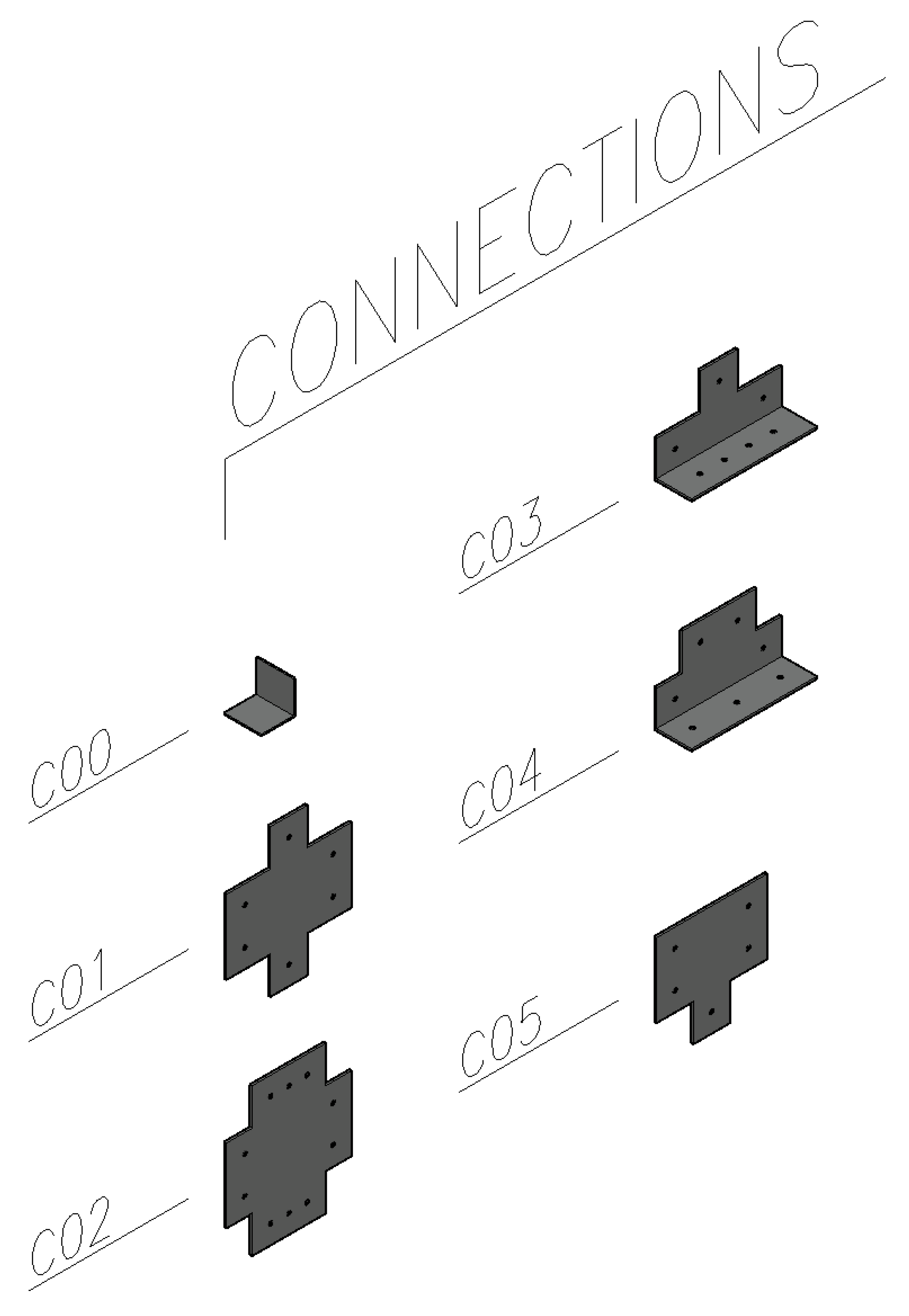
2.7. Description of the Connection System
The connection system between the wooden elements of the structure includes a threaded dowel inserted in a preformed hole in the wooden structure and clamping two steel plates by means of a bolt coupled to a washer (see Figure 5). The connections are then localized at the extremities of the modules and are strongly standardized. This is a particularly effective solution that is able to ensure a quick and easy assembly/disassembly of building components without the risk of damaging the different components after repeated assembly and disassembly operations. In Figure 5, some of the most important connections of the system are shown. Every connection between two or more elements is realized by two external steel plates designed specifically for each specific position and are strongly standardized with a very simple geometry. For example, the connection plate C00 in the figure represents the plates connecting, at the corners, the main elements of the frames F01 and F02; instead, plates C01, C02, and C05 are typical of the connections between modules, and finally, C04 and C03 are plates designed for the connection between vertical modules and basement elements.
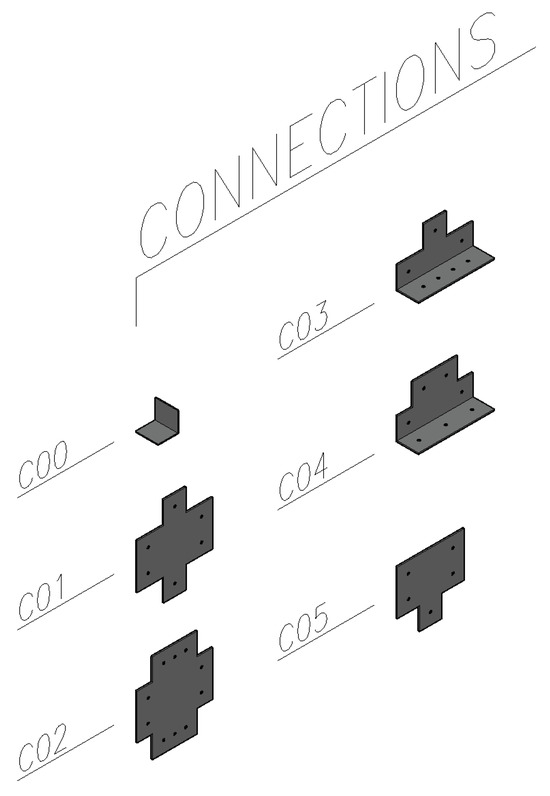
Figure 5.
View of some connection plates of the system.
3. Results and Discussion
3.1. Preliminary Design of a Prototype Building
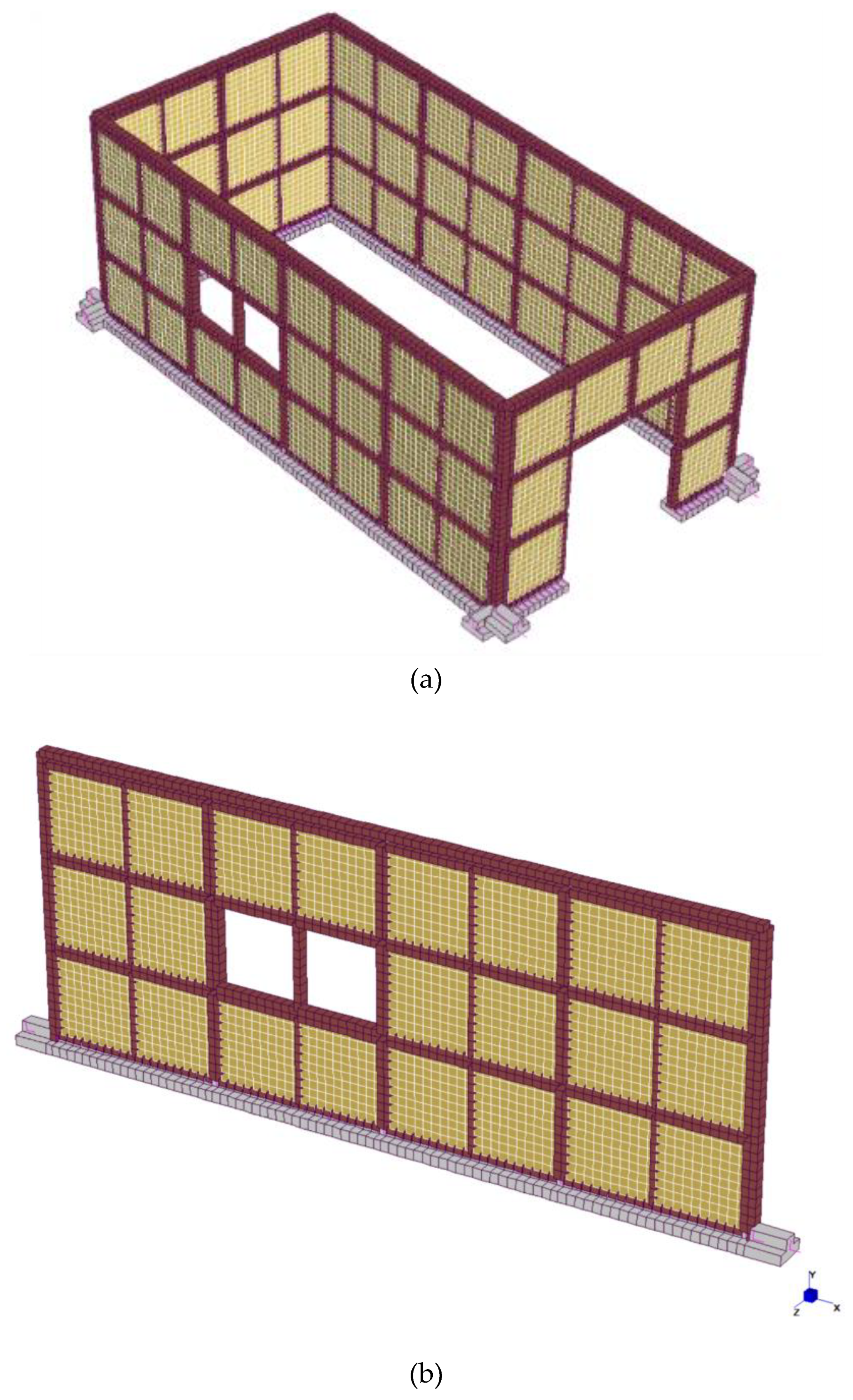
A preliminary design of a prototype building has been conducted to assess the gross sections of the main elements and estimate the key parameters of the structural elements. A 3D structural model was created using the software MIDASGen 2014 (v1.1) (see Figure 6) [24]. To perform the size dimensioning of the wooden modular elements, Eurocode 5 [25] has been considered. The building, shown in Figure 1, has 10 m × 5 m plane dimensions and is 4 m in height. For the analysis and evaluation of the static and dynamic behaviour of the prototype structure, a finite element model was adopted. A global 3D model of the structure was created (see Figure 6); the frame of each wooden module was modelled with classic one-dimensional beam elements with formulated flexibility, and the wooden panels of each module were modelled with two-dimensional finite elements like a four-node Lagrangian shell with membrane and flexural flexibility. The elastic properties assumed for the wooden elements are as follows: Young modulus E = 8000 MPa and Poisson ratio n = 0.1. The precast-reinforced concrete foundation elements have been modelled with one-dimensional beam elements with formulated flexibility and characterized by a Young modulus E = 30,000 MPa and Poisson ratio n = 0.15.
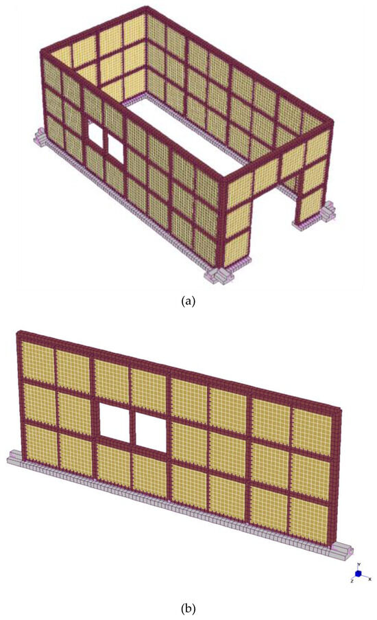
Figure 6.
Views of finite element model of the prototype building investigated. (a) Whole 3D model and (b) lateral side of the model.
For the model, a clamped constraint was considered at the base of the structure, and it was applied to the nodes of the foundation elements. The non-structural dead loads (i.e., the roofing system) and the live loads (i.e., snow load) were entered into the model as vertical forces applied to the roof elements of the building. The structural dead load was automatically calculated from the software. The action of the wind on the structure was determined with horizontal pressure applied on the perimeter panels following the indications of Eurocode 1 [26].
The seismic action, on the other hand, was considered by means of a linear dynamic analysis with a response spectrum; for the building, a rigid floor was assumed, modelled by means of membrane-rigid links positioned at the roof level. The numerical analyses considered are the linear static and the linear dynamic analyses, where the latter was used for the application of the seismic action on the structure. The gross dimensions of the main elements of the structure, as resulting from a pre-design of the building, are reported for the sake of completeness in Table 1.

Table 1.
Class of the materials and main characteristics assumed in the design of the principal elements of the investigated prototype building.
For the assessment of the internal forces on the various elements, in agreement with Eurocode 1, load combinations were considered to maximize bending, shear stresses, as well as axial stresses on the various elements to capture the maximum stress values for the structure. Ultimate Limit States (ULSs) and combinations against Collapse Limit States (CLSs) have been considered for static design and seismic design, respectively.
For the definition of live loads (i.e., snow load and wind load) and seismic actions to consider in the design, the building has been assumed to be located in a geographical area characterized by the following data:
- site location: Emilia Romagna region (Italy) at 300 m above the sea level, in open field and in absence of obstacles;
- soil class for seismic analyses: D;
- seismic characteristics at of the site at CLS: ag = 0.4 g; F0 = 2.4; Tc* = 0.30 s.
Under these hypotheses, the nominal (vertical) distributed snow load to apply at the structure resulted in a value equal to 2 kN/m2, while the nominal (horizontal) distributed wind load resulted in a value equal to 0.7 kN/m2. On the other hand, with reference to seismic analyses, the behaviour factor has been assumed to be equal to 2 following the suggestion of Eurocode 8 [27].
3.2. Preliminary Results Under Static Loads
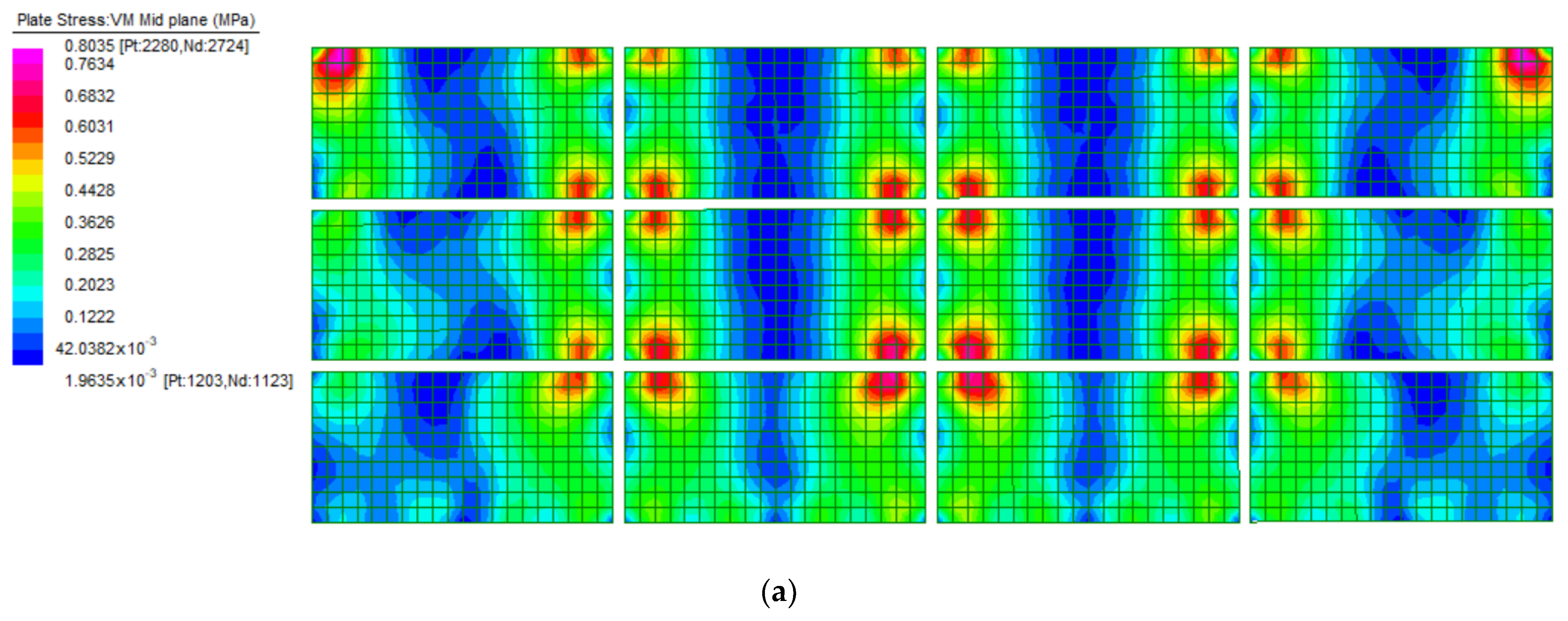
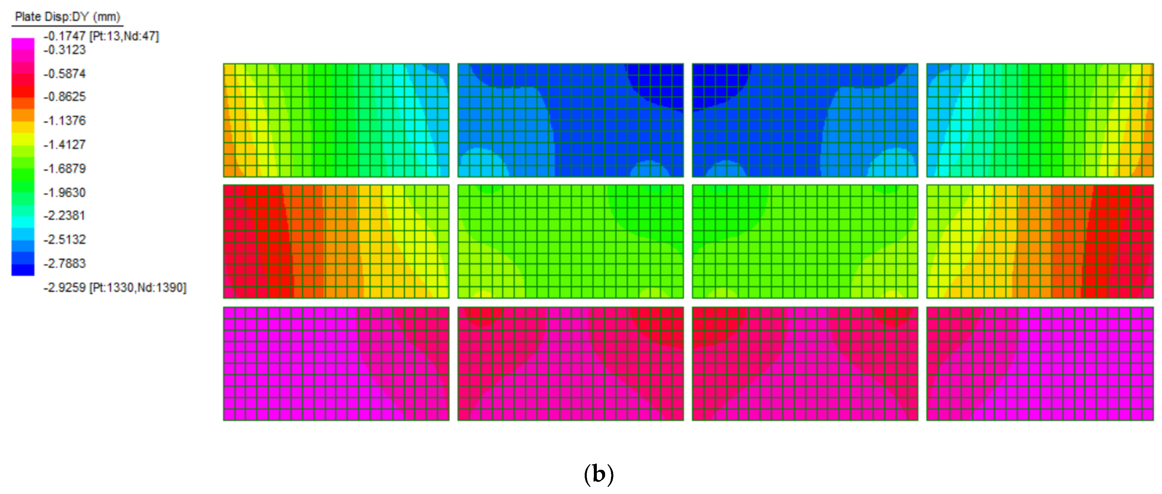
The results extracted from the envelope of the static combinations at the ULS provide the stress contour, shown in Figure 7, for the elements of the different frames. The values reported are compatible with the design strength of the materials selected in the design phase. In the analysis of the vertical displacement values assessed by the model (see Figure 7b), the results show that they are compatible with non-structural elements and systems that can be clamped or anchored on the structure. Similar conclusions can be obtained by the analysis of the results of stress and displacements measured on the OSB panels of the modules (see Figure 8). Even in this case, they are compatible with the capacity of the materials adopted, and as expected, the stress peaks are localized in correspondence with the connections.
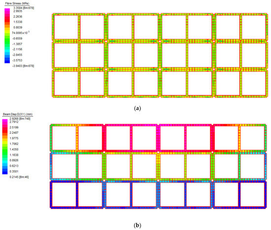
Figure 7.
Contour of (a) normal stress and (b) vertical displacements for the structural elements of the modules.
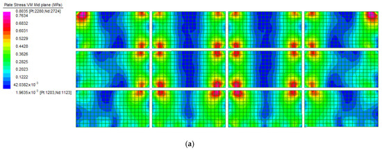
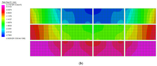
Figure 8.
Contour of (a) normal stress and (b) vertical displacements for the OSB panels of the modules.
3.3. Preliminary Results for Horizontal Actions
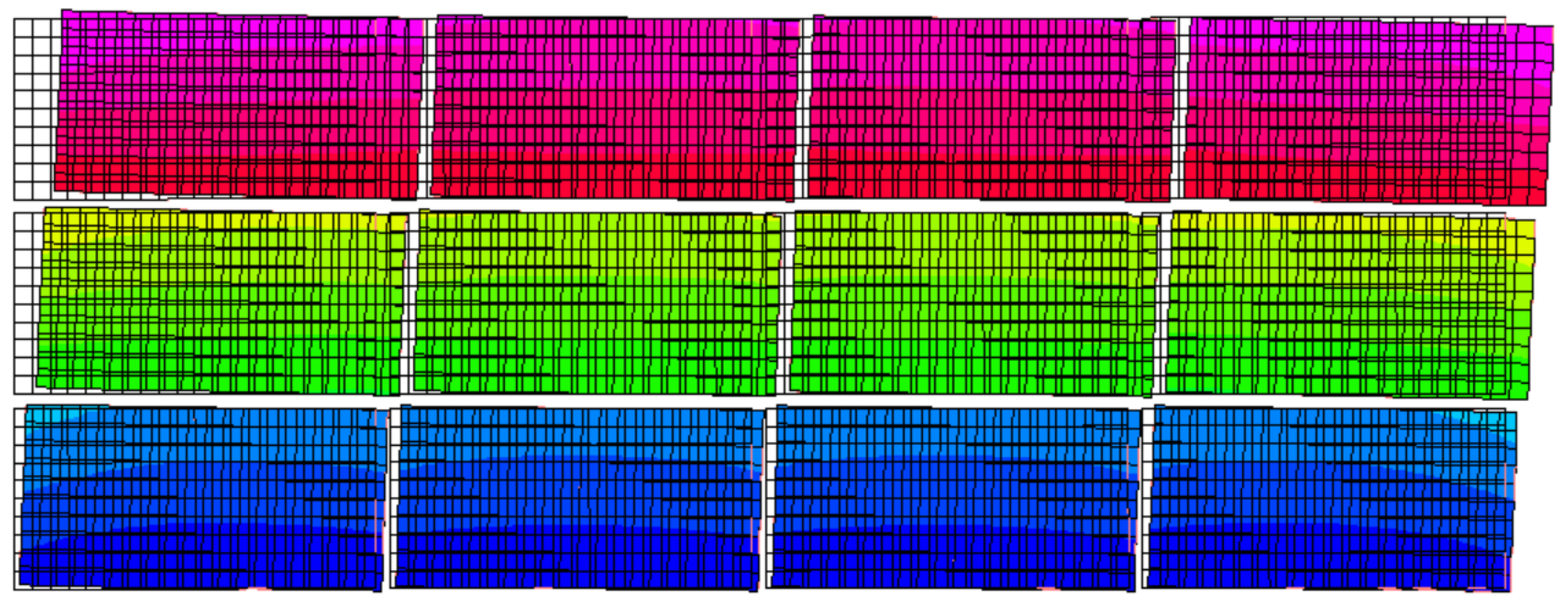
The analysis of the natural frequencies and the associated natural vibration modes suggests that the dynamic behaviour of the system proposed in this paper is similar to the dynamic behaviour of a timber wall system [28]. In fact, the high in-plane stiffness of the modules associated with the low slenderness of the building provides a typical shear-based horizontal deflection. Moreover, because the structure is substantially symmetrical and is characterized by one story, it is sufficient to consider only the first translational mode in each direction to activate a consistent percentage of the vibrating mass of the building. In the present case, the two first modes in the two main orthogonal directions correspond to frequencies of around 4.9 Hz and 5.5 Hz, respectively, and activate more than 90% of the total vibrating mass of the building. Just to provide the evidence of this peculiarity, in Figure 9, the horizontal deflection of the building from a lateral view is shown. This is evident as each horizontal lane of panels deformed and slid relatively with respect to the lane immediately below. The relative horizontal displacements between one panel lane and the lane below, in this shear-type deformed shape, is mainly governed by the membrane stiffness of the connection between the panels.
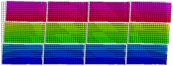
Figure 9.
Modal deformed shape associated with the first vibrating mode for the X direction of the model of the case study building.
Obviously, the structural behaviour of the system can be validated only by means of experimental tests and for this reason, the next step of the development of this technology will be the creation of a full-scale prototype of the structural system and the realization of a series of experimental tests in order to evaluate the real behaviour of the modular system and verify the reliability of the model and the accuracy of the preliminary design. This is out of the scope of the present paper but represents the necessary next step of the work.
3.4. Thermal Performance
As previously explained, the panels are made from a solid part (made by the two OSB panels and the beam) and a hollow part, which represent the majority of the structural panel (see Figure 2). In fact, observing the panel surface, the total area is 3125 m2, while the area occupied by the frame is only 26%, allowing the remaining 2,31 m2 to be filled, varying from systems to insulation materials. For the latter, almost all the most common insulating materials can be suitable to be inserted to return different thermal characteristics. As shown in Table 1, the OSB panels are 22 mm thick, while the frame is 160 mm thick, creating a 160 mm thick hollow part. Therefore, the total thickness of the wall is 204 mm. Additionally, promising results have been found in recent works [29,30], where agricultural byproducts and wastes can be useful if used as thermal and acoustic insulating materials. Under this light, the panels can result in different thermal performances according to the user’s need, with no increase in volume. Table 2 reports the thermal and physics characteristics of some possible solutions using both common materials and more sustainable materials (such as agricultural byproducts), considering 160 mm thick insulation materials (as think as the hollow part) and liminal layers for vertical walls. The last column, average panel transmittance, considers both the frame and insulation portions.
Table 2.
Thermal characteristics of the panel obtained filling the hollow part with different materials.
Calculations have been made using UNI-EN-ISO 11300, material data have been taken from several commercial producers’ data sheets, and corn cob data have been taken from [29]. Specifically, the first two rows report data for the hollow and the frame parts of the panel; the other rows concern the hollow part when filled by the materials reported in the first column.
As visible from Table 2, the hollow panel average transmittance (U) is 1.353 W/m2K. When filled with other materials, the U value varies from 0.522 (corn cob) to 0.235 (polyurethan). These values are close to those required by different national regulations (i.e., 0.22 W/m2K, Italy, Zone E) for residential buildings. Even though the corn cob returns the highest U value, this solution can be very interesting for farmers who deal with corn production, since it is often considered as waste. Further studies will consider experimental tests to define precise values, including the thermal bridges coming from the steel connections. Moreover, the increases in mass are within the additional loads used in the structural calculation. For the results reported in Table 2, only one material is inserted in the panel. Multilayer materials can be specifically produced to improve the characteristics.
3.5. End-of-Life of the Building Components
This system has different viable scenarios, all of them involving several potential processes, depending on local infrastructure, environmental regulations, and final conditions. The wood frames can be recycled by breaking them down into wood fibres, which can be reused to make new panels or other wood-based products, or can be incinerated in waste-to-energy plants to generate heat or electricity. Instead, steel plates and bars, being highly durable and recyclable, have several possible end-of-life (EOL) scenarios. The choice of disposal or reuse methods depends on the material’s condition, local infrastructure, and environmental considerations. Steel can be collected, sorted, and melted in electric arc furnaces or basic oxygen furnaces and recycled steel can be used to manufacture new steel products with little loss in quality. If the steel is not suitable for high-grade applications, it may be downcycled into lower-quality products, such as rebar, pipes, or sheet metal. Steel plates and bars rarely end up in landfills due to their recyclability and value as scrap metal. From a theoretical and preliminary point of view, given the multiplicity of recovery or recycling solutions for this system, it is possible to consider the solution as a low environmental impact structure, especially if compared to the existing one, also considering the fact that it involves limited land consumption and a temporary duration.
4. Conclusions
In this study, the pressing need for adaptable, durable, and sustainable temporary structures in response to the growing demand driven by migration, natural disasters, and seasonal agricultural activities are shown. As conventional building practices have often overlooked durability and last-longing materials, leading to significant environmental impacts, this research introduces a novel type of temporary construction that addresses these challenges.
The structure is based on a wooden panel made by a glulam frame inside two OSB panels that work as a structural bracing, creating a hollow, resistant, and light structure. Panels are connected using specifically designed steel connections. The proposed solution, which has secured a European patent, focuses on maintaining structural integrity and flexibility, allowing for multiple assembly and disassembly cycles throughout its lifespan thanks to specifically designed steel connections.
The main conclusions of the work can be summarized in the following aspects:
- This study shows that on the one hand, this innovative system meets the necessary requirements for temporary agriculture applications, and on the other hand, offers a more sustainable alternative to traditional construction methods.
- Thanks to its hollow structure, the panels can be filled by different materials, allowing for modifications to the thermal characteristic of the panel. In particular, the insertion of agricultural byproducts can influence the expected thermal properties of the building, highlighting its energy efficiency and the possibility to adapt to different contexts, further contributing to its environmental performance.
- In discussing existing solutions, we examined the importance of sustainability in the construction lifecycle, particularly regarding the disposal phase. The proposed system addresses these concerns by extending usability and delaying disposal, thus minimizing waste and reducing the carbon footprint.
- Through structural static and seismic calculations, the design has been proven to ensure safety and reliability in diverse conditions. Further study will consider structural, thermal, and acoustic experimental tests aimed at increasing the TRL of the proposed solution.
- Finally, this innovation presents a viable option for temporary constructions that combine adaptability, environmental sustainability, and long-term usability, making it a promising approach for future developments in both emergency relief and seasonal agricultural sectors.
Future works will focus on the following aspects:
- -
- structural tests to assess the effectiveness of the connections between the frame and OSB panels, and the global seismic response of the panels;
- -
- experimental tests to define thermal transmittance using different bio-based and/or biowaste materials;
- -
- analysis and tests to improve panel fire behaviour (such as increasing thickness, fire retardant, etc.).
Author Contributions
Conceptualization, M.B. and A.B.; methodology, M.B., E.S. and A.B.; software, M.B.; validation, M.B., E.S. and A.B.; formal analysis, E.S.; investigation, E.S. and A.B.; resources, A.B.; data curation, M.B. and A.B.; writing—original draft preparation, M.B., E.S. and A.B.; writing—review and editing, M.B., E.S. and A.B.; visualization, A.B.; supervision, A.B.; project administration, E.S.; funding acquisition, A.B. All authors have read and agreed to the published version of the manuscript.
Funding
This research received no external funding.
Data Availability Statement
Data will be provided under request.
Conflicts of Interest
The authors declare no conflict of interest.
References
- Tang, S.; Yao, Y.; Andrade, C.; Li, Z.J. Recent durability studies on concrete structure. Cem. Concr. Res. 2015, 78, 143–154. [Google Scholar] [CrossRef]
- Eberhardt, L.C.M.; Birkved, M.; Birgisdottir, H. Building design and construction strategies for a circular economy. Arch. Eng. Des. Manag. 2022, 18, 93–113. [Google Scholar] [CrossRef]
- Torres, V.; Íñiguez-González, G.; Blanchet, P.; Giorgio, B. Challenges in the Design for Disassembly of Light Timber Framing Panelized Components. Buildings 2025, 15, 321. [Google Scholar] [CrossRef]
- Seeberg, H.R.; Haakonsen, S.M.; Luczkowski, M. Systematic Mapping of Circular Economy in Structural Engineering. Buildings 2024, 14, 1165. [Google Scholar] [CrossRef]
- Geissdoerfer, M.; Savaget, P.; Bocken, N.M.P.; Hultink, E.J. The Circular Economy—A new sustainability paradigm? J. Clean. Prod. 2017, 143, 757–768. [Google Scholar] [CrossRef]
- Winans, K.; Kendall, A.; Deng, H. The history and current applications of the circular economy concept. Renew. Sustain. Energy Rev. 2017, 68, 825–833. [Google Scholar] [CrossRef]
- Ghobadi, M.; Sepasgozar, S.M.E. Circular economy strategies in modern timber construction as a potential response to climate change. J. Build. Eng. 2023, 77, 107229. [Google Scholar] [CrossRef]
- Ghobadi, M.; Sepasgozar, S.M.E. Design for reuse in prefabricated timber buildings: Simultaneous evaluation of criteria and alternatives and TOPSIS analyses. J. Build. Eng. 2025, 103, 112174. [Google Scholar] [CrossRef]
- Ostapska, K.; Rüther, P.; Loli, A.; Gradeci, K. Design for Disassembly: A systematic scoping review and analysis of built structures Designed for Disassembly. Sustain. Prod. Consum. 2024, 48, 377–395. [Google Scholar] [CrossRef]
- Di Ruocco, G.; Melella, R.; Sabatano, L. Timber Buildings Deconstruction as a Design Solution toward Near Zero CO2e Emissions. Buildings 2023, 13, 157. [Google Scholar] [CrossRef]
- Ottenhaus, L.M.; Yan, Z.; Brandner, R.; Leardini, P.; Fink, G.; Jockwer, R. Design for adaptability, disassembly and reuse—A review of reversible timber connection systems. Constr. Build. Mater. 2023, 400, 132823. [Google Scholar] [CrossRef]
- Gutiérrez, N.; Negrão, J.; Dias, A.; Guindos, P. Bibliometric Review of Prefabricated and Modular Timber Construction from 1990 to 2023: Evolution, Trends, and Current Challenges. Sustainability 2024, 16, 2134. [Google Scholar] [CrossRef]
- European Commission. EPBD-Recast of the Directive on the Energy Performance of Buildings (2010/31/EU); European Commission: Brussels, Belgium, 14 December 2010. [Google Scholar]
- Cristóbal, J.; Foster, G.; Caro, D.; Yunta, F.; Manfredi, S.; Tonini, D. Management of excavated soil and dredging spoil waste from construction and demolition within the EU: Practices, impacts and perspectives. Sci. Total Environ. 2024, 944, 173859. [Google Scholar] [CrossRef]
- Ilgın, H.E.; Karjalainen, M.; Pelsmakers, S. Contemporary Tall Residential Timber Buildings: What are the Main Architectural and Structural Design Considerations? Int. J. Build. Pathol. Adapt. 2022, 41, 26–46. Available online: https://www.emerald.com/insight/content/doi/10.1108/ijbpa-10-2021-0142/full/html (accessed on 1 December 2024).
- Lisco, M.; Aulin, R. Taxonomy Supporting Design Strategies for Reuse of Building Parts in Timber-Based Construction, Constr. Innov., 2024, 24, 221–241. Available online: https://www.emerald.com/insight/content/doi/10.1108/ci-11-2022-0293/full/html (accessed on 1 December 2024).
- Tenório, M.; Ferreira, R.; Belafonte, V.; Sousa, F.; Meireis, C.; Fontes, M.; Vale, I.; Gomes, A.; Alves, R.; Silva, S.M.; et al. Contemporary Strategies for the Structural Design of Multi-Story Modular Timber Buildings: A Comprehensive Review. Appl. Sci. 2024, 14, 3194. [Google Scholar] [CrossRef]
- Barbaresi, A.; Bovo, M.; Torreggiani, D.; Tassinari, P. Modular Building. European Patent 102019000011301, 2021. Available online: https://it.espacenet.com/publicationDetails/biblio?II=1&ND=3&adjacent=true&locale=it_IT&FT=D&date=20210109&CC=IT&NR=201900011301A1&KC=A1dal09-07-2019aoggi (accessed on 1 December 2024).
- Italian Ministry of Public Works. Testo Unico Dell’Edilizia 2001; Italian Ministry of Public Works: Rome, Italy, 2001. [Google Scholar]
- Collins English Dictionary 2023; HarperCollins: New York, NY, USA, 2023.
- David, M.N.; Miguel, R.S.; Ignacio, P.Z. Timber structures designed for disassembly: A cornerstone for sustainability in 21st century construction. J. Build. Eng. 2024, 96, 110619. [Google Scholar] [CrossRef]
- Dams, B.; Maskell, D.; Shea, A.; Allen, S.; Driesser, M.; Kretschmann, T.; Walker, P.; Emmitt, S. A circular construction evaluation framework to promote designing for disassembly and adaptability. J. Clean. Prod. 2021, 316, 128122. [Google Scholar] [CrossRef]
- Kayaçetin, N.C.; Verdoodt, S.; Lefevre, L.; Versele, A. Integrated decision support for embodied impact assessment of circular and bio-based building components. J. Build. Eng. 2023, 63, 105427. [Google Scholar] [CrossRef]
- Midas GEN. Analisi e Progettazione Strutturale-CSPFea n.d. Available online: https://www.cspfea.net/prodotti/midas-gen/ (accessed on 25 March 2025).
- EN 1995-1-1; 2004 Eurocode 5: Design of Timber Structures—Part 1–1: General-Common Rules and Rules for Buildings. CEN: Brussels, Belgium, 2004.
- EN 1991-1-4; 2005 Eurocode 1: Actions on Structures—Part 1–4: General Actions-Wind Actions. CEN: Brussels, Belgium, 2010.
- Pozza, L. Ductility and Behaviour Factor of Wood Structural Systems. Theoretical and Experimental Development of a High Ductility Wood-Concrete Shearwall System. Ph.D. Thesis, University of Padua, Padova, Italy, 2013. [Google Scholar]
- Premrov, M.; Žegarac Leskovar, V. Structural Systems of Timber Buildings. In Energy-Efficient Timber-Glass Houses; Springer: London, UK, 2013; pp. 53–116. [Google Scholar] [CrossRef]
- Bovo, M.; Giani, N.; Barbaresi, A.; Mazzocchetti, L.; Barbaresi, L.; Giorgini, L.; Torreggiani, D.; Tassinari, P. Contribution to thermal and acoustic characterization of corn cob for bio-based building insulation applications. Energy Build. 2022, 262, 111994. [Google Scholar] [CrossRef]
- Barbaresi, A.; Bovo, M.; Santolini, E.; Barbaresi, L.; Torreggiani, D.; Tassinari, P. Development of a low-cost movable hot box for a preliminary definition of the thermal conductance of building envelopes. Build. Environ. 2020, 180, 107034. [Google Scholar] [CrossRef]


Disclaimer/Publisher’s Note: The statements, opinions and data contained in all publications are solely those of the individual author(s) and contributor(s) and not of MDPI and/or the editor(s). MDPI and/or the editor(s) disclaim responsibility for any injury to people or property resulting from any ideas, methods, instructions or products referred to in the content. |
© 2025 by the authors. Licensee MDPI, Basel, Switzerland. This article is an open access article distributed under the terms and conditions of the Creative Commons Attribution (CC BY) license (https://creativecommons.org/licenses/by/4.0/).