Article

Experimental Study of Pre-Tensioned Polygonal Prestressed T-Beam Under Combined Loading Condition

1
State Key Laboratory of Coastal and Offshore Engineering, Dalian University of Technology, Dalian 116024, China
2
Shanghai Municipal Engineering Design Institute (Group) Co., Ltd., Shanghai 200092, China
3
Jiangxi Gan Yue Expressway Co., Ltd., Nanchang 330025, China
4
Jiangxi Communications Investment Group Co., Ltd., Nanchang 330108, China
5
Jiangxi Communications Design and Research Institute Co., Ltd., Nanchang 330029, China
*
Author to whom correspondence should be addressed.
Buildings 2025, 15(8), 1379; https://doi.org/10.3390/buildings15081379
Submission received: 24 March 2025 / Revised: 14 April 2025 / Accepted: 17 April 2025 / Published: 21 April 2025
(This article belongs to the Special Issue Structural Vibration Analysis and Control in Civil Engineering)

Abstract

:
In order to investigate the mechanical behavior of a novel pre-tensioned polygonal prestressed T-beam subject to combined bending, shear, and torsion, this study meticulously designed and fabricated a full-scale specimen with a calculated span of 28.28 m, a beam height of 1.8 m, and a top flange width of 1.75 m. A systematic static loading test was conducted. A multi-source data acquisition methodology was employed throughout the experiment. A variety of embedded and external sensors were strategically arranged, in conjunction with non-contact digital image correlation (VIC-3D) technology, to thoroughly monitor and analyze key mechanical performance indicators, including deformation capacity, strain distribution characteristics, cracking resistance, and crack propagation behavior. This study provides valuable insights into the damage evolution process of novel polygonal pre-tensioned T-beams under complex loading conditions. The experimental results indicate that the loading process of the specimen when subjected to combined bending, shear, and torsion, can be divided into two distinct stages: the elastic stage and the crack development stage. Cracks initially manifested at the junction of the upper flange and web at the extremities of the beam and at the bottom flange of the loaded segment. Subsequently, numerous diagonal and flexural–shear cracks developed within the web, while diagonal cracks also commenced to form on the top surface, exhibiting a propensity to propagate toward the support section. Following the appearance of diagonal cracks in the web concrete, both stirrup strain and concrete strain demonstrated abrupt changes. The peak strain observed within the upper stirrups was markedly greater than that measured in the middle and lower regions. On the front elevation of the web, the principal strain peak was concentrated near the connection line between the loading bottom and the upper support. In contrast, on the back elevation of the web, the principal tensile strain was more pronounced near the connection line between the loading top and the lower support.

1. Introduction

With the widespread application of prefabricated prestressed structures in bridge engineering, China has developed a relatively complete prestressing technology system [1,2]. In the domain of small- to medium-span prestressed beams, pre-tensioning and post-tensioning are the two predominant methods for prestress application. Although post-tensioning remains dominant in engineering practice due to its process adaptability, it suffers from inherent technical drawbacks, including difficulties in grout quality control, risks of duct blockage, and insufficient grout compaction. These issues pose significant durability concerns and threaten the long-term performance of structures [3]. In contrast, pre-tensioning applies to prestress directly during the prefabrication stage, effectively avoiding complex procedures such as hole reservation, strand threading, and grouting. This not only simplifies the construction process but also reduces material consumption like corrugated ducts and anchors, fundamentally addressing the durability challenges inherent in post-tensioning systems [4]. Moreover, it aligns well with the industrialization and standardization trends in modern bridge engineering.
Pre-tensioned prestressed beams can be classified into two main configurations based on the arrangement of prestressing strands: straight and polygonal (harped) profiles. While straight pre-tensioned prestressed beams offer construction simplicity, they exhibit unfavorable force distribution in long-span structures, making them less suitable for complex engineering applications. To address these limitations, engineers have introduced strands restraining devices to achieve a polygonal tendon layout in pre-tensioned strands [5,6]. This approach enhances the shear capacity at the beam ends while reducing local stresses, thereby mitigating the risk of cracking in the anchorage zones. Given these advantages, pre-tensioned polygonal prestressed beams have demonstrated significant potential for engineering applications [7,8]. Therefore, investigating their mechanical behavior is crucial for ensuring bridge traffic safety and advancing the theoretical framework of prestressed beam design.
Numerous scholars have researched the mechanical behavior of prestressed beams [9,10,11], primarily focusing on their performance under single loading conditions. For example, Ju et al. [12]. proposed a torsional strength model for prestressed concrete beams and validated its accuracy through experimental studies. Al-Salim et al. [13] conducted combined bending and torsion tests on fiber-reinforced concrete (FRC) beams to investigate the influence of different fiber types. Their findings provide a reference for evaluating the torsional performance of FRC beams under combined loading conditions. Zhang et al. [14] performed four-point bending tests on FRP-reinforced concrete T-beams and proposed a modified shear capacity calculation formula. Jiang et al. [15] investigated the flexural and shear capacities of decommissioned T-beams. The results indicated that despite initial defects, the decommissioned T-beams retained a high safety margin. Zhu et al. [16] conducted flexural performance tests on prestressed high-performance concrete beams and proposed a predictive formula for the flexural capacity of prestressed ultra-high-performance concrete (UHPC) beams, providing a basis for structural design and optimization. Liu Zhao et al. [17] validated the stiffness, crack resistance, and load-bearing capacity of a 30 m pre-tensioned prestressed double-T beam through a four-point bending test. Liu YC [18] systematically revealed the mechanical response of a single-polygonal T-beam at different stages, including serviceability, cracking, and failure, using a stepwise loading method. He also proposed, for the first time, a shear strength calculation formula for this configuration. Yang HY et al. [19] investigated the flexural performance of a 30 m pre-tensioned polygonal beam using finite element analysis and experimental testing. Their results indicated that the beam met design requirements in terms of strength, stiffness, and crack resistance. Hu Ke et al. [20] proposed the wedge theory, which considers the influence of concrete, longitudinal reinforcement, vertical reinforcement, inclined reinforcement, and prestressing tendons on the shear performance of beams. Garber D B et al. [21] conducted experimental studies on the shear performance of pre-tensioned beams. The results indicated that an excessively thin web might induce a non-traditional shear failure mechanism in prestressed beams, leading to a reduction in load-carrying capacity compared to conventional shear failure modes. DEIFALLA et al. [22,23] studied the mechanical behavior of inverted-T reinforced concrete beams and T-section foamed concrete beams under combined shear and torsion, proposing a mechanical performance analysis model for T-sections subjected to shear–torsion interaction.
In summary, existing studies on pre-tensioned polygonal prestressed T-beams primarily focus on their flexural or shear performance. However, during service, these beams inevitably experience significant bending–shear–torsion interactions at their ends due to eccentric loading, temperature variations, and other factors. Moreover, polygonal prestressed strands at the beam ends result in a complex stress state, making shear–torsion performance evaluation particularly challenging. Therefore, an in-depth investigation into the behavior of such T-beams under combined bending, shear, and torsion is necessary.
To investigate the mechanical behavior of pre-tensioned polygonal prestressed T-beams under combined bending, shear, and torsion, this study designs a 30 m-span pre-tensioned polygonal prestressed T-beam and conducts a full-scale experimental investigation. This study focuses on its crack resistance, crack development patterns, and deformation characteristics under these complex loading conditions, providing valuable insights for optimized design and broader engineering applications.

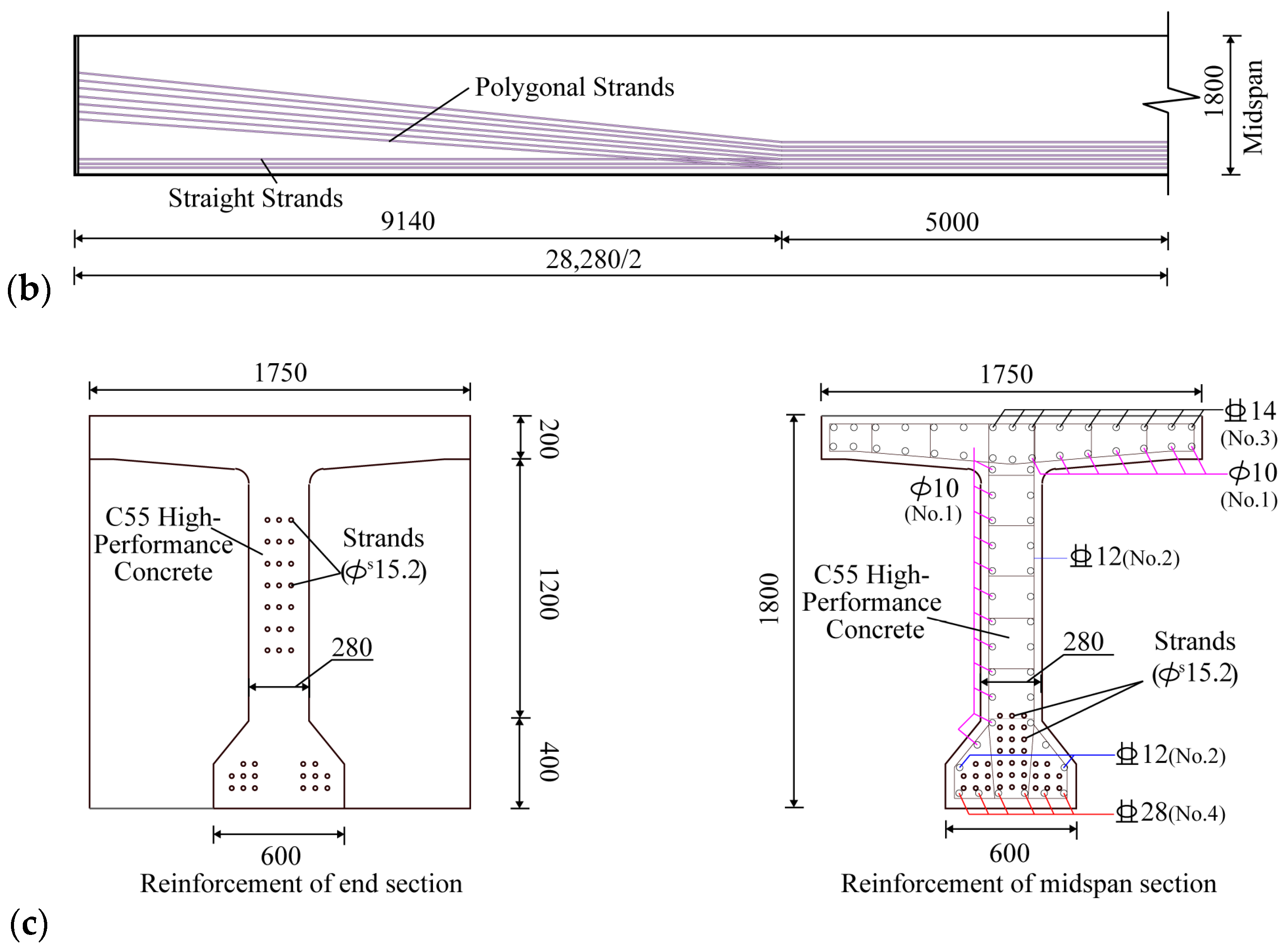
2. Full-Scale Model Parameters of Pre-Tensioned Prestressed T-Beams

In the Changzhang Expressway reconstruction and expansion project, a novel 30 m-span pre-tensioned polygonal prestressed T-beam was designed. The beam has a total length of 30,000 mm, a computed span of 28,280 mm, a section height of 1800 mm, a top flange width of 1750 mm, and a web thickness of 280 mm. The main structure is cast using C55 high-performance self-compacting concrete, while the reinforcement system consists of HRB400-grade stirrups and longitudinal tensile reinforcement. The prestressing system consists of 1 mm × 7–15.2 mm, 1860 MPa-grade low-relaxation strands, forming a hybrid prestressing reinforcement configuration. It includes 16 straight prestressed strands with a tensioning control stress of 0.75 fptk (1395 MPa) and 21 polygonal prestressed strands with a tensioning control stress of 0.72 fptk (1340 MPa). The polygonal prestressed strands are bent using specialized redirectors located 5000 mm from both sides of the midspan section, with an average bending angle of 4.4°. The beam adopts an open-web cross-section, with the conventional diaphragms in the midspan region removed, while end diaphragms are retained to ensure reliable boundary conditions. Detailed geometric parameters, structural configurations, and reinforcement schemes are provided in Figure 1.
The test beam was prefabricated on a long-line pre-tensioning bed using a custom-designed fully automated hydraulic steel formwork. After concrete casting, the beam was left to rest for six hours before undergoing high-temperature steam curing.
Following the GB/T 50081-2019 Standard for Test Methods of Physical and Mechanical Properties of Concrete [24], the compressive strength test was conducted on three concrete cube specimens after 28 days of curing, yielding an average compressive strength of 64.8 MPa. Additionally, tensile tests were performed on the reinforcing steel bars and prestressing strands used in this study according to GB/T 228.1-2021 Metallic Materials—Tensile Testing Methods [25]. The measured results are presented in Table 1.

3. Full-Scale Experimental Scheme

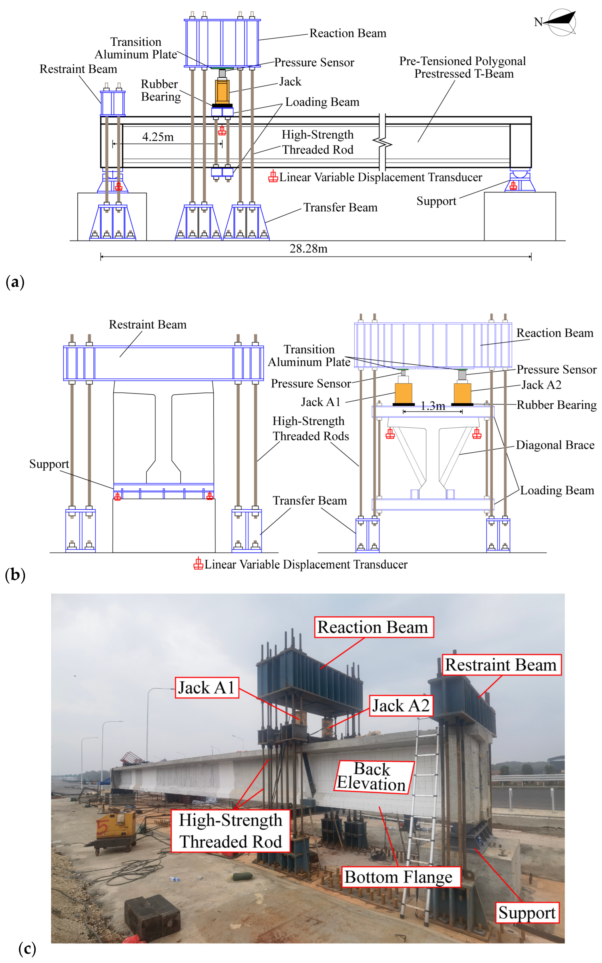
3.1. Loading Device and Loading Scheme

To simulate the actual stress state of a pre-tensioned polygonal prestressed T-beam under combined bending, shear, and torsion, a specialized test setup was designed and fabricated, as shown in Figure 2. In this setup, one end of the specimen was fixed to the test pedestal using high-strength threaded steel bars and a restraining beam system, while loading was applied through a system comprising high-strength threaded steel bars, a transfer beam, and a reaction beam. To ensure loading safety and maintain a consistent load direction, transition aluminum plates were placed between the sensors and the reaction beam, while rubber bearings were placed between the hydraulic jacks and the loading beam. The loading system utilized dual hydraulic jacks, which worked in coordination to achieve a coupled effect of bending moment (M), shear force (V), and torsional moment (T). In this experiment, the shear/span ratio was set to 2.5, and the torsion-to-shear ratio was 0.65.
In this experiment, a two-stage progressive loading strategy was adopted. In the first stage, both hydraulic jacks applied a synchronized load of 127 kN, simulating the effects of self-weight and secondary dead loads. In the second stage, an asymmetric loading mode was employed: jack A2 maintained a constant load, while jack A1 applied incrementally stepped loads—approximately 155 kN per step before cracking and 100 kN per step after cracking. This setup aimed to investigate the nonlinear mechanical response during the crack evolution process in concrete. Loading continued until the displacement at the loading end approached the full-scale range, at which point the test was terminated and unloading was performed. All loading processes were controlled using high-precision pressure sensors, with each load level maintained for 5–7 min to ensure quasi-static conditions. However, before formal loading, a preloading torque equal to 30% of the calculated cracking torque was applied to verify the proper functioning of the data acquisition system. The full-scale model test loading conditions for pre-tensioned polygonal prestressed T-beam are summarized in Table 2.

3.2. Sensor Arrangement Scheme

The test beam was placed in the north–south orientation, with internal force and crack monitoring conducted on its western elevation, as shown in Figure 2a, while VIC-3D was used on the eastern elevation to monitor the strain field of the web. This experiment primarily aimed to investigate the strain distribution, crack development patterns, overall deformation characteristics, and loading conditions of the T-beam under the combined bending, shear, and torsion. Therefore, pressure sensors were installed at the loading sections (one on each hydraulic jack, totaling two), along with displacement sensors (one at each end, totaling two), as illustrated in Figure 2b, to measure the applied torque and the torsional angle at the loading position. The specifications of the hydraulic jacks are provided in Table 3. Linear variable displacement transducers were placed at both support locations (two per end, totaling four, as shown in Figure 2b) to measure support settlements and torsional angles. Strain gauges were installed on the stirrups along the loading-support connection line and across the section height. Strain rosettes were placed on the web along the loading-support connection line to capture the strain distribution of the concrete throughout the loading process. The specimen surface was painted white and marked with a 15 cm square grid to facilitate crack propagation observation. A handheld crack width gauge and a marker were used to measure and record crack widths and locations. Since the strain gauges on stirrup reinforcements were embedded within the concrete, all embedded strain gauges were coated with epoxy resin to ensure proper functionality in the humid environment.

4. Analysis of Experimental Results

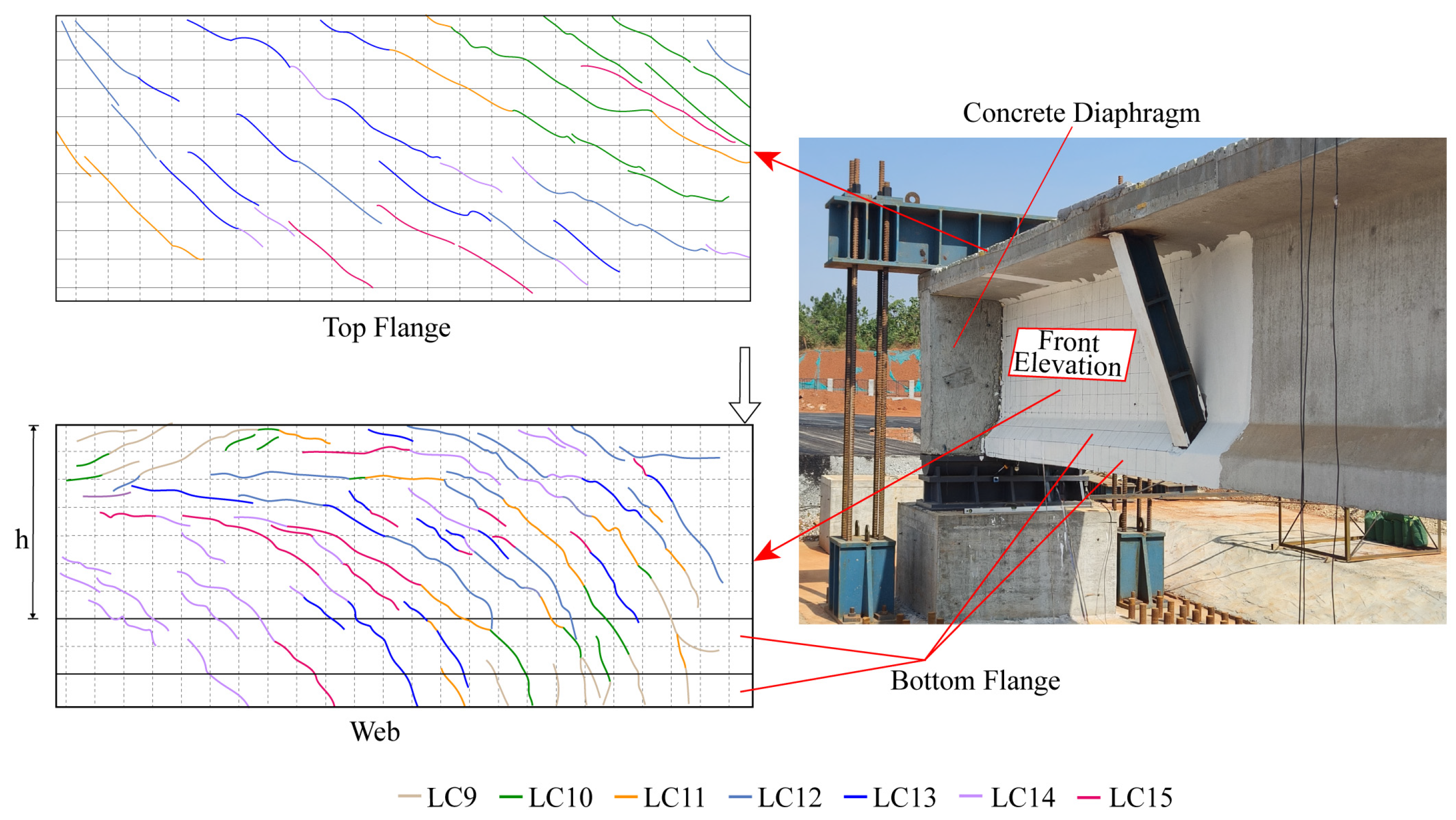
4.1. Experimental Observations

The loading process of the 30 m pre-tensioned polygonal prestressed T-beam is described as follows: During the initial loading stages (LC1–LC8), no visible cracks were observed at any location on the beam, indicating that the structure remained in the elastic phase. When the load increased to LC9, initial diagonal cracks formed at the junction of the top flange and the web due to stress concentration. Meanwhile, vertical flexural–shear cracks formed near the bottom flange of the loading section due to the combined effect of bending and shear, which then gradually propagated diagonally. As the load increased to LC10, the initial cracks propagated along the principal tensile stress direction, reaching the transverse diaphragm. The flexural–shear cracks propagated along the bottom flange into the web, reaching a height of h/4, where h is the web height (as shown in Figure 3), and cracks also began to appear on the top surface. By LC14, multiple diagonal and flexural–shear cracks had developed on the front elevation of the specimen. The initial flexural–shear cracks extended further into the web, reaching approximately 3h/4 in height, with crack widths increasing progressively with the applied load. Eventually, the diagonal and flexural–shear cracks continued to develop, forming cracks with horizontal segments that gradually extended toward the support section. The final crack distribution and crack development process in the test region beam is shown in Figure 3.

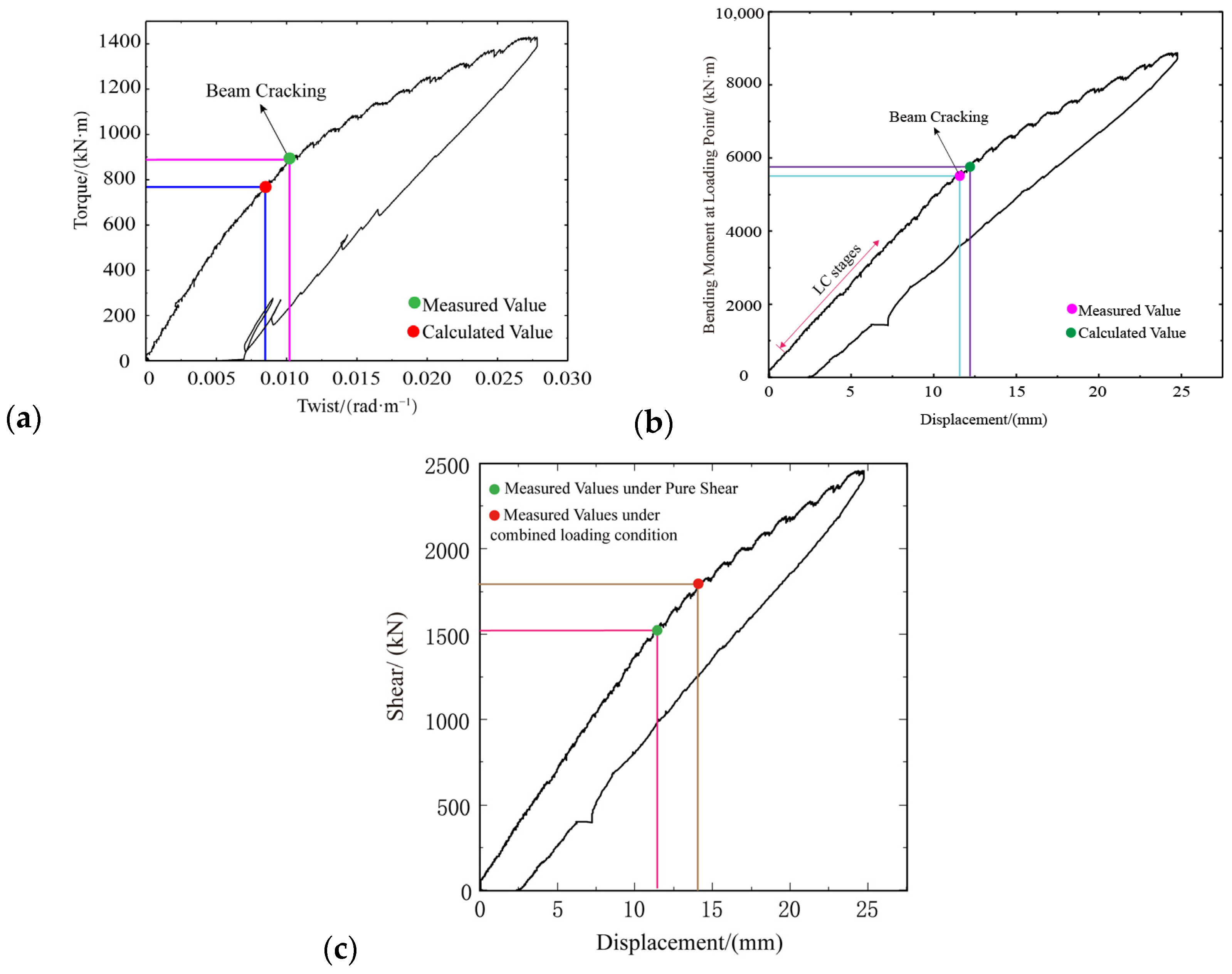
4.2. Torque-Twist Ratio Relationships

The torque/twist ratio curve of the test beam is shown in Figure 4a. The entire testing process can be divided into three stages: the elastic stage, the cracking stage, and the unloading stage. In the initial loading stage, the torque and torsional deformation were relatively small, and the torque/twist ratio relationship exhibited linear behavior. At this stage, no cracks were observed on the specimen surface, indicating that the specimen remained in the elastic stage. When the applied load reached a critical level (torque of approximately 900 kN·m, bending moment of 5491 kN·m, and shear force of 1520 kN), an inflection point appeared in the curve. Cracks formed at the bottom of the loaded section and the upper portion of the web at the beam ends, with a corresponding twist rate of 0.011 rad·m−1. During the cracking stage, the number of diagonal cracks increased, and flexural–shear cracks propagated rapidly, resulting in a reduced curve slope. When the displacement at the loading end approached the full range of 50 mm (corresponding to a twist ratio of approximately 0.028 rad·m−1), unloading commenced. After unloading, the prestress restored most of the vertical displacement, leaving a residual displacement of only 6.5 mm.
Based on the cracking torque calculation formula for prestressed concrete torsional members in ACI 318-19 Building Code Requirements for Structural Concrete [26], the cracking torque of the T-beam under combined bending–shear–torsion was calculated and analyzed. The formula is given as follows:
T cr = ϕ λ f c A c p 2 p c p 1 + f p c 4 λ f c
f c = 0.79 f c u
where Tcr is the calculated cracking torque; ϕ is the strength reduction factor, taken as 0.75; λ is the reduction factor for lightweight concrete, taken as 1.0; fc is the compressive strength of the concrete cylinder; Acp is the cross-sectional area enclosed by the perimeter of the concrete section; Pcp is the perimeter of the concrete section; fpc is the effective precompression stress induced by prestress; and fcu is the compressive strength of the concrete cube.
Based on the above formula, the calculated cracking torque of the test beam is 777 kN·m, while the experimentally measured value is approximately 900 kN·m, as shown in Figure 4. The ratio between the two is 1.16, indicating that the beam exhibits a good cracking resistance reserve. Furthermore, the current code-based calculation methods provide a useful reference for the crack resistance design of beams subjected to combined bending, shear, and torsion.
Figure 4b illustrates the moment–deflection curve at the loaded section of the test beam. Under the combined action of bending, shear, and torsion, the moment at cracking was 5491 kN·m. In contrast, the theoretical cracking moment under pure bending, calculated according to the relevant design code [27], was 5853.5 kN·m, indicating a 7.3% reduction. Figure 4c shows the shear force–displacement curve at the same section. The measured shear force at cracking under combined bending–shear–torsion loading was 1510 kN, while the theoretical cracking shear force under pure shear was 1766 kN, representing a 14.5% decrease. In summary, the combined loading conditions significantly reduced the cracking resistance of the structure.

4.3. Strain Analysis

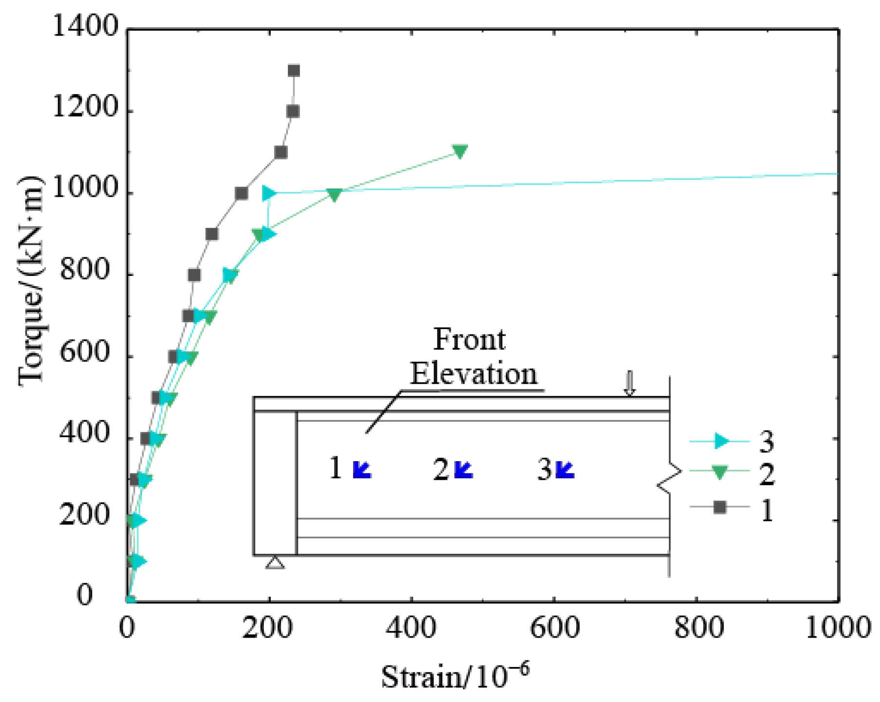
4.3.1. Principal Strain of Concrete

The principal strain at the measurement points on the web surface of the test beam is shown in Figure 5. During the initial loading stage, the principal strain exhibits minimal variation and generally increases linearly. After the appearance of diagonal cracks, the strain curve at the measurement points undergoes an inflection, with an accelerated growth rate. Measurement point 1, located near the support, initially experiences a rapid increase in strain, which then stabilizes, indicating that the crack near this point does not continue to propagate. Measurement point 3, positioned in the upper-middle part near the loading section, exhibits strain growth only during loading due to the extension of diagonal cracks. Measurement point 2, located in the middle of the web, shows the highest strain growth rate and the largest strain magnitude, suggesting that this measurement point is likely situated near the primary crack.

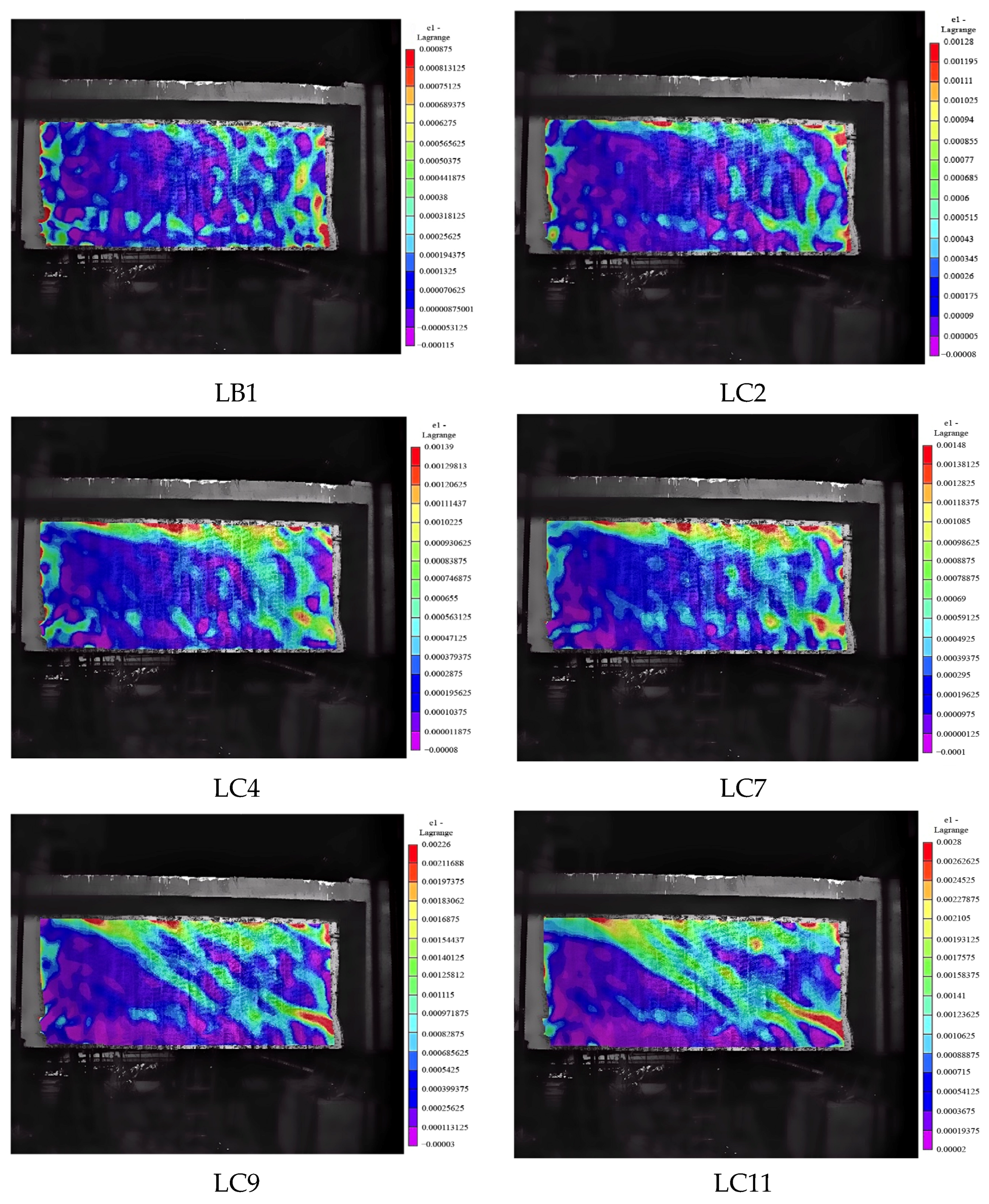
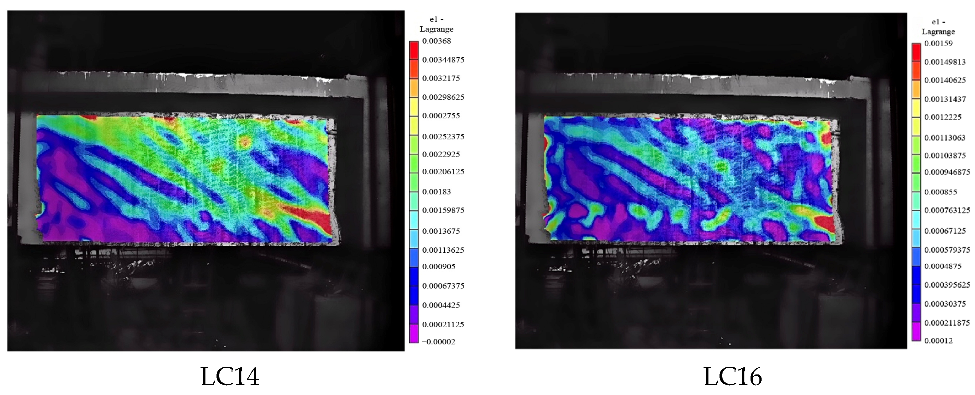
4.3.2. Strain Field Analysis of the Beam Based on VIC-3D

The full-field strain distribution of the concrete on the back elevation of the web, as shown in Figure 2c, was obtained from VIC-3D image analysis. Figure 6 presents the principal tensile strain distribution of the test beam under different loading conditions. In the early loading stages (before LC2), strain concentration was observed in the upper part of the specimen, resulting in localized strain increases; however, the overall variation remained minimal. As the test progressed to LC9, the strain in the upper web of the specimen increased rapidly due to the applied torque, while the strain on the back surface continued to rise as diagonal cracks formed. With further load increments (beyond LC9), localized strain on the back surface of the specimen increased significantly, diagonal cracks propagated rapidly, and the principal strain in the concrete also escalated. During the unloading stage (LC16), residual strain remained in localized regions of the back surface due to cracking.

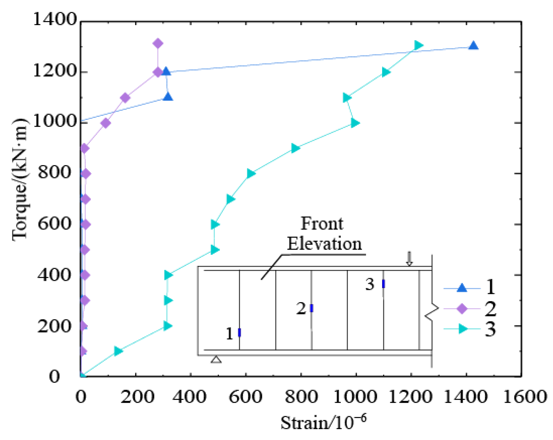
4.3.3. Stirrup Strain

The strain measured at the stirrup monitoring points during loading is shown in Figure 7. In the initial loading stage (before cracking), the growth rate of the stirrup strain was relatively low, indicating that the principal tensile stress in the concrete was primarily resisted by both the concrete itself and the compressive stress induced by prestressing, with stirrups not yet fully engaged. As the load increased to LC9 (approximately 900 kN·m), the principal tensile stress in the web concrete exceeded its tensile strength, leading to the initiation and propagation of diagonal and flexural cracks, which triggered an internal force redistribution. Consequently, load transfer from the concrete to the stirrups occurred, causing a significant increase in the stirrup strain rate. Measurement point 3 (located in the upper portion of the stirrups) exhibited the largest strain amplitudes. This was primarily due to the torsional effect, which induced significant circumferential shear stress at the junction of the T-beam’s top flange and web, causing the upper stirrups to bear increased tensile stress. The sudden increase in strain at measurement point 1 (near the support) was attributed to the combined effects of shear force and torque near the support, which led to a dense formation of diagonal cracks. The propagation of these cracks caused the stirrups to bear greater tensile forces. In contrast, the stirrup strain magnitudes at the middle measurement point 2 were relatively small, as the shear stress in the lower web was inherently lower, and the prestress-induced compressive stress further reduced the load carried by the stirrups.

5. Conclusions

To investigate the torsional performance of a 30 m pre-tensioned polygonal prestressed T-beam, a full-scale model test was conducted. By integrating multiple sensor-based measurement techniques and computational analysis, the crack development pattern, deformation characteristics, and other structural behaviors were studied. The following conclusions were drawn:
(1) Compared with the crack development patterns observed under pure bending, shear, or torsion, the crack characteristics revealed in this study exhibit significant differences. Specifically, under pure bending, cracks are predominantly vertical, originating at the bottom of the mid-span and propagating upward along the web, with a relatively regular distribution. Under pure shear, typical diagonal cracks initiate near the supports and extend toward the loading region, characterized by steep angles and rapid penetration. In the case of pure torsion, cracks appear in a helical pattern around the web, forming densely spaced and diagonally interlaced cracks. In contrast, the combined action of bending, shear, and torsion induces a more complex crack evolution mechanism, manifesting as a hybrid pattern of vertical, diagonal, and spiral cracks. These cracks exhibit highly variable orientations and irregular development, with a clearly asymmetric distribution between the two sides of the beam. The experimental findings provide a reliable basis for understanding the damage evolution of zigzag-shaped pre-tensioned prestressed T-beams under combined loading, offering important insights for crack resistance design and structural safety evaluation.
(2) After the cracking of the concrete web, both the stirrup strain and concrete strain exhibited abrupt changes. The peak strain in the upper stirrups was significantly higher than that in the middle and lower sections. On the front elevation of the web, the principal strain peak was concentrated near the connection line between the loading bottom and the upper support. In contrast, on the back elevation of the web, the principal tensile strain was more pronounced near the connection line between the loading top and the lower support.
(3) The ratio of the calculated cracking torque to the experimentally measured value was 1.16, indicating that the pre-tensioned polygonal prestressed T-beam exhibited a good reserve capacity against cracking under combined bending, shear, and torsion. Furthermore, the current code-based calculation methods provide a useful reference for the crack resistance design of beams subjected to combined bending, shear, and torsion.
Building upon the findings of this study, future research will focus on the development and validation of refined numerical models to simulate the complex mechanical behavior of polygonal pre-tensioned T-beams under combined bending, shear, and torsion [28,29,30,31,32,33]. A systematic parametric analysis will be conducted to investigate the influence of key variables such as web thickness, torsion-to-shear ratio, and the bend angle of the prestressing tendons on the torsional capacity and overall performance. These efforts aim to further enhance the understanding of the torsional behavior and design optimization of such innovative beam structures.

Author Contributions

Conceptualization, Z.Y. and D.Y.; Methodology, G.L., M.W. and H.Y.; Validation, H.Y., M.W. and C.Z.; Investigation, Z.Y.; Writing—original draft preparation, Z.Y.; Writing—review and editing, D.Y. and G.L.; Supervision, D.Y., M.W. and C.Z.; Project administration, J.T. and H.P.; Funding acquisition, J.T. and H.P. All authors have read and agreed to the published version of the manuscript.

Funding

This research was funded by the Jiangxi Provincial Department of Transport Science and Technology Project (grant No. 2024ZG001).

Data Availability Statement

Data are contained within the article.

Acknowledgments

The financial support provided by this research fund is greatly appreciated by the authors.

Conflicts of Interest

Author Mingguang Wei, Hai Yan and Chunlei Zhang is employed by the Shanghai Municipal Engineering Design Institute (Group) Co., Ltd. Author Jinglin Tao and Huiteng Pei is employed by the Jiangxi Gan Yue Expressway Co., Ltd. Author Jinglin Tao is employed by the Jiangxi Communications Investment Group Co., Ltd. Author Huiteng Pei is employed by the Jiangxi Communications Design and Research Institute Co., Ltd. The remaining authors declare that the research was conducted in the absence of any commercial or financial relationships that could be construed as a potential conflict of interest.

References

  1. Zhou, K.L.; Qiao, L. Application of non-bonded prestressing technology in ultra-long structures. Ind. Constr. 2023, 53, 238–239. [Google Scholar]
  2. Xia, Y.L.; Zhang, W.; Dai, J. Study on prestress transfer length of concrete beams using self-balanced prestressed hollow tubes. Bridge Constr. 2023, 53, 33–40. [Google Scholar]
  3. Chen, C. Theoretical Analysis and Experimental Study of Flexural Bearing Capacity for Pretensioned Prestressed T-Shaped Concrete Beam with Bent-Tendons. Master’s Thesis, Southwest Jiaotong University, Chengdu, China, 2019. [Google Scholar]
  4. Wu, H. Construction Technology and Quality Control Analysis of Prestressed Concrete T-Beam. Metall. Collect. 2022, 7, 84–86. [Google Scholar]
  5. Lin, Y.; Wang, J.H.; Deng, Q.E. Research on polygonal pretensioning technology for I-beams in Xishamen Bridge. Highway 2022, 67, 218–224. [Google Scholar]
  6. Zhang, C.L. Research on the Application of Prestressing Technology with Pretensioned Draped Strands in Bridge Engineering. Shanghai Highw. 2020, 41–44+48+149. [Google Scholar]
  7. Zhang, Z.; Lin, Y.; Wang, J.; Deng, Q.; Zhang, K. Calculation method of load lateral distribution coefficient of I-beam with deviated pretensioning method and design of cross-girder. Struct. Eng. 2022, 38, 185–191. [Google Scholar]
  8. Wang, R.; Wang, B. Application of folded line first tensioning technology in prefabricated T girders for highway bridges. New Technol. New Prod. China 2023, 102–104. [Google Scholar] [CrossRef]
  9. Du, L.; Wu, D.; Wang, J.; Wang, S.; Zhao, B.; Tang, X. Experimental Study on Flexural Behavior of Retard-Bonded Prestressed UHPC Beams with Different Reinforcement Ratios. Buildings 2025, 15, 887. [Google Scholar] [CrossRef]
  10. Li, H.; Qiu, Y.; Pan, Z.; Yang, Y.; Tang, H.; Ma, F. Experimental Study on the Flexural Performance of the Corrosion-Affected Simply Supported Prestressed Concrete Box Girder in a High-Speed Railway. Buildings 2024, 14, 3322. [Google Scholar] [CrossRef]
  11. Wu, D.; Wang, H.; Wang, R.; Lv, C. Crack Resistance of Pre-Stressed Steel-Reinforced Concrete Composite Simple Supported Beams. Buildings 2024, 14, 201. [Google Scholar] [CrossRef]
  12. Ju, H.; Jung, C.; Cho, H.-C. Strength Model for Prestressed Concrete Beams Subjected to Pure Torsion. Buildings 2024, 14, 2690. [Google Scholar] [CrossRef]
  13. Al-Salim, N.H.; Jaber, M.H.; Hassan, R.F.; Mohammed, N.S.; Hussein, H.H. Experimental Investigation of Compound Effect of Flexural and Torsion on Fiber-Reinforced Concrete Beams. Buildings 2023, 13, 1347. [Google Scholar] [CrossRef]
  14. Zhang, Y.; Li, N.; Wang, Q.; Li, Z.; Qin, X. Shear Behavior of T-Shaped Concrete Beams Reinforced with FRP. Buildings 2022, 12, 2062. [Google Scholar] [CrossRef]
  15. Jiang, H.; Mo, F.; Chen, Z.; Wu, J.; Fang, H.; Fang, Z.; Zhang, S.; Xu, Z. Full-Scale Experimental Study of Shear and Flexural Behavior of 16-m Retired Reinforced Concrete T-Beams. Buildings 2023, 13, 2075. [Google Scholar] [CrossRef]
  16. Zhu, Y.; Shi, T.; Zhu, Y.; Zhu, Z.; Wang, K. Analysis on Flexural Performance of Prestressed Steel-Reinforced UHPC Beams. Buildings 2024, 14, 4029. [Google Scholar] [CrossRef]
  17. Liu, Z.; Lei, H.P.; Luo, J.; Zhang, C.; Ma, B. Full-Scale Experimental Test on Flexural Behavior of a 30 m-Long Pretensioned Concrete Double-Tee Girder. Bridge Constr. 2022, 52, 14–20. [Google Scholar]
  18. Liu, Y.C. Theoretical Analysis and Experimental Study on Mechanical Properties of Simply Supported T-Beams with Single Polygonal Prestressed Tendons. Master’s Thesis, Southwest Jiaotong University, Chengdu, China, 2017. [Google Scholar]
  19. Yang, H.; Dai, M.; Wu, N.; Zheng, M.; Zhang, X. Experimental on mechanical behavior of broken line pretensioned I-beam. Sci. Technol. Eng. 2022, 22, 13484–13489. [Google Scholar]
  20. Hu, K.; Liu, C.; Duanmu, X.Y.; Wang, S.B. Theoretical study on shear capacity of concrete beam sections under combined bending and shear. Bridge Constr. 2023, 53, 135–141. [Google Scholar]
  21. Garber, D.B.; Gallardo, J.M.; Deschenes, D.J.; Bayrak, O. Nontraditional Shear Failures in Bulb-T Prestressed Concrete Bridge Girders. J. Bridge Eng. 2016, 21, 04016030. [Google Scholar] [CrossRef]
  22. Deifalla, A.; Ghobarah, A. Behavior and analysis of inverted T-shaped RC beams under shear and torsion. Eng. Struct. 2014, 68, 57–70. [Google Scholar] [CrossRef]
  23. Deifalla, A.; Awad, A.; Seleem, H.; Abdelrahman, A. Investigating the behavior of lightweight foamed concrete T-beams under torsion, shear, and flexure. Eng. Struct. 2020, 219, 110741. [Google Scholar] [CrossRef]
  24. GB/T 50081-2019; Standard for Test Methods of Concrete Physical and Mechanical Properties. China National Standardization Administration: Beijing, China, 2019.
  25. GB/T 228.1—2021; Metallic Materials—Tensile Testing—Part 1: Method of Test at Room Temperature. China National Standardization Administration: Beijing, China, 2021.
  26. ACI 318-19; Building Code Requirements for Structural Concrete and Commentary. American Concrete Institute: Farmington Hills, MI, USA, 2019.
  27. JTG 3362-2018; Specifications for Design of Highway Reinforced Concrete and Prestressed Concrete Bridges and Culverts. China Architecture & Building Press: Beijing, China, 2018.
  28. Xue, Y.H.; Dong, Z.Q.; Li, G.; Yu, D.H.; Wang, R.; Zhang, H. Multi-mode inversion of dispersive surface-wave free fields in layered media. Earthq. Eng. Struct. Dyn. 2024, 53, 2331–2353. [Google Scholar] [CrossRef]
  29. Yu, D.H.; Li, G. A novel Woodbury solution method for nonlinear seismic response analysis of large-scale structures. Earthq. Eng. Struct. Dyn. 2024, 53, 261–278. [Google Scholar] [CrossRef]
  30. Zhang, J.L.; Li, G.; Yu, D.H.; Dong, Z.Q. Framework for seismic risk analysis of engineering structures considering the coupling damage from multi-environmental factors. J. Struct. Eng. 2024, 150, 1–15. [Google Scholar] [CrossRef]
  31. Li, G.; Yu, D.H. Efficient Inelasticity-Separated Finite Element Method for Material Nonlinearity Analysis. ASCE-J. Eng. Mech. 2018, 144, 04018008. [Google Scholar] [CrossRef]
  32. Zhang, J.L.; Yu, D.H.; Li, G.; Dong, Z.Q. Multi-hazard performance assessment of monopile offshore wind turbine considering coupled corrosion and fatigue damage. Ocean. Eng. 2025, 316, 119985. [Google Scholar] [CrossRef]
  33. Li, G.; Jiang, Y.M.; Yu, D.H.; Dong, Z.Q. A mixed stochastic waves model for analyzing offshore structures considering engineering characteristics correlation of wind-generated-wave and swell. Ocean. Eng. 2024, 314, 119671. [Google Scholar] [CrossRef]
Figure 1. Pre-tensioned polygonal prestressed T-beam structure (Unit: mm): (a) pre-tensioned polygonal prestressed T-beam; (b) half-elevation of the T-beam; (c) cross-section of the T-beam.
Buildings 15 01379 g001aBuildings 15 01379 g001b
Figure 2. Pre-tensioned polygonal prestressed T-beam test loading device diagram: (a) front elevation schematic of the loading device; (b) cross-section diagram schematic of the loading device; (c) overall view of the loading setup at the test site.
Buildings 15 01379 g002
Figure 3. Distribution of cracks and cracks development process in the test section of full-scale model beam.
Buildings 15 01379 g003
Figure 4. Force relationships and displacement: (a) torque/twist ratio relationships; (b) moment–displacement curve; (c) shear–displacement curve.
Buildings 15 01379 g004
Figure 5. Torque—principal strain curve of concrete.
Buildings 15 01379 g005
Figure 6. Principal tensile strain distribution of the beam based on VIC-3D technology.
Buildings 15 01379 g006aBuildings 15 01379 g006b
Figure 7. Torque–strain curve of stirrups.
Buildings 15 01379 g007
Table 1. Measured material properties.
TypeDiameter (mm)Yield Strength fy (MPa)Ultimate Strength fu (MPa)
No. 1 bars10332.0461.2
No. 2 bars12418.0595.4
No. 3 bars14446.0580.4
No. 4 bars28432.0614.1
Prestressing strands15.21383.31834.6
Table 2. Loading cases of pre-tensioned polygonal prestressed T-beam full-scale test.
Loading ConditionsA1 Load (kN)A2 Load (kN)Torque (kN·m)Note
LB11271270Self-weight and secondary dead loads
LC1280127100
LC2435127200
LC3590127300
LC4745127400
LC5900127500
LC61055127600
LC71210127700
LC81365127800
LC91520127900Cracking
LC101620127970
LC1117201271035
LC1218201271100
LC1319201271165
LC1420201271230
LC1521201271295
LC16000Unloading
Table 3. Information on the hydraulic jack.
NumberMeasurement Range/kNSensitivity/(mV/V)Operating Temperature Range/°C
Jack A10–30001.2437−10~+70
Jack A20–10001.4260−10~+70
Disclaimer/Publisher’s Note: The statements, opinions and data contained in all publications are solely those of the individual author(s) and contributor(s) and not of MDPI and/or the editor(s). MDPI and/or the editor(s) disclaim responsibility for any injury to people or property resulting from any ideas, methods, instructions or products referred to in the content.

