Article

Enhanced Ventilation and Energy Efficiency of an Optimized Double-Channel Solar Chimney

1
Department of Landscape and Architecture, Zhejiang Agriculture and Forestry University, Hangzhou 311300, China
2
Bureau of Housing and Urban-Rural Development of Pingyang County, Wenzhou 325400, China
3
China Construction Fifth Engineering Division Co., Ltd., Hangzhou 311300, China
*
Authors to whom correspondence should be addressed.
These authors contributed equally to this work.
Buildings 2025, 15(8), 1380; https://doi.org/10.3390/buildings15081380
Submission received: 16 March 2025 / Revised: 11 April 2025 / Accepted: 17 April 2025 / Published: 21 April 2025
(This article belongs to the Section Building Energy, Physics, Environment, and Systems)

Abstract

:
This study explores the use of solar chimneys to harness solar radiation, generating a chimney effect that promotes natural ventilation in buildings. However, the performance of double-channel solar chimneys is heavily influenced by their installation conditions. We propose an optimized double-channel solar chimney with a deflector placed at the base of the collector. Through numerical simulations, we analyze how different deflector installation conditions affect the ventilation performance of the optimized system. Key parameters for the deflector installation include its angle and length. Our findings reveal that the optimal configuration for the double-channel solar chimney occurs when the deflector has a horizontal angle of γ = 35° and a length-to-diameter ratio (l/D) of 0.3. Under a solar radiation intensity of 800 W/m2, the optimized system achieved a ventilation rate of 0.185 kg/s and a thermal efficiency of 41.2%. Compared with conventional double-channel solar chimneys, this configuration enhanced ventilation performance by 8.2% and increased thermal efficiency by 7.4%. In the calculations, the optimized system resulted in a 13.6% reduction in energy consumption, underscoring its potential for sustainable architectural design.

1. Introduction

Amidst global population growth, energy consumption has emerged as a critical worldwide concern [1]. The building sector, recognized as the largest energy consumer globally, dedicates a substantial portion of its energy usage to heating, ventilation, and air conditioning (HVAC) systems [2]. To address this, buildings are increasingly expected to adopt energy-efficient designs that partially or fully replace fossil fuels with renewable energy sources—particularly solar energy—for heating and cooling. In the post-pandemic era, indoor air quality has gained heightened importance, as effective natural ventilation can significantly enhance indoor air quality and meet the human demand for healthy, fresh air. Solar chimneys have proven to be a robust solution for achieving building sustainability and improving indoor air quality [3,4], while simultaneously integrating architectural aesthetics with functional value [5]. A conventional solar chimney comprises a solar collector, insulation walls, and a glass cover, forming a heating channel. When solar radiation penetrates the glass cover and is absorbed by the collector, the collector’s temperature rises. Heat exchange between the collector and the internal air alters the temperature gradient between the chimney’s interior and the exterior. Driven by the chimney effect, heated air is expelled upward, thereby enhancing ventilation performance [6].
The ventilation performance of solar chimneys is significantly influenced by diverse factors. Shi et al. [7] comprehensively categorized these parameters into four groups: structural factors (e.g., height, width), installation conditions (e.g., tilt angle, inlet/outlet heights), material properties (e.g., phase-change materials (PCMs), glass types), and external environmental factors (e.g., solar radiation, wind speed). With regard to structural factors, Hosien et al. experimentally demonstrated that increasing the chimney channel width reduces frictional resistance on airflow, thereby significantly enhancing the air mass flow rate [8]. However, Xu et al. noted that when the channel width exceeded 0.5 m, reverse flow at the outlet and vortex formation within the channel degraded ventilation efficiency, ultimately reducing airflow [9]. Regarding material properties, glass and collector materials play critical roles [10]. Lee and Strand [11] utilized EnergyPlus simulations to show that increasing the solar absorptivity of the collector from 0.25 to 1.0 boosted air velocity by 57% and improved the flow rate by 42%. To assess the effects of external environmental factors, Zhang et al. [12] employed CFD simulations to demonstrate that solar chimney thermal efficiency increased markedly from 16.3% to 67.4% as solar irradiance increased from 400 to 1000 W/m2.
Recent research has focused on improving solar chimney ventilation performance through optimized installation conditions. In Iraq, Imrān et al. [13] found that a 60° tilt angle for tilted solar chimneys maximized ventilation rates, achieving 20% higher airflow than a 45° tilt. A parametric study by Bassiouny and Koura [14] showed that increasing the inlet cross-sectional area threefold improved air changes per hour (ACH) by 11%. Han M [15] installed a 25° flow deflector at the inlet of a composite solar chimney, enhancing ACH by 6.72%. However, these studies focused on single-channel solar chimneys. Double-channel chimneys, with their different structural features, may require different considerations, such as deflector placement and heat transfer, which means that findings for single-channel systems may not apply directly to dual-channel ones. Further research is needed to optimize double-channel solar chimneys.
Research on factors influencing the ventilation performance of double-channel solar chimneys remains in its preliminary stages. Arce et al. [16] proposed a double-channel configuration including a thermal collector centrally positioned within the chimney’s airflow channel, forming two vertical air passages between the collector, glass cover, and building envelope. Vargas-López et al. [17] developed a transient model for PCM-enhanced double-channel solar chimneys, demonstrating improved daytime collection efficiency following integration of an absorber wall. Zavala-Guillén et al. developed a novel double-channel solar chimney with fully glazed enclosures, observing a 50% increase in daytime mass flow rates, although their analysis was limited to the impact on enclosure materials [18]. Lei et al. [19] introduced a double-channel system with a porous thermal collector, revealing through numerical simulations that a 60° tilt angle enhanced gas flow rates by 35%. However, they considered only the structure of the solar collector and did not take into account the influence of installation conditions.
Systematic analysis of the literature reveals that dual-channel solar chimneys are emerging at the forefront of research into renewable energy-enhanced building ventilation. However, significant limitations persist in understanding the factors influencing their performance. Current investigations predominantly focus on configuration (height/gap ratio, inlet and outlet areas) and environmental variables (solar irradiance, wind pressure coefficients), whereas critical factors including installation configurations and material innovations remain underexplored. In addition, although the installation of deflectors has been studied in single-channel solar chimneys, their impact on the performance of double-channel solar chimneys has not been explored, and there is a lack of relevant recommendations regarding deflector installation conditions. Therefore, this study aimed to investigate the application of deflectors in double-channel solar chimneys and their impact on performance.
To systematically evaluate the impact of flow deflector installation conditions on the ventilation performance of double-channel solar chimneys, this study combines field measurements of a prototype chimney with numerical simulations of an identical structure using ANSYS Fluent 2021, validating and calibrating the numerical model against experimental data. A parametric analysis was conducted by establishing 12 deflector angles (γ = 0°–90°, Δγ = 5°–10°) and seven deflector lengths (l/D = 0–0.6, Δl/D = 0.1). Steady-state simulations were conducted in ANSYS Fluent to obtain the ventilation rates and thermal efficiencies for each configuration. The optimal installation conditions for the deflector of the optimized solar chimney were finally determined and applied to the building. The improvement in natural ventilation performance and the energy-saving efficiency of the optimized double-channel solar chimney were calculated. The technical route is shown in the Figure 1.

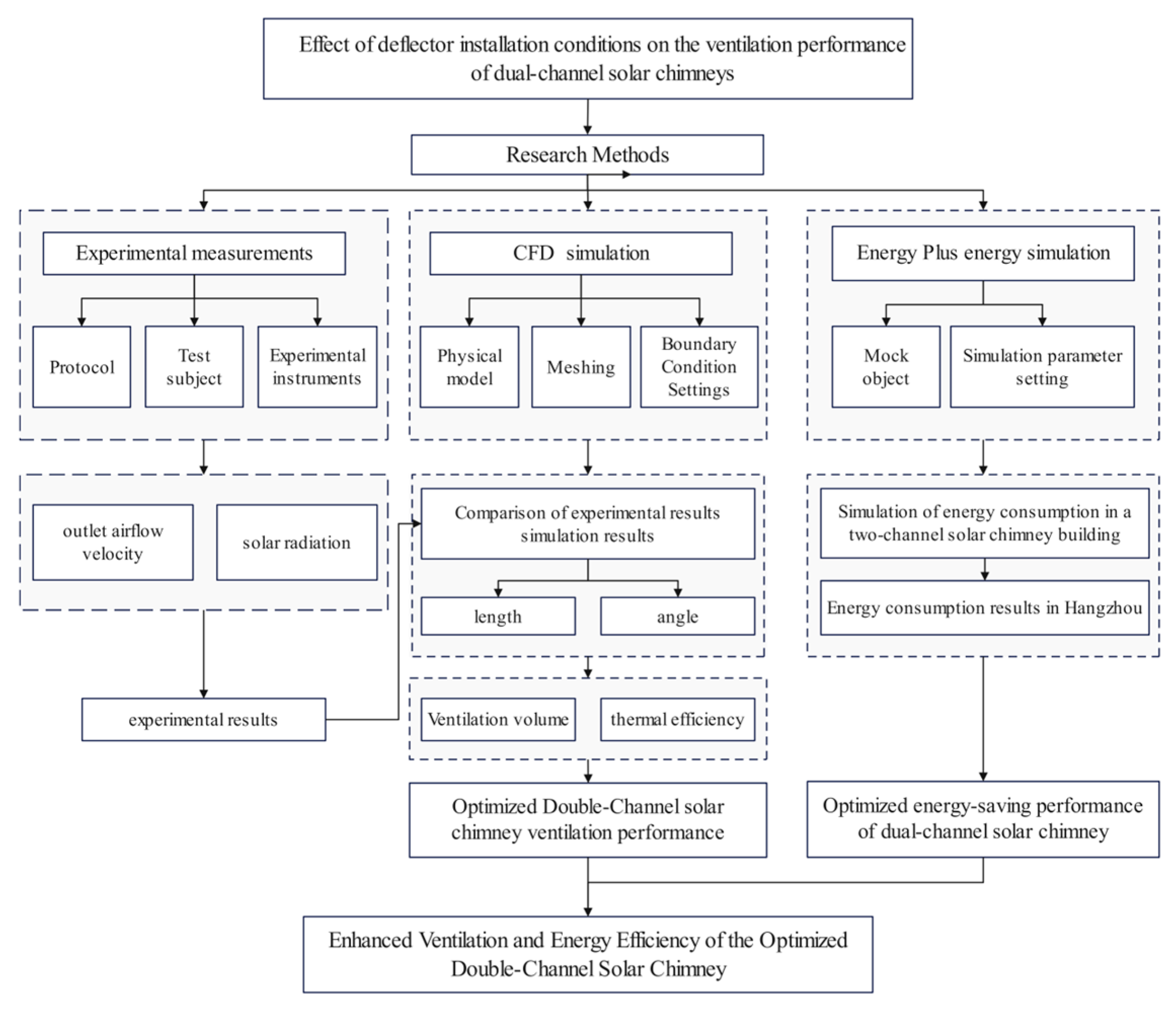
2. Numerical Simulation

This study investigated the ventilation performance of a dual-channel solar chimney using the software ANSYS Fluent 2021. The process included physical model establishment, setup of boundary conditions, mesh generation, and independence verification, among other steps.

2.1. Physical Models for Numerical Simulations

As depicted in Figure 2, the optimized dual-channel solar chimney consists of a glass cover, absorber plate, deflector, and enclosure structure. The chimney has a total height of H = 3 m, width L = 1.2 m, and depth D = 0.5 m, with an inlet of height h = 0.3 m positioned adjacent to the heat-absorbing wall, and an outlet located at the chimney’s top. The left side of the chimney features a transparent glass cover, while the right side incorporates an adiabatic wall to minimize thermal losses. Inside the chimney, a solar collector with dimensions l1 = 2.4 m (length) and L1 = 1.2 m (width) is installed. A deflector with an adjustable inclination angle and length is positioned beneath the solar collector. Solar radiation penetrates the glass cover, heating the solar collector and increasing the temperature of the air within the chimney. This thermal gradient generates a buoyancy-driven airflow, enhancing ventilation performance through increased differences in thermal pressure.

2.2. Simulation Condition Setting

Due to the complex airflow and heat exchange processes inside the solar chimney, adding subtle simulation conditions would have little impact on the final simulation results, but it would increase the number of grid points and the difficulty of achieving computational convergence. In order to simplify the simulation calculation process, it was necessary to make the following reasonable assumptions [20]:
(1)
The air is an ideal incompressible gas, usually using the Boussinesq assumption;
(2)
The physical properties of the air inside the solar wall chimney are constant, and the air density is the only variable;
(3)
The viscous dissipation of air in the flow channel can be ignored;
(4)
The shell’s heat transfer loss and the outer wall’s radiant heat loss can be ignored.

2.3. Control Equations and Calculation Methods

Considering that the flow of air in the dual-channel solar chimney is turbulent, the standard k-ε turbulence model was employed for the momentum equations [21,22]:
u x x + u y y + u z z = 0
( ρ u x ) t + ( ρ u x 2 ) x + ( ρ u x u y ) y + ( ρ u x u z ) z = p y + μ 2 u y x 2 + 2 u y y 2 + 2 u y z 2 + ρ 0 g ρ β ( T T 0 ) g
( ρ u z ) t + ( ρ u x u z ) x + ( ρ u y u z ) y + ( ρ u z 2 ) z = p z + μ 2 u z x 2 + 2 u z y 2 + 2 u z z 2
where ux, uy, uz is the velocity of the fluid in the x, y, z direction and µ is the dynamic viscosity of the fluid.
( ρ k ) t + ( ρ k u i ) x i = x i α k μ eff k x i + G k ρ ε
( ρ ε ) t + ( ρ ε u i ) x i = x i α ε μ eff ε x i + C 1 ε G k k C 2 ε ρ ε 2 k
where k represents the turbulent pulsation kinetic energy, ε denotes the dissipation rate of turbulent pulsating momentum, μ eff is the effective dynamic viscosity of the fluid, αε refers to the inverse of the effective Prandtl number for ε, and G k is the inverse of the effective Prandtl number k . G k indicates the kinetic energy of the turbulent flow generated by the average velocity gradient [23]. The constants C and C are default values used in the calculations, set to 1.32 and 1.41, respectively, while α ε is the approximate Prandtl number for the dissipation rate, which is 1.2 [24].

2.4. Boundary Condition Settings

The boundary conditions for the numerical simulations were defined as follows. A convective heat transfer boundary condition was applied to the transparent cover, with a free-stream temperature of 300 K (26.85 °C) and a convective heat transfer coefficient of 10 W/(m2·K). For the thermal collector, a fluid-solid conjugate boundary condition was adopted to align the simulations with real-world conditions. The radiation model was selected as the solar radiation model with DO discrete coordinates, and the SIMPLE pressure–velocity coupling algorithm was used to solve the discretized control equations. In this simulation study, Hangzhou, China (118°21′ E–120°30′ E, 29°11′ N–30°33′ N) was selected as the geographic focus to align the computational conditions with local climatic and solar irradiance characteristics. The walls were assigned a no-slip condition (i.e., U = V = 0) and treated as adiabatic surfaces, assuming negligible solar radiation absorption. Pressure inlet and outlet boundaries were set to default gauge pressure (p = 0), while the outdoor air temperature was fixed at 300 K (26.85 °C) (representing the summer average for the studied city). The indoor temperature was set to 296 K (22.85 °C), within the thermal comfort range specified by HVAC standards. Turbulence intensity of 2% was applied to both the inlet and outlet. The material properties of the model components are detailed in Table 1.The thermophysical properties parameters of air are detailed in Table 2.

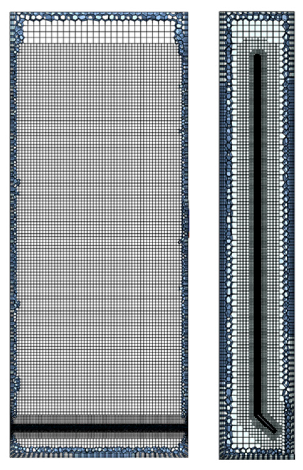
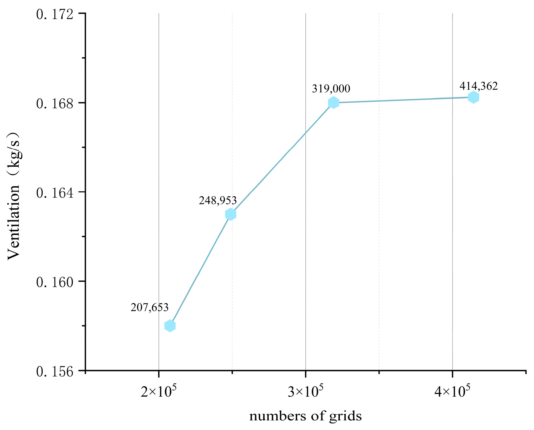
2.5. Grid Independence Verification

In computational simulations, the computational domain is first discretized into a mesh. Due to the geometric complexity of the model in the current study, an unstructured octahedral mesh was adopted for the chimney interior, with a representative local mesh as illustrated in Figure 3. To ensure accurate results while optimizing computational resources, a grid independence study was conducted using four mesh configurations with element counts of 207,653, 248,953, 319,000, and 414,362. The ventilation rates within the airflow channel were computed across these meshes. Numerical results (Figure 4) demonstrated that the ventilation rates from the third (319,000 elements) and fourth (414,362 elements) meshes exhibited deviation of less than 1%, indicating convergence. Considering both computational precision and processing speed, the third mesh (319,000 elements) was selected for the subsequent simulations.

3. Experimental Measurement

This section reports the experimental measurements carried out on a dual-channel solar chimney, with cross-verification between the experimental data and CFD numerical simulation results to validate the effectiveness of the simulations.

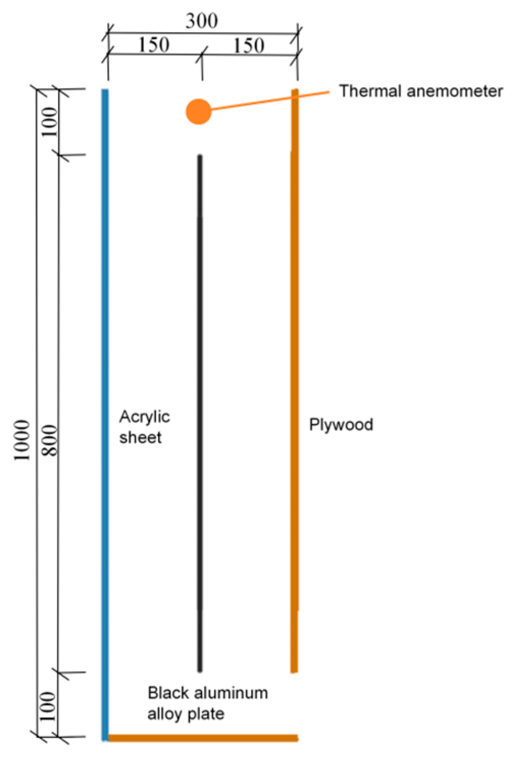
3.1. Experimental Subject and Testing Instruments

The experimental study employed the solar chimney model depicted in Figure 5 for data collection. The ventilation cavity within the chimney body had a net dimension of 1000 mm (height) × 400 mm (width) × 300 mm (depth). The chimney structure consisted of three sides constructed from 20 mm thick plywood panels and one side made of a 2 mm thick transparent acrylic panel for observational access. A central 3 mm thick aluminum alloy plate (1000 mm height × 400 mm width), coated with black spray paint on both sides to enhance solar absorption, was positioned within the chimney. The inlet and outlet openings measured 100 mm (height) × 400 mm (width) and 300 mm (length) × 400 mm (width), respectively. As shown in Figure 6, thermal anemometers were installed at the air outlet of the solar chimney, with measurement points positioned at the centerline of the chimney channel and 950 mm above the base plate. The Ruiyika solar pyranomete was mounted adjacent to the solar chimney setup, ensuring it remained unobstructed by the chimney structure during experiments to maintain the accuracy of the solar irradiance data. To minimize the impact of outdoor wind disturbances on experimental accuracy, a windbreak structure was implemented at the chimney inlet during testing.
The experimental measurements employed a suite of instruments to comprehensively monitor airflow dynamics and solar radiation parameters, as detailed in Table 3. A Biaozhi GM8903 thermal anemometer was utilized to measure airflow velocity, capturing real-time wind intensity data essential for assessing ventilation effectiveness. Simultaneously, a Ruiyika solar pyranometer was deployed to quantify the total solar irradiance incident on the solar chimney.

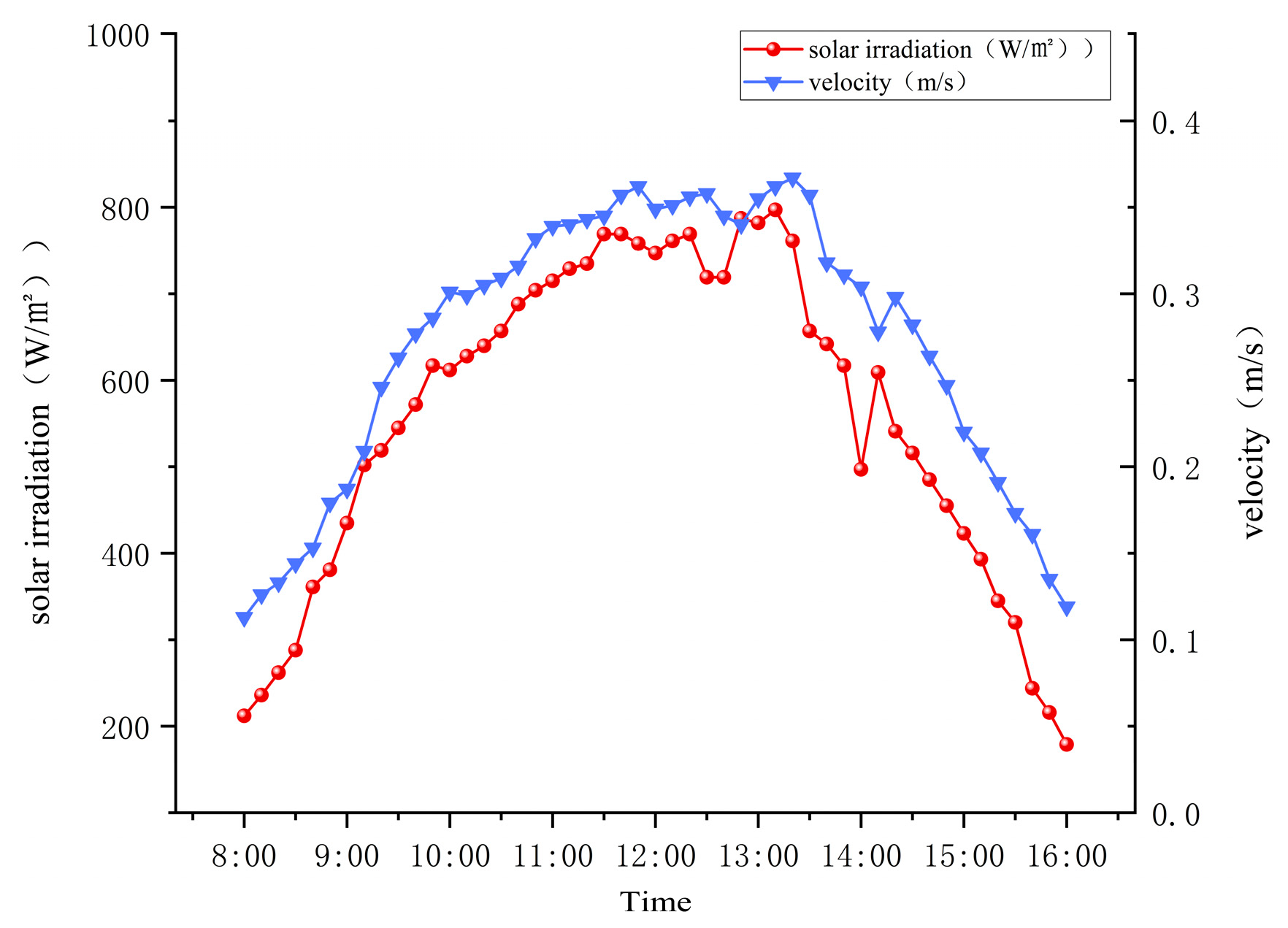
3.2. Experimental Details

The experimental study was conducted on a fifth-floor outdoor platform at the College of Landscape Architecture and Architecture at Zhejiang A&F University, selected for its unobstructed solar exposure. The solar chimney’s glass facade was oriented southwest to maximize the capture of solar irradiance during winter conditions. Testing occurred on 13 January 2025 from 08:00 to 16:00, encompassing peak solar hours. During the experiment, data were recorded every 10 min, mainly documenting the ventilation conditions inside the solar chimney at different time points under various operating conditions, as well as the solar radiation intensity. Data logging commenced 1 h prior to and concluded 1 h after the formal experimental period to account for thermal inertia and environmental stabilization.

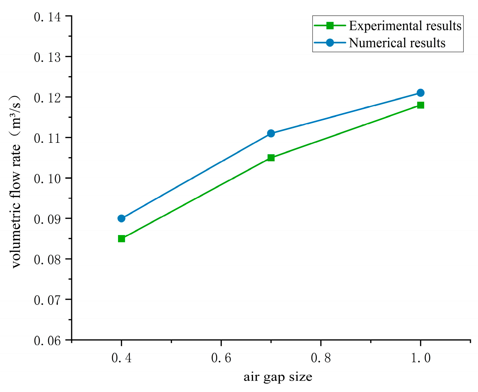
3.3. Verification of Results

Figure 7 illustrates the diurnal variations in outlet airflow velocity and solar radiation intensity for the experimental setup. As shown, the solar radiation intensity between 08:00–16:00 ranged from 200 to 800 W/m2, exhibiting an initial increase followed by a gradual decline, with peak irradiance occurring between 11:00–13:00. The airflow velocity at the measurement points within the channel closely tracked the fluctuations in solar radiation intensity, a demonstrating nearly identical temporal trend.
The comparison of computed velocity and the measured results is shown in Figure 8. The simulated velocities consistently exceeded the measured values, with discrepancies attributed to differences in the surface resistance of wall materials (plywood panels and aluminum alloy sheets) under actual versus idealized conditions, as well as unaccounted aerodynamic resistance at the chimney’s inlet and outlet openings. Despite these deviations, the simulated and experimental trends aligned closely, with errors controlled within 10%. This agreement validates the accuracy of the numerical framework and confirms its reliability for predicting solar chimney performance under real-world constraints.
The reliability of the simulation was verified using previous experimental data [25]; the solar chimney settings in the reference paper were set to a height of 2 m, a width of 1 m, and air gaps ranging from 0.4 m to 1 m. A comparison was made between different gap sizes at solar radiation levels below 300 W/m2, as shown in Figure 9. It was observed that the predicted data aligned well with the measured data, with the maximum difference being 7.9% and the average difference being 4.8%, thereby confirming the validity and accuracy of the simulated numerical results.

4. Results and Discussion

Through CFD simulation analysis of different deflector angles and lengths, ventilation volume and thermal efficiency data under the various working conditions were obtained to determine the optimal installation parameters for the deflector.

4.1. Effect of Deflector Length on Chimney Ventilation Performance

4.1.1. Impact on Ventilation Rate

Figure 10 illustrates the velocity contours and streamline distributions of double-channel solar chimneys with different deflector lengths. Compared with double-channel solar chimneys without flow deflectors, the deflector-equipped configurations exhibit reduced vortex region areas in the inner channel and enhanced airflow velocity within the same channel. As the deflector length increases, the vortex regions in the outer channel of the solar chimney shift gradually from the lower end of the collector to the lower end of the deflector, with the vortex area decreasing initially before expanding. The velocity contours further reveal that the outlet airflow velocity first increases and then decreases with increasing deflector length.
Figure 11 illustrates the variations in ventilation rate at a width of 0.6 m for double-channel solar chimneys with varying deflector lengths. A comparative analysis between the deflector-equipped configuration (l/D = 0.1) and the baseline design (no deflector) revealed that even a minimal deflector length increased the ventilation rate by approximately 1.8%. The ventilation rate exhibits a non-monotonic relationship with deflector length (l/D). As the deflector length increases from l/D = 0.1 to 0.3, the ventilation rate progressively rises. However, when the deflector length further extends within the range l/D = 0.3 to 0.6, the ventilation rate gradually decreases. At l/D = 0.6, the ventilation rate decreases to 0.158 kg/s, representing a 3.1% reduction compared with the traditional double-channel solar chimney. When the deflector length is set to l/D = 0.3, the double-channel solar chimney achieves optimal ventilation performance with the ventilation rate increasing from 0.161 kg/s (baseline) to 0.170 kg/s—a 5.59% enhancement.

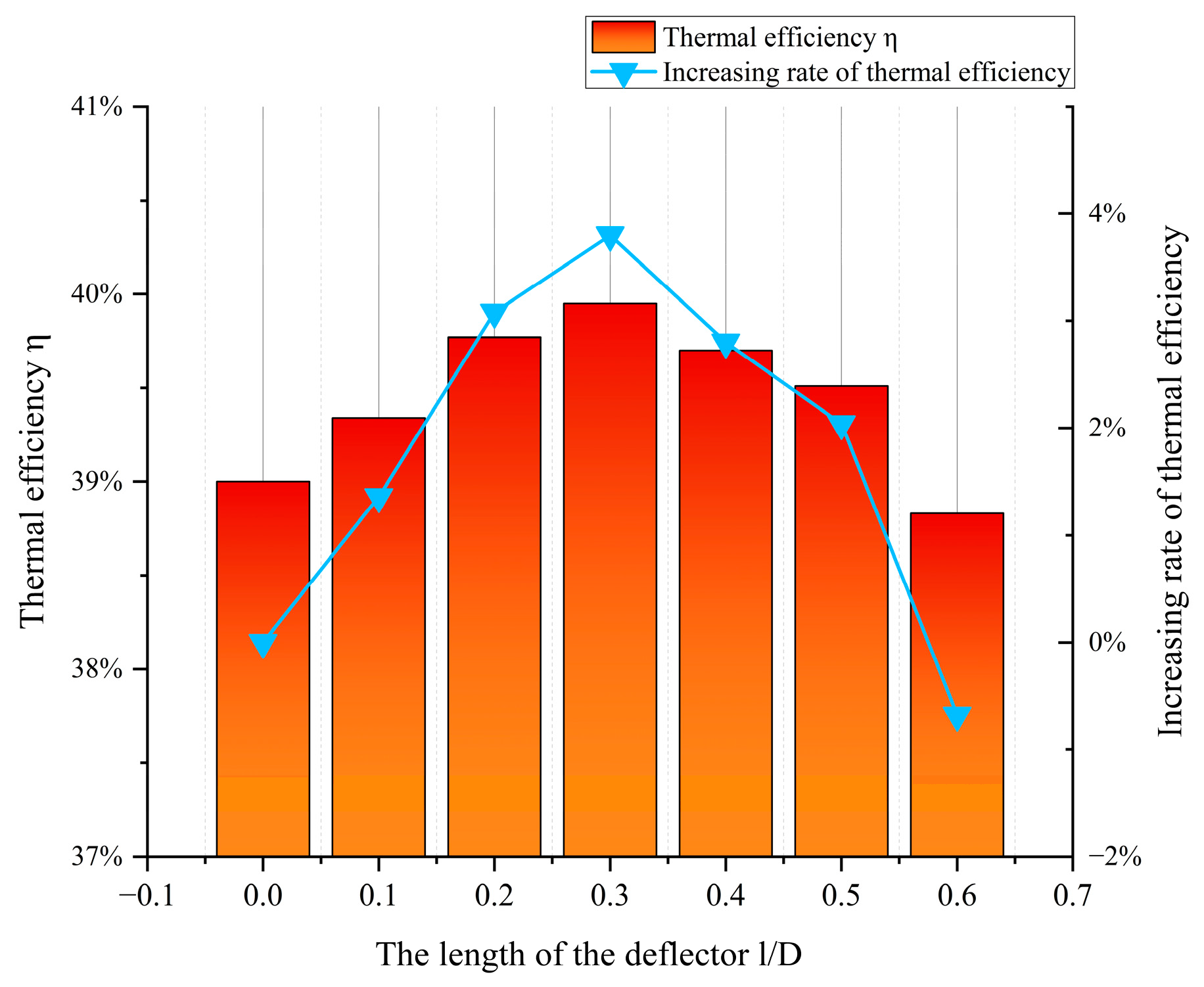
4.1.2. Impact on Thermal Efficiency

The variation in thermal efficiency (η) with deflector length in the dual-channel solar chimney is illustrated in Figure 12. When the deflector length was 0 ≤ l/D ≤ 0.3, the thermal efficiency exhibited a positive correlation with deflector elongation. During this stage, increasing the deflector length enhanced the solar chimney’s thermal performance by effectively guiding hot airflow and reducing heat losses. However, a reverse trend emerged at 0.3 ≤ l/D ≤ 0.6, whereby thermal efficiency decreased with further deflector elongation. Excessive deflector length introduced areas of unnecessary heat exchange while impeding normal airflow. Except for the case with l/D = 0.6, all configurations achieved thermal efficiency improvements, of 1.36%, 3.08%, 3.8%, 2.8%, and 2.04%, respectively. The optimal thermal efficiency of 39.95% occurred at l/D = 0.3, demonstrating the deflector’s peak performance in terms of thermal optimization.

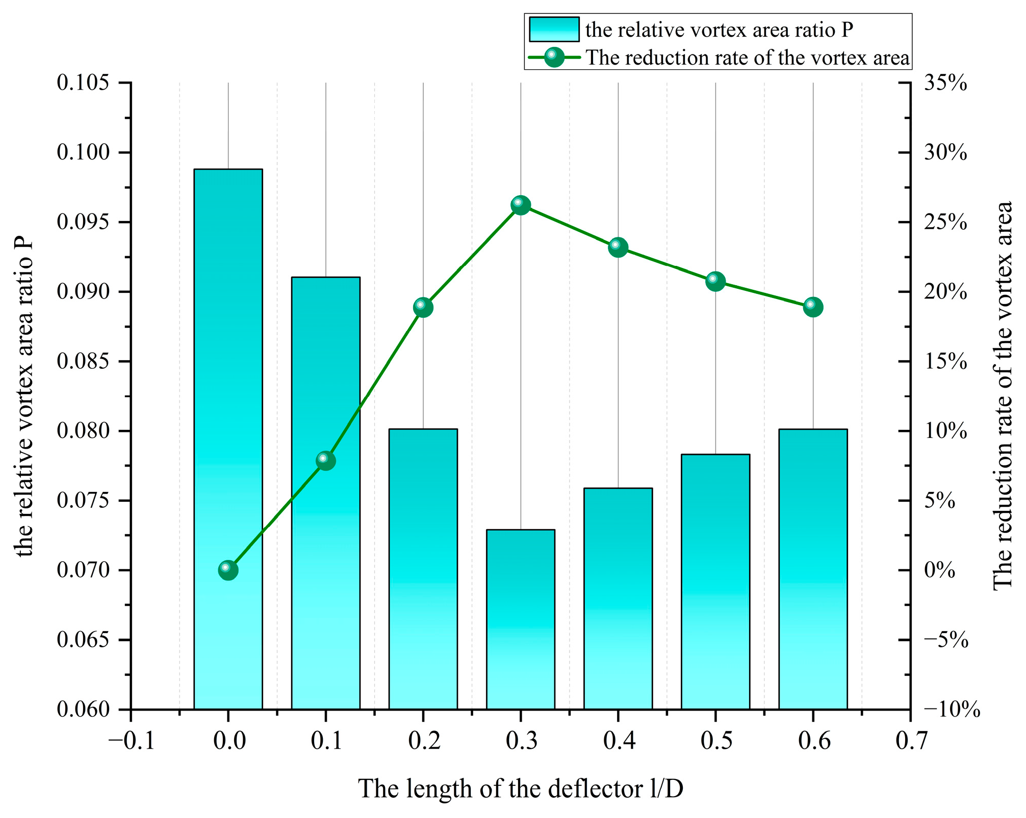
4.1.3. Analysis of Vortex Area in the Chimney

Figure 13 demonstrates the variation in the relative vortex area ratio P (defined as P = S0/S, where S0 is the vortex zone area and S is the cross-sectional area of the solar chimney channel) with the deflector length. The deflector-equipped solar chimney exhibited consistently lower P values compared with the conventional dual-channel design. The P ratio initially decreased and then increased with deflector elongation, achieving reductions in vortex area ranging from 7.8% to 26.2%. The minimum value occurred at l/D = 0.3, corresponding to a 26.2% reduction relative to the baseline configuration without deflectors.
The vortex regions in a solar chimney with varying deflector lengths are shown in Figure 14. For 0 ≤ l/D ≤ 0.3, both inner and outer channel vortex areas progressively diminished, with vortex cores shifting toward the lower region of the deflector. This spatial reorganization reduced the vortex height at the collector base by 18.6%, enhancing thermal exchange efficiency through streamlined airflow. However, expansion of outer-channel vortex areas was observed at 0.3 ≤ l/D ≤ 0.6, and this was particularly severe at l/D = 0.6. The 30 cm deflector (l/D = 0.6) induced flow separation at the deflector–collector interface. Compounding this issue, the restricted inlet dimensions meant that the airflow was reliant on thermal driving forces from the inner channel, which provided substantially weaker energy input compared with the combined solar and thermal radiation effects in the outer channel, ultimately degrading the overall ventilation performance.

4.2. Influence of Deflector Angle on Chimney Ventilation Performance

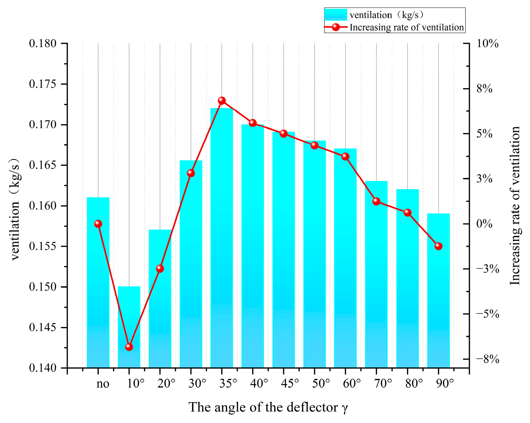
4.2.1. Impact on Ventilation Rate

The airflow characteristics of the dual-channel solar chimney with varying deflector angles (γ) are illustrated in Figure 15, which shows velocity contours and streamline patterns. When the deflector is inclined at angles between 10° and 20° relative to the horizontal plane, vortex zones predominantly form above the deflector, resulting in stagnant airflow within the inner channel and less efficient convective heat transfer. As the deflector angle increases to γ ≥ 30°, the redistribution of vortex zones in both the inner and outer channels enlarges the effective heat exchange area between the absorber plate and the airflow, leading to improved ventilation. However, at extreme angles (γ ≥ 70°), the outer-channel vortex area expands substantially, obstructing the airflow at the chimney outlet and reducing the outlet velocity.
Figure 16 presents the variation in ventilation rate with deflector angle for a width of 0.6 m. The ventilation rate initially increases and then decreases as the deflector angle γ increases. For angles γ ≤ 20°, the ventilation rate remains 6.8% (γ = 10°) and 2.4% (γ = 20°) lower than that of the baseline deflector-free configuration. Peak performance occurs at γ = 35°, where the ventilation rate rises from 0.161 kg/s to 0.172 kg/s, representing a 6.8% enhancement. Conversely, at γ = 90°, the ventilation rate drops to 0.159 kg/s, 1.3% below the baseline value.

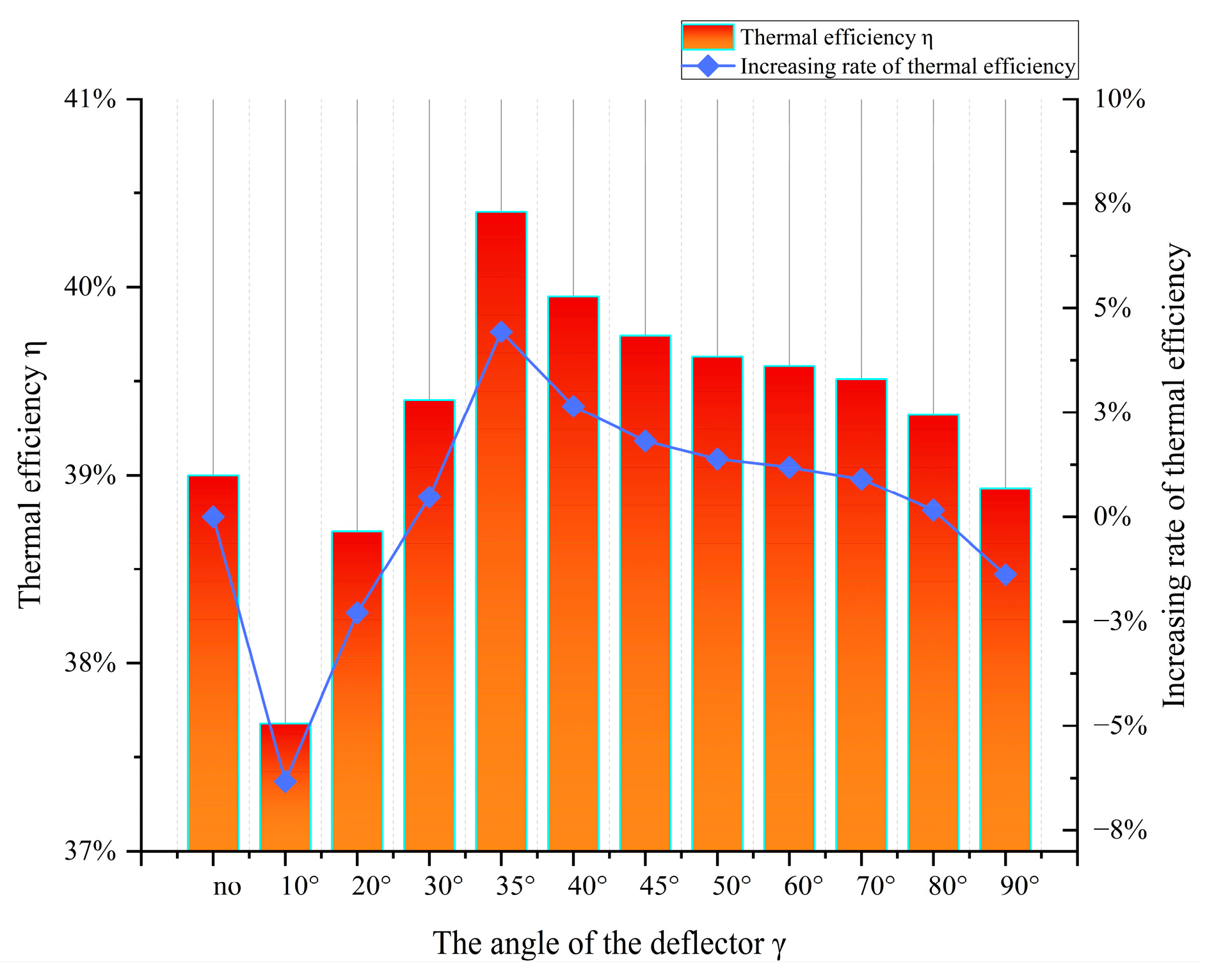
4.2.2. Impact on Thermal Efficiency

Figure 17 illustrates the variation in thermal efficiency in the dual-channel solar chimney with the deflector angle (γ). The baseline configuration without deflectors achieved a thermal efficiency of 38.2%. The maximum thermal efficiency of 40.4% was observed at γ = 35°, representing a 4.4% improvement over the baseline. When the deflector angle ranged between 10° and 35°, thermal efficiency increased progressively with the angle, rising from 37.7% at γ = 10° to its peak value of 40.4% at γ = 35°. Conversely, for angles between 35° and 90°, thermal efficiency exhibited a declining trend, dropping to 38.9% at γ = 90°. Notably, specific configurations with deflector angles of γ = 10°, 20°, and 90° underperformed relative to the baseline, yielding thermal efficiencies of 37.7%, 38.6%, and 38.9%, respectively.

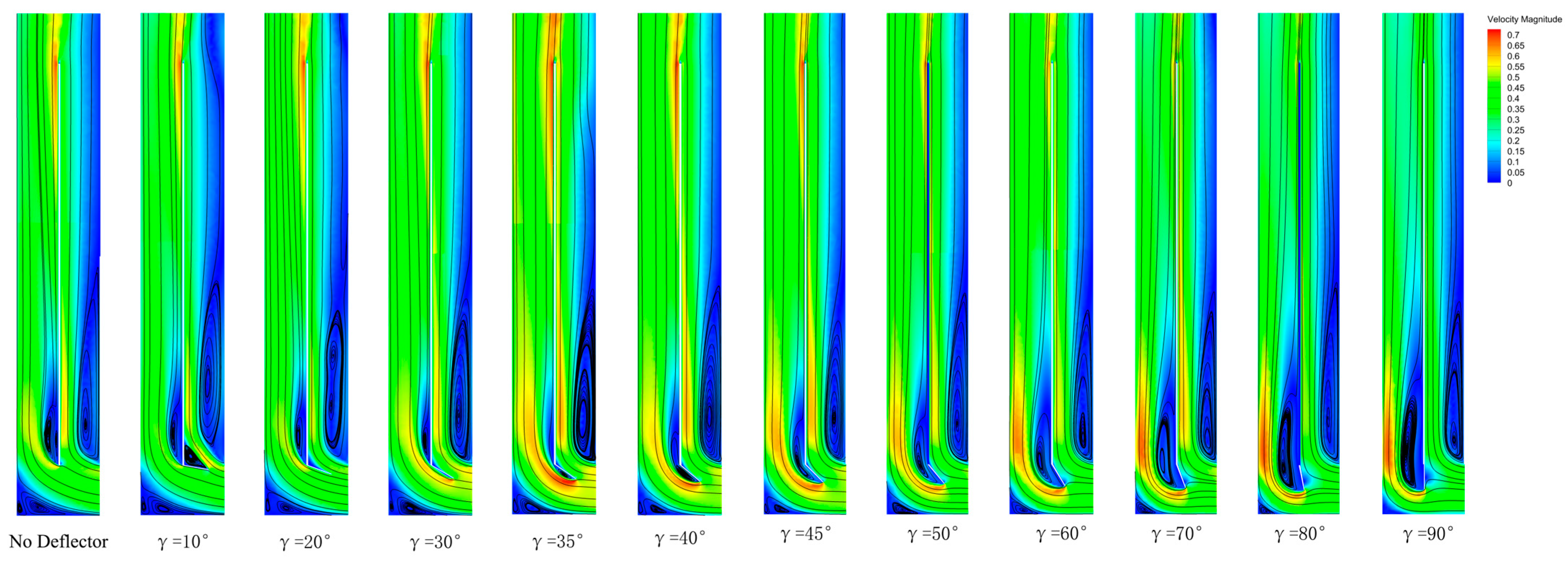
4.2.3. Analysis of Vortex Area in the Chimney

Figure 18 illustrates the evolution of vortex areas with varying deflector angles. As illustrated, the vortex area in the inner channel progressively diminishes with the increasing deflector angle γ relative to the horizontal plane. However, when γ ≥ 35°, the outer-channel vortex zone begins to expand incrementally, impairing coherent outer-channel airflow.
Figure 19 demonstrates the variation in the relative vortex area ratio P (defined as P = S0/S, where S0 is the vortex zone area and S is the cross-sectional area of the solar chimney channel) with the deflector angle. As shown in Figure 19, the optimized solar chimney exhibited consistently lower relative vortex area ratios compared with the conventional design. The vortex area demonstrated a non-monotonic variation with the increasing deflector angle, initially decreasing before subsequently increasing. The minimum vortex area ratio occurred at γ = 35°, representing a 31% reduction relative to the deflector-free configuration. At this optimal angle, outer-channel vortices were concentrated beneath the deflector (Figure 18), significantly expanding the heat exchange area between airflow and the absorber plate, thereby maximizing thermal performance. For deflector angles γ ≤ 20°, while vortex area ratios remained lower than those in conventional chimneys, the deflector obstructed airflow entry into the inner channel, reducing the thermal mass flow interacting with the absorber plate and ultimately diminishing the overall ventilation rate. At angles γ ≥ 50°, despite maintaining lower vortex area ratios than the baseline, ventilation performance still deteriorated. This paradox arises from competing effects; the progressive shrinkage of outer-channel inlet dimensions limits airflow capacity, while the dominance of outer-channel thermal driving forces creates an imbalanced energy distribution.

4.3. Conditions for the Ventilation Performance of the Optimized Double-Channel Solar Chimney

Based on the analysis of the impacts of deflector length and angle on the ventilation performance of the solar chimney, the optimal installation conditions were determined as a deflector angle of γ = 35° and a dimensionless deflector length of l/D = 0.3. To evaluate the natural ventilation capacity of both optimized and conventional dual-channel solar chimneys in real-world applications, transient numerical simulations were conducted using ANSYS Fluent under steady-state boundary conditions. For optimal solar gain, double-channel solar chimneys are typically installed on the south-facing façades of buildings. The simulations were geographically localized to Hangzhou, China, and temporally focused on daylight hours (7:00–18:00) on 21 March 2024, to capture diurnal solar variations.
Figure 20 illustrates the ventilation rates of both dual-channel solar chimney configurations during operation, with the optimized design consistently outperforming the conventional system at all measured intervals. The optimized chimney achieved ventilation rates exceeding those of the conventional design by ≥5% throughout the operational period. At 13:00, when solar irradiance peaked at 800 W/m2, the optimized system reached a ventilation rate of 0.185 kg/s, representing an 8.2% improvement over the conventional system’s peak value of 0.171 kg/s.
The thermal efficiency comparisons in Figure 21 reveal analogous trends. The optimized design maintains a thermal efficiency advantage of ≥3.5% across all timepoints, peaking at 41.2% under maximum solar radiation. This performance represents a 7.5% enhancement compared with the conventional system’s peak efficiency of 38.3%, demonstrating significant synergies between aerodynamic optimization and utilization of thermal energy.

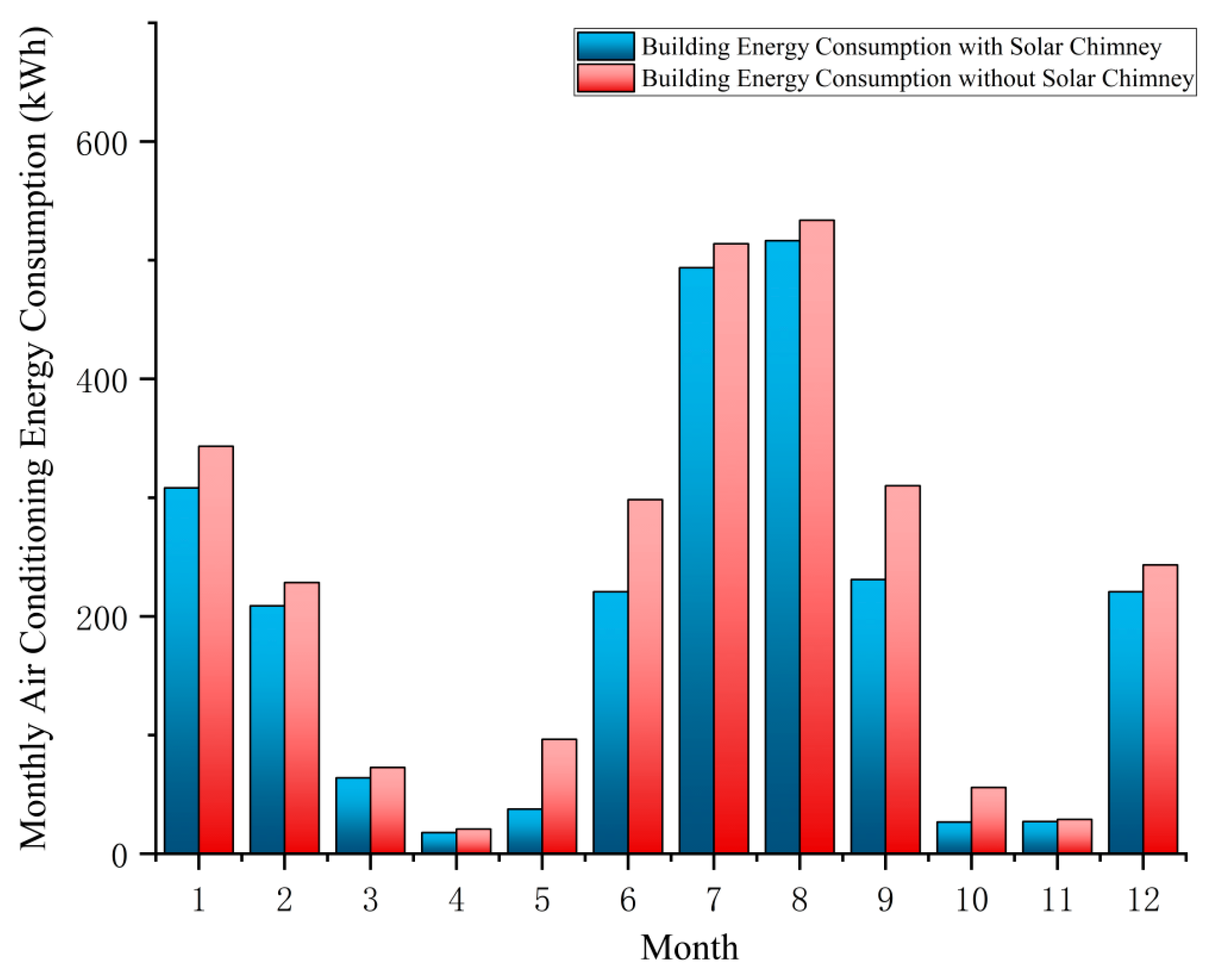
4.4. Energy-Saving Potential of the Optimized Double-Channel Solar Chimney

Dual-channel solar chimneys enhance indoor ventilation and reduce energy consumption in ventilation mode, while improving thermal circulation and increasing the thermal resistance of building envelopes in insulation mode, thereby minimizing heat loss and achieving energy efficiency [26]. To facilitate the evaluation of the impact of the optimized dual-channel solar chimney on the building’s air conditioning energy consumption, two operating conditions were established. The operating solar chimney conditions included an outdoor temperature between 18 °C and 26 °C, when the solar chimney was automatically turned on, with the chimney turned off at all other times. Conditions without an operating solar chimney were when the building was equipped with a solar chimney that remained in the off state at all times. The monthly air conditioning energy consumption of the building with or without the operation of the double-channel solar chimney is shown in Figure 22. The comparison of energy consumption before and after the operation of the solar chimney in different months is shown in Table 4. The air conditioning energy consumption of the building without using the solar chimney throughout the year is 2745.6 kWh. With the use of the solar chimney, the air conditioning energy consumption of the building is reduced to 2373.3 kWh, resulting in a total energy saving of 372.3 kWh and a 13.6% reduction in energy consumption. Under these conditions, the cooling energy consumption decreases from 1829 kWh to 1572 kWh, with a cooling-season energy-saving rate of 16.4%. The heating energy consumption decreases from 916 kWh to 868 kWh, with a heating energy-saving rate of 5.5%. It is evident that in Hangzhou, a region with hot summers and cold winters, solar chimneys can have a significant effect on buildings’ energy savings. Particularly in transitional seasons, the energy-saving potential of solar chimneys is especially notable. In April, May, June, September, October, and November, the energy-saving rates are 13.9%, 60.9%, 26%, 25.4%, 51.9%, and 23.2%, respectively. The operation of the double-channel solar chimney not only provides additional passive cooling and heating for the building but also significantly reduces the air conditioning load through natural ventilation. During the winter, the double-channel solar chimney can be set to insulation mode (with upper and lower openings on the interior walls) to reduce the heating load of the air conditioning to a certain extent through indoor heat circulation. The energy-saving rates in January, February, and December are 10.2%, 8.5%, and 9.2%, respectively.
Thus, it is evident that the solar chimney has a significant effect on building energy savings in Hangzhou, particularly in transitional seasons. The energy-saving potential of the double-channel solar chimney is particularly outstanding.

5. Conclusions

To quantify the optimization potential of deflector installation parameters on the ventilation performance of double-channel solar chimneys, this study integrated experimental measurements with CFD simulations, establishing a numerical validation framework based on the k-epsilon model. Although localized velocity deviations arose due to factors such as material surface roughness, the experimental data and CFD results showed good overall agreement, confirming the method’s efficacy in characterizing the impact mechanisms of deflector angle (γ) and length (l/D) on chimney performance. Furthermore, orthogonal experimental design was employed to conduct parametric analyses of flow field characteristics across varying angles and lengths.
  • Numerical simulations revealed that the ventilation performance of double-channel solar chimneys exhibits a non-monotonic trend with increasing deflector length (l/D), characterized by an initial enhancement followed by a decline. An appropriately sized deflector can optimize the streamlined structure, preventing vortices caused by sudden changes in cross-section. However, an excessively long deflector may increase local energy loss. The optimal performance was achieved when the deflector length reached l/D = 0.3. At this configuration, the ventilation rate increased by 5.59% and the thermal efficiency improved by 3.8% compared with the baseline design (without deflectors).
  • The deflector inclination angle relative to the horizontal plane critically determines system performance. Empirical results demonstrate that deflector angles within 30° ≤ γ ≤ 80° universally enhance ventilation performance compared with conventional dual-channel solar chimneys. A properly angled deflector can precisely direct the airflow, preventing turbulence or recirculation zones, thereby improving the uniformity of airflow distribution. The γ = 35° configuration achieved peak optimization with improvements of 6.8% and 4.4%, respectively, over baseline values.
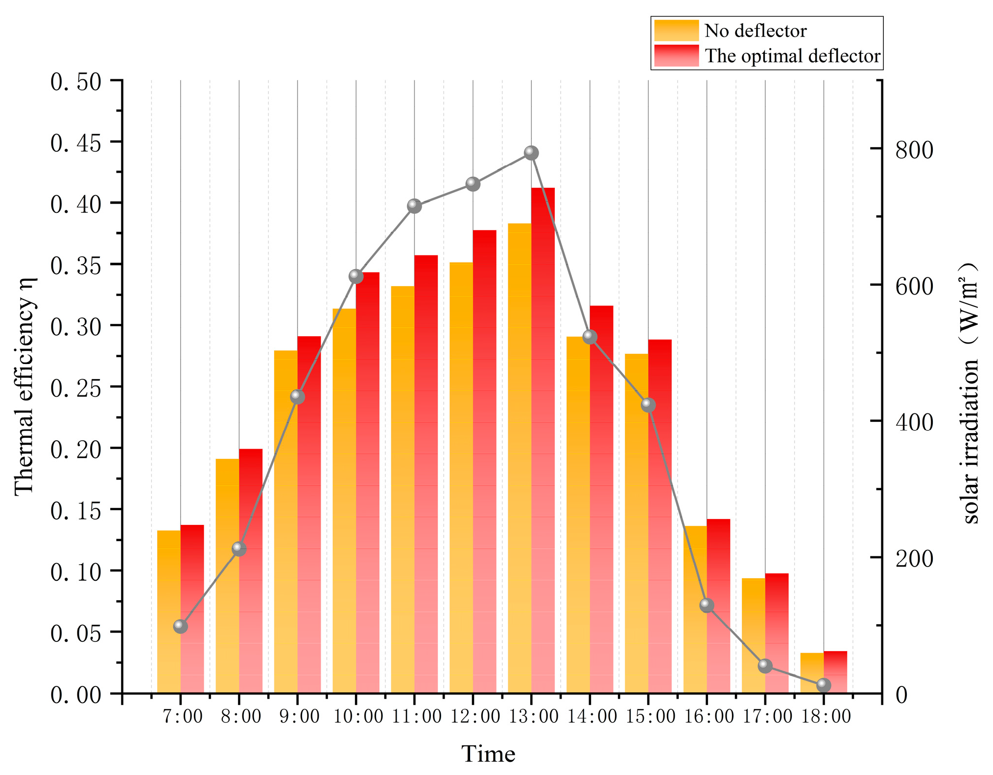
  • The optimal installation conditions for the deflector in the optimized double-channel solar chimney are a deflector angle to the horizontal of γ = 35° and a length-to-diameter ratio l/D = 0.3. These conditions were applied in the building ventilation simulations, and at all times during operation, the ventilation performance of the optimized double-channel solar chimney was significantly better than that of the traditional solar chimney. Particularly at 13:00, under peak solar irradiance (800 W/m2), the ventilation rate of the optimized double-channel solar chimney reached up to 0.185 kg/s, an 8.8% improvement compared with the unoptimized conditions. The thermal efficiency reached 40.2%, an increase of 6.08%.
  • The building’s total annual energy consumption with the application of the optimized double-channel solar chimney was reduced by 13.6% compared with conventional designs. The energy-saving potential of the optimized double-channel solar chimney is especially significant during transitional seasons, with energy-saving rates reaching as high as 60.9% in May and 51.9% in October.
Through this study, we propose optimal installation conditions for deflectors in dual-channel solar chimneys. The optimized system demonstrates enhanced ventilation and thermal efficiency, achieving an energy saving rate of 13.6%. Future research should explore optimizing deflector quantity (e.g., two deflectors in channel) and seasonal ventilation modes (summer cooling or winter heat recovery) to further refine installation criteria.

Author Contributions

Conceptualization, G.Z.; Methodology, Y.Z. and G.Z.; Software, Q.L.; Validation, Z.C.; Formal analysis, C.Y.; Investigation, C.Y.; Resources, X.L; Data curation, X.L.; Writing—original draft preparation, C.Y.; Writing—review & editing, Z.C. and G.Z.; Visualization, S.L.; Supervision, G.Z.; Project administration, Z.C.; Funding acquisition, Z.C. All authors have read and agreed to the published version of the manuscript.

Funding

This research was funded by the National Natural Science Foundation of China (Grant No. 52108257). The APCwas funded by the Natural Science Foundation of Zhejiang Province (Grant No. LTGS24E080006).

Data Availability Statement

The data that support the findings of this study are available from the corresponding author upon reasonable request.

Conflicts of Interest

Author Xiaojun Luo was employed by the company China Construction Fifth Engineering Division Co., Ltd., Hangzhou 311300, China. The remaining authors declare that the research was conducted in the absence of any commercial or financial relationships that could be construed as a potential conflict of interest.

Nomenclature

The following nomenclature is used in this manuscript:
k Turbulent pulsation kinetic energy (J)
μ eff Fluid effective dynamic viscosity kg/(s·m)
ρ Air density (kg/m3)
ε Dissipation rate of turbulent pulsating momentum
α ε Reciprocal of the effective Prandtl number ε
u x Velocity of fluid in the x direction (m/s)
u y Velocity of fluid in the y direction (m/s)
u z Velocity of fluid in the z direction (m/s)
T 0 Initial temperature (K)
C 1 ε Calculation constant
C 2 ε Calculation constant
C k Turbulent kinetic energy due to mean velocity gradient (J)
γDeflector angle (°)
lLength of deflector (m)
DDepth of solar chimney (m)
HHeight of solar chimney (m)
LWidth of solar chimney (m)
l1 Length of solar collector (m)
L1Width of solar collector (m)

References

  1. Liu, Z.; Zhang, L.; Gong, G.; Li, H.; Tang, G. Review of solar thermoelectric cooling technologies for use in zero energy buildings. Energy Build. 2015, 102, 207–216. [Google Scholar] [CrossRef]
  2. Lotfabadi, P. Analyzing passive solar strategies in the case of high-rise building. Renew. Sustain. Energy Rev. 2015, 52, 1340–1353. [Google Scholar] [CrossRef]
  3. Fang, X.; Li, Y. Numerical simulation and sensitivity analysis of lattice passive solar heating walls. Sol. Energy 2000, 69, 55–66. [Google Scholar] [CrossRef]
  4. Zhai, X.; Song, Z.; Wang, R. A review for the applications of solar chimneys in buildings. Renew. Sustain. Energy Rev. 2011, 15, 3757–3767. [Google Scholar] [CrossRef]
  5. Khedari, J.; Rachapradit, N.; Hirunlabh, J. Field study of performance of solar chimney with air-conditioned building. Energy 2003, 28, 1099–1114. [Google Scholar] [CrossRef]
  6. Agarwal, S.; Batista, R. Enhancement of building thermal performance: A comparative analysis of integrated solar chimney and geothermal systems. J. Sustain. Energy 2023, 2, 91–108. [Google Scholar] [CrossRef]
  7. Shi, L.; Zhang, G.; Yang, W.; Huang, D.; Cheng, X.; Setunge, S. Determining the influencing factors on the performance of solar chimney in buildings. Renew. Sustain. Energy Rev. 2018, 88, 223–238. [Google Scholar] [CrossRef]
  8. Hosien, M.; Selim, S. Effects of the geometrical and operational parameters and alternative outer cover materials on the performance of solar chimney used for natural ventilation. Energy Build. 2017, 138, 355–367. [Google Scholar] [CrossRef]
  9. Xu, X.W.; Su, Y.X. Modeling of natural ventilation in built-in photovoltaic-Trombe wall. Appl. Mech. Mater. 2014, 448, 1537–1541. [Google Scholar] [CrossRef]
  10. Zalewski, L.; Lassue, S.; Duthoit, B.; Butez, M. Study of solar walls—Validating a simulation model. Build. Environ. 2002, 37, 109–121. [Google Scholar] [CrossRef]
  11. Lee, K.H.; Strand, R.K. Enhancement of natural ventilation in buildings using a thermal chimney. Energy Build. 2009, 41, 615–621. [Google Scholar] [CrossRef]
  12. Zhang, L.; Dong, J.; Sun, S.; Chen, Z. Numerical simulation and sensitivity analysis on an improved Trombe wall. Sustain. Energy Technol. Assess. 2021, 43, 100941. [Google Scholar] [CrossRef]
  13. Imran, A.A.; Jalil, J.M.; Ahmed, S.T. Induced flow for ventilation and cooling by a solar chimney. Renew. Energy 2015, 78, 236–244. [Google Scholar] [CrossRef]
  14. Bassiouny, R.; Koura, N.S. An analytical and numerical study of solar chimney use for room natural ventilation. Energy Build. 2008, 40, 865–873. [Google Scholar] [CrossRef]
  15. Han, M.; Cui, H.; Han, Z.; Liu, Q. Research on the new passive optimization strategies for improving the performance of combined solar chimney. Energy Build. 2024, 320, 114578. [Google Scholar] [CrossRef]
  16. Arce, J.; Xamán, J.; Alvarez, G.; Jiménez, M.; Guzmán, J.; Heras, M. Theoretical study on a diurnal solar chimney with double air flow. In Proceedings of the 1st International Conference on Solar Heating, Cooling and Buildings (EUROSUN), Sociedade Portuguesa de Energia Solar (SPES), Lisbon, Portugal, 7–10 October 2008; pp. 7–10. [Google Scholar]
  17. Vargas-López, R.; Xamán, J.; Hernández-Pérez, I.; Arce, J.; Zavala-Guillén, I.; Jiménez, M.; Heras, M. Mathematical models of solar chimneys with a phase change material for ventilation of buildings: A review using global energy balance. Energy 2019, 170, 683–708. [Google Scholar] [CrossRef]
  18. Zavala-Guillén, I.; Xamán, J.; Álvarez, G.; Arce, J.; Hernández-Pérez, I.; Gijón-Rivera, M. Computational fluid dynamics for modeling the turbulent natural convection in a double air-channel solar chimney system. Int. J. Mod. Phys. C 2016, 27, 1650095. [Google Scholar] [CrossRef]
  19. Lei, Y.; Zhang, Y.; Wang, F.; Wang, X. Enhancement of natural ventilation of a novel roof solar chimney with perforated absorber plate for building energy conservation. Appl. Therm. Eng. 2016, 107, 653–661. [Google Scholar] [CrossRef]
  20. Fang, Z.; Wang, W.; Chen, Y.; Song, J. Structural and heat transfer model analysis of wall-mounted solar chimney inlets and outlets in single-story buildings. Buildings 2022, 12, 1790. [Google Scholar] [CrossRef]
  21. Gowda, B.K.; Rajagopal, M.; Seetharamu, K. Heat transfer in a side heated trapezoidal cavity with openings. Eng. Sci. Technol. Int. J. 2019, 22, 153–167. [Google Scholar] [CrossRef]
  22. Zhou, Y.; Wang, Z.; Xu, L.; Zhang, S.; Sui, C. Characteristic analysis of buoyancy induced indoor ventilation in Trombe wall channels. Acta Energiae Solaris Sin. 2021, 42, 176–183. [Google Scholar]
  23. Mandal, D.K.; Pradhan, S.; Chakraborty, R.; Barman, A.; Biswas, N. Experimental investigation of a solar chimney power plant and its numerical verification of thermo-physical flow parameters for performance enhancement. Sustain. Energy Technol. Assess. 2022, 50, 101786. [Google Scholar]
  24. Sheng, Z.; Zhang, G.; Luo, X.; Ye, C.; Lin, J.; Chen, Z. Research Optimizing Building Ventilation Performance through the Application of Trombe Walls in Regions with Hot Summers and Cold Winters: A Case Study in China. Sustainability 2024, 16, 3107. [Google Scholar] [CrossRef]
  25. Gong, J.; Cheng, K.X.; Liu, H.; Chew, L.W.; Lee, P.S. A novel staggered split absorber design for enhanced solar chimney performance. Build. Environ. 2022, 224, 109569. [Google Scholar] [CrossRef]
  26. Omle, I.; Kovács, E.; Bolló, B. Applying recent efficient numerical methods for long-term simulations of heat transfer in walls to optimize thermal insulation. Results Eng. 2023, 20, 101476. [Google Scholar] [CrossRef]
Figure 1. Technical route (created by the authors).
Buildings 15 01380 g001
Figure 2. Schematic diagram of the solar chimney (created by the authors).
Buildings 15 01380 g002
Figure 3. The meshing of the physical model (illustration created by the authors).
Buildings 15 01380 g003
Figure 4. Calculated ventilation under different numbers of grids (diagram created by the authors).
Buildings 15 01380 g004
Figure 5. Schematic of the double-channel solar chimney created by the authors.
Buildings 15 01380 g005
Figure 6. Constructed prototype of the double-channel solar chimney created by the authors.
Buildings 15 01380 g006
Figure 7. Diurnal variations in outlet airflow velocity and solar radiation intensity for the experimental setup (graph created by the authors).
Buildings 15 01380 g007
Figure 8. Comparison of computed and measured velocity (graph created by the authors).
Buildings 15 01380 g008
Figure 9. Comparison between experimental results and numerical results for volumetric flow rate at various air gap sizes under 300 W/m2 (graph created by the authors).
Buildings 15 01380 g009
Figure 10. The velocity contours and streamline distributions of double-channel solar chimneys with different deflector lengths (images created by the authors).
Buildings 15 01380 g010
Figure 11. Variation in ventilation with deflector length (chart created by the authors).
Buildings 15 01380 g011
Figure 12. Variation in thermal efficiency with deflector length (chart created by the authors).
Buildings 15 01380 g012
Figure 13. Variation in relative vortex area ratio P with deflector length (chart created by the authors).
Buildings 15 01380 g013
Figure 14. Vortex region in solar chimney with varying deflector lengths (images created by the authors).
Buildings 15 01380 g014
Figure 15. The velocity contours and streamline distributions of double-channel solar chimneys with different deflector angles (images created by the authors).
Buildings 15 01380 g015
Figure 16. Variation in ventilation with deflector angle (γ) (graph created by the authors).
Buildings 15 01380 g016
Figure 17. Variation in thermal efficiency with deflector angle (γ) (graph created by the authors).
Buildings 15 01380 g017
Figure 18. Vortex regions in a solar chimney with varying deflector angles (images created by the authors).
Buildings 15 01380 g018
Figure 19. Variation in relative vortex area ratio P with deflector angle (graph created by the authors).
Buildings 15 01380 g019
Figure 20. Variations in ventilation during operation of dual-channel solar chimneys (graph created by the authors).
Buildings 15 01380 g020
Figure 21. Thermal efficiency during operation of dual-channel solar chimneys (graph created by the authors).
Buildings 15 01380 g021
Figure 22. The monthly air conditioning energy consumption of the building with or without the operation of the double-channel solar chimney (graph created by the authors).
Buildings 15 01380 g022
Table 1. Material property parameters (table created by the authors).
NameDensity
(kg/m3)
Specific Heat
(J/(kg∙K))
Thermal Conductivity
(W/(m∙K))
AbsorptionTransmittanceMaterial
Window25008400.750.060.84Glass
Insulation wall18008790.814//Concrete
Solar collector2719871202.40.95/Aluminum alloy
Table 2. Thermophysical properties parameters of air (table created by the authors).
Density
(kg/m3)
Specific Heat
(J/(kg∙K))
Thermal Conductivity
(W/(m∙K))
Viscosity Coefficient
(kg/(m∙s))
Coefficient of Thermal Expansion(1/K)
1.2051005.430.2591.81 × 10−50.0034
Table 3. Introduction to testing instruments and measurement parameters (table created by the authors).
Instrument Name and ModelMeasured ParametersInstrument Accuracy and Testing Range
Ruiyika solar pyranometer (China)Solar radiation on the solar chimneySpectral range: 300–3200 nm;
Measurement range: 0–2000 W/m2;
Response time: ≤20 s (99% response);
Internal resistance:350 Ω;
Cosine response: ≤±7% (at solar altitude angle = 10°);
Temperature dependence: ±2% (−10 + 40 °C);
Sensitivity: 7–14 μV·W⁻1·m2;
Nonlinearity: ±2%;
Measurement accuracy: ≤5%.
Biaozhi GM8903 thermal anemometer (China)Airflow velocity at the outlet measurement pointsWind speed measurement range: 0–30 m/s;
Resolution: 0.001 m/s;
Accuracy: ±3%.
Aluminum alloy sheet/400 mm × 800 mm × 3 mm
Plywood panel/1000 mm × 300 mm × 2 mm × 2; 400 mm × 300 mm × 2 mm; 400 mm × 900 mm × 2 mm
Acrylic panel/1000 mm × 400 mm × 2 mm; Transmittance: 92%
Table 4. Energy Consumption Comparison Before and After the Operation of the Solar Chimney in Different Months (table created by the authors).
MonthAC Energy (No Solar Chimney) (kWh)AC Energy (with Solar Chimney) (kWh)Energy Saved (kWh)Efficiency Gain (%)
January343.4308.335.110.2
February228.4208.819.68.5
March72.763.98.812.1
April20.817.92.913.9
May96.537.758.860.9
June298.4220.777.726
July513.9493.820.13.9
August533.7516.517.23.2
September310231.178.925.4
October55.726.828.951.9
November28.822.16.723.2
December243.3220.722.69.2
Year2745.62373.3372.313.6
Disclaimer/Publisher’s Note: The statements, opinions and data contained in all publications are solely those of the individual author(s) and contributor(s) and not of MDPI and/or the editor(s). MDPI and/or the editor(s) disclaim responsibility for any injury to people or property resulting from any ideas, methods, instructions or products referred to in the content.

