Article

Research on the Reinforcement Design of Concrete Deep Beams with Openings Based on the Strut-and-Tie Model

1
Shandong Key Laboratory of Civil Engineering Disaster Prevention and Mitigation, Shandong University of Science and Technology, Qingdao 266590, China
2
College of Civil Engineering and Architecture, Shandong University of Science and Technology, Qingdao 266590, China
3
Key Laboratory of Concrete and Pre-Stressed Concrete Structures of Ministry of Education, Southeast University, Nanjing 211189, China
*
Author to whom correspondence should be addressed.
Buildings 2025, 15(8), 1382; https://doi.org/10.3390/buildings15081382
Submission received: 10 March 2025 / Revised: 10 April 2025 / Accepted: 15 April 2025 / Published: 21 April 2025
(This article belongs to the Section Building Structures)

Abstract

:
This study investigates the issues of non-unique model configurations and insufficient guidance for reinforcement design encountered when applying the strut-and-tie model (STM) method to reinforced concrete deep beams with openings. Using concrete deep beam specimens with three openings as a case study, the topology optimization method was employed to establish the initial STM, which was subsequently refined through crack propagation simulation technology to develop the final optimized STM for guiding reinforcement design. Experimental investigations and comparative analyses with existing literature demonstrate that the proposed approach offers significant advantages in controlling initial concrete cracking, improving structural load-bearing capacity, and reducing steel reinforcement consumption for such perforated deep beams designed with this optimized STM methodology.

1. Introduction

The reinforcement design of concrete beams is crucial for ensuring their mechanical performance, deformation capacity, and economic rationality [1,2]. Although concrete deep beams possess high load-bearing capacity, the openings are usually required to meet architectural functional requirements (such as door and window openings) and the installation of equipment and utility pipelines [3,4]. The stress situation of concrete deep beams with openings under vertical loads is more complicated, and the mechanical property and failure modes are quite different from those of ordinary concrete shallow beams, especially in the regions where the geometric shape changes suddenly, where the load (support) acts, or where the force flow distribution is in relatively disturbed regions (D-regions) [5,6]. Therefore, traditional cross-section analysis methods are not suitable for the reinforcement design of concrete deep beams with openings, necessitating the development of a scientifically sound, economically practical, and technically feasible design approach [7]. The research by Can MENG et al. [8] indicates that, compared to the design method specified in the Chinese code for concrete structures [9], the strut-and-tie model (STM) approach for designing irregular-shaped concrete deep beams can reduce steel reinforcement consumption by 15–20% while increasing the load-bearing capacity by over 20% and improving the ultimate deformation capacity by approximately 30%.
The STM, a truss-analogous model simplified from the internal force transfer paths within structural members, is utilized in the design process through calculations and structural checks to achieve reinforcement design, a method referred to as the STM design method [10]. However, determining the STM configuration of the irregular concrete deep beam is the primary task of related design using the STM design method. An accurate and reasonable STM can not only vividly describe the load-transfer path inside the irregular concrete deep beam but also can better guide the reinforcement design [11]. A robust STM must not only accurately reflect the force transfer mechanism within the structural member but also effectively guide reinforcement design. Therefore, establishing an accurate and rational STM constitutes the primary task in the reinforcement design of concrete deep beams with openings.
Imad Shakir Abbood [12] suggests that there is still no unified strut-and-tie model (STM) for designing the same type of reinforced concrete deep beams, making the selection of an appropriate STM a challenging task for designers. Although current design codes allow for effective design using the STM method, additional experimental work is necessary to verify that concrete deep beams achieve a sufficient safety level. Moreover, research on the post-cracking serviceability performance of RC deep beams based on improved STM approaches remains limited.
The complex nonlinear stress–strain behavior in concrete deep beams with openings leads to significant challenges in traditional STM construction [13]. These conventional methods demand higher levels of designer expertise, heavily rely on subjective empirical judgment, and suffer from low computational efficiency. In response, some researchers have begun exploring topology optimization techniques to develop rationalized STM configurations [14]. Yang et al. [15] proposed a bi-directional evolutionary structural optimization (BESO) method that can delete and add elements simultaneously in the process of topology optimization. Xia et al. [16] proposed a topology optimization result evaluation method for constructing an STM by the topology optimization method. However, this method does not consider the details of the reinforcement design, the minimum reinforcement ratio, and the constructability of the reinforcement design.
Currently, the reinforcement design methodology for concrete deep beams based on the STM remains unstandardized, particularly in terms of STM configuration and its application in guiding reinforcement design. Mohamed E. El-Zoughiby et al. [17] proposed a generalized strut-and-tie model (STM) for reinforced concrete coupling beams (or link beams) with high shear capacity demands. They provided corresponding calculation methods and design procedures, but this approach requires the selection of relevant parameters based on the beam’s span-to-depth ratio, concrete strength, and shear demand. Yuhan Nie et al. [18] proposed a practical design method for establishing a simplified STM based on topology optimization. The method was validated through experiments and finite element simulations on corbel specimens with irregular geometries and complex stress distributions. The results demonstrated that, compared to the original model, this approach reduced the maximum horizontal displacement by 72% and significantly decreased the maximum vertical displacement by 80%. However, the optimization of the STM requires careful consideration of the intricate stress trajectories in the corbel structure.
Based on previous research [19,20], this study addresses the current challenges in strut-and-tie model (STM) design for reinforced concrete deep beams with openings, including difficulties in STM construction, non-unique configurations, and poor guidance for reinforcement design. Focusing on a reinforced concrete deep beam with three openings subjected to three concentrated loads, the research improves and experimentally investigates the process and methodology of constructing an STM using topology optimization. By comparing and analyzing results from the existing literature and experimental data in this study, the effectiveness of the proposed STM construction method is validated. The findings provide valuable insights and a scientific basis for the future STM-based reinforcement design of perforated concrete deep beams.

2. Construction of the STM

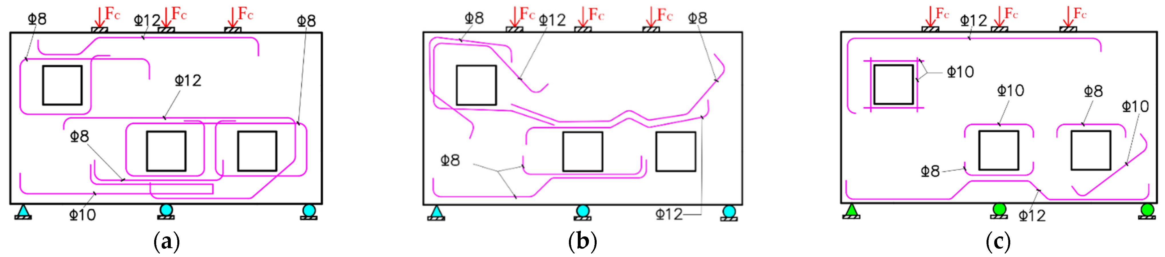
2.1. Specimen Design

The geometric configuration, boundary conditions, and loading scenarios of the concrete deep beams with openings are illustrated in Figure 1. In Figure 1, the design load FC = 50 kN, and the specimen thickness is 65 mm.

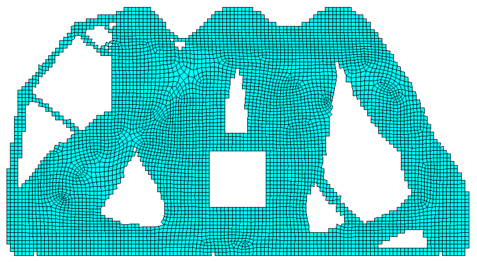
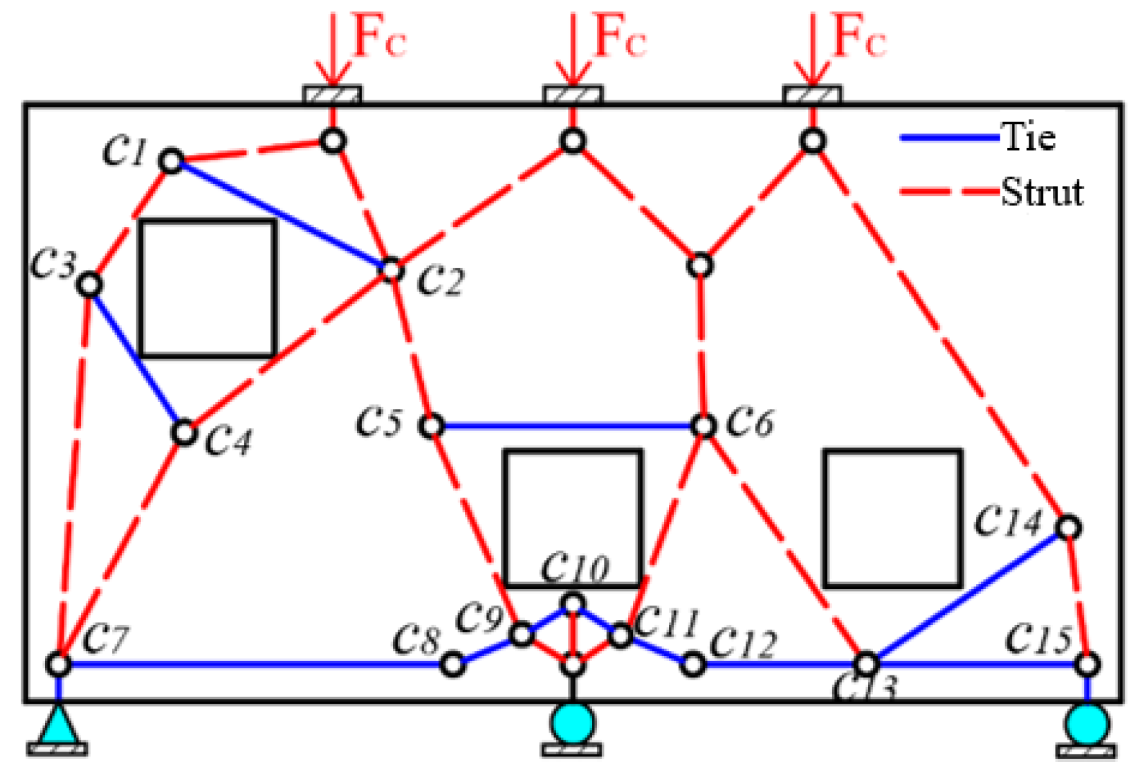
2.2. Topology Optimization and Initial STM

The finite element model of this type of concrete deep beam specimen was developed using ANSYS 14.5 software and subjected to topology optimization through the BESO method [21]. The optimized topology configuration is illustrated in Figure 2, with the stress contour plot shown in Figure 3. In Figure 3, the solid lines represent dominant tensile stress transfer paths (ties), while dashed lines indicate principal compressive stress transfer paths (struts). The initial STM constructed based on the topology optimization results for this category of concrete deep beam specimen is presented in Figure 4. To facilitate comparative analysis in subsequent sections, the nodes in the strut-and-tie model shown in Figure 4 are labeled using a combination of letter and number. The material property indices were calculated and determined with reference to the study by Resmy V.R. and Musab Rabi et al. [22,23,24], while the topology optimization parameters are presented in Table 1.

2.3. Crack Propagation Simulation and Optimization of the STM

The initial STM constructed by the topology optimization method (Figure 4) can fully reflect the load-transmission mechanism of the concrete deep beam specimen, but the members in the model are mostly oblique and intensive, resulting in difficulty in the calculation of the model in the later period, and it cannot guide the actual reinforcement design [12]. Therefore, the concrete crack propagation simulation technology was introduced, and the positions of the members in the initial STM were adjusted according to the internal relationship between the crack propagation of the specimen and its load-transfer mechanism so as to realize the optimization of the initial STM in order to obtain an accurate and reasonable optimal STM to guide the reinforcement design.

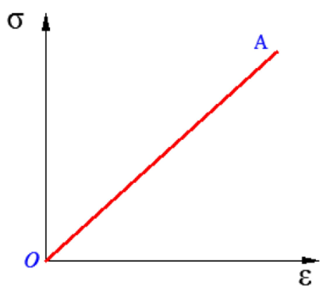
2.3.1. Concrete Crack Propagation Simulation

In order to more realistically simulate the crack shape of this type of concrete deep beam under the load and effectively identify its weak areas (the position and direction of the cracks), the concrete random aggregate model (RAM) [25] was used in the simulation process of the concrete deep beam crack propagation. The RAM assumes that concrete is a three-phase component heterogeneous composite material composed of an aggregate, cement mortar, and the interfacial transition zone (ITZ) between the aggregate and cement mortar. With the aid of the aggregate grading curve given by J. C. Walraven [26], the actual number of aggregate particles was determined, and the Monte Carlo method [27] was used to randomly generate an aggregate distribution model within the specimen. The mechanical properties of each phase component material conform to the Weibull distribution [28], as shown in Figure 5.
During the simulation of crack propagation, it is assumed that the concrete aggregate is always in an elastic state, and the components of the cement mortar and the ITZ follow the three-fold line constitutive model. The constitutive equations of the cement mortar and ITZ can be shown in Equation (1) and Equation (2), respectively. The constitutive relationship of the concrete aggregates was assumed as shown in Figure 6, while other material property indices of concrete were calculated and determined with reference to the study by Al-Kheetan M.J. [29] and Rabee Shamass et al. [30].
σ cem = { f cem t ε cem t ε cem 0 ε cem ε cem t f cem m f cem t ε cem m ε cem t ( ε cem ε cem t ) + f cem t ε cem t ε cem ε cem m f cem f f cem m ε cem f ε cem m ( ε cem ε cem m ) + f cem m ε cem m ε cem ε cem f C min * ε cem f ε cem
σ itz = { f itz t ε itz t ε itz 0 ε itz ε itz t f itz m f itz t ε itz m ε itz t ( ε itz ε itz t ) + f itz t ε itz t ε itz ε itz m f itz f f itz m ε itz f ε itz m ( ε itz ε itz m ) + f itz m ε itz m ε itz ε itz f C min * ε itz f ε itz
where ftcem and ftitz are the initial tensile strength of the concrete cement mortar and ITZ, respectively; εtcem and εtitz are the principal tensile strains corresponding to ftcem and ftitz; fmcem and fmitz are the residual tensile strengths of the cement mortar and ITZ, respectively; εmcem and εmitz are the principal tensile strains corresponding to fmcem and fmitz; εfcem, εfitz are the ultimate tensile strain at which the cement mortar and ITZ completely lose the tensile strength, respectively; and C*min represents a minimum value (such as 1 × 10⁻⁵).
The crack propagation simulation results of the specimen can be obtained by executing the concrete crack propagation simulation program, as shown in Figure 7. The numbers in the subscripts of Cr1 and Cr2 indicate the order of the crack appearance, and the direction of the red arrow indicates the direction of crack propagation. The color of the figure is to clearly and intuitively display the crack shape and has no practical significance.

2.3.2. Optimization of STM

The propagation of concrete cracks is intrinsically linked to the load-transfer mechanism and failure modes of structural members. The failure of concrete material primarily occurs when its tensile stress reaches a critical threshold, causing cracks to propagate perpendicular to the direction of the principal tensile stress. Therefore, the initial strut-and-tie model (STM) can be optimized by adjusting the tie positions based on the correlation between crack propagation and load-transfer behavior, ultimately yielding an optimal STM for reinforcement design guidance.
First, the weak regions of the structural member under load must be identified to guide adjustments of members in the strut-and-tie model. These weak regions were determined based on information such as crack initiation locations, propagation directions, and crack lengths. Second, members within these weak regions, referred to as key members, correspond to critical load-bearing reinforcement in the design. They govern the mechanical behavior and failure modes of the member and require prioritized optimization. Since concrete is prone to tensile cracking, particular attention should be paid to optimizing tie members during adjustments. As crack propagation aligns perpendicular to principal tensile stresses, the optimal orientation of tie members in key regions should be perpendicular to the primary crack direction. This configuration maximizes the utilization of steel reinforcement’s tensile resistance, ensuring cost-effective and rational reinforcement design. Finally, during adjustments of key members, connected or adjacent members should be merged or substituted to simplify the strut-and-tie model and enhance its practical applicability. To strengthen the restraining effect on primary cracks in weak regions, ties should be preferentially positioned at crack initiation points. Additionally, to accommodate constructability requirements, tie members should ideally align with the main boundaries of concrete elements or be arranged as orthogonal members.
Based on the crack propagation simulation results of this category of the concrete deep beam specimen (Figure 7), the regions corresponding to the two dominant cracks (Cr1 and Cr2) are identified as critical weak zones. Consequently, the ties within these weak zones in the initial STM configuration (Figure 4) require prioritized refinement during the model optimization process.
Based on the aforementioned optimization principles for the STM members, integrated with the stress distribution illustrated in Figure 3 and constructability considerations for reinforcement design, the optimized configuration of the initial STM is presented in Figure 8 and designated as STM-04. Key modifications include the following: ① To align with the location and propagation direction of dominant crack Cr1 (Figure 7), the original member c5c6 (Figure 4) is horizontally extended to the right opening, forming the optimized tie C5C6 in Figure 8; ② addressing crack Cr2’s trajectory, members c9c10 and c10c11 from Figure 4 are merged and reoriented perpendicular to crack Cr2’s path while positioned at its initiation zone, achieving both mechanical efficacy and construction feasibility (member C9C11 in Figure 8); ③ to mitigate stress concentration at the loading point and constrain crack Cr1’s propagation, this additional member is strategically placed to enhance the load-transfer efficiency (the member C16C17 in Figure 8); ④ original members c1c2 and c3c4 (Figure 4) are reconfigured into horizontal layouts (the members C1C2 and C3C4 in Figure 8) to streamline reinforcement placement during construction.

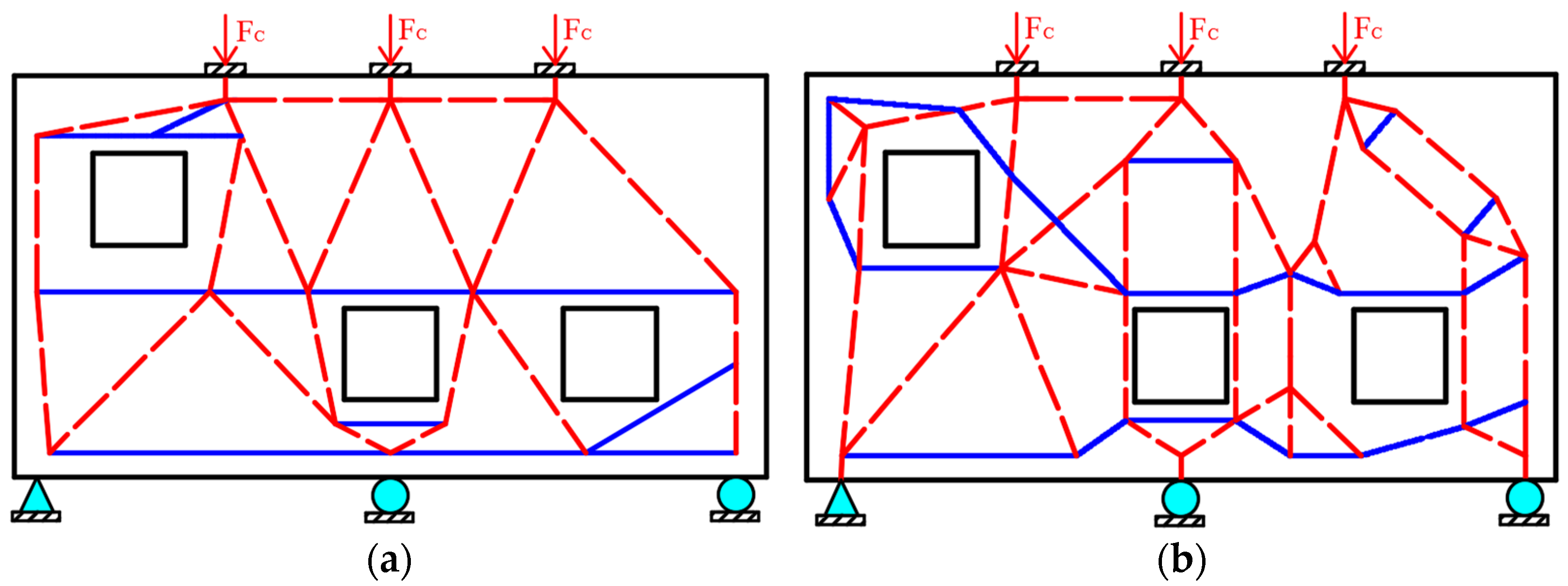
2.4. The STMs in the Existing Literature

For this type of concrete deep beam with openings, many scholars have proposed corresponding STMs by using different methods and use them to guide the reinforcement design. Two STMs were proposed by D. B. Garber et al. [31], and they were named STM C-02 and the STM C-03, as shown in Figure 9, respectively, and the nodes in the models are omitted. When constructing STM C-02, they first studied the load-transfer mechanism based on the FEA results of the concrete deep beam and focused on the constructability of the reinforcement design.
As demonstrated in Figure 8 and Figure 9 through a comparative study of strut-and-tie models (STMs), the proposed STM-04 not only accounts for the stress distribution and load-transfer mechanism in perforated concrete deep beams but also incorporates practical constructability considerations. Although an additional optimization process based on crack propagation simulations was introduced, this approach effectively addresses two critical challenges: ① elimination of model non-uniqueness, as the optimized STM-04 reduces arbitrary variations in topology configuration; ② mitigation of subjective bias, as the crack-driven optimization minimizes reliance on designers’ empirical judgments.

3. Experimental Program

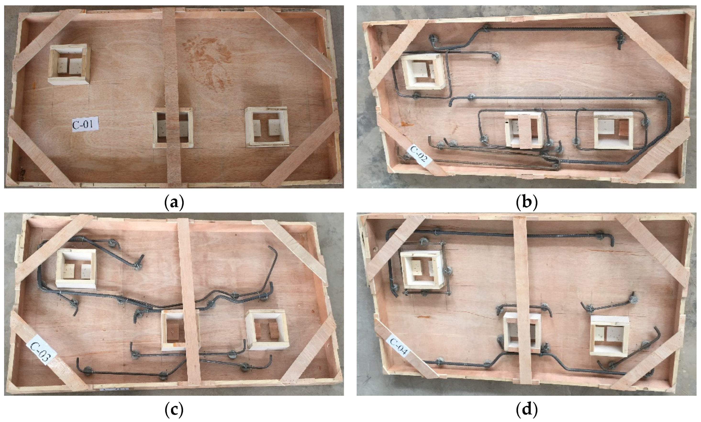
3.1. Specimen Production and Loading Scheme

According to ACI 318-14 [32], using the CAST design software developed by D.A. Kuchma et al. [33], the member internal force and the node area of STM C-02, STM C-03, and STM C-04 were calculated and checked in sequence. The obtained corresponding reinforcement designs are shown in Figure 10. The identification numbering of the reinforcement design variants for the concrete deep beam specimen corresponds to their respective strut-and-tie model (STM) identifiers; that is, reinforcement design C-02 corresponds to STM C-02, and so on.
The formwork configurations and corresponding reinforcement cages of the concrete deep beam specimens are illustrated in Figure 11, with each specimen’s identification number aligned with its reinforcement design designation. To validate the accuracy of the crack propagation simulation result, plain concrete deep beam specimens (designated as specimen C-01) were additionally fabricated. All specimens were cast using C30 fine aggregate concrete. During the casting of the specimens, an insert-type vibrator was used to compact the concrete to ensure its densification. Before the initial setting of the concrete, the surfaces of all specimens were smoothed and covered with plastic film. Once the concrete reached a final setting, a layer of felt was applied to the specimen surfaces, followed by water-spray curing every four hours until the 28-day curing period was completed.
The loading method of the specimens are graded static loading, as shown in Figure 12. The test data were collected by the load sensors, displacement meters, and a static information acquisition instrument. Each loading level of the reinforced concrete specimens was 5 kN, and after loading to the design load, each loading level was 1 kN. After each loading level was completed, the load was maintained for 5 min. During the test of the plain concrete deep beam specimen, each loading level was 1 kN until the specimen failed. A magnifying glass and a handheld crack observer were used to measure the cracking size and crack shape of the specimens, and the relevant test data and test phenomena were recorded.

3.2. Material Performance Test

The steel bar grade is HRB335, and the steel bar diameters are 8 mm, 10 mm, and 12 mm. The mechanical performance indicators of the steel bars obtained in the test are shown in Table 2. The corresponding cubic concrete test block (150 × 150 × 150 mm) was reserved when the specimens were poured. The measured compressive strength of the concrete cube is 31.3 N/mm2, the tensile strength of the concrete is 2.1 N/mm2, and the elastic modulus is 3.10 × 10⁴ N/mm2. The mechanical property test methods for steel reinforcement and concrete were conducted in accordance with Metallic Materials—Tensile Testing—Part 1: Method of Test at Room Temperature (GB/T 228.1-2021) [34] and Standard for Test Methods of Concrete Physical and Mechanical Properties (GB/T 50081-2019) [35], respectively.

4. Test Results and Analysis

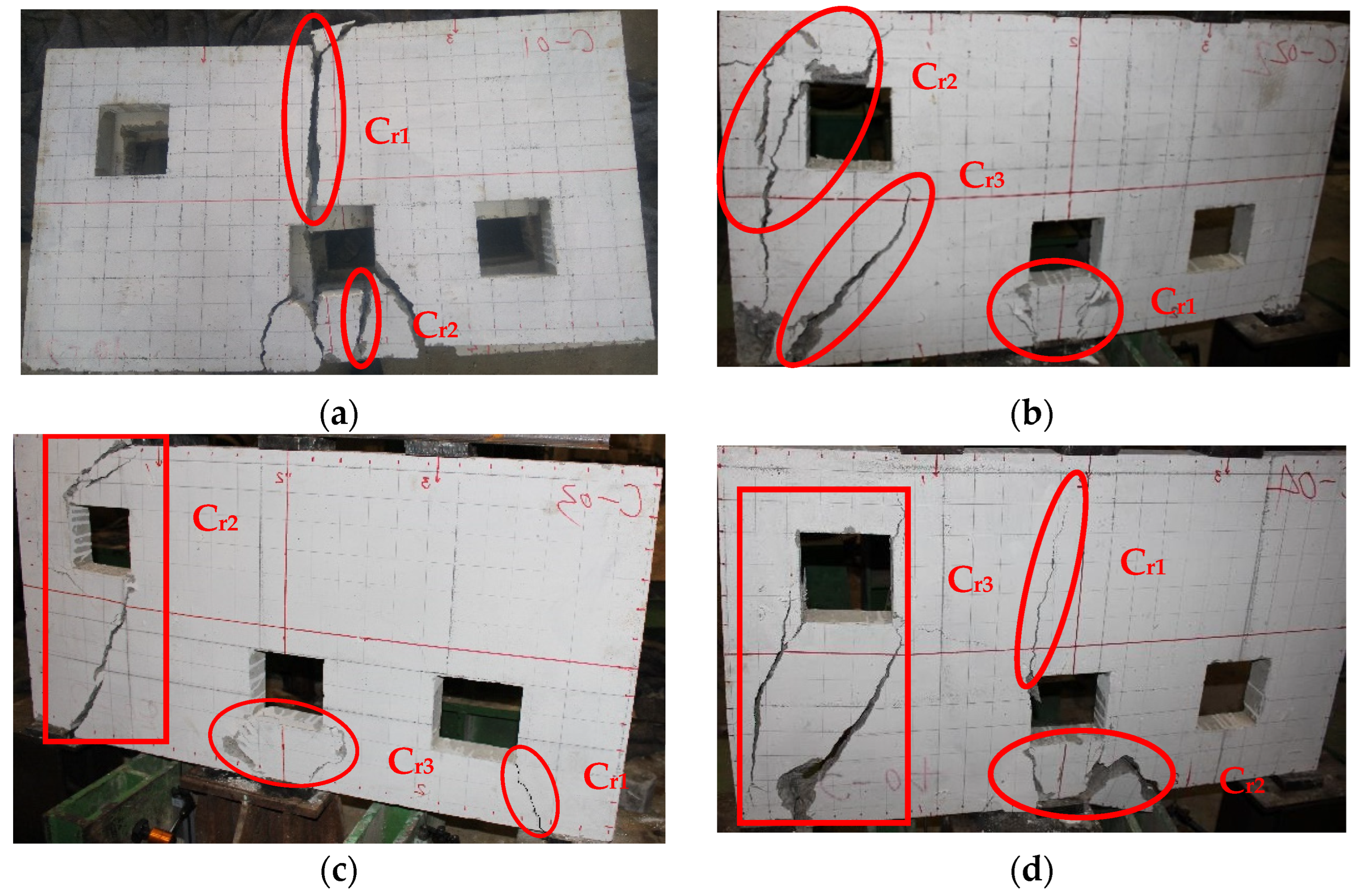
4.1. Failure Morphology

The failure modes of all specimens are illustrated in Figure 13. For specimen C-01, the crack patterns labeled Cr1 and Cr2 in Figure 13a demonstrate close alignment with the crack propagation simulation results (Figure 7), while the remaining cracks observed in specimen C-01 were induced during the specimen disassembly process.
The compressive stress of the middle support was higher than that of the supports at both ends, and the middle opening was close to the middle support, so the concrete between the bottom of the middle opening of specimen C-02 and the middle support cracked first, as shown in crack Cr1 in Figure 13b. However, STM C-02 had several ties (steel bars) under the middle opening, which can effectively limit the development of crack Cr1. With the increase in the load, the crack Cr2 in Figure 13b was produced in specimen C-02 because the left opening was close to the left loading point and the stress at the corner of the opening was concentrated. Following the initiation of crack Cr2, the concrete between the left support and the lower-right corner of the left opening subsequently fractured, generating crack Cr3, as depicted in Figure 13b. The shear failure of specimen C-02 was along crack Cr2 and Cr3.
In the early stage of the loading, the concrete at the lower right corner of the right opening of specimen C-03 cracked first and expanded to the right support, as shown in crack Cr1 in Figure 13c. When the load was high, crack Cr2 was generated between the left loading point and the left support through the left opening. Subsequently, crack Cr3 in Figure 13c was generated, but the STM C-03 was equipped with a tie (steel bar) under the middle opening to effectively limit the continued development of crack Cr3. Specimen C-03 finally failed along crack Cr2.
In STM C-04, the corresponding ties (steel bars) were set in the weak regions. Due to the high compressive stress at the middle support and the close distance to the middle opening, crack Cr1 and crack Cr2 in Figure 13d were generated in specimen C-04, but the two cracks were limited by the corresponding reinforcement and developed slowly. When the load was large, crack Cr3 occurred between the left support and the left opening, which led to the fracture of the specimen.
According to the failure morphologies of specimen C-02, specimen C-03, and specimen C-04, it can be seen that the failure mode of this type of concrete deep beam designed using the STM design method is shear failure.

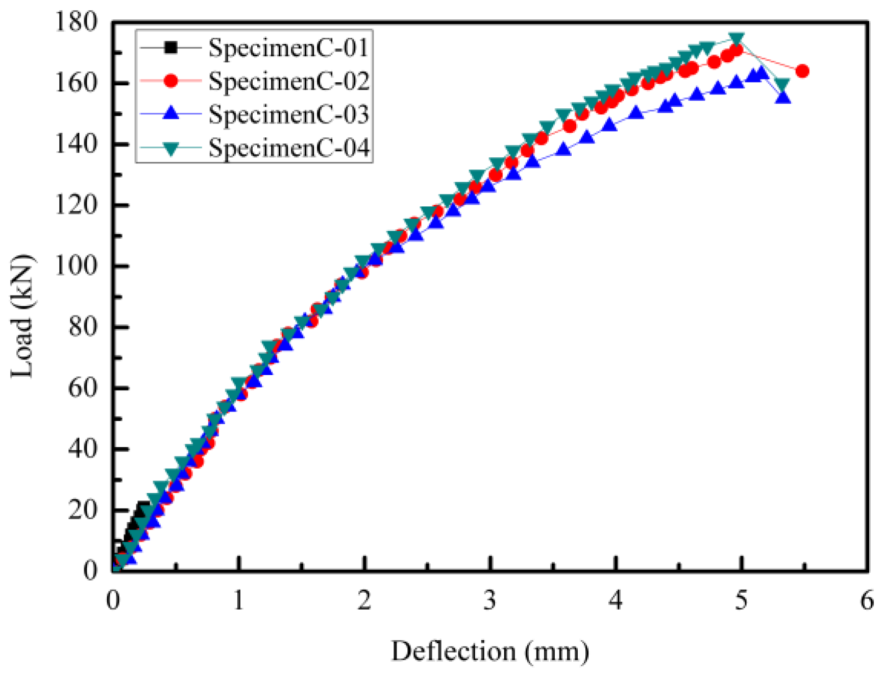
4.2. Performance of the Specimens

Table 3 shows the test results of the concrete deep beam specimens. Pc, Pd, and Pu are the cracking load, design load, and the ultimate bearing capacity, respectively; l0 is the calculated span; Δc is the deflection deformation under the cracking load (Pc); Δu is the deflection at the ultimate bearing capacity (Pu); Δuc reflects the process span from concrete cracking to the depletion of the elastic–plastic deformation capacity of the specimen; and Δu/l0 reflects the ultimate elastic–plastic deformation capacity of the concrete deep beam specimens in the final failure. The load–deflection curves are shown in Figure 13.
As shown in Table 3 and Figure 14, the cracking load and ultimate bearing capacity of specimen C-04 were the largest. The reinforcement design C-04 guided by STM C-04 effectively restrained the initial cracks of the concrete deep beam and delayed the occurrence of the initial crack. The cracking load of specimen C-04 was 4.8% and 6.8% higher than that of specimen C-02 and specimen C-03, respectively. The ultimate bearing capacity of specimen C-04 was 2.3% and 7.4% higher than that of specimen C-02 and specimen C-03, respectively. Correspondingly, the Pu/Pd of specimen C-04 was also the largest (1.17). Except for specimen C-01, the ultimate bearing capacity of the other reinforced concrete deep beam specimens exceeded the design load. This also verified the validity and conservation of the STM design method.
The Δc of specimen C-04 was the largest, and the Δu of specimen C-04 was smaller than that of specimen C-03, the same as that of specimen C-02. Specimen C-04 exhibited the best deformation ability before concrete cracking, and its deformation ability was weakened after concrete cracking. After concrete cracking, the ductility of specimen C-04 was inferior to that of specimen C-02, while being essentially comparable to that of specimen C-03.
The maximum crack widths of specimen C-02, specimen C-03, and specimen C-04 under the design load were 1.20 mm, 1.50 mm, and 1.0 mm, respectively. This is because STM C-04 was more in line with the load-transfer mechanism of the concrete deep beam, and the reinforcement design of C-04 was more accurate in the position of the steel bars. Therefore, the Δuc of specimen C-04 was the smallest, and the process span between the cracking of the concrete and the depletion of the elastic–plastic deformation capacity of specimen C-04 was smaller. The Δu/l0 of specimen C-04 was smaller than that of specimen C-03, which was the same as that of specimen C-02. The ultimate elastic–plastic deformation capacity of the reinforced concrete deep beam specimens was basically the same.
The stiffness values of each specimen at different stages are presented in Table 4. In the table, K0 represents the initial elastic stiffness of the specimens, Kc denotes the secant stiffness corresponding to the cracking load, and Ku indicates the secant stiffness at the ultimate bearing capacity. The relative initial stiffness is normalized as k0 = 1.00.
As evident from Table 4, the stiffness degradation of all specimens before concrete cracking exhibited minor variations, with specimen C-04 showing faster early-stage stiffness degradation. Post-cracking, however, specimen C-04 demonstrated relatively slower stiffness reduction, resulting in higher residual stiffness at ultimate failure. This behavior can be attributed to the precise reinforcement positioning achieved by the proposed design method, which more effectively constrained the crack propagation in the concrete and mitigated stiffness degradation—a notable advantage of this methodology. Overall, the three reinforced concrete deep beam specimens exhibited comparable rates of stiffness degradation.

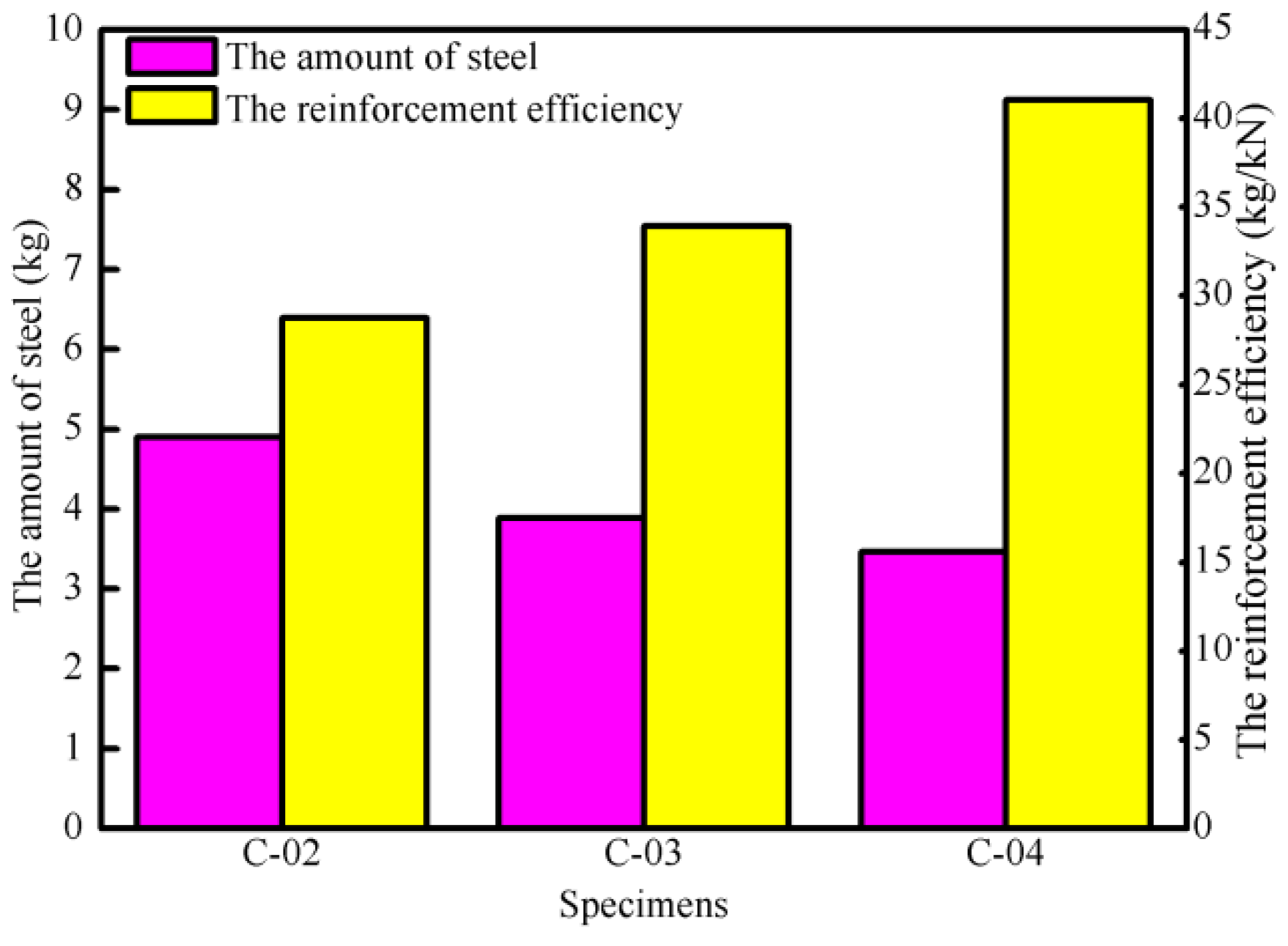
4.3. Steel Consumption and Reinforcement Efficiency

The steel consumption and reinforcement efficiency of the concrete deep beam specimens are shown in Figure 14. The formula for calculating the reinforcement efficiency (ρs) can be expressed as follows:
ρ s = P u P 0 W s
where P0 is the ultimate bearing capacity of the plain concrete specimen (kN) and Ws is the amount of steel used for the specimen (kg).
It can be seen from Figure 15 that the steel consumption of specimen C-04 is 29.4% and 11.1% less than that of specimen C-02 and specimen C-03, respectively. The reinforcement efficiency of specimen C-04 was the highest, which was 42.6% and 21.0% higher than that of specimen C-02 and specimen C-03, respectively. The concrete deep beam designed by STM C-04 proposed in this paper has better economic rationality and more fully utilized steel bars.

5. Conclusions

The relevant conclusions can be obtained as follows:
(1)
The design method based on the optimized STM is suitable for the reinforcement design of the concrete deep beam with openings and has good reliability in terms of determining the bearing capacity. This concrete deep beam designed by STM C-04 has certain advantages in delaying concrete cracking, improving its bearing capacity and reducing steel consumption.
(2)
Compared to the STMs in the existing literature, the concrete deep beam designed with STM C-04 can increase the cracking load by up to 6.8% and the bearing capacity by up to 7.4%, and the corresponding steel consumption can be saved up to 29.4%.
(3)
The perforated concrete deep beam designed using the strut-and-tie model (STM-04) developed in this study exhibited superior deformation capacity but faster stiffness degradation prior to concrete cracking. After cracking, its deformation performance and stiffness degradation behavior were essentially identical to those of the perforated deep beams designed with STM-02 and STM-03.
(4)
The concrete deep beam designed using the design method of STM C-04 has the highest reinforcement efficiency, which can be up to 42.6% higher than the concrete deep beams designed by the other two STMs. That is to say, the economic rationality of the reinforcement design guided by the STM C-04 is better.
(5)
The concrete deep beam with openings using this STM design method is subject to shear failure, which should be considered during subsequent reinforcement design.
(6)
This study has limitations regarding specimen size effects, boundary conditions, the shape of the openings, and parametric finite element analysis. Future research will focus on addressing these aspects.

Author Contributions

Conceptualization, H.C. and M.D.; methodology, H.C.; software, Y.S. and M.D.; validation, H.C., Y.S. and M.D.; formal analysis, Y.S.; investigation, H.C.; resources, H.C.; data curation, M.D.; writing—original draft preparation, Y.S.; writing—review and editing, H.C.; visualization, H.C.; supervision, M.D.; project administration, H.C.; funding acquisition, H.C. All authors have read and agreed to the published version of the manuscript.

Funding

This study is funded by the “Open Project of the Key Laboratory of Concrete and Pre-stressed Concrete Structures of Ministry of Education of Southeast University” (Grant No. CPCSME 2022-10); the “Opening project of the Shandong Key Laboratory of Civil Engineering Disaster Prevention and Mitigation (Shandong University of Science and Technology)” (Grant No. CDPM2021KF09).

Data Availability Statement

The original contributions presented in the study are included in the article, further inquiries can be directed to the corresponding author.

Conflicts of Interest

The authors declare no conflict of interest.

References

  1. Rabi, M.; Shamass, R.; Cashell, K. Structural performance of stainless steel reinforced concrete members: A review. Constr. Build. Mater. 2022, 325, 126673. [Google Scholar] [CrossRef]
  2. Aksoylu, C.; Ozkilic, Y.O.; Hakeem, I.Y.; Kalkan, I. Effects of the location and size of web openings on shear behavior of clamped-clamped reinforced concrete beams. Comput. Concr. 2024, 33, 251–264. [Google Scholar] [CrossRef]
  3. Ring, J.D.; Tanner, J.E. Evaluation of Masonry Beams with Openings and Validation Using a Strut-and-Tie Model. J. Struct. Eng. 2021, 147, 04021195. [Google Scholar] [CrossRef]
  4. Özkılıç, Y.O.; Aksoylu, C.; Hakeem, I.Y.; Özdöner, N.; Kalkan, I.; Karalar, M.; Stel’makh, S.A.; Shcherban, E.M.; Beskopylny, A.N. Shear and Bending Performances of Reinforced Concrete Beams with Different Sizes of Circular Openings. Buildings 2023, 13, 1989. [Google Scholar] [CrossRef]
  5. Zaborac, J.; Choi, J.; Bayrak, O. Assessment of Deep Beams with Inadequate Web Reinforcement Using Strut-and-Tie Models. Eng. Struct. 2020, 218, 110832. [Google Scholar] [CrossRef]
  6. Aksoylu, C.; Özkılıç, Y.O.; Çeledir, E.; Başaran, B.; Arslan, M.H. Experimental and numerical investigation of bending performance of prestressed purlins having different longitudinal web opening. Structures 2024, 60, 105839. [Google Scholar] [CrossRef]
  7. Aksoylu, C.; Özkılıç, Y.O.; Çeledir, E.; Arslan, M.H. Bending performance of dapped-end beams having web opening: Experimental and numerical investigation. Structures 2023, 48, 736–753. [Google Scholar] [CrossRef]
  8. Meng, C.; Li, K.; Zhou, Z.; Zhang, H. Simulation study on reinforced concrete deep beams with openings designed using topology optimization—STM method. J. Shaoyang Univ. (Nat. Sci. Ed.) 2024, 21, 38–47. [Google Scholar]
  9. GB 50010-2010; Ministry of Housing and Urban-Rural Development of the People’s Republic of China. Code for Design of Concrete Structures. China Architecture & Building Press: Beijing, China, 2011.
  10. Mozaffari, S.; Akbarzadeh, M.; Vogel, T. Graphic statics in a continuum: Strut-and-tie models for reinforced concrete. Comput. Struct. 2020, 240, 106335. [Google Scholar] [CrossRef]
  11. Chetchotisak, P.; Teerawong, J.; Yindeesuk, S. Modified interactive strut-and-tie modeling of reinforced concrete deep beams and corbels. Structures 2022, 45, 284–298. [Google Scholar] [CrossRef]
  12. Abbood, I.S. Strut-and-tie model and its applications in reinforced concrete deep beams: A comprehensive review. Case Stud. Constr. Mater. 2023, 19, e02643. [Google Scholar] [CrossRef]
  13. Jing, Z.-N.; Liu, R.-G.; Xie, G.-H.; Liu, D. Shear Strengthening of Deep T-Section RC Beams with CFRP Bars. Materials 2021, 14, 6103. [Google Scholar] [CrossRef] [PubMed]
  14. Xia, Y.; Langelaar, M.; Hendriks, M.A. Automated optimization-based generation and quantitative evaluation of Strut-and-Tie models. Comput. Struct. 2020, 238, 106297. [Google Scholar] [CrossRef]
  15. Yang, X.Y.; Xie, Y.M.; Steven, G.P.; Querin, O.M. Bidirectional Evolutionary Method for Stiffness Optimization. AIAA J. 1999, 37, 1483–1488. [Google Scholar] [CrossRef]
  16. Xia, Y.; Langelaar, M.; Hendriks, M.A. A critical evaluation of topology optimization results for strut-and-tie modeling of reinforced concrete. Comput. Civ. Infrastruct. Eng. 2020, 35, 850–869. [Google Scholar] [CrossRef]
  17. El-Zoughiby, M.E.; Amasha, R.E.; Ghaleb, A.A. A unifying strut-and-tie model for conventionally reinforced link beams. Eng. Struct. 2023, 299, 117109. [Google Scholar] [CrossRef]
  18. Nie, Y.; Zhang, J.; Liu, D.; Lan, T.; Xiao, D.; Xiong, M.; Dong, Z. Strut-and-tie model and reinforcement design method for gusset in the containment vessel. Structures 2024, 65, 106693. [Google Scholar] [CrossRef]
  19. Abarkan, I.; Rabi, M.; Ferreira, F.P.V.; Shamass, R.; Limbachiya, V.; Jweihan, Y.S.; Santos, L.F.P. Machine learning for optimal design of circular hollow section stainless steel stub columns: A comparative analysis with Eurocode 3 predictions. Eng. Appl. Artif. Intell. 2024, 132, 107952. [Google Scholar] [CrossRef]
  20. Rabi, M.; Shamass, R.; Cashell, K. Description of the constitutive behaviour of stainless steel reinforcement. Case Stud. Constr. Mater. 2024, 20, e03013. [Google Scholar] [CrossRef]
  21. Chen, H.; Wang, L.; Zhong, J. Study on an Optimal Strut-And-Tie Model for Concrete Deep Beams. Appl. Sci. 2019, 9, 3637. [Google Scholar] [CrossRef]
  22. Resmy, V.R.; Rajasekaran, C. Evolutionary Topology Optimization of Structural Concrete Under Various Load Cases. In Advances in Civil Engineering; Singh, R.M., Sudheer, K.P., Kurian, B., Eds.; Lecture Notes in Civil Engineering; Springer: Singapore, 2021; Volume 83, pp. 369–380. ISBN 978-981-15-5643-2. [Google Scholar]
  23. Rabi, M.; Cashell, K.; Shamass, R. Ultimate behaviour and serviceability analysis of stainless steel reinforced concrete beams. Eng. Struct. 2021, 248, 113259. [Google Scholar] [CrossRef]
  24. Rabi, M.; Cashell, K.; Shamass, R. Flexural analysis and design of stainless steel reinforced concrete beams. Eng. Struct. 2019, 198, 109432. [Google Scholar] [CrossRef]
  25. Kumar, R.; Nayak, G.C. Numerical Modeling of Tensile Crack Propagation in Concrete Dams. J. Struct. Eng. 1994, 120, 1053–1074. [Google Scholar] [CrossRef]
  26. Walraven, J.C.; Reinhardt, H.W. Theory and experiments on the mechanical behavior of cracks in plain and reinforced concrete subjected to shear loading. Heron 1981, 26, 68. [Google Scholar]
  27. Jayasuriya, A.; Bandelt, M.J.; Adams, M.P. Stochastic Mesoscopic Modeling of Concrete Systems Containing Recycled Concrete Aggregates Using Monte Carlo Methods. ACI Mater. J. 2022, 119, 3–18. [Google Scholar] [CrossRef]
  28. van Mier, J.G.; van Vliet, M.R.; Wang, T.K. Fracture mechanisms in particle composites: Statistical aspects in lattice type analysis. Mech. Mater. 2002, 34, 705–724. [Google Scholar] [CrossRef]
  29. Al-Kheetan, M.J.; Jweihan, Y.S.; Rabi, M.; Ghaffar, S.H. Durability Enhancement of Concrete with Recycled Concrete Aggregate: The Role of Nano-ZnO. Buildings 2024, 14, 353. [Google Scholar] [CrossRef]
  30. Shamass, R.; Limbachiya, V.; Ajibade, O.; Rabi, M.; Lopez, H.U.L.; Zhou, X. Carbonated Aggregates and Basalt Fiber-Reinforced Polymers: Advancing Sustainable Concrete for Structural Use. Buildings 2025, 15, 775. [Google Scholar] [CrossRef]
  31. Garber, D.B.; Gallardo, J.M.; Huaco, G.D.; Samaras, V.A.; Breen, J.E. Experimental Evaluation of Strut-and-Tie Model of Indeterminate Deep Beam. ACI Struct. J. 2014, 111, 51686738. [Google Scholar] [CrossRef]
  32. Wight, J.K.; American Concrete Institute (Eds.) Building Code Requirements for Structural Concrete (ACI 318-08) and Commentary (ACI 318R-08): An ACI Standard; ACI: Farmington Hills, MI, USA, 2008; ISBN 978-0-87031-264-9. [Google Scholar]
  33. Kuchma, D.A.; Tjhin, T.N. CAST (Computer Aided Strut-and-Tie) Design Tool. In Proceedings of the Structures 2001, Washington, DC, USA, 21–23 May 2001; American Society of Civil Engineers: Washington, DC, USA, 2001; pp. 1–7. [Google Scholar]
  34. GB/T 228.1-2010; Metallic Materials—Tensile Testing—Part 1: Method of Test at Room Temperature. China Architecture & Building Press: Beijing, China, 2010.
  35. GB/T 50081-2019; Standard for Test Methods of Concrete Physical and Mechanical Properties. China Architecture & Building Press: Beijing, China, 2019.
Figure 1. Design drawing of the concrete deep beam specimen (unit: mm).
Buildings 15 01382 g001
Figure 2. Topology optimization results of the specimen.
Buildings 15 01382 g002
Figure 3. Stress contour plot of the specimen’s topology configuration: (a) principal tensile stress; (b) principal compressive stress.
Buildings 15 01382 g003
Figure 4. The initial STM of the specimen.
Buildings 15 01382 g004
Figure 5. Numerical model for crack propagation simulation.
Buildings 15 01382 g005
Figure 6. Constitutive relationship of aggregate.
Buildings 15 01382 g006
Figure 7. Numerical simulation results of crack propagation in concrete deep beam specimens.
Buildings 15 01382 g007
Figure 8. The STM of the specimen constructed in this paper.
Buildings 15 01382 g008
Figure 9. The STMs constructed by D. B. Garber et al. [31] for the concrete deep beam: (a) STM C-02; (b) STM C-03.
Buildings 15 01382 g009
Figure 10. Different reinforcement designs of the concrete deep beam specimen: (a) C-02; (b) C-03; (c) C-04.
Buildings 15 01382 g010
Figure 11. The formworks and reinforcement cages of all specimens: (a) specimen C-01; (b) specimen C-02; (c) specimen C-03; (d) specimen C-04.
Buildings 15 01382 g011
Figure 12. The loading diagram of the specimens.
Buildings 15 01382 g012
Figure 13. Failure morphologies of the concrete deep beam specimens: (a) specimen C-01; (b) specimen C-02; (c) specimen C-03; (d) specimen C-04.
Buildings 15 01382 g013
Figure 14. Load–deflection curves of the specimens.
Buildings 15 01382 g014
Figure 15. Steel consumption and the reinforcement efficiency of specimens.
Buildings 15 01382 g015
Table 1. Parameter settings for BESO.
Filter RadiusVolume FractionEvolutionary Rate (ER)Convergence Tolerance
3 mm0.31%0.1%
Table 2. Mechanical property indicators of steel bars.
Diameter (mm)Yield Strength/fy,m (MPa)Ultimate Strength/fu,m (MPa)Yield Strain/εy,m (10−6)
84826032101
104385511965
124075121915
Table 3. Test value of the bearing capacity and deflection of different specimens.
SpecimenPc (kN)Pd (kN)Pu (kN)Δc (mm)Δu (mm)ΔucΔu/l0Pu/Pd
C-01-15021----0.14
C-021051501712.144.962.320.00431.14
C-031031501632.125.162.430.00451.09
C-041101501752.244.962.210.00431.17
Table 4. The stiffness table of specimens.
Specimenk0Kc/K0Ku/K0
C-021.000.670.36
C-031.000.600.32
C-041.000.620.39
Disclaimer/Publisher’s Note: The statements, opinions and data contained in all publications are solely those of the individual author(s) and contributor(s) and not of MDPI and/or the editor(s). MDPI and/or the editor(s) disclaim responsibility for any injury to people or property resulting from any ideas, methods, instructions or products referred to in the content.

