Abstract
As the core technology for mechanized installation of tunnel folding steel arch frames, snap-fit connection optimization proves critical in enhancing the load-bearing efficiency of support systems and addressing surrounding rock deformation and instability caused by excavation-induced stress redistribution. Addressing the theoretical gaps in existing research regarding snap-fit selection mechanisms and quantitative evaluation criteria, this study adopts a combined approach of numerical simulation and field monitoring verification based on the excavation compensation concept to systematically investigate the load-bearing characteristics of folding steel arch frames with different snap-fit configurations. Key findings include (1) identification of 20 mm as the optimal joint diameter, where the vertical displacements of Type A and B snap-fit connections reached their minimum values of 43.1 mm and 39.2 mm, respectively; (2) demonstration of significant geometric configuration effects on principal stress distribution, with Type B connections exhibiting 4.5% lower maximum principal stress compared to Type A, effectively mitigating stress concentration; and (3) field monitoring data verification, revealing that Type B connections achieved 15.8% lower stress values than Type A at critical crown sections, satisfying yield strength requirements while demonstrating enhanced resistance to surrounding rock deformation induced by excavation-induced geostress redistribution. These results confirm Type B snap-fit connections as superior structural solutions for folding steel arch frames, thereby facilitating the advancement of mechanized installation technology for tunnel steel arch frames.
1. Introduction
Since the beginning of the 21st century, China has become the fastest-growing country in tunnel and underground engineering development due to continuous economic growth and major infrastructure programs [1,2,3]. By the end of 2022, China had 17,873 operational railway tunnels with a total length of 21,978 km, and 22,850 highway tunnels spanning 26,784 km [4]. The large-scale construction of transportation tunnels has driven advancements in construction technologies and mechanization, with innovative equipment such as three-boom hydraulic drills, arch frame assembly machines, and intelligent lining trolleys being successfully applied in projects like the Zhengzhou–Wanzhou Railway and the Beijing–Zhangjiakou Railway [5,6,7]. Although mechanized construction has significantly improved, tunnel excavation disrupts the original stress equilibrium of surrounding rock masses, leading to stress redistribution and tensile stress concentration that frequently cause rock failure. The excavation compensation theory [8] emphasizes that implementing stress compensation support during the critical window period before tensile stress concentration can restore the pre-excavation three-dimensional stress state, thereby controlling rock deformation. The excavation compensation method [9] proposes that prestressed active support effectively limits deformation by rapidly compensating for stress loss. Academic He Manchao developed a large deformation control system using NPR materials, achieving remarkable success in tunnel stability [10]. Additionally, high-stiffness arch frame systems combined with rapid support technologies establish a “resist-then-yield” compensation mechanism to mitigate excavation-induced stress redistribution and associated hazards. Therefore, investigating the bearing performance of folding steel arch frames under excavation unloading conditions and their rapid installation methods is critical for enhancing the effectiveness of excavation compensation techniques, reducing the adverse effects of geostress, and advancing both the load-bearing capacity of primary support systems and the mechanization level of tunnel construction.
Regarding the erection equipment for tunnel steel arch frames, numerous scholars both domestically and internationally have conducted extensive research. Guo et al. [11] developed a novel mechanized supporting construction equipment integrating multiple functions for steel arch frame erection in tunnels. Jianglu Mechanical and Electrical Group Co., Ltd. Industrial Development Company designed the SGDC700 tunnel arch multi-function installing truck, which is capable of grasping and connecting arch frames in mid-air using flanges [12]. Wang et al. [13] independently developed an intelligent arch erection device, which is compatible with the supporting structure and employs an assembly approach to construction. Liu et al. [14] innovated the SCDZ133 tunnel arch multi-function installing truck, addressing issues such as high labor intensity and low efficiency in the erection of tunnel steel arch frames. Sun et al. [15] developed an intelligent arch frame erection machine along with assembly devices such as automatic assembly nodes and longitudinal positioning connections. He et al. [16] designed a grasping and docking mechanism for tunnel boring machine (TBM) steel arch splicing manipulators. Zhao et al. [17] analyzed the usage of the XZGMT411 multi-functional arch erection machine in the construction of the Yuelongmen Tunnel. Hudita Construction designed a remote and unmanned construction system for assembling steel arch frames [18]. Krauze et al. [19] developed a system for transporting and installing tunnel steel arch frames. To minimize manual operations in arch erection, Ni [20] developed a teleoperated assembly system for unmanned steel arch construction. The aforementioned literature primarily focuses on the research progress of steel arch frame erection equipment in the initial support phase of tunnels.
In terms of innovative steel arch frames, Sun et al. [21] introduced a snap-fit machining connection pre-stressed concrete solid square pile, providing a reliable basis for the improvement and application of steel arch frame connection methods. Wang [22] designed a retractable movable arch frame, analyzing its supportive effectiveness in tunnels with large deformations in layered soft rock beds. Li et al. [23] investigated the effects of multi-arch spatial combination and shotcrete on primary support, analyzing the influence of arch spacing and longitudinal connection spacing on the mechanical properties of the support system. Xu et al. [24] designed a novel grid steel frame core–tube bracing system and compared the strain characteristics of two arched supports under compression. Ma et al. [25] found that failures in tunnel steel arch supports are primarily induced by axial stress, and that incorporating longitudinal connections can significantly enhance their load-bearing capacity. Through experimental investigations on I-beam and hollow-pipe string joints under both static and cyclic loading conditions, Song et al. [26] systematically evaluated the structural behavior of connections, with particular emphasis on their failure mechanisms across different loading regimes. Yue et al. [27] conducted a comprehensive investigation into the critical challenges of segmented connections in steel arch frames for primary tunnel support systems, proposing targeted structural optimization strategies to improve their mechanical performance. Li et al. [28] developed an innovative longitudinal connection system utilizing steel plates. Through field-scale experimental studies, they quantitatively compared the structural efficacy of this plate-based solution against traditional reinforcing bar connections within steel arch support systems. He et al. [29] addressed the problem of large deformations in squeeze-type soft rock tunnels, researching an adaptive steel arch frame joint suitable for such tunnels. Zhang et al. [30,31] proposed design schemes for snap-fit, adhesive, and interference-fit assembly steel arch frame joints suitable for machining construction. Their research found that snap-fit steel arch frames exhibit the best load-bearing performance.
In conclusion, while significant progress has been made in tunnel steel arch frame installation equipment, traditional arch segments still require manual bolt connections even with mechanical assistance, resulting in high labor intensity, complex installation procedures, and low efficiency [32]. These limitations impede the timely stress compensation required by the excavation compensation method to control surrounding rock instability caused by geostress redistribution, thereby restricting deformation mitigation. Consequently, developing novel folding steel arch frames compatible with installation machinery is critical for achieving mechanized deployment and timely support. Although current research confirms that snap-fit folding steel arch frames offer promising solutions [33], systematic investigations remain lacking regarding the influence of snap-fit types on load-bearing characteristics, mechanisms governing stress states at joint sections, and the contact behavior of connecting plates. Additionally, selection criteria for snap-fit configurations to balance rapid mechanized erection with effective support remain unclear. To address these gaps, this study evaluates existing folding arch frame designs and systematically investigates the mechanical performance of snap-fit-type folding frames through displacement–stress characteristics, joint stress distribution, and plate contact dynamics. Field test comparisons further identify optimal snap-fit configurations, achieving mechanized rapid erection, prompt support, and effective deformation control. These findings provide critical insights for advancing mechanized installation technology in tunnel engineering.
2. Snap-Fit Folding Steel Arch Frames for Tunnels
2.1. Folding Steel Arch Frames for Machining Arch Frame Erection in Tunnels
The folding steel arch frame is a novel form suitable for machining assembly, comprising a minimum of two arch frame units. The adjacent arch frame units are joined using a piecing device. The piecing device facilitates the fixed connection between adjacent arch units, eliminating the need for manual bolt fixation at the connecting ends of the arch units. This enhances erection efficiency and quality, reducing labor intensity for operational personnel.
The folding steel arch frame, as depicted in Figure 1, encompasses various-sized segments and piecing devices. In accordance with tunnel cross-sectional dimensions and construction methods, the processed steel arch frame segments are initially assembled outside the tunnel opening. Using an arch erection machine, the entire steel arch frame is lifted in a single operation. One of the gripping arms is employed to secure the middle segment of the arch at the crown. Subsequently, the other two arms are used to unfold the steel arch frame segments on either side, and the connection devices facilitate their linkage. Once the steel arch frame is erected, at the tunnel construction site, a multi-functional operation trolley enables the machining erection of the tunnel steel arch frame. Prompt shotcrete operations follow to swiftly establish a collaborative structural load-bearing system between the steel arch frame and the sprayed concrete.
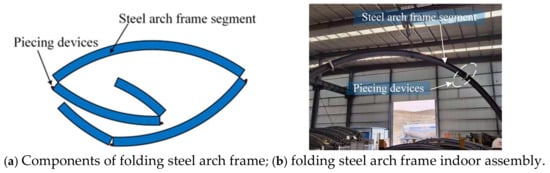
Figure 1.
Folding steel arch frame.
2.2. Connection Methods for Folding Steel Arch Frames
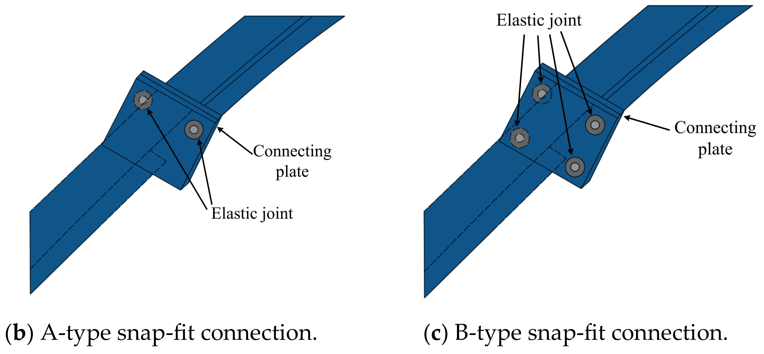
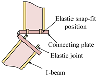
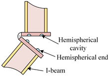
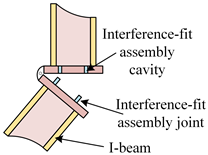
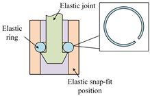
Currently, there are three methods of piecing devices between segments of the folding steel arch frame, as illustrated in Table 1: snap-fit connections, adhesive connections, and interference-fit assembly connections. Snap-fit connections primarily rely on the tight clamping force between elastic joints and elastic snap-fit positions to secure the connection between arch segments. Elastic joints and elastic snap-fit positions are located on two connecting plates. When the elastic joint passes through the elastic snap-fit position, it causes the elastic ring to expand. After the elastic joint passes through the elastic ring, the elastic ring exerts clamping force on the joint through elastic reset.

Table 1.
Connection types and characteristics of folding steel arch frames.
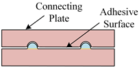
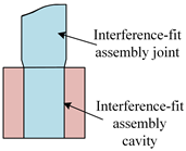
Adhesive connections consist of a semi-spherical end on one connecting plate and a cavity on another connecting plate, with the semi-spherical end and the cavity arranged in a floral pattern. This connection relies on pre-set adhesive within the cavity, which, when compressed, forms a stable adhesive surface between the connecting plates to achieve the purpose of connection. Interference-fit assembly connections mainly comprise interference-fit assembly joints and assembly cavities. This connection exploits the elastic deformation capability of materials. During the application of force, the hole diameter increases, and upon recovery, it generates a clamping force on the axis, facilitating the connection between joint components.
The snap-fit connection exhibits excellent assembly performance, making it easy for on-site processing and assembly and boasting favorable machining properties. While adhesive connections can uniformly transmit stress and withstand loads within the adhesive range, preventing stress concentration and potential damage to joint structures, they typically require waterproof treatment at the adhesive site. Moreover, adhesive connections possess a certain time-dependent strength, demanding high resistance to oxidation and considerable service life of the adhesive. Interference-fit assembly connections simplify joint structures, facilitating straightforward and convenient processing. However, this connection is suitable for erection under impact loads and demands high precision in the structural dimensions at the joint. Through a comparative analysis considering assembly, durability, and processability, and aligning with the on-site conditions necessary for tunnel steel arch frame erection, it can be concluded that snap-fit connections offer high practicality. They can substitute manual connections between steel arch frames, ensuring a tight connection among arch frame segments, enhancing overall structural stability, and minimizing safety risks during machining construction. This promotes the smooth progress of machining tunnel arch frame erection.
2.3. Types of Snap-Fit Connection
The local structure of the snap-fit connection, as illustrated in Figure 2a, is designed to facilitate the smooth passage of the elastic joint through the snap-fit position. To achieve it, the internal diameter of the cavity in the elastic snap-fit position is 1.05 to 1.1 times the diameter of the joint. The internal diameter of the elastic ring is 0.8 to 0.95 times the diameter of the joint. This configuration ensures that, as the elastic joint passes through the elastic ring, a self-locking force is provided. The elastic snap-fit position is equipped with an annular groove for installing the elastic ring, with the groove’s specifications being 1.1 to 1.5 times the size of the elastic ring. This facilitates the erection of the elastic ring and provides expansion space for the elastic ring when the elastic joint passes through it. The elastic ring features notches, ensuring the passage of the elastic joint through the elastic ring while maintaining a self-locking fixation of the elastic joint by the elastic ring.
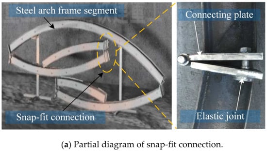

Figure 2.
Types of snap-fit connection.
The elastic ring is manufactured from high-quality spring steel, providing excellent elasticity and strength. The efficacy of folding steel arch frames in providing structural support is predominantly contingent on the design of snap-fit connections. Past research has indicated that when the thickness of the end plate exceeds 16 mm, it ceases to exert effective control over the nodal bearing capacity [34]. Consequently, this paper establishes the thickness of the snap-fit joint connecting plate at 16 mm, ensuring that the load-bearing capacity of the snap-fit joint is primarily determined by the number of enclosed elastic joints and the dimensions of the elastic joint. Two types of snap-fit connections are introduced, incorporating two elastic joints and four elastic joints, designated A-type and B-type, respectively (refer to Figure 2b,c).
3. Analysis of Mechanical Performance of Folding Steel Arch Frames with Different Snap-Fit Types
3.1. Numerical Calculation Model Building
The folding steel arch frame consists of I-beams, connection plates, and flexible joints. ABAQUS 6.14.4 enables independent material parameter definition for individual components with corresponding mesh generation, demonstrating robust stability in handling highly nonlinear problems. Static analysis of the folding steel arch frame was performed using ABAQUS [35]. A three-dimensional model was developed on a Windows 10 system (Intel® Core™ i7-12700F CPU @2.10 GHz, 16GB RAM) utilizing hexahedral elements (HEX), achieving high computational accuracy with relatively low resource consumption. The model mesh was partitioned using C3D8R elements (8-node linear brick reduced integration elements) for more accurate displacement results.
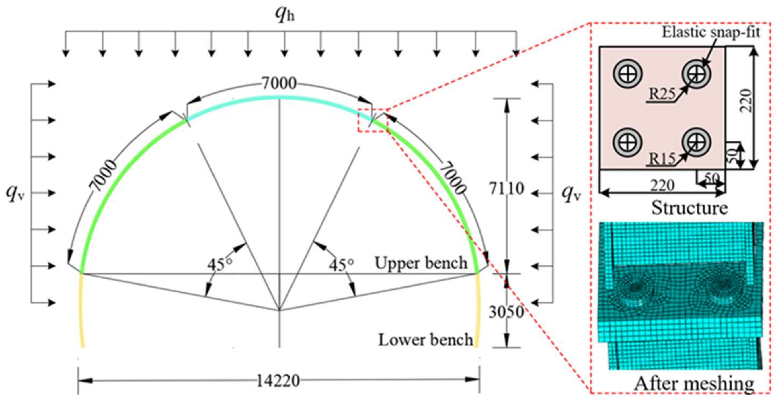
In the model development process, interactions among various components of the steel arch frame joints are considered. The interaction function module is utilized for definition, and the model is appropriately simplified to obtain reliable and accurate computational results. For the numerical simulation of the snap-fit joints, the following assumptions are made: (1) the self-locking effect of the elastic ring on the elastic joint is realized through the Tie constraint; (2) mutual contact between the connecting plates of the snap-fit joint is considered, neglecting tangential friction and only accounting for normal contact through “hard” contact, allowing for separation after contact; and (3) the hinged structure between the connecting plates of the snap-fit connection primarily facilitated the rotation between steel arch frame segments, simulated through the HINGE combination property. In practical engineering, the presence of longitudinal reinforcement limits the out-of-plane buckling deformation of the steel arch frame to some extent. Therefore, this paper only considers the in-plane deformation of the folding steel arch frame. Constraints are applied in the Z-direction in the model, and due to the action of the lock foot anchor rod, the foot position of the folding steel arch frame is set as completely fixed. The model is illustrated in Figure 3. The typical grid size of a steel frame is 50 × 50 × 22 mm. The typical grid size at the joint is about 3 × 3 × 3 mm, and the grid is encrypted at the connections.
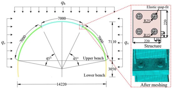
Figure 3.
Numerical model of folding steel arch frame (unit: mm).
3.2. Numerical Model Parameters
The A- and B-type snap-fit connections are both positioned at a 45° angle to the arch crown. The folding steel arch frame is constructed using No. 16 I-beams, and the material parameters for the folding steel arch frame are presented in Table 2. The initial support steel arch frame of the tunnel is subjected to surrounding rock pressure, with its load decomposed into horizontal pressure qv and vertical pressure qh acting on the steel arch frame. Therefore, the effect of the surrounding rock on the folding steel arch frame can be equivalently simulated by applying horizontal and vertical pressures. According to the Code for the Design of Railway Tunnels (2016) [36] regarding the calculation method for deep-buried tunnel loads, the vertical pressure qh is set to 259.2 kPa, and the horizontal pressure qv is set to 103.7 kPa.
Table 2.
Material parameters of the folding steel arch frame.
In summary, the calculation scenarios for folding steel arch frames with different specifications under surrounding rock pressure are outlined in Table 3. To investigate the impact of the elastic joint diameter on the folding steel arch frame, in this study, we design elastic joints with diameters of d = 16 mm, d = 20 mm, and d = 24 mm, analyzing the influence of different diameter snap-fit types on the load-bearing performance of the folding steel arch frame.
Table 3.
Different calculation conditions of folding steel frames.
3.3. Simulation Results Analysis
3.3.1. Displacement Characteristics of the Folding Steel Arch Frame
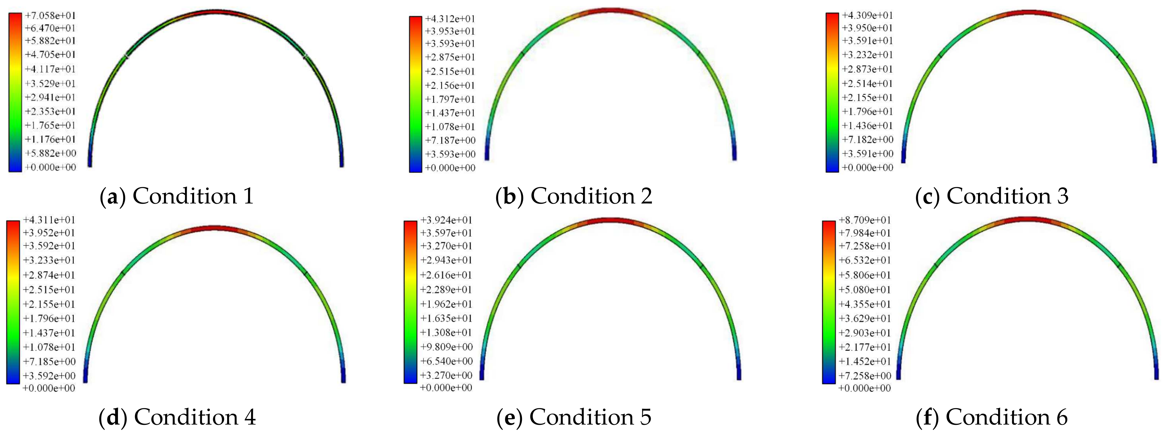
Using various joint diameters, the vertical displacements of A- and B-type snap-fit connected folding steel arch frames are illustrated in Figure 4. It can be observed that the deformation settlement of folding steel arch frames under surrounding rock pressure is not influenced by the type of snap-fit, exhibiting a symmetrical distribution with maximum vertical displacement at the arch crown, gradually decreasing towards both sides of the arch feet. The maximum vertical displacements for folding steel arch frames with A- and B-type snap-fit connections under different joint diameters are 70.6 mm, 43.1 mm, and 43.1 mm, and 43.1 mm, 39.2 mm, and 87.1 mm, respectively. The maximum vertical displacement of folding steel arch frames is significantly influenced by the snap-fit type and joint diameter. When the joint diameter does not exceed 20 mm, the maximum vertical displacement of both A- and B-type snap-fit steel arch frames decreases with increasing joint diameter. Moreover, the maximum displacement of B-type folding steel arch frames is noticeably smaller than that of A-type folding steel arch frames. This is attributed to the increase in stiffness at the snap-fit joint due to the larger elastic joint diameter and the greater number of joints, resulting in a gradual reduction in the arch crown settlement of folding steel arch frames. Therefore, within the joint diameter range of no more than 20 mm, B-type snap-fit effectively enhances the load-bearing capacity of the folding steel arch frame, demonstrating advantages in controlling arch deformation and reducing surrounding rock settlement. However, when the joint diameter exceeds 20 mm, A- and B-type snap-fit folding steel arch frames exhibit varying degrees of increased maximum vertical displacement with larger joint diameters. Additionally, the maximum displacement of B-type folding steel arch frames is significantly greater than that of A-type folding steel arch frames. This analysis suggests that when the joint diameter and quantity surpass certain values, they may weaken the strength and stiffness of the snap-fit connecting plates, leading to an increase in folding steel arch frame settlement, which is unfavorable for surrounding rock stability.
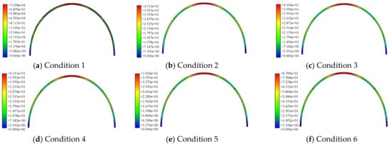
Figure 4.
Deformation of A- and B-type snap-fit folding steel arch frames.
As shown in Figure 5, the vault settlement of Type A and Type B snap-fit connected folding steel arch frames under different joint diameters exhibits the following patterns. For Type A, the vault settlement decreases with increasing joint diameter, but when the diameter exceeds 20 mm, further diameter variations show negligible effects on settlement. This occurs because the enlarged flexible joints enhance the stiffness at snap-fit connections, thereby reducing settlement, yet beyond 20 mm diameter, additional increments no longer significantly affect joint stiffness. For Type B, when the joint diameter is below 20 mm, the vault settlement decreases with increasing diameter due to improved strength and stiffness at snap-fit connections; however, diameters exceeding 20 mm conversely increase settlement, primarily because Type B contains more flexible joints than Type A, and oversized diameters (>20 mm) weaken the strength and stiffness of snap-fit connection plates.
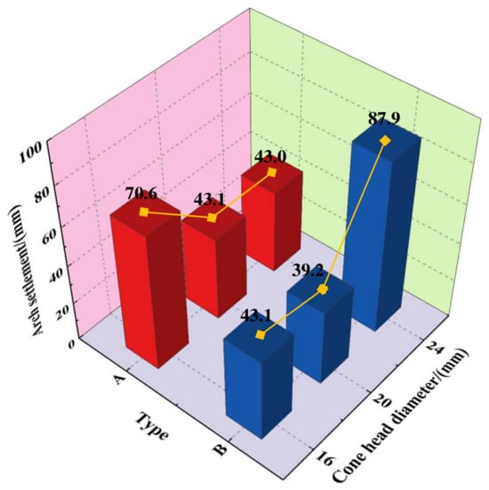
Figure 5.
Arch settlement of A- and B-type snap-fit folding steel arch frames.
3.3.2. Stress Characteristics of the Folding Steel Arch Frame
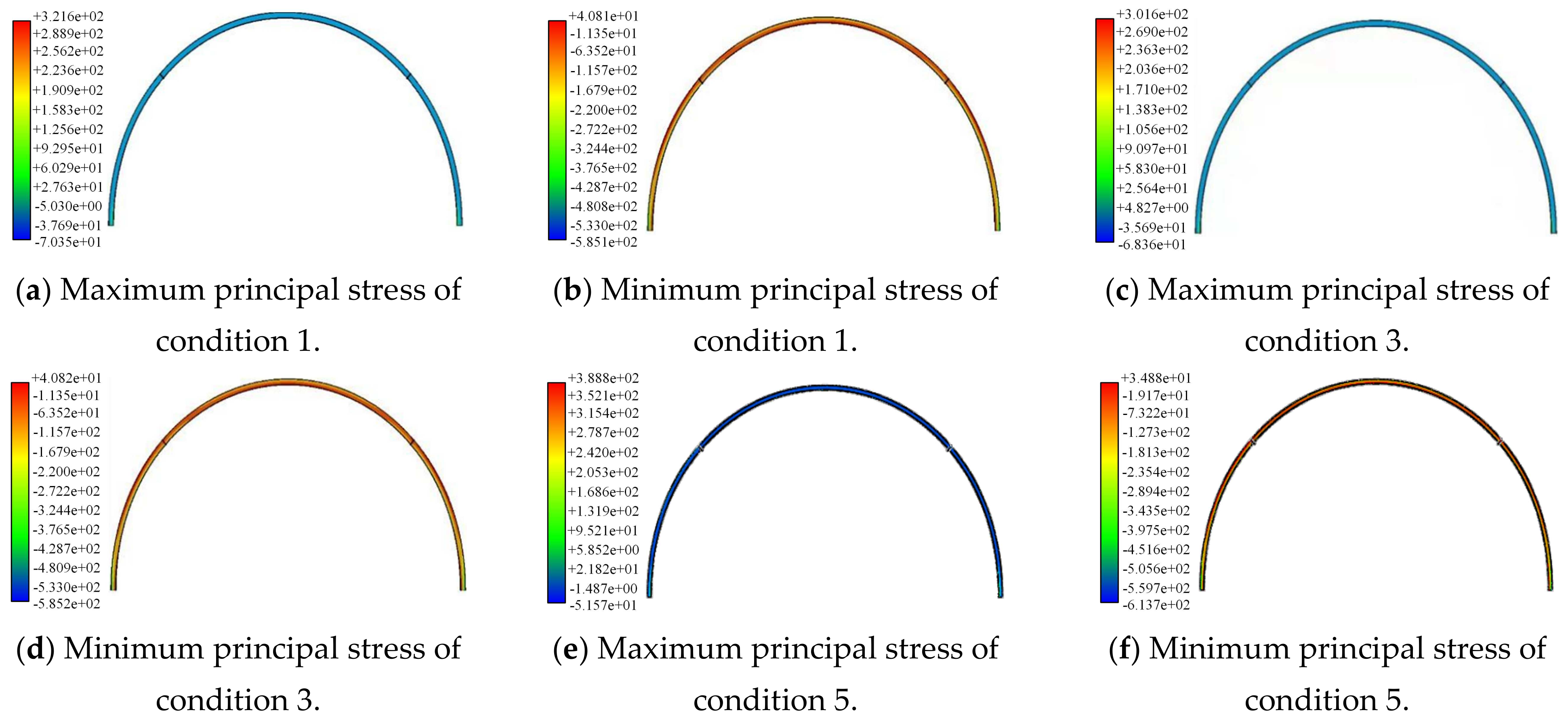
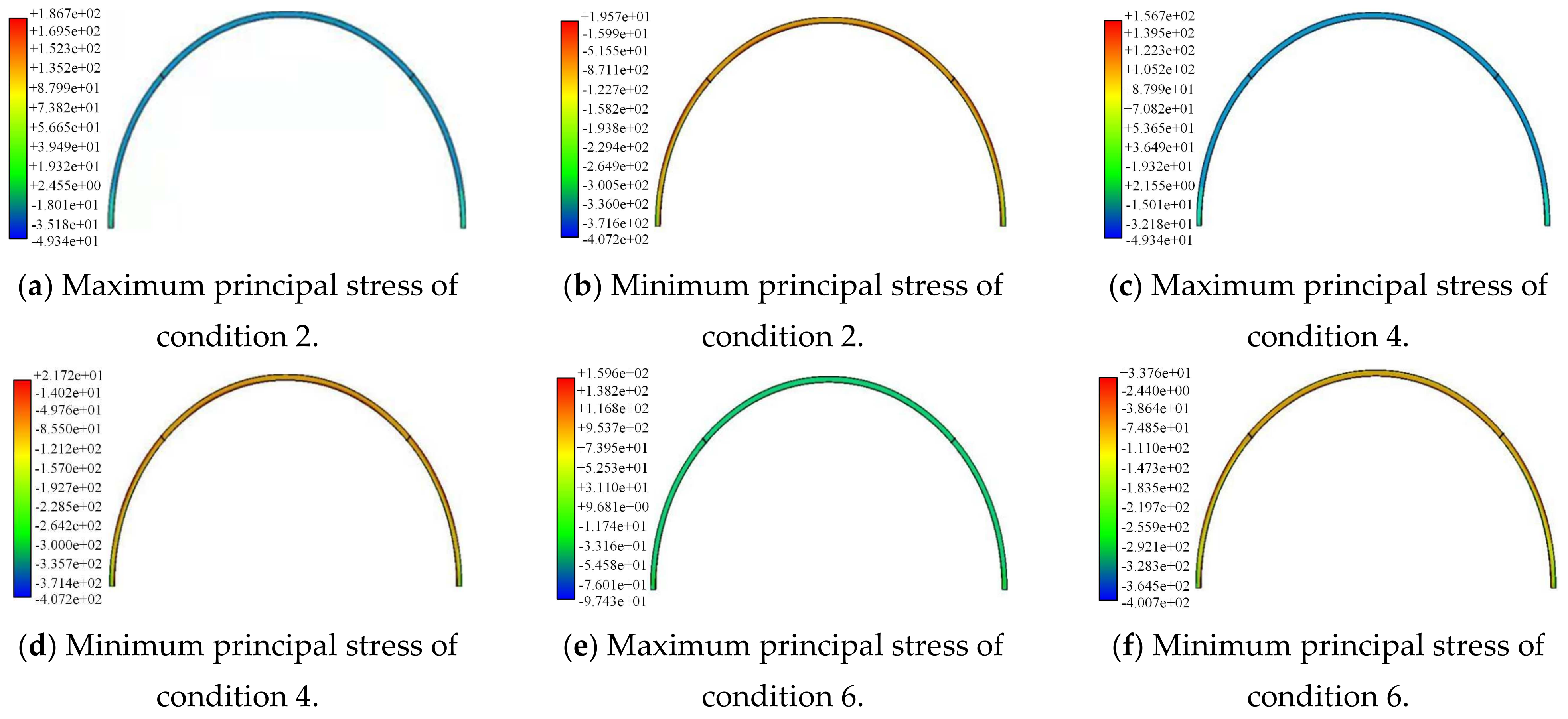
The stress distribution of folding steel arch frame structures with A- and B-type connectors under different elastic joint diameters is illustrated in Figure 6 and Figure 7, respectively. As depicted in the figures, it is evident that the maximum stresses in folding steel arch frames with various elastic joint diameters and quantities exhibit a symmetrical distribution, with compression being the primary stress. The highest compressive stress occurs at the crown, gradually decreasing towards the left and right arch feet. Notably, stress concentrations are predominantly localized at the arch feet positions. Therefore, reinforcement at the arch feet positions is essential during the erection process of folding steel arch frames to prevent structural damage at these locations, ensuring the overall load-bearing performance of the arch. When the type of snap-fit is constant, the maximum principal stresses in A-type folding steel arch frames show a negative correlation with the increase in elastic joint diameter.

Figure 6.
Principal stresses of the A-type snap-fit folding steel arch frame.

Figure 7.
Principal stresses of the B-type snap-fit folding steel arch frame.
The values are 70.4 MPa, 68.4 MPa, and 51.6 MPa, indicating the enhanced load-bearing capacity of A-type steel arch frames with increasing joint diameter. For B-type folding steel arch frames, when the joint diameter is below 20 mm, the maximum principal stress remains relatively stable at 49.3 MPa. However, when the joint diameter exceeds 20 mm, a noticeable increase in the maximum principal stress is observed, reaching 97.4 MPa. This increase may be attributed to the adverse effects of excessively large joint diameters on the strength of the connecting plates, resulting in a decline in the load-bearing capacity of the folding steel arch frame.
Furthermore, with equivalent elastic joint diameters, the B-type snap-fit folding steel arch frames consistently exhibit significantly lower maximum principal stresses compared to A-type snap-fit folding steel arch frames, showcasing superior resistance to deformation and load-bearing capacity. Consequently, the safety of the support structure is enhanced. In conclusion, the B-type snap-fit with a joint diameter of 20 mm demonstrates outstanding mechanical performance, positioning it as an ideal form of connection for folding steel arch frames.
3.3.3. Stress Characteristics of Joints
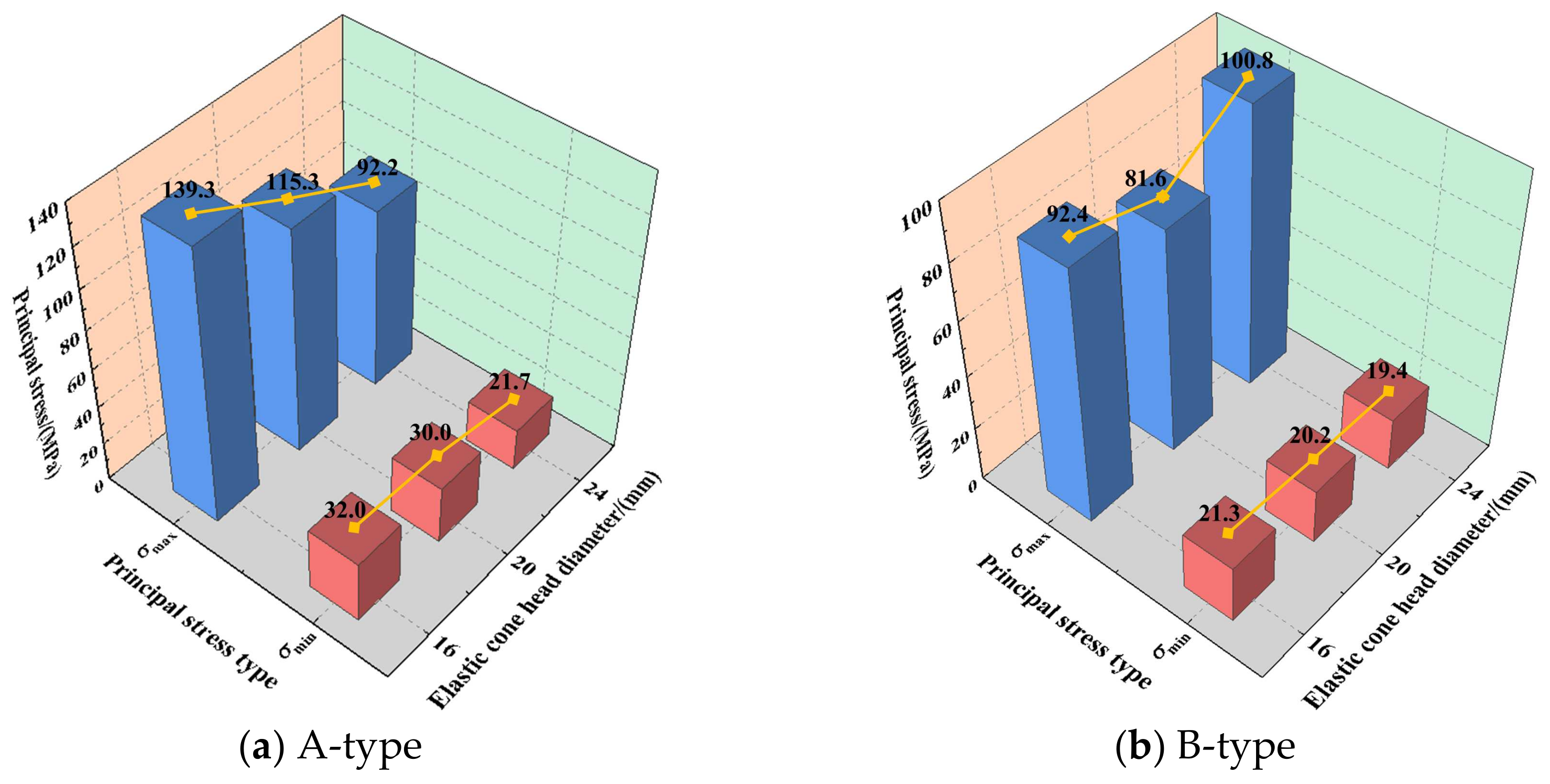
The principal stress of the A-type elastic joint with different joint diameters is shown in Figure 8. As illustrated in the figure, the principal stress concentration occurs mainly in the root area where the elastic joint contacts the connecting plate, predominantly experiencing tensile stress. Among the different joint diameters, the elastic joint with a diameter of 16 mm exhibits the highest maximum principal stress, reaching 139.3 MPa, while the elastic joint with a diameter of 24 mm shows the lowest maximum principal stress at 92.2 MPa.
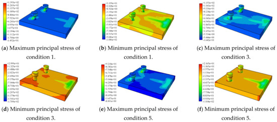
Figure 8.
Principal stress of the A-type elastic joint.
The principal stress of the B-type elastic joint is shown in Figure 9. Similar to the A-type snap-fit joints, stress concentration is mainly observed at the connection point between the elastic joint and the connecting plate.
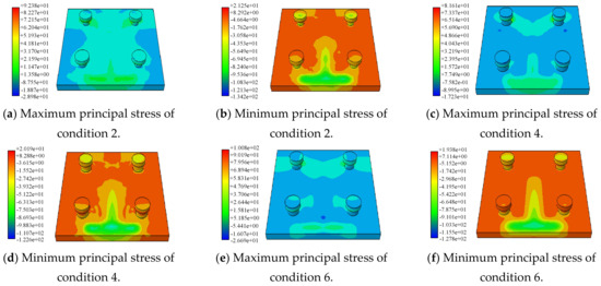
Figure 9.
Principal stress of the B-type elastic joint.
However, with an incremental increase in elastic joint diameter, the stress in the elastic joint decreases initially and then increases. The elastic joint with a diameter of 24 mm exhibits the highest maximum principal stress at 100.8 MPa, while the one with a 20 mm diameter corresponds to the lowest maximum principal stress at 81.6 MPa. In comparison to A-type snap-fit connections, tensile stress remains predominant in elastic joints; however, the maximum principal stress values at the stress concentration sites in the elastic joints experience a certain degree of reduction.
By extracting the maximum and minimum principal stresses of A-type and B-type snap-fit flexible joints under different working conditions, variation patterns can be obtained, as shown in Figure 10. As depicted in Figure 10a, the maximum principal stress of A-type snap-fit connections decreases gradually as the joint diameter increases. Furthermore, from a force perspective of flexible joints, increasing the joint diameter can effectively enhance the safety and resistance to damage of the snap-fit joint. Regarding the minimum principal stress, the change in joint diameter has a more significant impact on its maximum principal stress. When the joint diameter increases from 16 mm to 24 mm, the maximum principal stress decreases by 47.2 MPa, representing a reduction of approximately 33.8%. However, the rate of decrease in the maximum principal stress diminishes when the joint diameter exceeds 20 mm. By extracting the maximum and minimum principal stresses of B-type snap-fit flexible joints and analyzing the influence of different joint diameters on the principal stresses, we can observe a trend in their variation, as shown in Figure 10b. The maximum principal stress of B-type snap-fit connections exhibits a trend of initially decreasing and then increasing with the increase in joint diameter. This phenomenon is attributed to the fact that an excessively large joint diameter can alter the strength and stiffness of the connecting plate where the joint is located, thereby weakening the overall connection effect of the snap-fit assembly. When the joint diameter is 20 mm, the maximum principal stress of B-type snap-fit connections reaches its minimum value of 81.6 MPa.
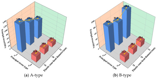
Figure 10.
Principal stress of the A-type and B-type elastic joints.
3.3.4. Contact Status Analysis of Connecting Plates
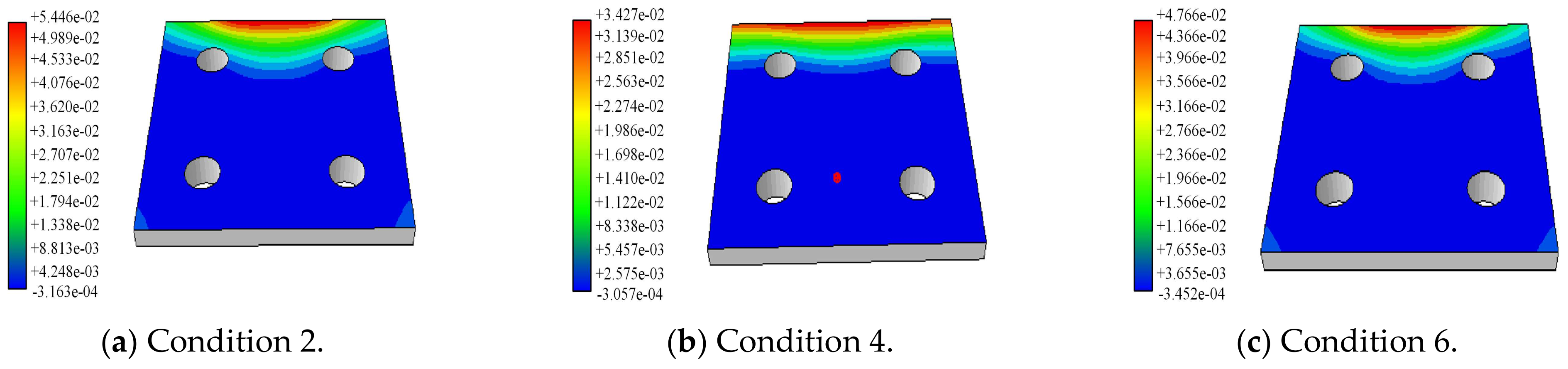
The displacement of the connecting plates can serve as an indicator of the contact state between the two plates, as illustrated in Figure 11 and Figure 12. Figure 11 reveals that in the A-type snap-fit connection, there is mutual compression between the connecting plates near the inner arc side of the tunnel, with no apparent trend of detachment. The separation zone of the connecting plates is primarily concentrated on the outer arc side closer to the surrounding rock. With the increase in the joint diameter, the displacement of the separation site of the connecting plates gradually decreases. This indicates that the spacing between the connecting plates gradually reduces as well. This indicates a gradual reduction in the detachment between the connecting plates and a decreased likelihood of compression failure. When the elastic joint diameter exceeds 20 mm, there is a certain alteration in the contact area of the connecting plates, but the impact on the detachment distance between the plates becomes less pronounced.
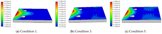
Figure 11.
Contact state between the snap-fit connecting plates of Type A.

Figure 12.
Contact state between the snap-fit connection plates of Type B.
The contact status between the connecting plates of the B-type snap connection device under different joint diameters is shown in Figure 12. The extrusion area between the connecting plates is mainly concentrated on the inner arc side close to the tunnel, and the disengagement area between the connecting plates is mainly concentrated on the outer arc side close to the surrounding rocks. However, in comparison to A-type snap-fit connection assemblies, the detachment distance between the connecting plates is significantly reduced. For B-type snap-fit connection assemblies, with the increase in elastic joint diameter, the detachment distance between connecting plates decreases initially and then increases. When the joint diameter is 20 mm, the minimum detachment distance between the connecting plates is observed. However, as the joint diameter increases to 24 mm, both the detachment area and distance increase. This suggests that exceeding a specific value of elastic joint diameter weakens the stiffness and strength of the connecting plates.
The above analysis concludes that B-type snap-fit connections exhibit better control over surrounding rock deformation while experiencing lower stress levels. The stress concentration at the connection site and the detachment distance between connecting plates are both minimized, indicating that the comprehensive performance of B-type snap-fit connections in folding steel arch frames is superior to that of A-type snap-fit connections. Furthermore, the load-bearing capacity of the B-type snap-fit connection, particularly that with an elastic joint diameter of 20 mm, surpasses that of other sizes of connectors, making it more suitable for use in machining folding steel arch frame structures with snap-fit connections.
4. Engineering Application and Verification
4.1. Project Overview
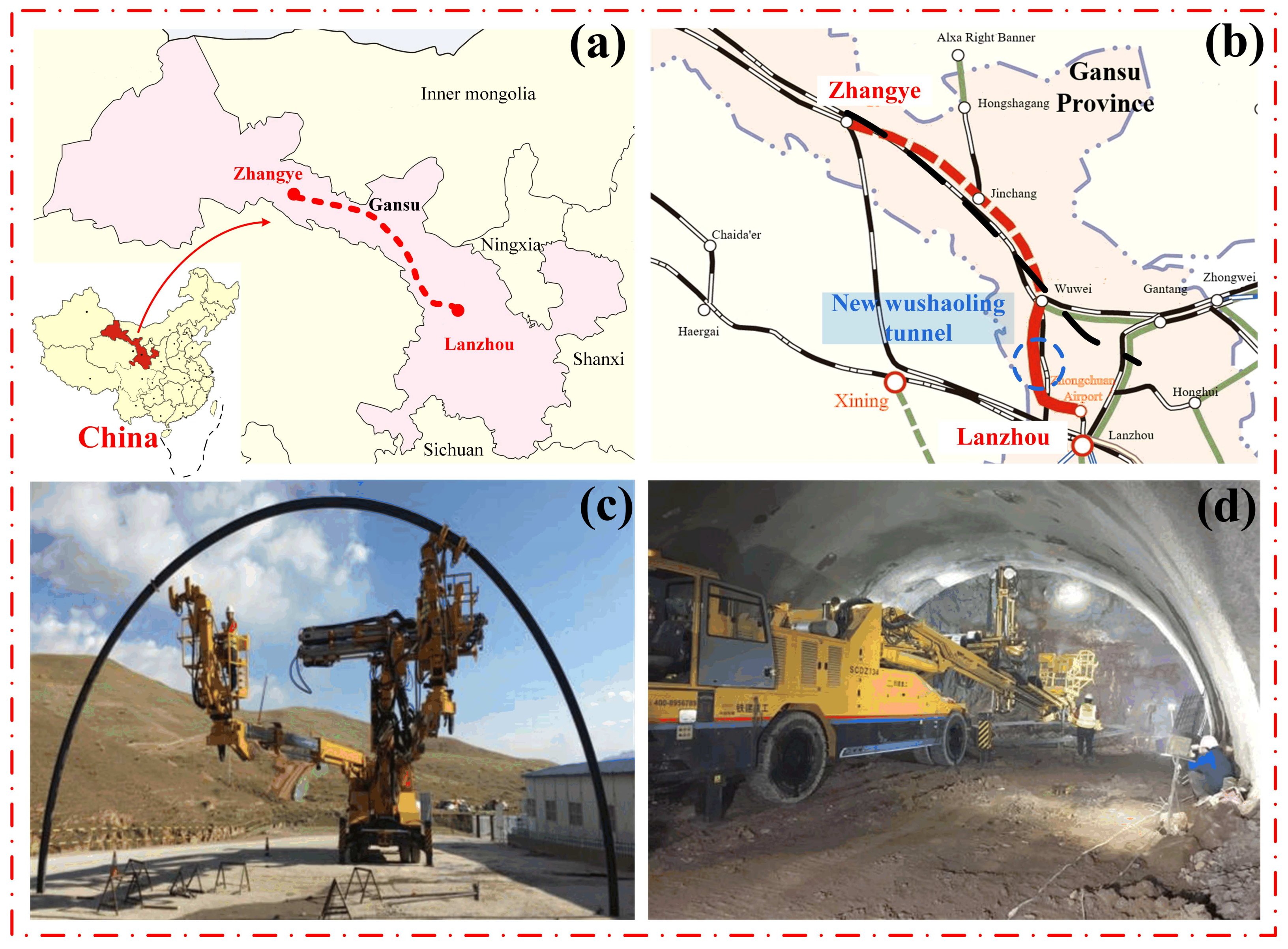
The New Wushaoling tunnel is a pivotal project in the construction of the Lanzhou to Zhangye No. 3 and No. 4 Line Railway, specifically the Chuan Airport to Wuwei section. Positioned to the east of the existing Lanzhou–Wuwei No. 2 Line’s Wushaoling Extra-Long Tunnel, the tunnel is approximately 210 m and 571 m away from the existing right-line tunnels at the Zhangye and Lanzhou ends, respectively. The rail’s surface elevation is approximately 36 m higher at the Zhangye end and 110 m higher at the Lanzhou end compared to the Zhangye end of the existing Wushaoling Extra-Long Tunnel. This newly designed tunnel is a double-track railway tunnel with a design speed of 250 km/h (see Figure 13). Situated in Dachaigou Town, Tianzhu County, at the entrance and in Anyuan Town at the exit, the tunnel traverses the Wushaoling Mountain range. It spans from DK160+920 to DK178+045, with a maximum burial depth of 952 m and a total length of 17,125 m. The geological conditions comprise 3275 m of Class III surrounding rock, accounting for 19.12%; 6680 m of Class IV surrounding rock, constituting 39.01%; and 7275 m of Class V surrounding rock, making up 41.87%. To address challenges such as high erection risks, intensive labor requirements, and low erection precision associated with the erection of folding steel arch frames in the tunnel, from October 2020 to March 2021, the China Railway 15th Bureau Group Fifth Engineering Co., Ltd. conducted a research trial for tunnel machining arch frame erection in the entrance section of the New Wushaoling tunnel, spanning DK160+920 to DK168+941. The average burial depth of the trial section is 450 m, and the geological conditions are complex, featuring exposures of sedimentary, igneous, and metamorphic rocks, with sedimentary rocks being predominant.
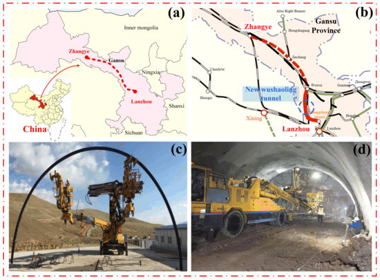
Figure 13.
Folding steel arch frame machining erection test in New Wushaoling tunnel: (a) Lanzhou to Zhangye No. 3 and No. 4 Line Railway; (b) New Wushaoling tunnel; (c) splicing outside the tunnel; (d) erection inside the tunnel.
4.2. Result Analysis
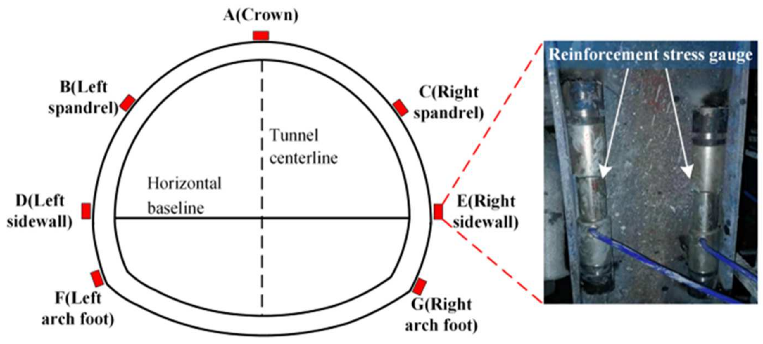
To avoid the influence of irrelevant factors, two representative sections with favorable subsurface conditions and similar characteristics were selected for the mechanical arch construction test at the import site. These sections are located at the monitoring faces DK162+100 and DK162+105, with a burial depth of 260 m and IV surrounding rock. The arch construction was carried by opening excavation at the monitoring faces. Two arch frames were constructed using the mechanical arch method at the monitoring faces, namely an A-type snap-fit connection folding steel arch frame (hereinafter referred to as the A-type steel arch) at the DK162+100 monitoring face and a B-type snap-fit connection folding steel arch frame (hereinafter referred to as the B-type steel arch) at the DK162+105 monitoring face. Monitoring points were set at key positions along the excavation profile and installed at seven measurement points on the monitoring faces, as shown in Figure 14. From top to bottom, these points include the arch crown, left and right spandrels, left and right sidewalls, and left and right arch feet. The installation of the field measurement instruments is shown in Figure 14, with TZX-R-type tension steel strain gauges installed on both sides of the steel arch rib plate. The changes in the steel arch’s vibrational frequency after loading are recorded daily to measure the dynamic rules of steel arch axial loading. Due to the axial symmetry of steel arch loading, only the mechanical responses of the two steel arches at the arch crown, left spandrels, left sidewalls, and left arch feet are compared in this section for analysis.

Figure 14.
Measurement point layout of the tunnel monitoring section.
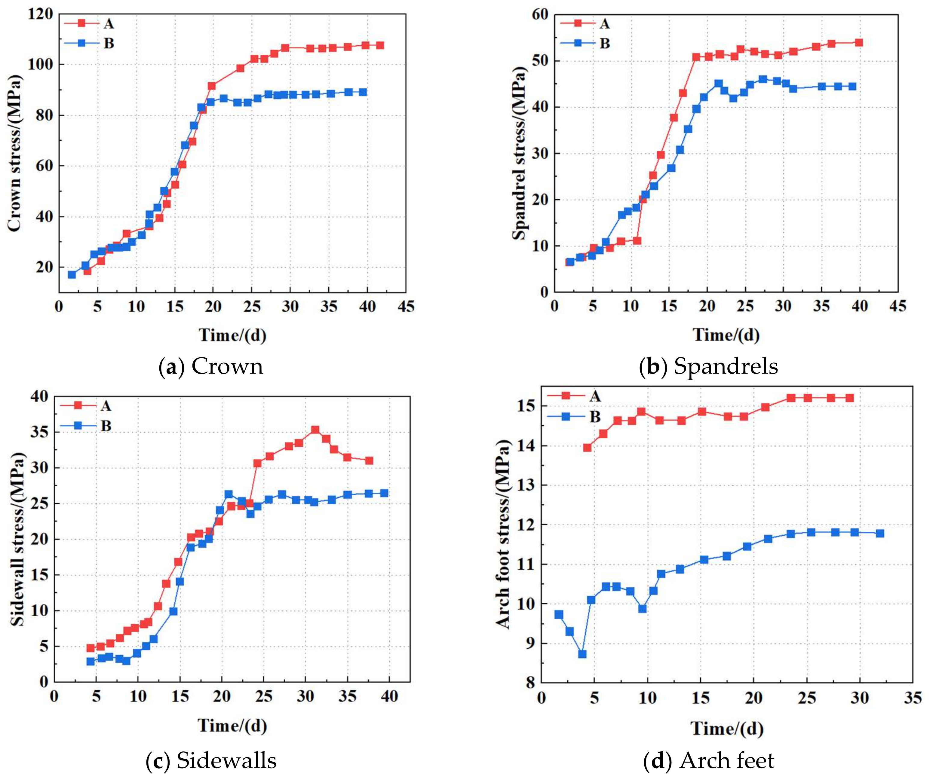
Figure 15 shows stress monitoring curves for the steel arch frames. The two types of steel arch frames exhibited the maximum stress values at the crown of the arch due to the key node effect, as the crown is the primary load-bearing point. Both A-type and B-type steel arch frames showed significant differences in axial stress at the crown, arch soffit, sidewall, and arch springing; the A-type steel arch frames exhibited higher stress levels compared to the corresponding components of the B-type steel arch frames, indicating that under similar conditions, the A-type steel arch frames experience greater axial stress, while the B-type steel arch frames demonstrated better support performance with lower overall stress levels. The axial stress changes in both steel arch frames exhibited similar trends over time, but the A-type steel arch frames showed a higher rate of stress increase. The stress at the crown of the steel arch frames gradually reached values close to 25 MPa before stabilizing briefly, followed by a rapid increase from the 10th to the 20th day. This trend was closely associated with the progress of the lower bench excavation. Before the 10th day, the stress changes at the crown of the steel arch frames were relatively small, primarily due to the diminishing influence of the creation of the construction face. However, after the 10th day, the stress increase rate in the steel arch frames became significantly larger, indicating that the lower bench excavation had a greater influence on the axial stress of the steel arch frames at the crown. Additionally, the A-type steel arch frames showed higher rates of stress increase compared to the B-type steel arch frames at the arch soffit and sidewall, while the B-type steel arch frames exhibited a higher rate of stress increase at the sidewall compared to the A-type steel arch frames. However, after the stress stabilized, the A-type steel arch frames showed higher stress levels in all components compared to the corresponding components of the B-type steel arch frames. These differences further indicate that under similar conditions, the A-type steel arch frames experience greater axial stress, while the B-type steel arch frames demonstrate better support performance with more reasonable axial stress distribution, reduced concentration of stresses on the connection plates, and improved overall load-bearing capacity and safety. This result further validates the stability and reliability of the B-type snap-fit connection folding steel arch frames under large loads and complex construction conditions, providing effective support for the redistribution of stresses caused by removal of load during bench excavation, thereby effectively controlling rock deformation. This makes the B-type snap-fit connection folding steel arch frame an ideal choice for optimizing the structure of folding steel arch frames.
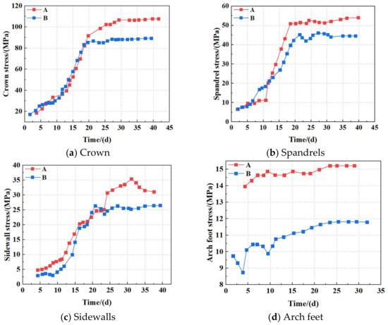
Figure 15.
Stress–time history curve of steel arch at various measuring points.
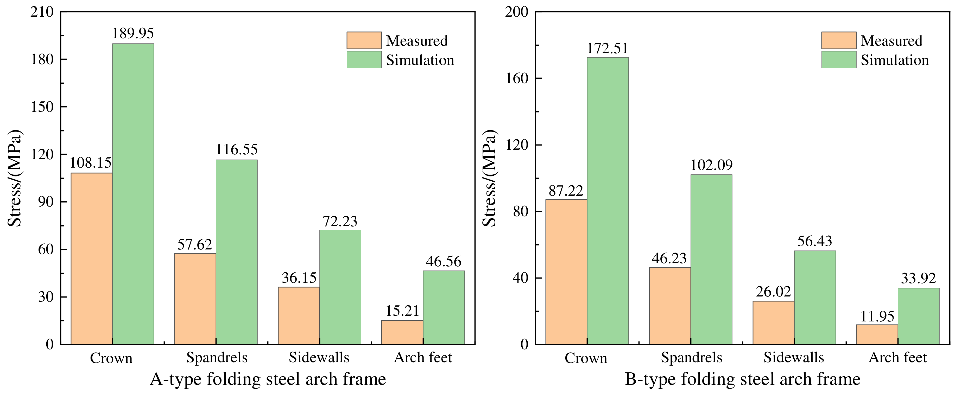
Based on experimental data, a comparative analysis was conducted between the A-type and B-type steel arch frames regarding the stress values measured at the arch crown, spandrel, sidewall, and arch foot. The results (Figure 16) indicate that regardless of the type of connection, the numerical simulation results consistently exceeded the measured values, likely due to delays in steel arch installation after excavation, allowing the surrounding rock to release some energy. However, both the numerical simulation and field monitoring results showed similar trends in terms of stress changes. Additionally, the B-type steel arch frames exhibited lower stress levels at all components compared to the corresponding components of the A-type steel arch frames. This result is primarily attributed to the B-type snap-fit connection, which results in more uniform stress distribution and reduces the concentration of stresses on the connection plates, thereby improving the overall load-bearing capacity and safety of the steel arch frames. These findings further validate the stability and reliability of the B-type snap-fit connection folding steel arch frames under large loads and complex construction conditions. The B-type steel arch frames are capable of providing strong support for the redistribution of stresses caused by the removal of loads during bench excavation, effectively controlling rock deformation. As a result, the B-type snap-fit connection folding steel arch frame represents an optimal choice for optimizing the structure of folding steel arch frames.
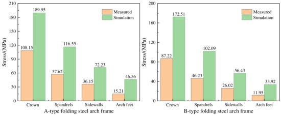
Figure 16.
Comparison of field test and simulation results.
5. Recommendations
In order to meet the requirements for “unmanned” construction of arch spans in tunnels, this study investigated the load characteristics of folding steel arch frames with different snap-fit connection types. Although certain achievements have been made, there are still some limitations and shortcomings, detailed as follows.
(1) The study of the load characteristics of the folding steel arch frame did not consider the planar bending and twisting deformation of the steel arch frame.
(2) When establishing the finite element model, due to the greater burial depth of the tunnel, the load equivalent of the upper rock mass was used without considering the effects of construction stresses, dynamic loads, and fatigue loads, leading to some discrepancies compared to the actual situation.
(3) Due to limited monitoring points and environmental factors under actual construction conditions, it is difficult to comprehensively simulate long-term performance. Additionally, the simulation model’s complexity in material models and joint failure mechanisms led to certain simplifications, which may not fully reflect the actual complex conditions.
It is recommended that in future research, experimental conditions are expanded to study the load stability of folding steel arch frames under different working conditions; the finite element model be improved by developing more precise material models and joint failure mechanism models. Long-term testing and actual application monitoring could be conducted to evaluate long-term performance and efforts made to promote the development and application of mechanized tunnel installation technologies.
6. Conclusions
This study is based on the excavation compensation concept and combines numerical simulation with field testing to investigate the effects of different snap-fit connections on the load characteristics of folding steel arch frames in tunnels. The main conclusions are as follows.
- The maximum vertical displacements of A- and B-type snap-fit connections decrease and then increase with increasing joint diameter. With a joint diameter of 20 mm, the minimum displacements are 43.1 mm and 39.2 mm, respectively, for A- and B-type snap-fit connections. The vertical displacement of the B-type snap-fit is reduced by 9.1% compared to the A-type snap-fit, indicating that the B-type snap-fit has stronger anti-deformation capacity and greater load-bearing performance.
- The maximum principal stress of the B-type folding steel arch frames is 49.3 MPa, which is 4.5% lower than that of the A-type folding steel arch frames (51.6 MPa).
- The field test results indicate that for the same joint diameter, the maximum stress of the B-type folding steel arch frames is reduced by 15.8% compared to the A-type folding steel arch frames, significantly improving their ability to compensate for rock deformation. This makes the B-type snap-fit a more suitable form of connection for folding steel arch frames in tunnels and facilitates the development and application of mechanized installation technologies for steel arch frames in tunnels.
Author Contributions
Conceptualization, S.L.; Methodology, S.L., C.H., X.Y., Z.T. and J.G.; Software, S.L., X.Y. and Z.T.; Formal analysis, J.G.; Investigation, C.H.; Writing—original draft, S.L. and C.H.; Writing—review & editing, S.L., C.H., X.Y., Z.T., J.G., H.L., T.Y. and J.H. All authors have read and agreed to the published version of the manuscript.
Funding
This research was funded by the National Natural Science Foundation of China—Railway Fundamental Research Joint Fund Project (U2468219); the Research and Development Projects of Science and Technology of China Railway Construction Co., Ltd. (Project No. N2020G040); the Science and Technology Research and Development Project of China Railway Construction Co., Ltd. (Project No. 2024-W25); and the China Association of Construction Enterprise Management (Grant No. 2023-B-028).
Data Availability Statement
Data will be made available on request.
Acknowledgments
The authors greatly appreciate financial support from various funding bodies and are grateful to the reviewers for their valuable comments and suggestions, which improved the quality of the paper.
Conflicts of Interest
Authors Shaohua Li, Humin Li and Tiejun Yao were employed by the company China Railway 15th Bureau Group Co., Ltd. The remaining authors declare that the research was conducted in the absence of any commercial or financial relationships that could be construed as a potential conflict of interest. The authors declare that this study received funding from China Railway Construction Co., Ltd. The funder was not involved in the study design, collection, analysis, interpretation of data, the writing of this article or the decision to submit it for publication.
References
- China Civil Engineering Society. Report on Advance in Tunnel and Underground Engineering; Science and Technology of China Press: Beijing, China, 2020. [Google Scholar]
- Qian, Q.H.; Lin, P. Safety risk management of underground engineering in China: Progress, challenges and strategies. J. Rock Mech. Geotech. Eng. 2016, 8, 423–442. [Google Scholar] [CrossRef]
- Guo, D.S.; Song, Z.P.; Xu, T.; Zhang, Y.W.; Ding, L.B. Coupling analysis of tunnel construction risk in complex geology and construction factors. J. Constr. Eng. Manag. 2022, 148, 04022097. [Google Scholar] [CrossRef]
- Gong, J.F.; Wang, W.; Li, X.; Zhu, Y. Statistics of railway tunnels in China by the end of 2022 and overview of key tunnels of projects newly put into operation in 2022. Tunn. Constr. 2023, 43, 721. [Google Scholar]
- Wang, Q.S. Some thoughts on development of drilling-and-blasting construction technology for mountain tunnels in China. Tunn. Constr. 2023, 43, 37–45. [Google Scholar]
- Wang, Q.; Qin, Q.; Jiang, B.; Xu, S.; Zeng, Z.N.; Luan, Y.C.; Liu, B.H.; Zhang, H.J. Mechanized construction of fabricated arches for large-diameter tunnels. Autom. Constr. 2021, 124, 103583. [Google Scholar] [CrossRef]
- He, Y.F.; Yang, M.; Xu, Z.; Li, S.Y.; Zhang, B.W. Design of tunnel steel arch looping manipulator with multiple actuators in limited space. Sci. Prog. 2023, 106, 368504231180025. [Google Scholar] [CrossRef]
- Tao, Z.G.; Xie, D.; Sui, Q.R.; Sun, J.H.; He, M.C. Study on active support method and control effect of NPR anchor cables for large deformation of tunnel surrounding rock under complex geological conditions. Chin. J. Rock Mech. Eng. 2024, 43, 275–286. [Google Scholar]
- Sui, M.C.H.Q.R.; Tao, Z.G. Excavation compensation theory and supplementary technology system for large deformation disasters. Deep. Undergr. Sci. Eng. 2023, 2, 105–128. [Google Scholar] [CrossRef]
- Guo, L.J.; Tao, Z.G.; He, M.C.; Coli, M. Excavation compensation and bolt support for a deep mine drift. J. Rock Mech. Geotech. Eng. 2024, 16, 3206–3220. [Google Scholar] [CrossRef]
- Guo, J.B.; Chen, J.; Liu, J.Z.; Niu, J.C. Multifunctional integration equipment design and construction technology research. Adv. Mater. Res. 2013, 650, 359–363. [Google Scholar] [CrossRef]
- Cheng, Y. The Research of Trajectory Planning for Manipulator of SGDC700 Tunnel Arch Multi-Function Installing Truck. Master’s Thesis, Xiangtan University, Xiangtan, China, 2015. [Google Scholar]
- Wang, Q. Control Theory and Engineering Practice of Confined Concrete in Underground Engineering; Science Press: Beijing, China, 2019. [Google Scholar]
- Liu, F.X. SCDZ133 intelligent multi-function trolley and its application in tunneling. Mod. Tunn. Technol. 2019, 56, 1–7. [Google Scholar]
- Sun, H.L. Study on Stability Bearing Mechanism and Key Technologies of Assembly Confined Concrete Support for Large Section Tunnel. Master’s Thesis, Shandong University, Jinan, China, 2020. [Google Scholar]
- He, Y.F.; Xia, Y.M.; Long, B.; Deng, Z.H.; Lei, M.L.; Yao, J. Grasping docking mechanism of TBM steel arch splicing robot. J. Zhejiang Univ. (Eng. Sci.) 2021, 54, 2204–2213. [Google Scholar]
- Zhao, Y. Subsidiary technology for rapid construction of multifunctional steel arch erection machine in Yuelongmen tunnel. Railw. Constr. Technol. 2020, 2, 96–98+132. [Google Scholar]
- Yan, Q. A remote unmanned construction system for steel arch erection developed by Japan Toda Construction Corporation. Tunn. Constr. 2021, 41, 387. [Google Scholar]
- Krauze, K.; Boloz, L.; Mucha, K.; Wydro, T. The mechanized supporting system in tunnelling operations. Tunn. Undergr. Space 2021, 113, 103929. [Google Scholar] [CrossRef]
- Ni, P.L. Research and application of new type of tunnel supporting equipment, steel arch installation trolley. China Plant Eng. 2020, 18, 12–13. (In Chinese) [Google Scholar]
- Sun, C.Z.; Miao, C.Q.; Li, A.Q.; Qian, Y. Finite element analysis of mechanical properties of pile cap connections for prestressed concrete solid pile using snap-in mechanical connection. J. Disaster Prev. Mitig. Eng. 2019, 39, 37–44. [Google Scholar]
- Wang, J.B. Numerical Simulation of Bending and Large Deformation Retractable Steel Arch Frame Support in Layered Soft Rock Tunnel. Master’s Thesis, Chengdu University of Technology, Chengdu, China, 2020. [Google Scholar]
- Li, W.T.; Yang, N.; Mei, Y.C.; Zhang, Y.H.; Wang, L.; Ma, H.Y. Experimental investigation of the compression-bending property of the casing joints in a concrete filled steel tubular supporting arch for tunnel engineering. Tunn. Undergr. Space Technol. 2020, 96, 103184. [Google Scholar] [CrossRef]
- Xu, F.; Li, S.C.; Zhang, Q.Q.; Li, L.P.; Shi, S.S.; Zhang, Q. A new type support structure in-troduction and its contrast study with traditional support structure used in tunnel construction. Tunn. Undergr. Space Technol. 2017, 63, 171–182. [Google Scholar] [CrossRef]
- Ma, K.M.; Zhang, J.C.; Zhang, J.R.; Wang, Z.Y.; Feng, J.M. Longitudinal connection effect on initial support steel frames in tunnels—Take the traffic tunnels as examples. Undergr. Space 2022, 7, 608–622. [Google Scholar] [CrossRef]
- Song, Q.Y.; Heidarpour, A.; Zhao, X.L.; Han, L.H. Performance of flange-welded/web-bolted steel I-beam to hollow tubular column connections under seismic load. Thin Walled Struct. 2017, 116, 250–264. [Google Scholar] [CrossRef]
- Yue, G.Z. Some suggestions on the connection of steel arch frame in tunnel construction. J. Shandong Ind. Technol. 2015, 23, 86–87. (In Chinese) [Google Scholar] [CrossRef]
- Li, G.A.; Wang, Y.D.; Nie, Y.W.; Wan, S.T.; Wang, C.Y. Study on longitudinal connection support structure of steel plate between steel arches of soft rock tunnel. Highway 2022, 67, 411–418. (In Chinese) [Google Scholar]
- He, M.C.; Wang, B.; Tao, Z.G.; Qiao, Y.F.; Xiao, Y.M. Axial compression behavior of adaptive steel arch joint for large deformation tunnels. China J. Highw. Transp. 2021, 34, 1–10. [Google Scholar]
- Zhang, G.W.; Li, D.W.; Lei, X.T. Folding steel arch frame applicable to mechanized construction of tunnels and its key techniques. Tunn. Constr. 2022, 42, 445–450. [Google Scholar]
- Zhang, G.W. Study on Mechanical Effect of Connection Mode Between Segments of Steel Arch Frame Suitable for Unmanned Installation. Master’s Thesis, Lanzhou Jiaotong University, Lanzhou, China, 2022. [Google Scholar]
- Wu, Y.M.; Tian, C.Q.; Xu, P.; Zhao, Z.Z.; Zhang, J.W.; Wang, S.J. Design optimization method of feet-lock steel pipe for soft-rock tunnel based on load-deformation coordination. Appl. Sci. 2022, 12, 3866. [Google Scholar] [CrossRef]
- Huang, C.F.; Li, S.H.; Li, D.W.; Li, W.B.; Yao, T.J.; Xiao, Y. Mechanical properties of folding arch frame joints for unmanned arch erection. Buildings 2024, 14, 1480. [Google Scholar] [CrossRef]
- Liu, Z.Y.; Tang, Q.S.; Dong, X.Y.; Weng, W.S.; Zhao, J.X.; Zhang, J.M. Experimental study on performance of the connection joints of cold-formed square steel tubular columns and H-shaped steel beams extension endplate using blind bolts. Build. Struct. 2021, 51, 57–63. [Google Scholar]
- Wang, H.; Zheng, P.Q.; Zhao, W.J.; Tian, H.M. Application of a combined supporting technology with U-shaped steel support and anchor-grouting to surrounding soft rock reinforcement in roadway. J. Cent. South Univ. 2018, 25, 1240–1250. [Google Scholar] [CrossRef]
- TB 10003-2016; Code for Design of Railway Tunnel. Ministry of Railways: Beijing, China, 2016.


Disclaimer/Publisher’s Note: The statements, opinions and data contained in all publications are solely those of the individual author(s) and contributor(s) and not of MDPI and/or the editor(s). MDPI and/or the editor(s) disclaim responsibility for any injury to people or property resulting from any ideas, methods, instructions or products referred to in the content. |
© 2025 by the authors. Licensee MDPI, Basel, Switzerland. This article is an open access article distributed under the terms and conditions of the Creative Commons Attribution (CC BY) license (https://creativecommons.org/licenses/by/4.0/).