
Analytical and Numerical Investigation of Internal Force Distribution in “Pile-Wall” Structures Based on Finite Difference Method


Abstract
1. Introduction
2. Theoretical Derivation of the “Pile-Wall” Condition
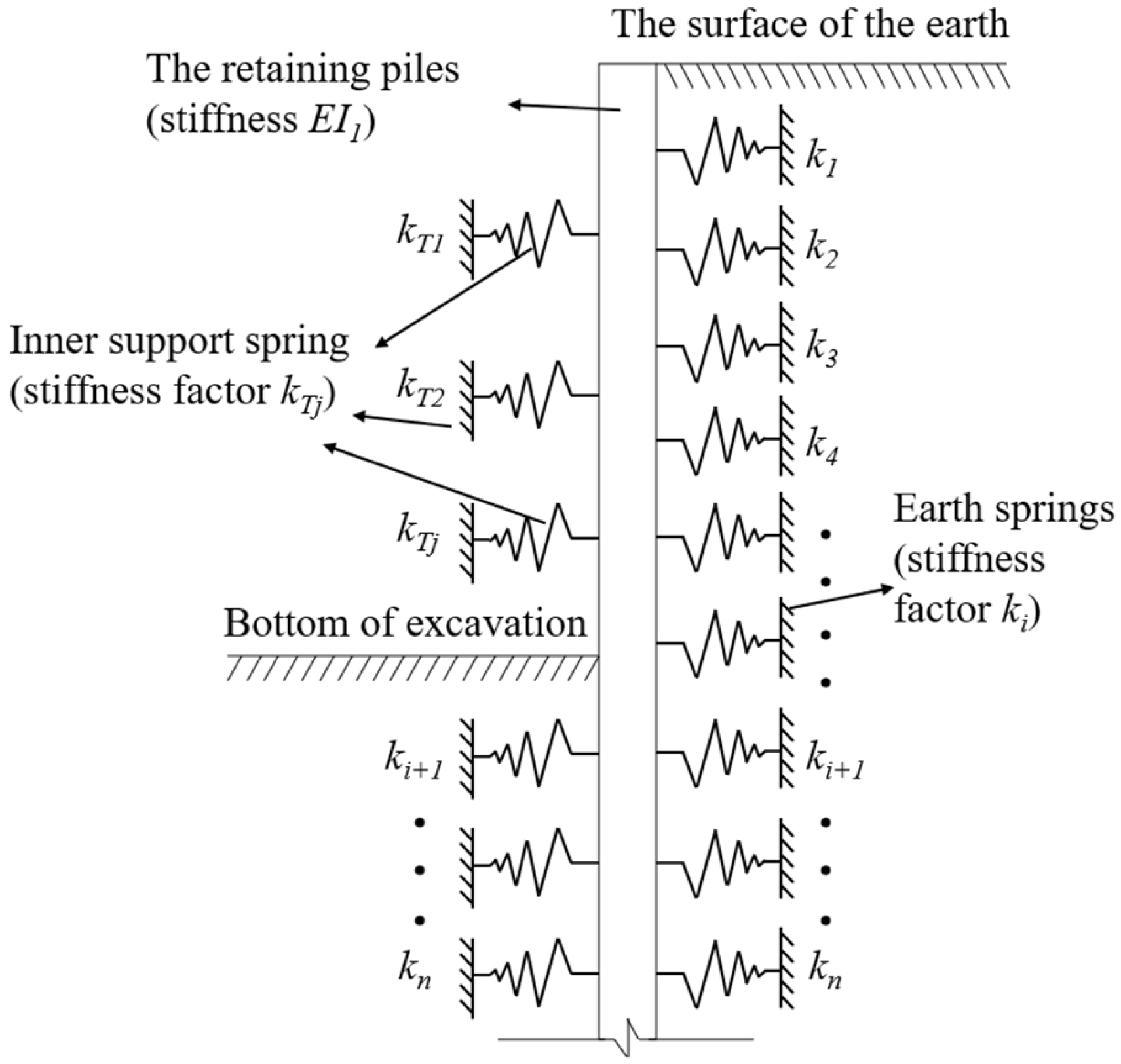
2.1. Calculation Assumption
- (1)
- The deformation between the soil and the retaining pile is coordinated without relative displacement;
- (2)
- The displacement of the inner support and the retaining pile is the same, and the deformation is coordinated;
- (3)
- The interaction between the retaining pile and its surrounding soil is replaced by the equivalent of soil spring.
2.2. Calculation of Excavation Conditions
2.3. Calculation of Construction Conditions
2.4. Analysis of Theoretical Derivation Results of Bending Moment
3. Overview of the Project and Introduction to Finite Element Modeling
3.1. Engineering Background
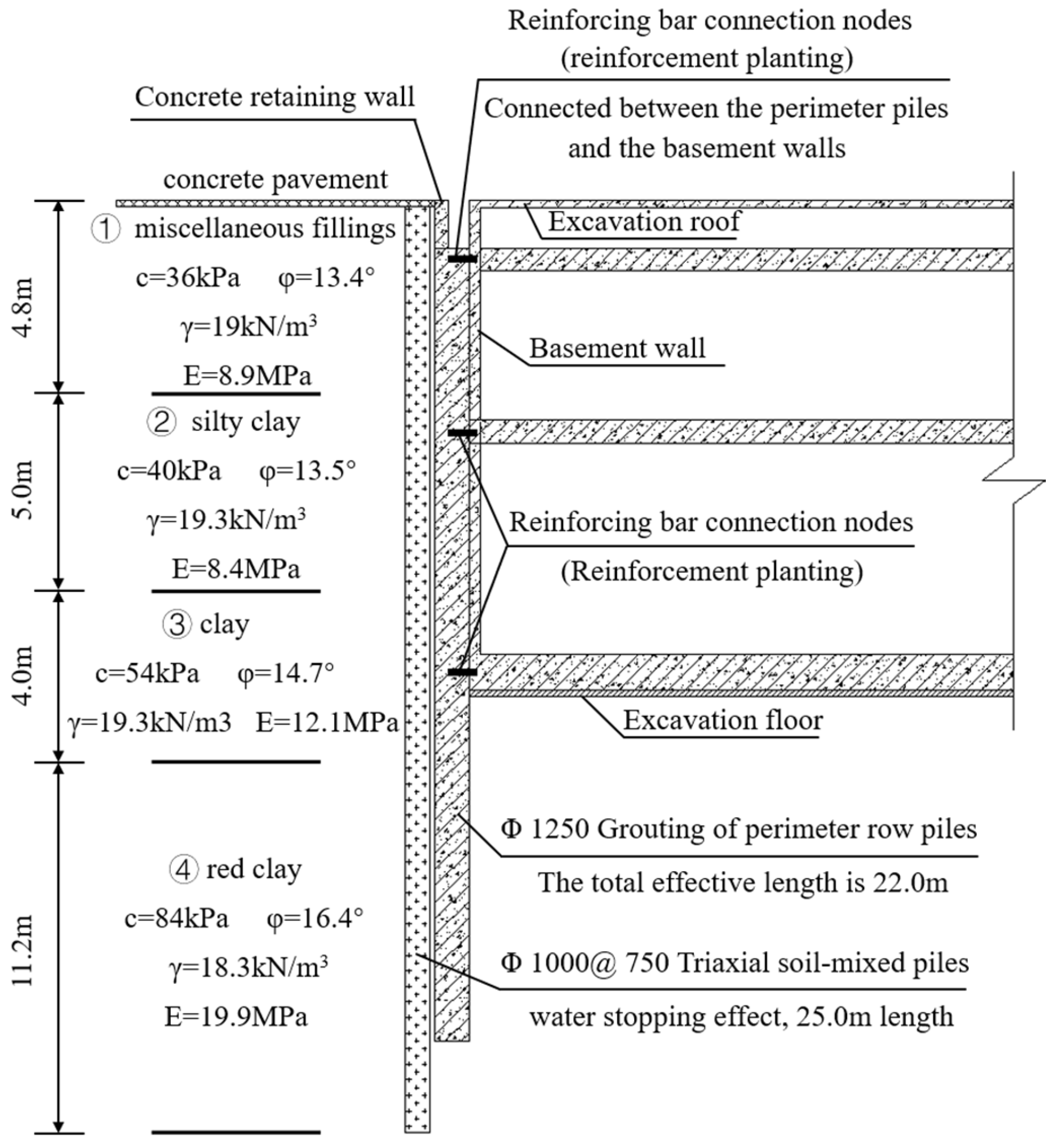
3.2. Engineering and Hydrogeologic
3.3. Finite Element Simulation Model
3.3.1. Intrinsic Modeling and Parameter
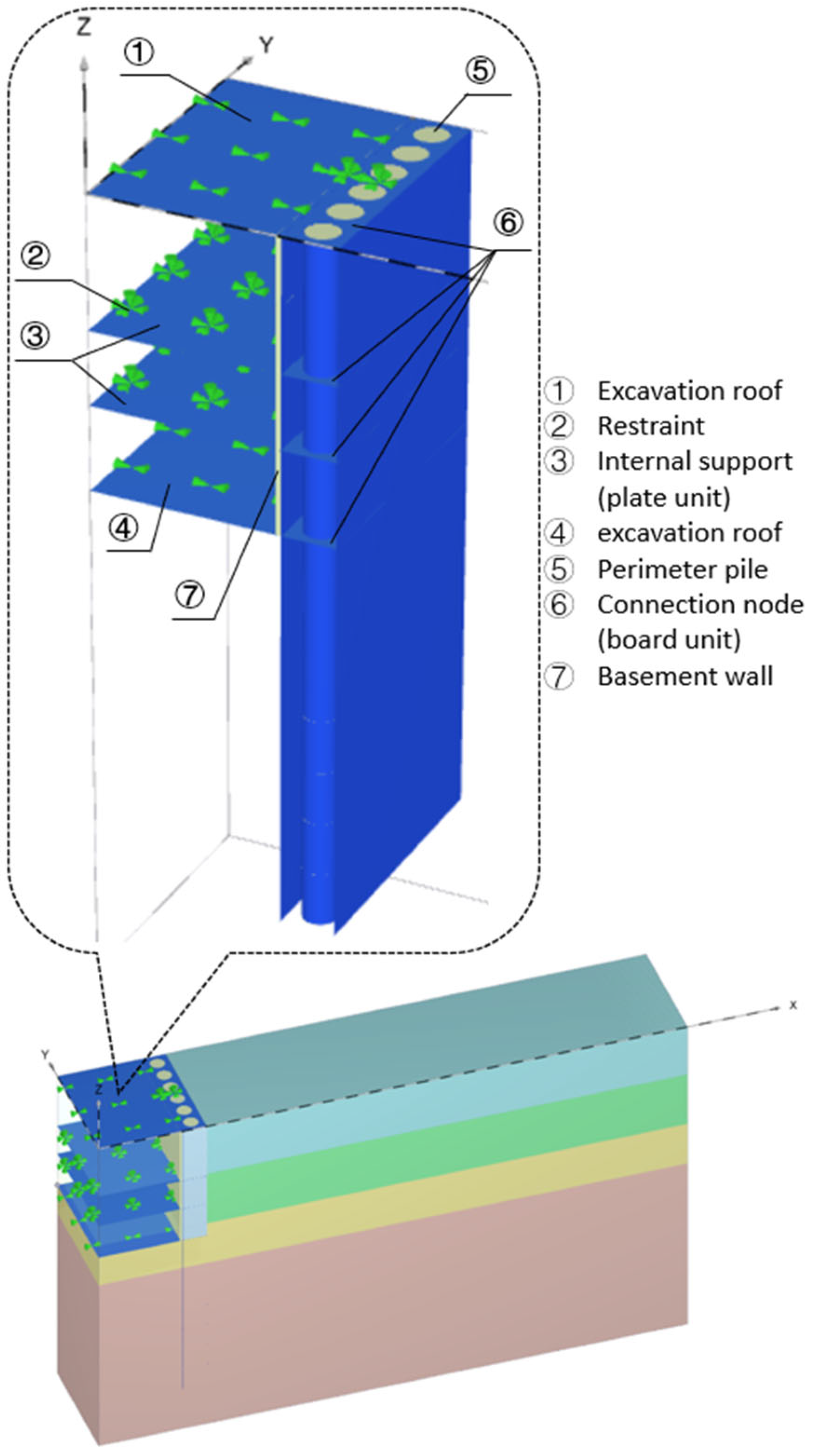
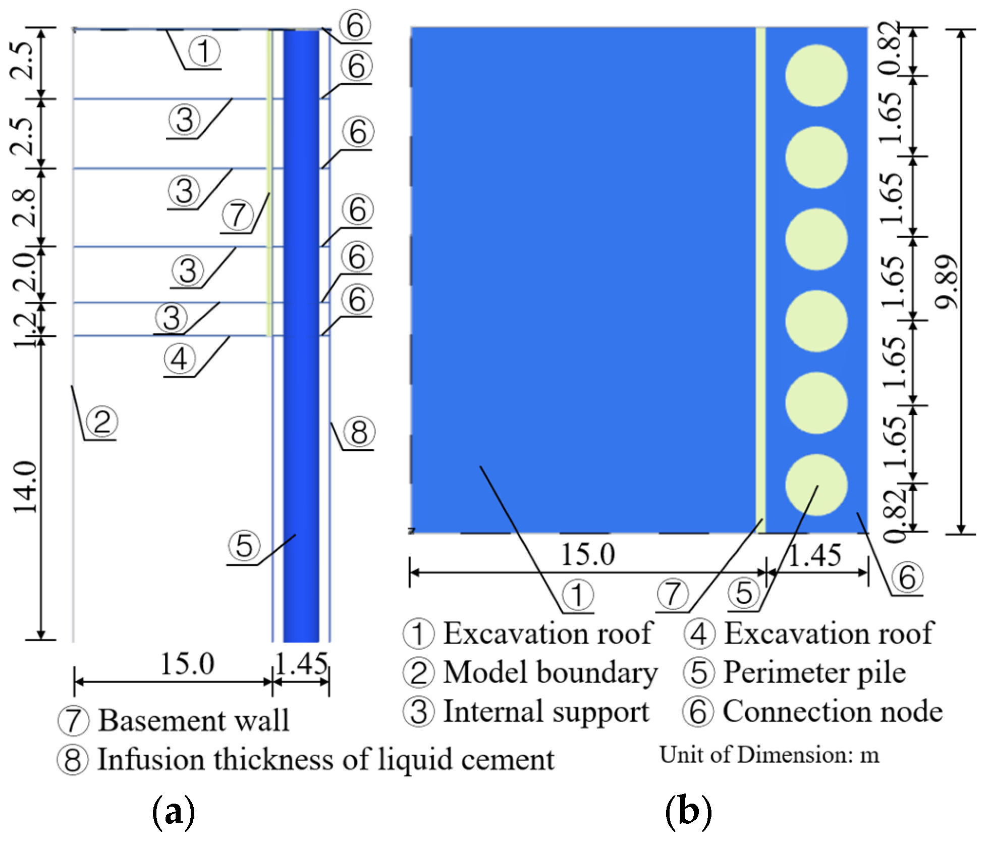
3.3.2. Model Building
- (1)
- Global model boundary settings: The global boundaries of the finite element domain are set to avoid any artificial reflections or displacement constraints that may influence the stress–deformation behavior within the excavation region. ① Bottom boundary: The entire bottom surface of the model is set as a fully fixed boundary (i.e., zero displacement in X, Y, and Z directions), simulating the reaction from the deep, undeformable subsoil. This prevents any rigid body movement of the entire model and provides realistic vertical support to the excavation structure. ② Lateral boundaries: The lateral boundaries (parallel to the X- and Y-directions) are modeled as normal fixities, where horizontal displacements perpendicular to each boundary face are restricted, while allowing in-plane deformation: specifically, the front and back boundaries (Z direction) are fixed in the Y-direction, free in X and Z, and the left and right boundaries (X direction) are fixed in the X-direction, free in Y and Z. This setting aims to mimic the semi-infinite behavior of the surrounding soil without inducing artificial lateral confinement.
- (2)
- Local structural boundary conditions: Local boundary conditions were assigned to key structural elements to reflect their functional stiffness and constraint characteristics in real construction. ① Foundation base slab ang top slab: In practical excavation engineering, both the base slab and the top slab of the basement exhibit extremely high in-plane stiffness, making their horizontal (X-direction) deformation negligible. Therefore, X-direction fixed displacement boundaries were applied to the nodes along the base and top slabs in the model to simulate a hinged constraint condition. This effectively limits lateral deformation without introducing full fixity, thus reflecting realistic rotational freedom and vertical settlement allowance. ② Retaining piles: Retaining piles were modeled with full continuity to the surrounding soil, allowing natural interaction without additional artificial constraints. Pile bottoms were embedded in the deep soil layer and tied to the fixed bottom boundary. No lateral fixity was applied along the shaft, allowing natural mobilization of soil-pile interaction along the depth. ③ Basement walls: The basement walls were connected to the foundation and perimeter piles via interface elements and connection nodes (detailed below), without additional boundary constraints, allowing them to freely interact with excavation-induced soil deformation and structural reactions.
- (3)
- Load transfer interface and connection node constraints: As discussed earlier, the connection node between the perimeter piles and the basement wall plays a critical role in force transmission. Given the modeling limitation of node-to-node anchors in Plaxis 3D (which only transmit axial force), the following composite modeling strategy was adopted. ① Connection nodes: At both the top and bottom interfaces, where piles and basement walls connect, short plate elements were inserted along the Y-direction, with a length equal to the actual connection width in the X-direction. These plate segments were embedded between the pile and wall solid elements. This allows the transfer of axial force, bending moment, and shear force across the interface. The ends of the inserted plate elements were tied via interface elements to the adjacent solid parts, ensuring continuous deformation and accurate load transfer. ② Inner supports and slabs: During staged excavation, internal horizontal supports (e.g., slabs or struts) were sequentially activated and modeled with X-direction fixed constraints at their ends to simulate their bracing function.
4. Analysis of Numerical Simulation
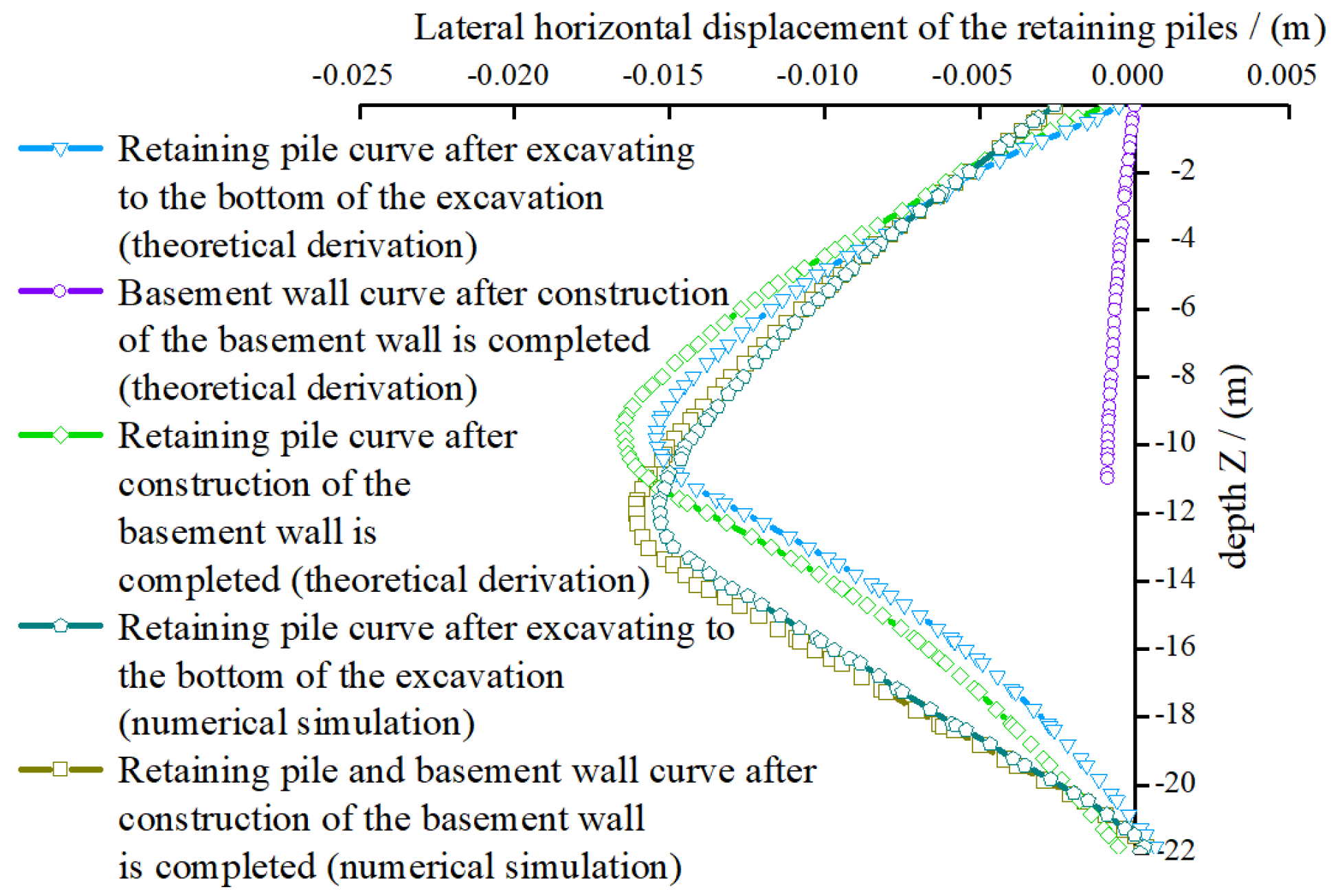
4.1. Lateral Displacement of “Pile-Wall” Structure
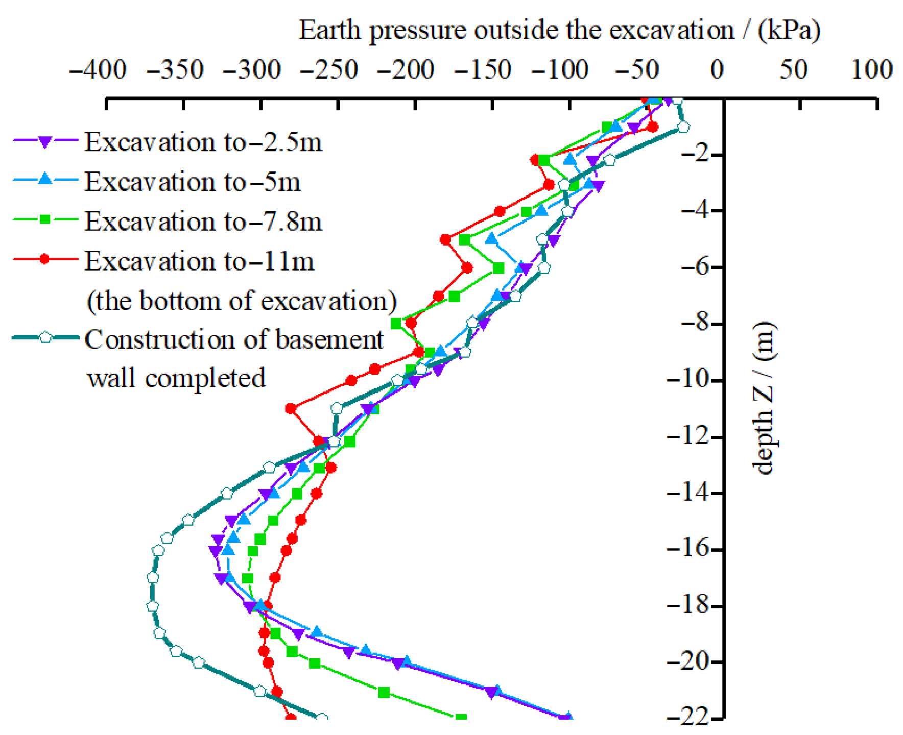
4.2. Soil Pressure Action During Construction of “Pile-Wall” Structure
- Peak earth pressure: The maximum external earth pressure is inversely related to the excavation depth. As the excavation depth increases, the peak external earth pressure decreases. At the excavation depth reaching the final excavation level, the peak earth pressure reaches its minimum value of approximately 293 kPa. The reason for this trend is that as excavation progresses, the unloading effect leads to an increasing difference in earth pressure between the inside and outside of the retaining piles. This differential pressure causes horizontal displacement of the piles, resulting in a gradual decrease in external earth pressure.
- Trend of the pressure curve: The external earth pressure exhibits a near-linear increase from the pile top (ground level, ±0 m) to 0.7–0.8 times the length of the retaining pile, where it reaches its peak value. Below this, within 0.2–0.3 times the pile length from the pile bottom (−22 m), the pressure sharply decreases. Overall, the distribution follows a nonlinear downward-convex pattern, which is consistent with the findings of Riqing Xu et al. [34] and Yingying Zhou et al. [35]. Additionally, significant pressure spikes are observed at locations where inner supports are installed. This can be attributed to the fact that inner supports restrict the lateral deformation of the retaining piles, leading to increased active earth pressure at the support locations. In contrast, below the excavation bottom, the embedded segment of the piles experiences reduced horizontal displacement, resulting in a lower active earth pressure in the embedded portion.
- Numerical values of earth pressure: The maximum external earth pressure at different excavation stages is as follows:
- (1)
- Earth pressure of 352 kPa when the retaining piles are installed;
- (2)
- Earth pressure of 326 kPa at an excavation depth of −2.5 m;
- (3)
- Earth pressure of 315 kPa at an excavation depth of −5 m;
- (4)
- Earth pressure of 289 kPa at an excavation depth of −7.8 m;
- (5)
- Earth pressure of 267 kPa at an excavation depth of −11 m.
These values indicate that the peak earth pressures comply with the allowable earth pressure limits for excavation support structures. - Earth pressure after basement wall construction: After the basement wall is constructed, the peak external earth pressure increases to approximately 379 kPa, which is higher than the peak pressure at −11 m excavation depth. The curve shape remains downward-convex, but the pressure spikes at inner support locations are slightly lower compared to the excavation process stages. This can be explained by the fact that during the construction of the basement walls, the original inner support structures are removed, eliminating the constraint effect of the inner supports on earth pressure. Additionally, during excavation, the earth pressure transitions from active to at-rest conditions. After the basement wall construction is completed, the active earth pressure fully transforms into at-rest earth pressure, which is greater than the active earth pressure. Consequently, the peak earth pressure after the basement wall construction exceeds that observed at the −11 m excavation depth.
4.3. “Pile-Wall” Structural Forces
4.3.1. Internal Forces in the Retaining Piles
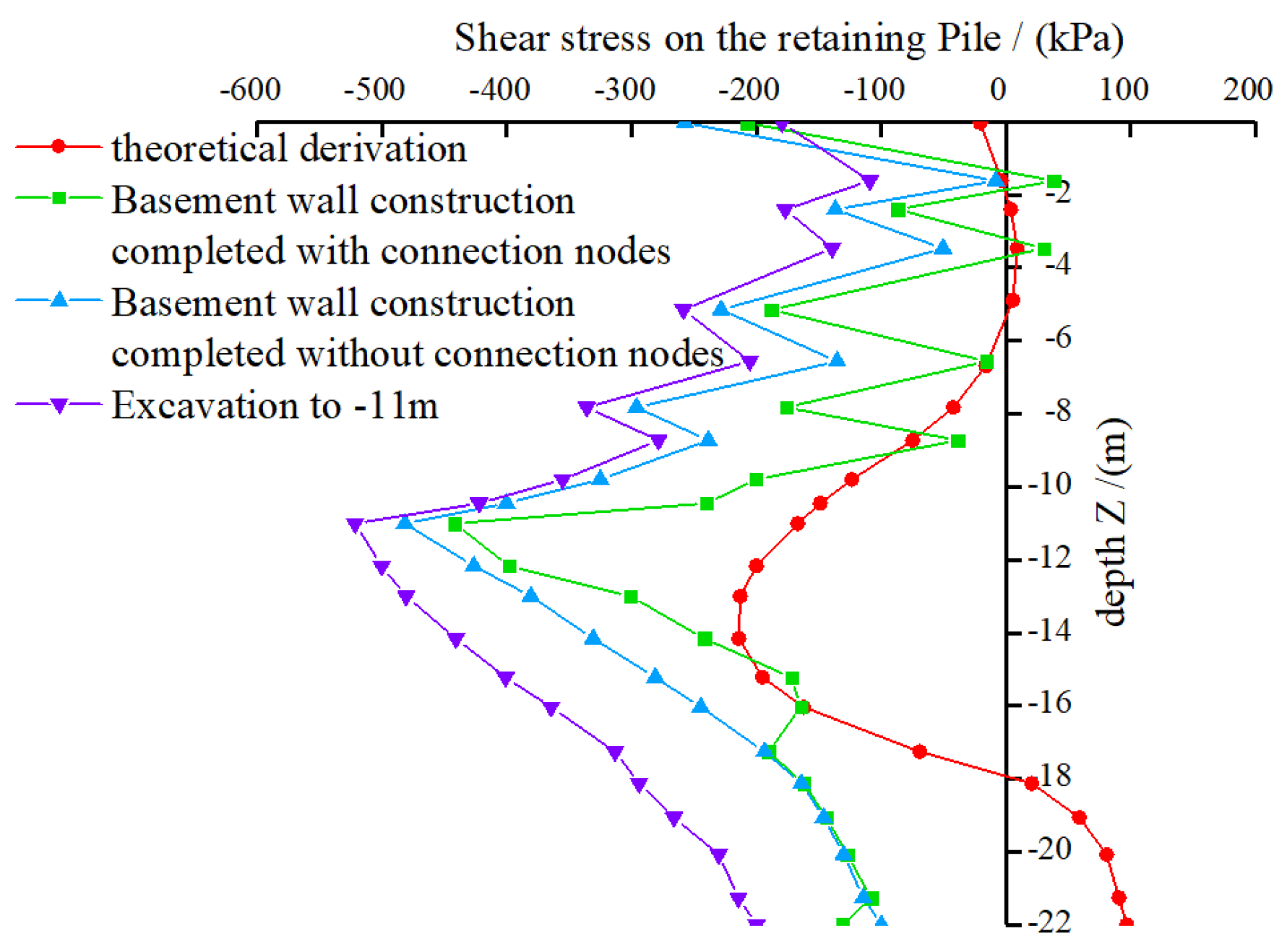
- (1)
- Peak bending moment analysis: Excluding theoretical results, the maximum bending moment in retaining piles occurs at the excavation depth of −11 m. However, after the basement wall is constructed, the bending moment in retaining piles with connection nodes is lower than in those without connection nodes. The reason is that before the basement wall is constructed, the external hydrostatic and earth pressure act entirely on the retaining piles, increasing the bending moment. Once the basement wall is completed, it shares part of the external pressure, leading to a reduction in the bending moment of the retaining piles. The connection nodes allow the external earth pressure to be distributed between the retaining piles and the basement wall according to their respective load-sharing ratios. The “pile-wall” structure formed by the connection nodes enhances structural integrity, thereby reducing the bending moment in retaining piles with connection nodes compared to those without connection nodes.
- (2)
- Curve trend analysis: The bending moment in the retaining piles shows distinct abrupt changes at the locations of inner supports, forming sharp peak points in the curve. This occurs because inner supports constrain lateral displacement, leading to sudden changes in bending moment at these locations and affecting the smoothness of the curve. Below the excavation bottom, where no inner supports exist, the bending moment curve is smoother, and its magnitude gradually decreases.
- (3)
- Numerical simulation results: The bending moment distribution above the excavation bottom exhibits a “zig–zag” pattern with multiple inflection points, where each inner support location corresponds to a turning point. Below the excavation bottom, the bending moment follows a “bulging” shape, first increasing and then decreasing. The peak bending moment appears approximately 5 m below the excavation bottom, beyond which soil disturbance diminishes, and the bending moment gradually decreases.
- (4)
- Comparison with theoretical results: Compared to the numerical simulation results, the theoretical bending moment curve is smoother. Above the excavation bottom, the bending moment values are smaller, while below the excavation bottom, the values gradually increase, reaching a peak at approximately 5 m below the excavation bottom before decreasing. This trend is consistent with the “bulging” shape observed in numerical simulations, indicating a high degree of agreement between numerical simulations and theoretical derivations.
4.3.2. Internal Force in Basement Wall
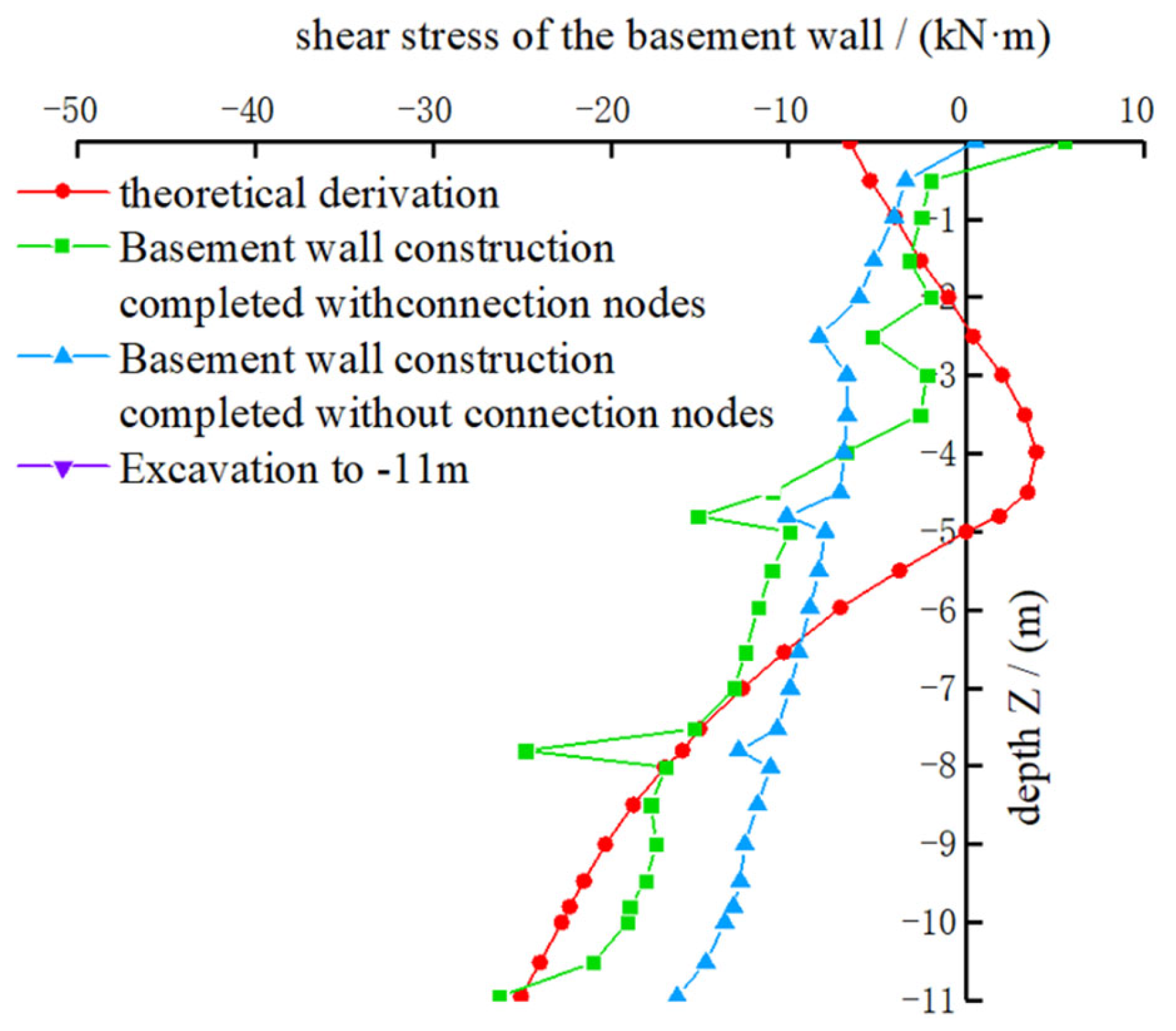
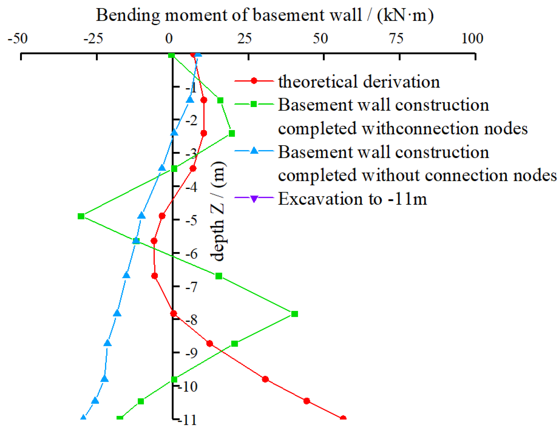
- (1)
- Peak shear stress analysis: The shear stress peak of the basement wall with connection nodes is higher than that of the wall without connection nodes. This occurs because the connection nodes enable the external earth pressure to be distributed between the retaining piles and the basement wall based on a load-sharing ratio. The “pile-wall” structure enhances the ability of the basement wall to absorb the external earth pressure transferred from the retaining piles. Consequently, the shear stress in the basement wall with connection nodes is slightly greater than that in the wall without connection nodes.
- (2)
- Curve trend analysis: The shear stress curve exhibits distinct peaks at the locations of inner supports, indicating sudden changes in shear force. This phenomenon occurs because the inner supports restrict the lateral displacement of the basement wall, causing a shear force discontinuity at these points, which affects the smoothness of the curve.
- (3)
- Numerical simulation and theoretical results: In both numerical simulation cases, the shear stress in the basement wall gradually increases with depth, reaching its peak at the excavation bottom (−11 m). However, the theoretical derivation follows a different pattern; the shear stress first decreases, reaching a local extremum at around −4 m, and then gradually increases, forming a convex-shaped distribution. Although the shear stress curve shapes differ between numerical simulations and theoretical derivations, the overall increasing trend in the numerical simulations aligns well with the theoretical results.
5. Conclusions
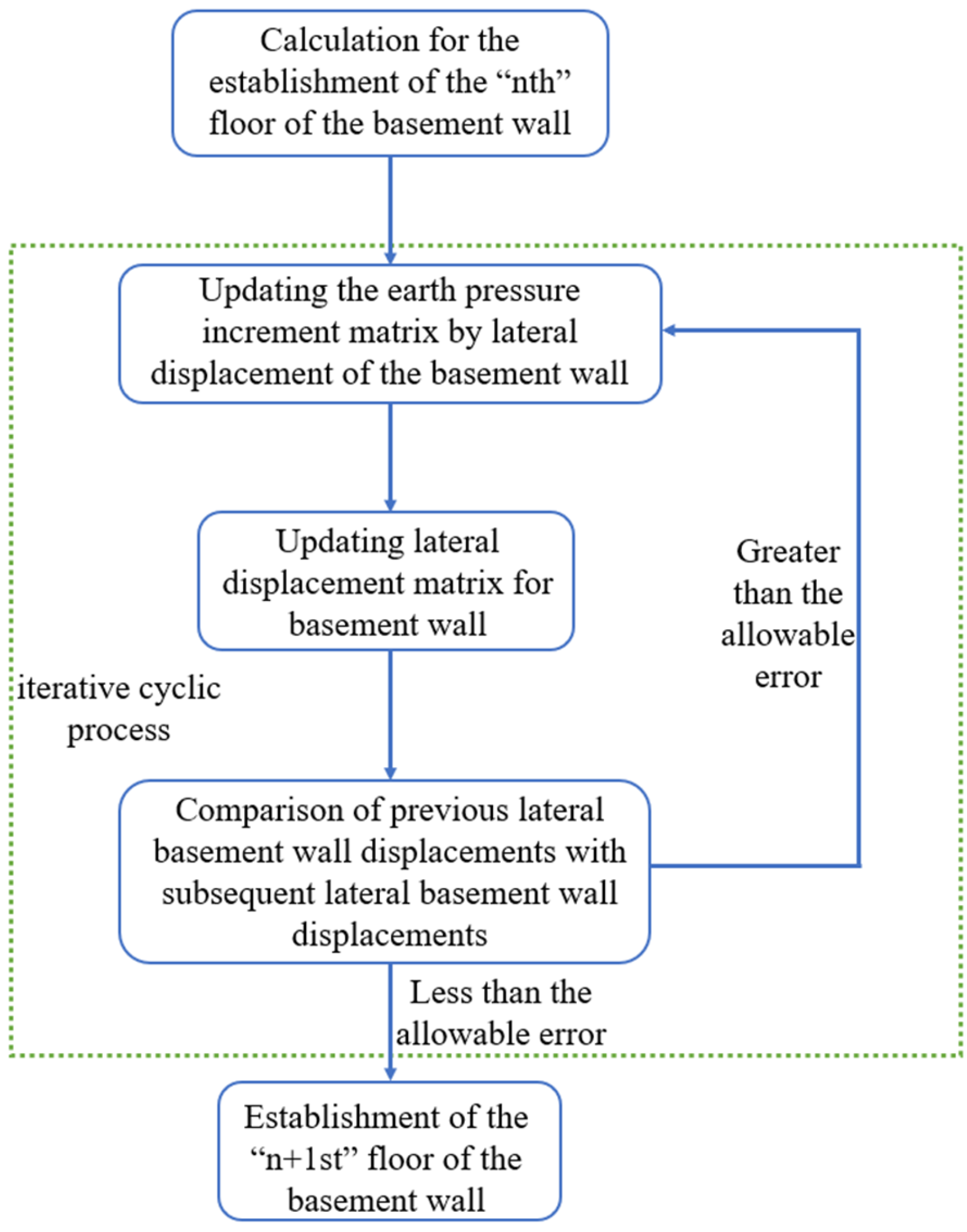
- (1)
- A simplified analytical model coupling elastic foundation beams with spring supports was developed to simulate the staged excavation and basement wall construction processes. The model accounts for the active-to-at-rest earth pressure transition and connection node effects, and its predictions of lateral displacement and internal force distributions showed good agreement with Plaxis 3D numerical simulations, validating its applicability and accuracy.
- (2)
- The horizontal displacement of the retaining piles under excavation loads exhibited a spindle-shaped distribution, with the maximum displacement occurring approximately 1 m below the excavation surface. After basement wall construction, due to the load-sharing effect of the connection nodes, the overall displacement increased slightly (by 4.2%), but remained within acceptable limits, confirming the structural stability of the integrated “pile-wall” system.
- (3)
- Earth pressure distributions during excavation followed a nonlinear concave-downward profile, with pressure peaks occurring at support locations due to lateral constraint effects. After wall construction, the earth pressure transitioned to at-rest conditions, resulting in a peak pressure of 379 kPa. These observations align with theoretical predictions and previous research and support the rationality of the staged modeling approach.
- (4)
- Theoretical and numerical results consistently indicated that the internal force peak in retaining piles occurred during the final excavation stage, while the peak in basement walls occurred post-construction. The agreement in force trends between both methods confirms that the proposed analytical model can reliably capture the force evolution and interaction mechanisms within the “pile-wall” system.
Author Contributions
Funding
Data Availability Statement
Conflicts of Interest
References
- Hua, L.; Tian, Y.; Gui, Y.; Liu, W.; Wu, W. Semi-Analytical Study of Pile–Soil Interaction on a Permeable Pipe Pile Subjected to Rheological Consolidation of Clayey Soils. Int. J. Numer. Anal. Methods Geomech. 2025, 49, 1058–1074. [Google Scholar] [CrossRef]
- Lu, B.; Sheil, B.B.; Zhao, W.; Jia, P.; Bai, Q.; Wang, W. Laboratory testing of settlement propagation induced by pipe-roof pre-support deformation in sandy soils. Tunn. Undergr. Space Technol. 2024, 146, 105645. [Google Scholar] [CrossRef]
- Wang, M.; Su, J.; Qin, H.; Shang, L.; Kang, J.; Liu, W.; Li, M.; Zhang, F.; Li, X.; Fang, Z. Research on Active Advanced Support Technology of Backfilling and Mining Face. Rock Mech. Rock Eng. 2024, 57, 7623–7642. [Google Scholar] [CrossRef]
- Hu, H.; Qi, L.; Chao, X. Physics-informed Neural Networks (PINN) for computational solid mechanics: Numerical frameworks and applications. Thin-Walled Struct. 2024, 205, 112495. [Google Scholar] [CrossRef]
- Wang, K.; Cao, J.; Ye, J.; Qiu, Z.; Wang, X. Discrete element analysis of geosynthetic-reinforced pile-supported embankments. Constr. Build. Mater. 2024, 449, 138448. [Google Scholar] [CrossRef]
- Wang, K.; Ye, J.; Wang, X.; Qiu, Z. The Soil-Arching Effect in Pile-Supported Embankments: A Review. Buildings 2024, 14, 126. [Google Scholar] [CrossRef]
- Zheng, L.; Sun, B.; Li, P.; Wang, Y. The crack calculation and experiment of the clingy “pile-wall”. Chin. J. Undergr. Space Eng. 2018, 14, 571–578+612. [Google Scholar]
- Zuo, R. Calculation of internal forces in pile-wall composite structures. Geotech. Eng. World 2003, 32–34. [Google Scholar]
- Liu, Z.; Liu, B.; Ma, X.; Yang, Z.; Xu, J. Study on the design and calculation-analysis of the excavation envelope structure of “three walls unified in-to one” of Singapore Maritime Museum. Ind. Constr. 2012, 42, 15–19. [Google Scholar] [CrossRef]
- Yi, T.; Zhang, L.; Wen, Z. Analysis for force and deformation of the pile and wall interaction based on three methods. IOP Conf. Ser. Mater. Sci. Eng. 2018, 392, 022012. [Google Scholar] [CrossRef]
- Lou, Z.; Hu, Y.; Shen, J. Design and practice of dual-purpose pile wall in a deep foundation excavation adjacent to Huangpu River. Constr. Technol. 2017, 46, 41–45. [Google Scholar]
- Hu, X. Application of the Incremental Method and Total Method in Subway Structure Calculation. Urban Mass Transit 2013, 26, 75–80+86. [Google Scholar]
- Yang, G. Practical calculation method of retaining structures for deep excavations and its application. Rock Soil Mech. 2004, 25, 1885–1896. [Google Scholar] [CrossRef]
- Liu, C.; Zheng, Z. Improved Calculation Method for Excavation Support Structures Based on p-y Curves. Rock Soil Mech. 2018, 39, 446–452. [Google Scholar] [CrossRef]
- Lu, K.; Yang, Y. Approximate Calculation Method for Active Earth Pressure Considering Displacement Effects. Rock Soil Mech. 2009, 30, 553–557. [Google Scholar] [CrossRef]
- Yue, Z.; Peng, Y.; Zhang, S. Centrifuge Model Test on Earth Pressure of Compacted Clayey Soil Retaining Wall. J. Geotech. Eng. 1992, 14, 90–96. [Google Scholar]
- Yang, B.; Hu, L. Experimental Study on the Relationship Between Lateral Earth Pressure and Horizontal Displacement of Retaining Structures. Build. Sci. 2000, 14–20. [Google Scholar] [CrossRef]
- Zhang, W.; Tian, J.; Wang, B. Analysis of the Relationship Between Earth Pressure and Soil Displacement on Excavation Support Structures. J. Hohai Univ. (Nat. Sci. Ed.) 2005, 575–579. [Google Scholar]
- Liu, J.; Hou, X. Handbook of Foundation Pit Engineering; China Building Industry Press: Beijing, China, 1997; pp. 3–55. [Google Scholar]
- Lei, G.; Su, D.; Cheng, M.; Liu, H.; Zhang, W. Incremental Method for Excavation Support Structure Calculation Based on the Reduction Process of Passive Zone Soil Spring Stiffness and Softened p–y Curves. Rock Soil Mech. 2024, 45, 797–808. [Google Scholar] [CrossRef]
- JGJ 120—2012; Technical Specification for Retaining and Protection of Building Foundation Excavations. Ministry of Housing and Urban–Rural Development of the People’s Republic of China: Beijing, China, 2012.
- Jin, Y.; Liu, D. Analytical Calculation Method for the Horizontal Stiffness Coefficient of Internal Bracing Supports in Deep Excavations. J. Geotech. Eng. 2019, 41, 1031–1039. [Google Scholar]
- Xiong, J. Simplified Calculation Method for a Type of Double-Pile Retaining Structure. Explor. Sci. Technol. 1999, 32–34. [Google Scholar]
- Hu, Y.; Wang, W.; Shen, J. Field Measurement and Analysis of the Mechanical Behavior of “Pile-Wall Integration” Structural System. Chin. J. Geotech. Eng. 2015, 37, 197–201. [Google Scholar]
- Liu, G.; Wang, W. Handbook of Foundation Pit Engineering, 2nd ed.; China Architecture & Building Press: Beijing, China, 2009. [Google Scholar]
- Wang, W.; Wang, H.; Xu, Z. Experimental Study on Parameters of Soil Hardening Model in Numerical Analysis of Foundation Pit Excavation. Rock Soil Mech. 2012, 33, 2283–2290. [Google Scholar] [CrossRef]
- Zheng, X.; Zhu, S. Study on Supporting Structure of Diaphragm Wall for Foundation Pits. J. Lanzhou Univ. Technol. 2023, 49, 137–145. [Google Scholar]
- Wang, H.; Song, E.; Xu, M. Soil Hardening Model for Underground Excavation. J. Tsinghua Univ. (Sci. Technol.) 2010, 50, 351–354. [Google Scholar] [CrossRef]
- Xie, J.; Zeng, X.; Hu, J.; Wen, Y.; Wu, C. Application of Hardening Soil Model in Deep Excavation with Pile-Anchor and Pile-Strut Composite Support. Chin. J. Geotech. Eng. 2014, 36, 56–63. [Google Scholar]
- Liu, X.; Wang, J.; Zhou, X.; Zhang, M.; Wang, L.; Xu, B.; Lou, X. Response of Long–Short Supporting Piles due to Deep Excavation in Soil–Rock Combined Strata. Int. J. Geomech. 2024, 24, 04023276. [Google Scholar] [CrossRef]
- Wu, C.; Yu, J.; Cao, X.; Shen, W. Study on Design Method of pile-wall Combination Structure in a Deep Foundation Pit Considering Deformation Induced by Excavation. Front. Earth Sci. 2022, 10, 837950. [Google Scholar] [CrossRef]
- Qaftan, O.S.; Toma-Sabbagh, T.; Weekes, L.; Augusthus-Nelson, L. Validation of a Finite Element Modelling Approach on Soil–Foundation–Structure Interaction of a Multi-Storey Wall–Frame Structure under Dynamic Loadings. Soil Dyn. Earthq. Eng. 2020, 131, 106041. [Google Scholar] [CrossRef]
- Chen, Y. Application of a new retaining structure in deep underground projects adjacent to sensitive environment. Chin. J. Geotech. Eng. 2015, 37, 70–73. [Google Scholar] [CrossRef]
- Xu, R. Earth Pressure Calculation Method Considering Displacement and Time. J. Zhejiang Univ. (Eng. Sci.) 2000, 34, 370–375. [Google Scholar]
- Zhou, Y.; Ren, M. Experimental Study on Active Earth Pressure of Rigid Retaining Walls. Chin. J. Geotech. Eng. 1990, 12, 19–26. [Google Scholar]


| Materials | H/m | γunsat/(kN·m−3) | E′/MPa | C′/kPa | φ /(°) |
|---|---|---|---|---|---|
| Filling | 4.8 | 19.0 | 8.9 | 36 | 13.4 |
| Silty clay | 5.0 | 19.3 | 8.4 | 40 | 13.5 |
| Clay | 4.0 | 19.3 | 12.1 | 54 | 14.7 |
| Red clay | 11.2 | 18.3 | 19.9 | 84 | 16.4 |
| ① | ② | ③ | ④ | |
|---|---|---|---|---|
| Materials | Fillings | Silty Clay | Clay | Red Clay |
| Thickness/m | 4.8 | 5.0 | 4.0 | 11.2 |
| γunsat/kN·m−3 | 19.0 | 19.3 | 19.3 | 18.3 |
| Cohesion (C)/kPa | 36 | 40 | 54 | 84 |
| The angle of internal friction (φ)/° | 13.4 | 13.5 | 14.7 | 16.4 |
| Es1−2/kPa | 8.9 | 8.4 | 12.1 | 19.9 |
| ψ | 0 | 0 | 0 | 0 |
| Eoedref/kPa | 8.9 | 8.4 | 12.1 | 19.9 |
| E50ref/kPa | 8.9 | 8.4 | 12.1 | 19.9 |
| Eurref/kPa | 35.6 | 33.6 | 48.4 | 79.6 |
| m | 0.8 | 0.8 | 0.8 | 0.8 |
| Rf | 0.9 | 0.9 | 0.9 | 0.9 |
| Rinter | 0.65 | 0.65 | 0.65 | 0.65 |
| ν | 0.2 | 0.2 | 0.2 | 0.2 |
| Drainage state | drainage | drainage | drainage | drainage |
| Materials | Drainage Type | γunsat/kN·m−3 | Elastic Modulus (E)/kPa | ν |
|---|---|---|---|---|
| Concrete | non-porous | 25 | 31.00 × 10⁶ | 0.1 |
| liquid cement | non-porous | 12 | 4.0 × 10³ | 0.1 |
| Member | Analog Unit | γunsat | H | E |
|---|---|---|---|---|
| Excavation roof | Plate unit | 25 | 0.4 | 4 × 10⁸ |
| Excavation floor | Plate unit | 25 | 0.4 | 4 × 10⁸ |
| Internal support | Plate unit | 25 | 0.2 | 2.1 × 10⁸ |
| Connection node | Plate unit | 25 | 0.2 | 2.1 × 10⁸ |
| Soil | Elevation (±0 at Ground Level) | γunsat/(kN·m−3) | |
|---|---|---|---|
| 1 | Layer 1 connection node | ±0 | 25.0 |
| 2 | Layer 2 connection node | −2.5 | 25.0 |
| 3 | Layer 3 connection node | −5.0 | 25.0 |
| 4 | Layer 4 connection node | −7.8 | 25.0 |
| 5 | Layer 5 connection node | −9.8 | 25.0 |
| 6 | Layer 6 connection node | −11 | 25.0 |
Disclaimer/Publisher’s Note: The statements, opinions and data contained in all publications are solely those of the individual author(s) and contributor(s) and not of MDPI and/or the editor(s). MDPI and/or the editor(s) disclaim responsibility for any injury to people or property resulting from any ideas, methods, instructions or products referred to in the content. |
© 2025 by the authors. Licensee MDPI, Basel, Switzerland. This article is an open access article distributed under the terms and conditions of the Creative Commons Attribution (CC BY) license (https://creativecommons.org/licenses/by/4.0/).
Share and Cite
Wei, H.; Wang, P.; Zheng, X. Analytical and Numerical Investigation of Internal Force Distribution in “Pile-Wall” Structures Based on Finite Difference Method. Buildings 2025, 15, 1455. https://doi.org/10.3390/buildings15091455
Wei H, Wang P, Zheng X. Analytical and Numerical Investigation of Internal Force Distribution in “Pile-Wall” Structures Based on Finite Difference Method. Buildings. 2025; 15(9):1455. https://doi.org/10.3390/buildings15091455
Chicago/Turabian StyleWei, Huanwei, Pengyue Wang, and Xiao Zheng. 2025. "Analytical and Numerical Investigation of Internal Force Distribution in “Pile-Wall” Structures Based on Finite Difference Method" Buildings 15, no. 9: 1455. https://doi.org/10.3390/buildings15091455
APA StyleWei, H., Wang, P., & Zheng, X. (2025). Analytical and Numerical Investigation of Internal Force Distribution in “Pile-Wall” Structures Based on Finite Difference Method. Buildings, 15(9), 1455. https://doi.org/10.3390/buildings15091455