Abstract
By integrating a very short shear link–shear slotted bolted connection (VSSL-SSBC) and two self-centering SMA braces (SCBs), a novel self-centering shear link (SC-SL) was developed for installation between a steel brace and steel beam in an eccentrically braced frame (EBF). The SC-SL can enhance the seismic performance and seismic resilience capacity of the EBF by achieving a high bearing capacity and low residual deformation. The mechanical properties of the VSSL-SSBC and SC-SL were designed and analyzed using both experimental and numerical methods. Subsequently, the seismic performances of EBFs equipped with VSSL-SSBC and SC-SL were analyzed under different earthquakes. Validated numerical methods were employed to investigate the deformation modes, stress nephograms, and hysteresis curves of the EBFs. The deformation mode and hysteresis curve of the VSSL-SSBC exhibit an initial frictional slip of the SSBC, followed by the load-bearing response of the VSSL. The skeleton curve of the VSSL-SSBC consists of elastic, slip, elastoplastic, and plastic stages, and the deformation and damage are significantly reduced at the same displacement. In the SC-SL, the SCB undergoes substantial deformation when the SMA is in tension, effectively minimizing residual deformation. Under frequent earthquakes, the stress and displacement of all components in both the EBF-VSSL-SSBC and EBF-SC-SL are essentially equivalent, and the VSSL-SSBC remains elastic, without significant yielding deformation. Under rare earthquakes, incorporating SCB in EBF-SC-SL significantly enhances the ultimate load capacity by 19.66% and reduces the residual deformation by 27.90%. This improvement greatly contributes to the seismic resilience of the EBF.
1. Introduction
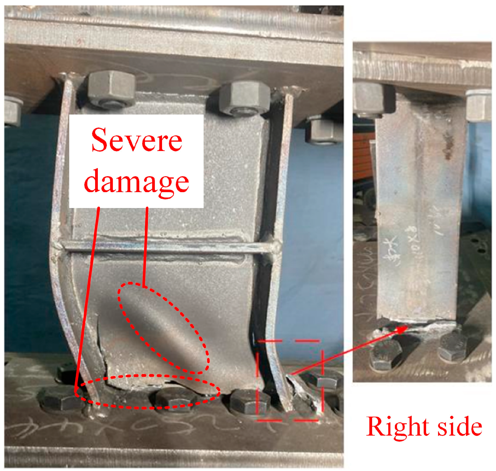
Eccentrically braced frames (EBFs) are composed of steel columns, steel frames, steel braces, and links, representing a seismic design approach that effectively combines the high energy dissipation, ductility, and damage control capabilities [1,2,3]. The link, commonly known as the fuse, plays a crucial role in dissipating seismic energy and protecting the primary load-carrying elements of EBFs [4,5]. Links are classified based on their length ratios into three categories: shear link, flexural-shear link, and flexural link [6]. Very short shear links (VSSLs), characterized by a length ratio less than 1.0, exhibit obviously higher overstrength factors and inelastic rotation capacities, with values of 1.90 and 0.15 rad, respectively, both exceeding the standard code prescribed in building codes of 1.50 and 0.08 rad [7,8,9]. The ultimate shear force, deformation capacity, and lateral stiffness of VSSLs are superior to those of the other three types, making a substantial contribution to the overall seismic performance of EBFs [10]. In recent years, there has been growing interest in seismic-resilient structures within the field of civil engineering [11]. On 6 February 2023, at 04:17 local time (01:17 UTC), a magnitude (Mw) 7.7 earthquake struck the Pazarcık segment of the East Anatolian Fault (EAF) zone. This earthquake caused damage to residential houses, bridges, hospitals, and historical buildings, posing a challenge to the seismic performance of current structures [12,13,14]. However, the links in EBFs are susceptible to severe damage and residual deformation (Figure 1), leading to increased repair costs and the need for advanced rehabilitation techniques [15,16]. Therefore, enhancing the energy-dissipating and self-centering capabilities of VSSLs in EBFs is crucial to achieving higher seismic design standards.

Figure 1.
Damage and residual deformation of shear link in EBF.
Slotted bolted connections (SBCs) utilize the friction-slip mechanism generated by high-strength bolts slipping within the slot holes to achieve simultaneous energy dissipation and ductility improvement. This connection technology has found successful applications in steel frame components including beam–column joints, frame beams, and energy dissipation braces, substantially boosting the seismic performance of structures [17,18]. Research indicates that SBCs demonstrate three key advantages: stable hysteresis response, enhanced ductility, and cost-effective post-earthquake repair [19,20,21]. Liu et al. [19] proposed a prefabricated steel structural system with truss beams and bolted joints, and enlarged bolt holes were adopted in the joints for easier assembly and better energy dissipation. Zhang et al. [20] applied SBCs to replaceable steel beams in the proposed hybrid frame structure with energy dissipation frames (HF-EDFs) to improve seismic performance and recoverability. Zhai et al. [21] proposed a new type of bolted connection with a dual-slot hole and two kinds of connection-strengthening methods, including diagonal brace strengthening and flange strengthening. By integrating a VSSL with a shear slotted bolted connection (SSBC), a very short shear link with shear slotted bolted connections (VSSL-SSBCs) can be developed to further enhance the ductility and energy dissipation while minimizing damage [22]. However, VSSL-SSBCs may still experience high residual deformation, which can reduce the overall seismic capacity of the EBFs.
Shape memory alloy (SMA) is a category of intelligent material distinguished by its inherent material memory characteristics. These alloys possess distinctive shape recovery characteristics following repeated loading–unloading cycles, providing both energy-dissipating and self-centering capabilities. Experimental investigations have verified strain restoration levels reaching up to 8% under controlled deformation conditions [23]. Feng et al. [24] proposed an asymmetric self-centering steel connection equipped with SMA damper devices, which can experience a typical flag-shaped curve with high energy dissipation and self-centering capabilities. Qiu et al. [25] developed a NiTi-SMA BRB in knee braced frames, which can successfully eliminate residual drift ratios and has higher seismic resilience for the protected frames. Sun et al. [26] proposed an innovative sliding self-centering brace to reduce or eliminate residual deformation after strong earthquakes. Li et al. [27] conducted a study on a new self-centering coupling beam (SCCB) incorporating self-centering friction dampers (SCFDs) to improve the seismic resilience of the coupled wall structure. Additionally, Jia et al. [28] developed an innovative SCB with superior self-centering capacity and energy-dissipating capacity, and the hysteresis curve of the SCB was idealized as a flag shape with low residual deformation.
Existing research has indicated that enhancing the self-centering capacity of steel frames can effectively reduce residual deformation, which facilitates post-earthquake repair. Rahgozar et al. [29] studied the sensitivity analysis of controlled-rocking steel cores (CRSCs) under seismic loadings, and the results showed that CRSCs effectively prevent earthquake-induced residual damage but may suffer large lateral displacements. Chen et al. [30] investigated a novel K-type superelastic SMA self-centering eccentrically braced frame, and the simulation models of the SMA-based SC-EBF and a corresponding equal-stiffness traditional EBF counterpart were established. The results showed a much better resilience and represent a promising attractive alternative for future applications. Xiong et al. [31] proposed a novel self-centering frame with Y-eccentrically braced structures (SC-YEBFs) to solve the problem that the storey drift of the structure may exceed the specified limit in standards when self-centering beam–column joints are applied in high-rise and larger span buildings. The test and finite element results indicated that shear link has increased the lateral stiffness and energy dissipation capacity of the structure and maintained a good self-centering performance and replaceability.
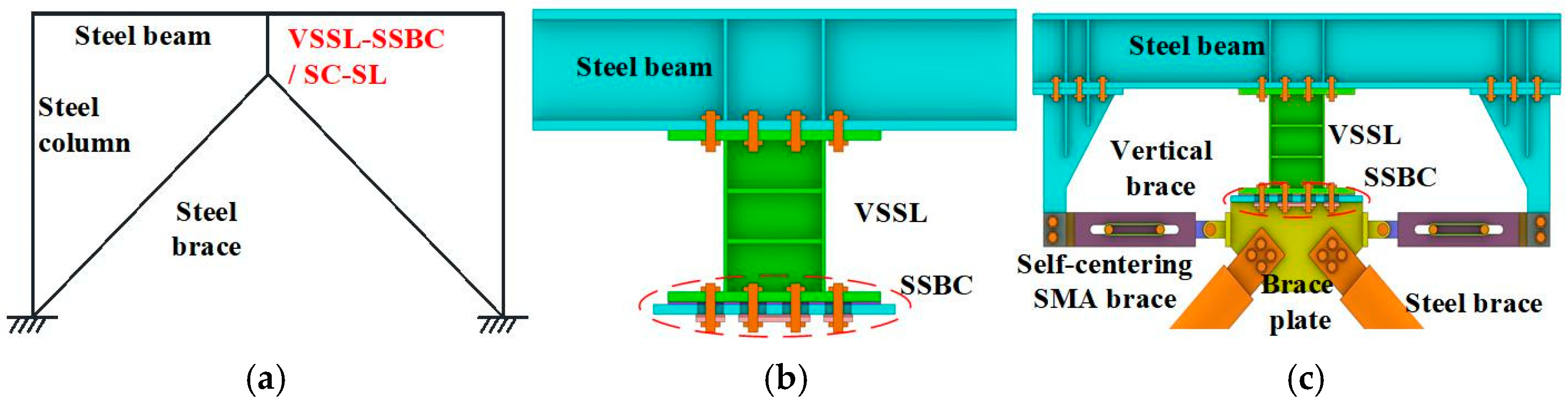
In this paper, a novel SC-SL is proposed to achieve high bearing stiffness and ductility while minimizing residual deformation, as shown the Figure 2. The SC-SL includes a VSSL, two SCBs, and two vertical braces. Compared with the self-centering devices in existing studies, SC-SL exhibits both high energy dissipation and self-centering capacities, meeting the high requirements of seismic design [29,30,31]. The SC-SL can not only be applied to new buildings to improve the bearing capacity and energy dissipation capacity of the structure but can also be applied to existing structures through simple bolt connections to enhance the seismic performance and self-centering capacity of the structure. Cyclic loading tests were conducted on a VSSL-SSBC and an SC-SL specimen. The failure modes, hysteresis curves and skeleton curves were analyzed and their seismic performances compared. Furthermore, to access the structural response under frequent and rare earthquakes, two EBFs incorporating VSSL-SSBC and SC-SL were analyzed. Validated numerical methods were employed to investigate the deformation modes, stress nephogram, and hysteresis performance. The findings provide valuable insights for seismic design, offering reliable references to enhance the seismic resilience capacity of EBFs.
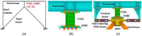
Figure 2.
A novel eccentrically braced frame applied with SC-SL: (a) EBF; (b) VSSL-SSBC; (c) SC-SL.
2. Basic Performance
2.1. Basic Component
As shown in Figure 3, the SC-SL primarily consists of the VSSL-SSBC and two SCBs. The VSSL-SSBC is composed of a very short shear link (VSSL) and shear slotted bolted connection (SSBC), with the VSSL connected at both ends to the SSBC and the frame beam. The SSBC mainly consists of the VSSL, endplates I and II, base plates, and a metallic and rubber shim. The rubber shim is placed between endplate II (at the brace end) and the base plate, while the metallic shim is positioned between endplate I and endplate II. The self-centering SMA brace includes two slip plates, two slip bolts, a fixed plate, fixed bolt I, two fixed bolts II, and SMA wires. The two slip plates and the fixed plate each have two identically sized slot holes at corresponding positions on both sides. Initially, the two slip bolts are positioned at the ends of the left and right slot holes, near the opposite slot hole. Additionally, the vertical connection brace is secured to the beam by fixed bolt I, while the other end is attached to the one end plate of the SCB with two fixed bolts II. Meanwhile, the other end plate of the SCB is secured to the brace plate, thus forming the SC-SL.
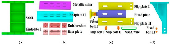
Figure 3.
Basic components of an SC-SL: (a) VSSL; (b) SSBC; (c) SCB; (d) Vertical brace.
2.2. Working Mechanism
Figure 4 is the working mechanism of the SC-SL during cyclic loading. The SSBC and VSSL provide the initial and subsequent energy dissipation capacity of the structure, respectively, while the SCB provides the self-centering capacity during the entire process. Under cyclic loading, the frame beam in the SC-SL drives the VSSL-SSBC and the SCB to work in unison. Within the VSSL-SSBC, the SSBC first experiences frictional slip, while the VSSL remains elastic without undergoing shear yielding. Once the high-strength bolt reaches to the end of the slot hole, the VSSL begins to yield in shear, absorbing the load and deforming until failure. Throughout the entire loading process, one sliding bolt in the self-centering SMA brace remains fixed while the other moves, ensuring that the SMA wires remain continuously in tension. As a result, SCB I and SCB II effectively provide both energy-dissipating and self-centering capabilities during positive and negative moving. This synergistic mechanism enhances the energy-dissipating efficiency and minimizes residual deformation in the SC-SL.
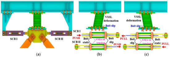
Figure 4.
Working principle for EBF with SC-SL during cyclic loading: (a) SC-SL; (b) Positive moving; (c) Negative moving.
2.3. Design Method
At the ultimate limit state, both the VSSL-SSBC and the SCB within the SC-SL may experience failure, manifested as follows: (1) When the deformation of the SCB exceeds the deformation capacity of the SMA, while the VSSL-SSBC has not yet reached its limit state, failure of the SC-SL primarily occurs in the SCB, leading to the fracture of the SMA. (2) The SMA in the SCB is expected to remain in a superelastic state and continue to provide both energy-dissipating and self-centering capabilities; however, failure may occur in the VSSL once the SMA reaches its ultimate displacement, marking the ultimate limit state of the SC-SL. To ensure that the SC-SL achieves the expected energy-dissipating and self-centering performance, the design must adhere to the following requirements.
(1) VSSL-SSBC
The initial shear slip load, Fslip, of the SSBC must be lower than the yield shear force, Vy, of the VSSL. At the ultimate limit state, the load-bearing capacity, Fu, of the SSBC must be higher than the ultimate shear force, Vu, of the VSSL. These relationships can be expressed as follows [6,10]:
where ns, nb, P, μ, d, and fvb are the number of sliding contact planes, number of sliding bolts, pretension force of the bolt, coefficient of friction, diameter of the slip bolt, and the yield stress of the slip bolt in the SSBC, respectively. fyw, fuw, hw, tw, bf, tf, ts, and e are the web yield shear stress, web ultimate shear stress, web clear height, web thickness, flange width, flange thickness, stiffener thickness, and length of the VSSL-SSBC, respectively.
(2) SCB
The load-bearing capacity, FSCB, of the SCB primarily consists of the load-bearing capacity of the SMA, FSMA, and the force provided by the slotted bolt connection, Ff, which can be expressed as follows:
where As and σSMA are the area and stress of the SMA wires, which can be calculated by the Graesser model [23], and ns and nb are the number of sliding contact planes and sliding bolts, which are equal to 6 and 2, respectively. PS is the pretension force of the bolt, and μ is the rubber shim friction coefficient (0.075) [22].
(3) Steel brace
The seismic design code specifies the detailed design methods for eccentrically braced structural members. After the plastic failure occurs in the shear link, the steel brace is expected to remain in an elastic state at all times. Its axial bearing capacity can be calculated and designed according to the following equations:
where Ω is the overstrength factor of the shear links. Nbr and Nbr,com are the calculated and designed values of the steel brace axial force, and φ and Abr are the stability coefficient and cross-sectional area of the steel brace. fbr is the design value of the tensile strength of the steel brace.
(4) Frame beam and column
The seismic design code also provides detailed design methods for frame beams. The design values of internal forces can be expressed as follows:
where Mb and Mb,com are the calculated and designed values of the bending moment of the frame beam. Nb, Anb, and Wnbx are the axial force, net sectional moment of resistance, and net sectional area of the frame beam, respectively. γx and fb are the plastic section development coefficient and yield strength of the frame beam, respectively.
(5) Column
The seismic design code has provided detailed design methods for columns in EBFs. The design values of the internal forces can be expressed as follows:
where Mc and Mc,com are the calculated and designed values of the bending moment of the column, and Nc and Nc,com are the calculated and designed values of the axial force of the column. Anc, fc, and Wnc are the axial force, net sectional moment of resistance, and net sectional area of the column, respectively. fc and φ are the design value of the tensile strength and the stability coefficient of the column.
3. Experimental Study of VSSL-SSBC and SC-SL
3.1. Test Plan
3.1.1. Specimen Design
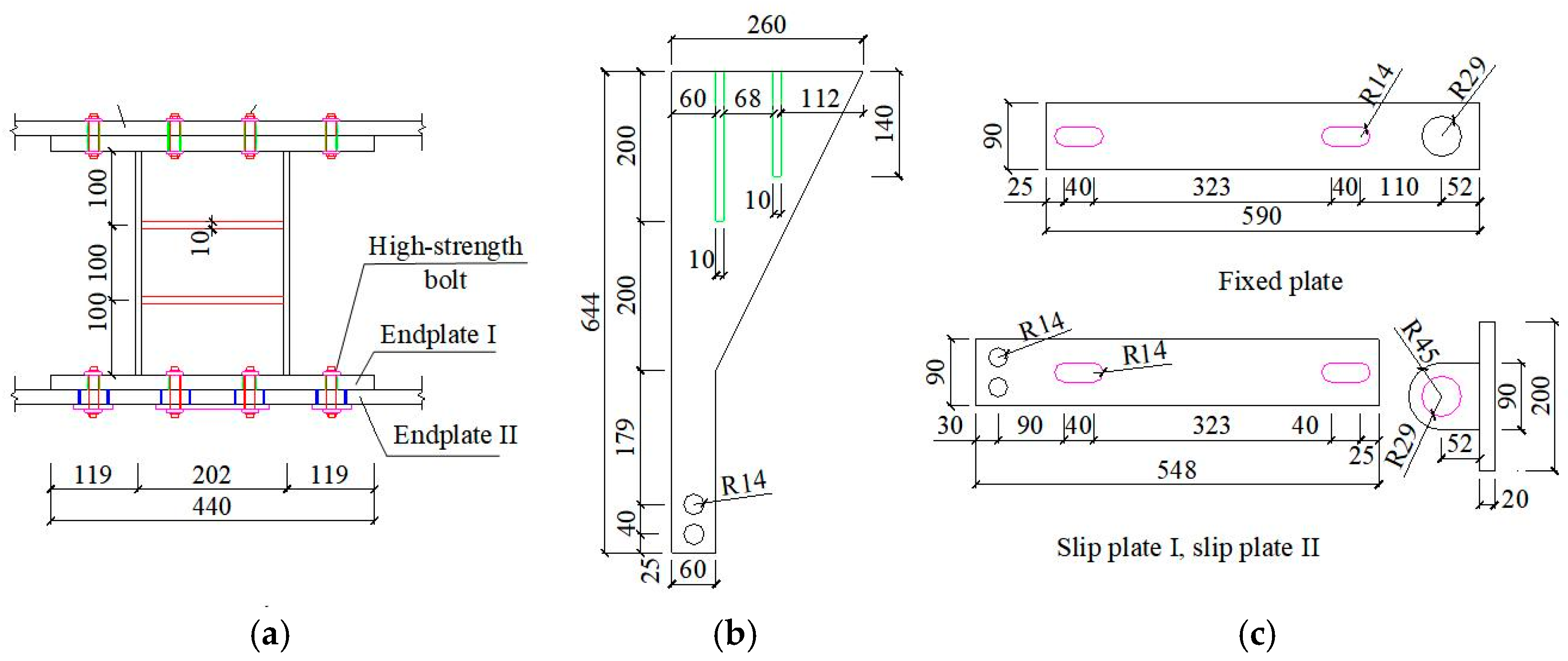
To explore the seismic performance and seismic resilience of the eccentrically braced frame (EBF) with self-centering shear link (SC-SL), a specimen of a very short shear link with shear slotted bolted connection (VSSL-SSBC-1) and a self-centering shear link specimen (SC-SL-1) are designed according to Equations (1)–(3). The mechanical properties and self-centering capacity of SC-SL can be effectively explored by comparing the hysteretic curves and failure modes of the VSSL-SSBC-1 and SC-SL-1 specimens. The specific dimensions of each specimen are presented in Figure 5, and the main parameters of each specimen are shown in Table 1. For the VSSL-SSBC-1 specimen, the cross-sectional dimensions of the VSSL are H210 × 110 × 6 × 8 mm, with a length of 300 mm. Stiffeners are symmetrically arranged on both sides, spaced at intervals of 100 mm, with a thickness of 10 mm. Endplate I has dimensions of 440 × 250 × 20 mm, while endplate II features eight slot holes measuring 34 mm in length and is connected using M22 high-strength bolts. A copper shim is placed between endplate I and endplate II to enhance the connection quality. For the SCB in the SC-SL-1 specimen, the fixed plate measures 590 × 90 × 10 mm, and both slip plates have dimensions of 548 × 90 × 10 mm. The SMA wires used in the SC-SL-1 specimen are arranged in 30 circles with an area of 94.20 mm2. The bolt circular hole has a radius of 14 mm, and the slot hole measures 40 mm in length. The vertical brace in the SC-SL-1 specimen has a height, width, and thickness of 644 mm, 260 mm, and 10 mm, respectively. The lower end of the vertical brace contains two circular holes with a radius of 14 mm, and the upper end is reinforced with two stiffeners, symmetrically arranged on both sides. Note that all the units associated with the multiplication signs in this paper are in millimeters.
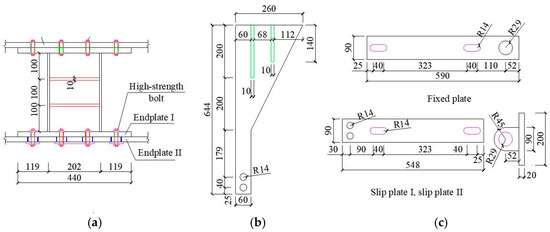
Figure 5.
Dimensions of the VSSL-SSBC and SC-SL specimens: (a) VSSL-SSBC; (b) Vertical brace; (c) Self-centering SMA brace.

Table 1.
Primary parameters for experimental specimens.
3.1.2. Material Properties
The structural elements in the VSSL-SSBC-1 and SC-SL-1 specimens were fabricated using Q355B grade steel plates with varying thicknesses ranging from 6 to 15 mm. Tensile tests were conducted on standardized test coupons to determine the material properties of the Q355B steel across different plate thicknesses [32], with the detailed results presented in Table 2. As for the 10.9 grade high-strength bolts, the yield and ultimate strength are 940 MPa and 1040 MPa, respectively.
Table 2.
Mechanical parameters of steel plates.
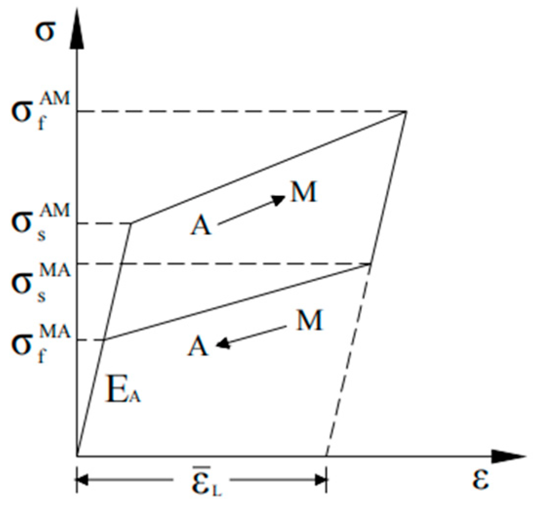
All SMA wires employed in the experimental program maintained a consistent cross-sectional dimension of 1.0 mm in diameter. Tensile tests were conducted on a 375 mm long SMA wire with the same diameter to determine and validate the mechanical characteristics [24]. The key mechanical parameters are as follows, as illustrated in Figure 5: the starting stresses (σsAM) and ending stresses (σfAM) for the austenite-to-martensite phase transformation are 550 MPa and 625 MPa, respectively, while the starting stresses (σsMA) and ending stresses (σfMA) for the martensite-to-austenite phase transformation are 265 MPa and 175 MPa, respectively. The maximum phase transformation strain and the initial elastic modulus (EA) are 0.06 and 59,531 MPa, respectively. The SMA numerical model can be utilized to simulate the hysteresis curve of the SMA wire through the UMAT program in ABAQUS software 2021. Figure 6 presents the simplified relationship curve of the SMA.
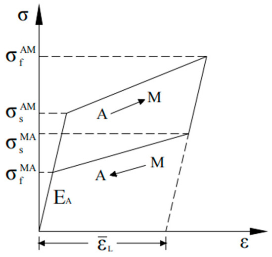
Figure 6.
Constitutive model of SMA.
3.1.3. Test Setup and Loading Protocol
(1) Test setup
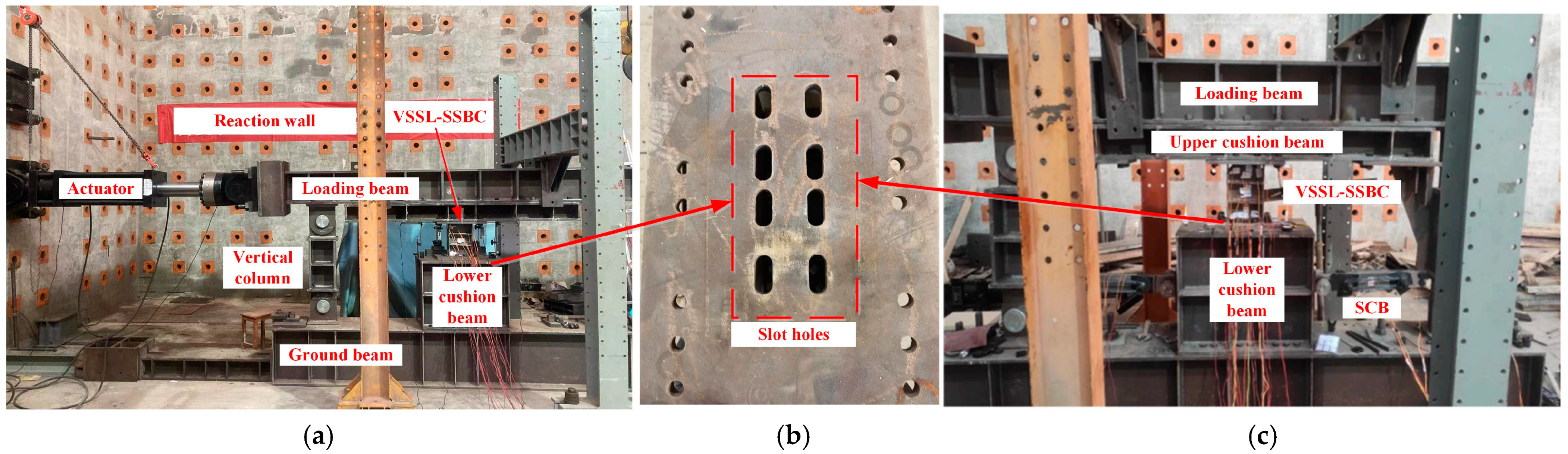
The experimental study of the VSSL-SSBC-1 and SC-SL-1 specimens was conducted in the structural engineering lab of Nanchang University (Figure 7). The test device primarily consists of VSSL-SSBC-1/SC-SL-1, a loading beam, upper and lower cushion beams, two vertical columns, and a ground beam. For the VSSL-SSBC-1 specimen, the upper end is secured to the upper cushion beam via eight high-strength bolts, which are also secured to the loading beam. The lower end is fastened to the lower cushion beam using eight high-strength bolts, with the lower cushion beam containing eight slot holes. In the SC-SL-1 specimen, the test setup of VSSL-SSBC is identical to that in VSSL-SSBC-1. The SCB is connected to the vertical brace using two high-strength bolts, while the other end is linked to the lower cushion beam via a pin connection. Additionally, the upper end of the vertical brace is secured to the upper cushion beam using six high-strength bolts, forming the corresponding loading setup.

Figure 7.
Test device of VSSL-SSBC-1 and SC-SL-1 specimens: (a) VSSL-SSBC-1; (b) Slot holes; (c) SC-SL-1.
(2) Loading protocol
The VSSL-SSBC-1 and SC-SL-1 specimens were subjected to displacement-controlled loading. At the beginning, displacements of ±6 mm, ±10 mm, and ±16 mm were applied. As the high-strength bolts slid to the ends of the slot holes, the displacement increments for each loading step were set as follows: ±0.5S1 ± 0.01e, ±0.5S1 ± 0.03e, ±0.5S1 ± 0.05e, ±0.5S1 ± 0.07e, and so on [22], until the specimens failed and loading was stopped. In this context, S1 represents the length of the slot hole on the top plate of the lower cushion beam in the VSSL-SSBC, while e denotes the length of the VSSL. In the displacement loading scheme, the symbols “+” and “−” indicate the maximum positive and negative displacement values within a single cyclic loading, respectively.
3.1.4. Measurement Scheme
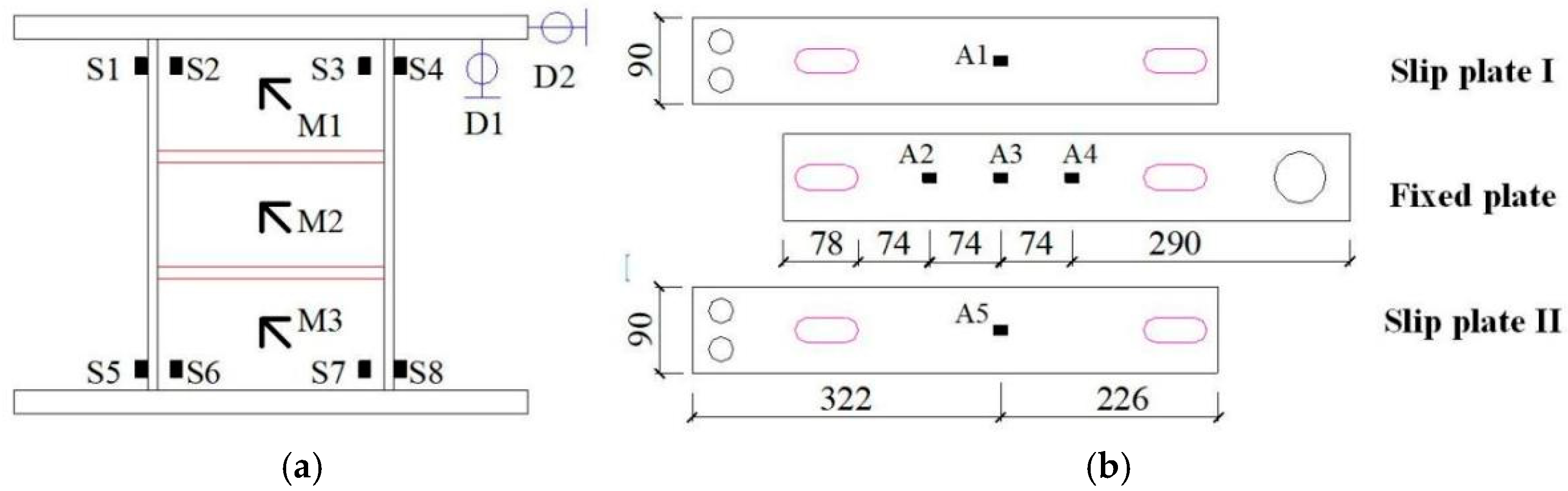
Throughout the loading process, the load values of the VSSL-SSBC-1 and SC-SL-1 specimens were directly recorded by the actuator, while the displacement and strain measurements were taken as shown in Figure 8.
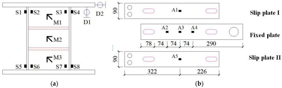
Figure 8.
Location of displacement and strain gauges: (a) VSSL-SSBC; (b) SCB.
(1) Displacement measurement. To ensure synchronized displacement measurements for both the VSSL-SSBC and SCB, a horizontal displacement gauge (D1) and a vertical displacement gauge (D2) were installed on the right side of the upper endplate of the VSSL, as shown in Figure 8a.
3.2. Failure Mode
3.2.1. VSSL-SSBC-1 Specimen
Figure 9 illustrates the failure mode of the VSSL-SSBC-1 specimen throughout the entire cyclic loading sequence. Red boxes in Figure 9 are center line of sliding plates. At the initial stage, all high-strength bolts were aligned with the centers of the slot holes (Figure 9a). During the first three loading steps, since the applied displacement was less than 0.5S1, the high-strength bolts only slid within the slot holes without reaching the ends. At this stage, only slippage occurred in the SSBC to dissipate the seismic energy, while the VSSL did not yield. After the fourth loading step, when the applied displacement exceeded 0.5S1, the high-strength bolts in the SSBC slid to the ends of the slot holes, and the VSSL began to yield in the positive direction, as shown in Figure 9b. At this stage, the bolts in the SSBC no longer slid, and the VSSL began to dissipate seismic energy through shear deformation. Subsequently, during the negative displacement cycle, the high-strength bolts in the SSBC slid to the negative end of the slot holes, causing the VSSL to yield in the negative direction, as shown in Figure 9d. Additionally, when the applied displacement exceeded 0.5S1, the VSSL experienced both web and flange buckling in the positive and negative loading directions, as illustrated in Figure 9c–e. Finally, when the applied displacement reached −0.5S1−0.09e in positive tension, a severe buckling and fracture developed between the flange and the endplate of the VSSL with a force of −404.45 kN, leading to specimen failure and termination of the loading process, as shown in Figure 9f. The SSBC remained undamaged throughout the entire test process.
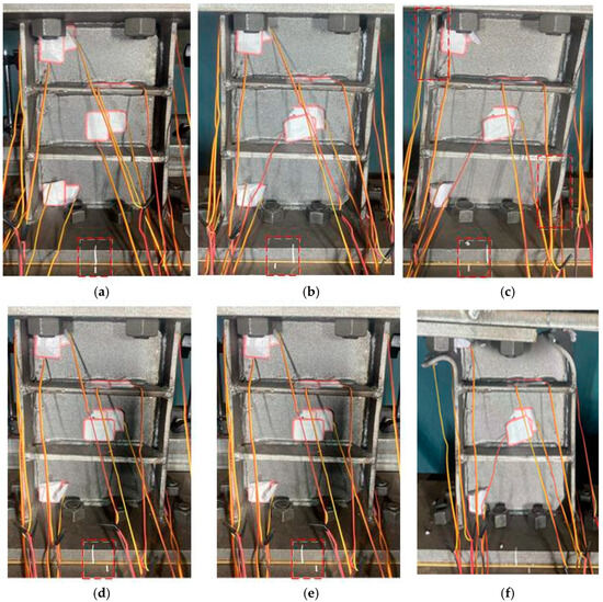
Figure 9.
Failure model of VSSL-SSBC-1 specimen (+,− are the positive and negative loading): (a) Initial stage; (b) Web yielding (+); (c) Flange buckling (+); (d) Web yielding (−); (e) Flange buckling (−); (f) Failure mode.
3.2.2. SC-SL-1 Specimen
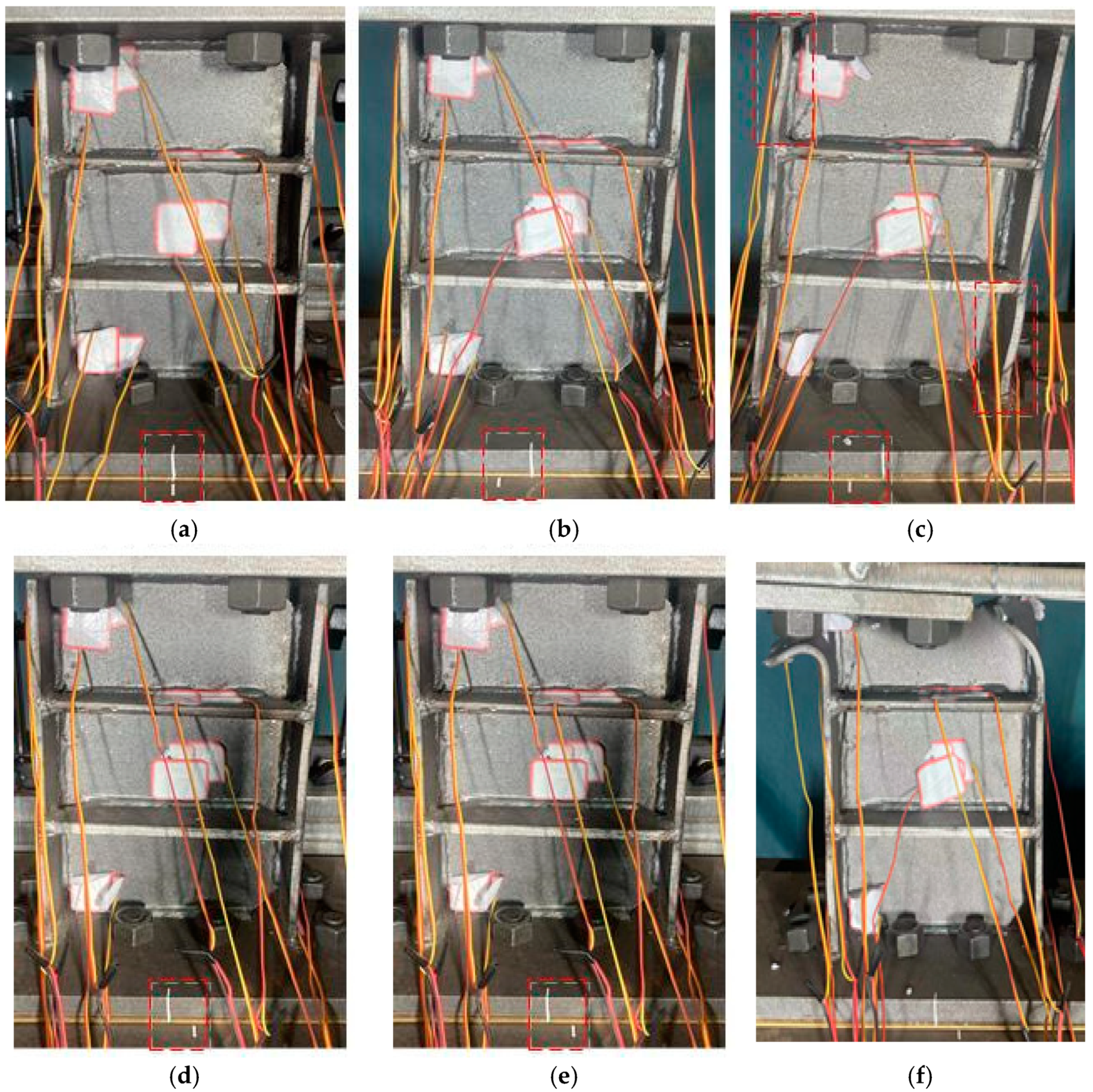
Figure 10 illustrates the deformation and failure modes of the SC-SL-1 specimen throughout the entire loading sequence. Red squares and ovals in Figure 10 are center line of sliding plates and concentrated damage, respectively. The primary failure modes include VSSL slip, yielding, and flange and web buckling. At the initial stage, the slip plates in the SCBs underwent notable deformation, with the SMA in tension. At this stage, the displacement of the slip plates matches that of the VSSL, as shown in Figure 10a. When the VSSL slipped to the end of the slot hole, the lateral deformation of the VSSL is zero (Figure 10d). At this stage, the SSBC and SCB exerted their energy dissipation capabilities, while the VSSL was not in an operating state. As the loading displacement was increased to 25.25 mm, the deformation of the slip plates within the SCB intensified, while the load-bearing and energy-dissipating capacities of the SMA wires were gradually enhanced, as shown in Figure 10b. Meanwhile, the VSSL transitioned to an elastic-plastic state, exhibiting pronounced inelastic deformation, as illustrated in Figure 10e. At this stage, the bolts in the SSBC slid to the ends, while the VSSL began to dissipate seismic energy through shear deformation and the SMA dissipated seismic energy through tensile deformation. At a loading displacement of 40.45 mm, the deformation of the slip plates in the SCBs became approximately equal to the loading displacement, indicating that the SMA wires contribute significantly to the load-bearing and restoring forces of the SC-SL system. Additionally, the vertical brace provides sufficient support to the SCB, as illustrated in Figure 10c. At this stage, both the web and flange of the VSSL entered a buckling state, resembling the failure mode of the VSSL observed in VSSL-SSBC-1, as shown in Figure 10f. At this point, the deformation capacity of the SMA wires reached its limit, leading to wire fracture and termination of the loading process. The vertical braces remained undamaged throughout the entire test process.
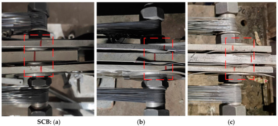

Figure 10.
Failure model of SC-SL-1 specimen: (a) d = 16 mm; (b) d = 25.25 mm; (c) d = 40.25 mm; (d) Initial slip; (e) Web yielding; (f) Web and flange buckling.
3.3. Hysteresis Performance
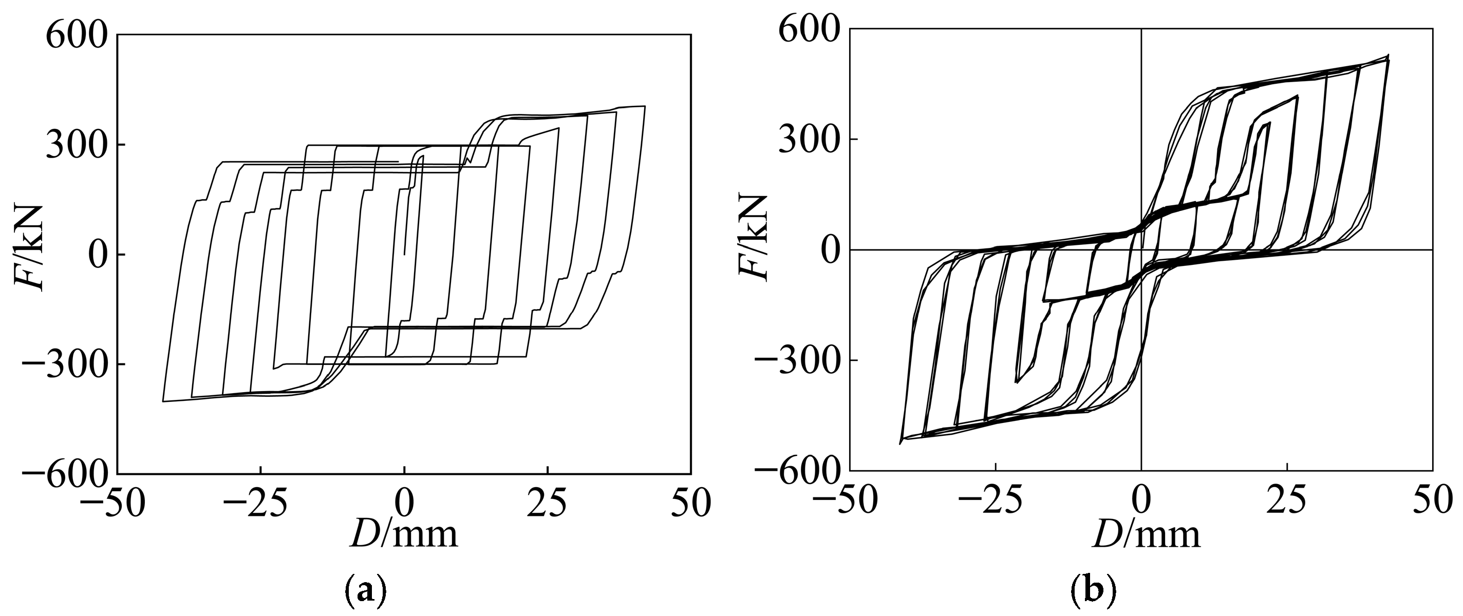
Figure 11 presents the hysteresis curves of the VSSL-SSBC-1 and SC-SL-1 specimens, where F and D represent the shear force and loading-displacement of the specimen, respectively. For the VSSL-SSBC-1 specimen (Figure 11a), when the displacement is less than 0.5S1, the hysteresis curve exhibits an ideal rectangular shape. As the displacement exceeds 0.5S1, the hysteresis curve becomes increasingly full, with the load gradually increasing as the displacement grows. Throughout the entire loading process, the specimen maintains its load-bearing capacity without any noticeable decline before failure. However, as the displacement increases, the slip force of the specimen gradually decreases, primarily due to the reduction in the friction coefficient of the shims.
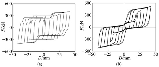
Figure 11.
Hysteresis curves of VSSL-SSBC-1 and SC-SL-1 specimens: (a) VSSL-SSBC-1; (b) SC-SL-1.
For the SC-SL-1 specimen (Figure 11b), at an ultimate displacement of 40.45 mm, the high-strength bolts within the SSBC reach the end of the slot holes, marking the transition of the VSSL into the energy-dissipating and load-bearing stage. The hysteresis curve is formed by the contributions from the VSSL-SSBC and the SCB. At this stage, the load-bearing capacity of SC-SL-1 shows a positive correlation with the displacement, reaching a peak load of 525.25 kN, with a residual deformation of 26.58 mm. Compared to the corresponding VSSL-SSBC-1 specimen, the SC-SL-1 specimen exhibits a remarkable improved load-bearing capacity and reduced residual deformation, indicating that the self-centering shear link possesses superior load-bearing and self-centering capabilities.
3.4. Skeleton Curves
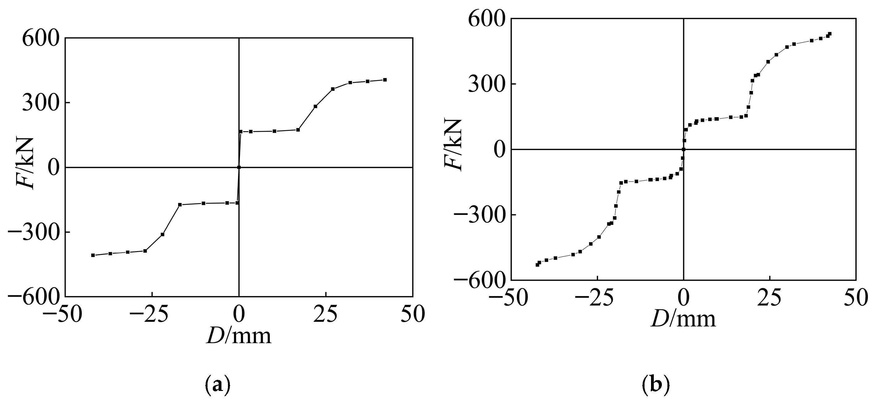
Figure 12 shows the skeleton curves of the VSSL-SSBC-1 and SC-SL-1 specimens. The VSSL-SSBC-1 specimen undergoes four stages, as shown in Figure 12a: elasticity, slip, elastic-plasticity, and plasticity. The slip displacement is 17 mm, corresponding to a slip load of 175.00 kN, which is mainly caused by the SSBC. The load capacity of the VSSL-SSBC-1 specimen is composed of the VSSL and SSBC, which is 442.30 kN, closely matching the calculated ultimate shear force for the VSSL in Equation (2).
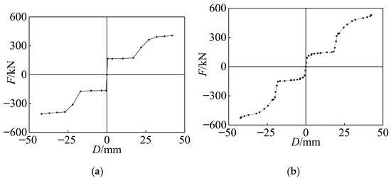
Figure 12.
Skeleton curves of VSSL-SSBC-1 and SC-SL-1 specimens: (a) VSSL-SSBC-1; (b) SC-SL-1.
The skeleton curve of the SC-SL-1 specimen, as shown in Figure 12b, includes three stages: elasticity, elastic-plasticity, and strengthening. After the high-strength bolt slides to the end of the slot hole, the load capacity increases significantly. The load capacity of the SC-SL-1 specimen is composed of the VSSL, SSBC, and SCBs, which is 529.18 kN and is notably higher than the load capacity of the VSSL-SSBC-1 specimen. This increase is mainly due to the enhanced load capacity provided by the self-centering SMA braces.
4. Numerical Study of VSSL-SSBC and SC-SL
4.1. Numerical Analysis Method
In the finite element model, it is assumed that the SMA remains in a superelastic state before fracture, and the friction coefficient of the shims in the SSBC remains constant under cyclic loading. The material properties, boundary conditions, etc., are consistent with those in the experiment.
4.1.1. Verification of the SMA
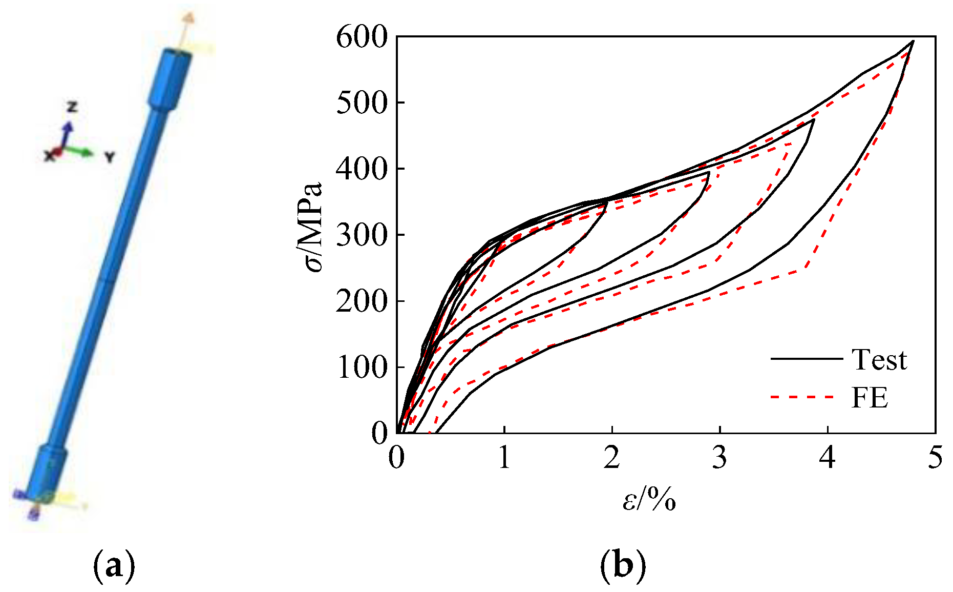
The UMAT program was used to simulate the constitutive curve of the SMA material. An SMA bar with a diameter of 6 mm (No. 10/6-450-30) tested by Li [33] was used to validate the SMA numerical model, as shown in Figure 13a. One end of the SMA finite element model is fixed, and a cyclic displacement load is applied to the other end. The hysteresis curves of the experiment and the finite element analysis are shown in the figure. The hysteresis curves from both the experiment and the finite element analysis are flag-shaped, and their mechanical behaviors are consistent, indicating that the SMA constitutive model is reliable.

Figure 13.
Verification of the SMA material: (a) Finite element model; (b) Hysteresis curves.
4.1.2. Numerical Method of VSSL-SSBC-1 Specimen
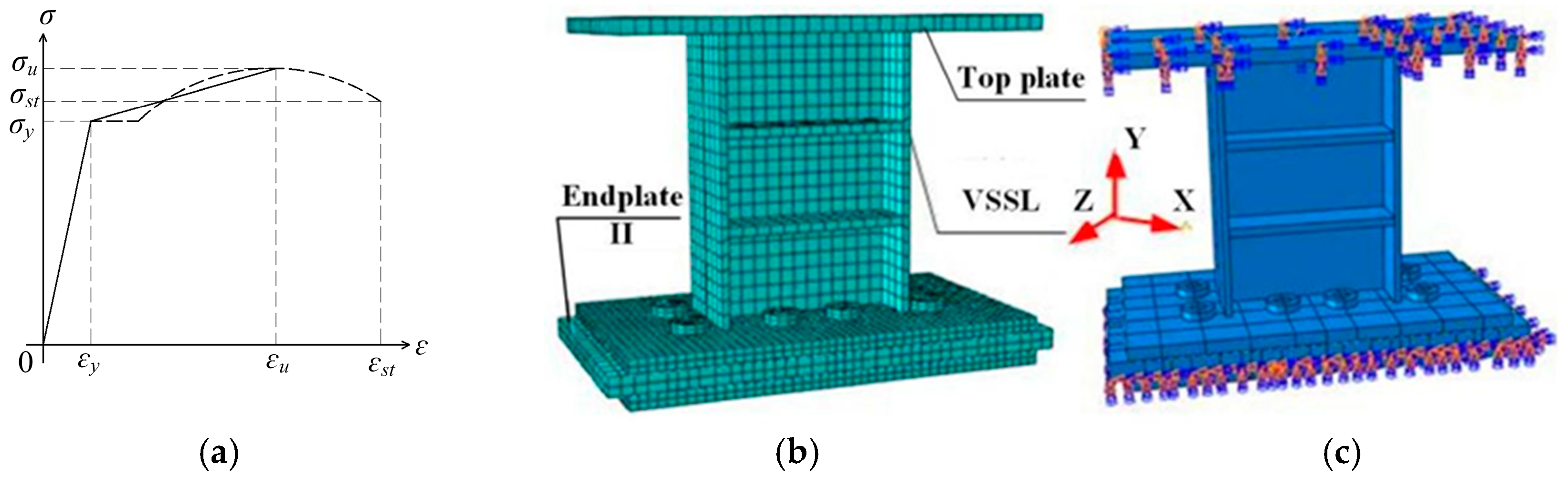
(1) Material properties. In the VSSL-SSBC model, the material properties of the steel plates with different thicknesses are listed in Table 2. The constitutive curves of all steel models are shown in Figure 14a, which is bilinear constitutive model.
(2) Mesh quality. The numerical analysis of the VSSL-SSBC was performed using ABAQUS software. The C3D8R element, an eight-node three-dimensional solid element, is capable of modeling large deformation and strains, enabling the accurate simulation of various structural components. The mesh quality of the VSSL-SSBC-1 specimen is shown in Figure 14b.
(3) Boundary conditions. For the VSSL-SSBC-1 specimen, the degrees of freedom at both end sections of endplate II are constrained. The friction coefficient between endplate I in VSSL and endplate II is set to 0.30, while the coefficient between endplate II and the base plate is 0.075. Additionally, the displacement in the X direction on the upper surface of the top plate is released, while rotation in the Z direction is constrained. Figure 14c shows the boundary conditions of the VSSL-SSBC-1 specimen.
(4) Loading protocol. In the numerical analysis, applying a horizontal displacement to the top plate of the VSSL ensures that the bending moment and shear force align with the loading conditions in an eccentrically braced frame. The specific loading protocol is detailed in Section 3.1.3. Based on this approach, the VSSL-SSBC-1 specimen can be effectively analyzed using numerical analysis methods.

Figure 14.
Numerical model of VSSL-SSBC-1 specimen: (a) Constitutive curve; (b) Analytical model; (c) Boundary condition.
Figure 14.
Numerical model of VSSL-SSBC-1 specimen: (a) Constitutive curve; (b) Analytical model; (c) Boundary condition.
4.1.3. Numerical Method of SC-SL-1 Specimen
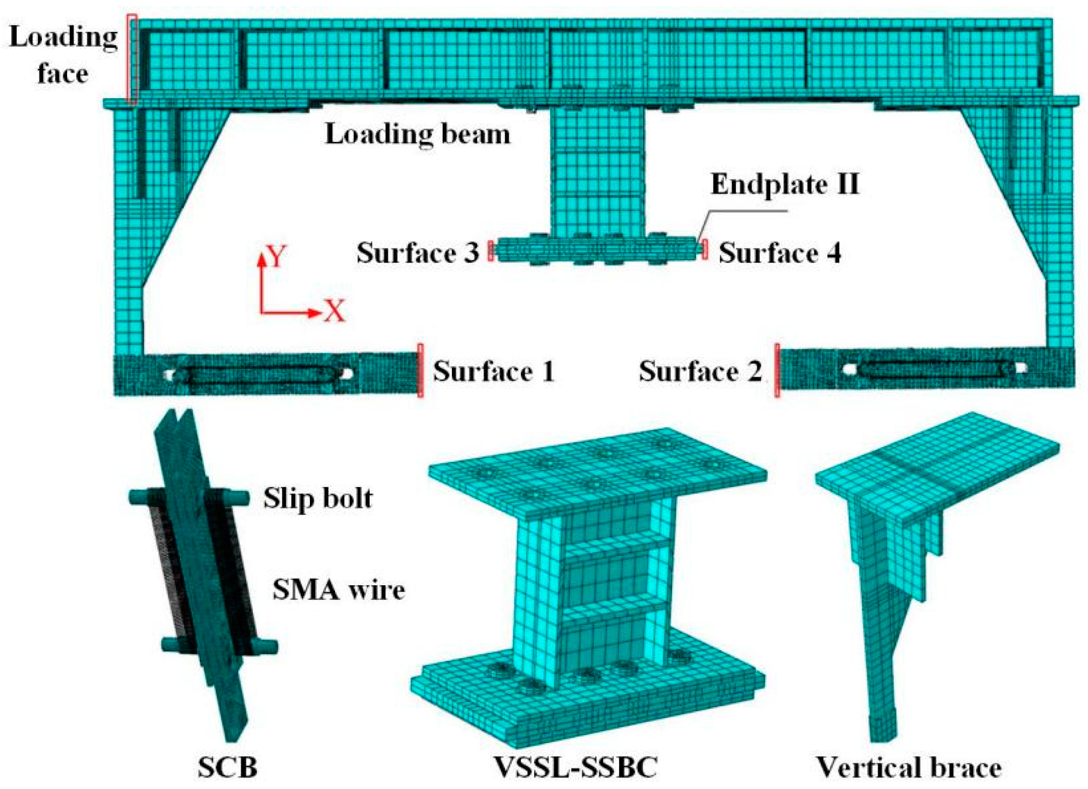
The self-centering shear link primarily consists of two SCBs, a VSSL-SSBC, a loading beam, and two vertical braces, as shown in Figure 14. In the numerical model, all components are simulated using C3D8R elements in the ABAQUS software, consistent with the VSSL-SSBC-1 specimen.
(1) Material properties. The material properties of each component are detailed in Table 2, and the constitutive curves of all steel models are shown in Figure 14a.
(2) Mesh quality. The mesh quality of the SC-SL-1 specimen is shown in Figure 15.
(3) Boundary conditions. In the SC-SL-1 specimen, the displacements in all directions of all nodes at surfaces 1 and 2 of the two SCBs must be constrained. Likewise, the displacements in all directions of all nodes at surfaces 3 and 4 on both sides of endplate II in the VSSL-SSBC must also be constrained. Additionally, all components must have their out-of-plane displacement restricted in the XY plane.
(4) Loading protocol. A cyclic displacement in the X direction is applied to the left loading surface of the loading beam, with displacement increments following those described in Section 3.1.3. With the appropriately defined elements, material properties, boundary conditions, and loading protocols, a comprehensive numerical simulation analysis can be conducted.

Figure 15.
Numerical model of SC-SL-1 specimen.
Figure 15.
Numerical model of SC-SL-1 specimen.
4.2. Comparison of VSSL-SSBC-1 Specimen
4.2.1. Hysteresis Curves
Figure 16a presents the hysteresis curves obtained from the test and numerical analysis for the VSSL-SSBC-1 specimen. In the numerical results, the hysteresis curve also follows four stages: elastic, slippage, elastoplastic, and plastic. A discrepancy in the bearing capacity is observed between the test and numerical analysis results during the slippage stage, primarily due to the cyclic friction in the shim under cyclic loading, which gradually reduces the friction coefficient. However, during the load-bearing stage of the VSSL, both methods yield nearly identical bearing capacities and displacement. At ultimate displacement, the maximum loads recorded from the test and numerical analysis are 404.45 kN and 409.97 kN, respectively, with a marginal error of 1.36%. This demonstrates that the numerical results closely align with the test results in terms of load-bearing capacity, stiffness, and overall structural response across different loading stages.
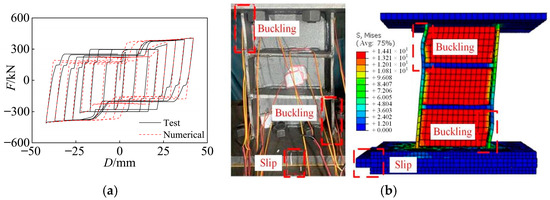
Figure 16.
Comparison of hysteresis curves and failure modes for VSSL-SSBC-1 specimen: (a) Hysteresis curves; (b) Failure modes.
4.2.2. Failure Modes
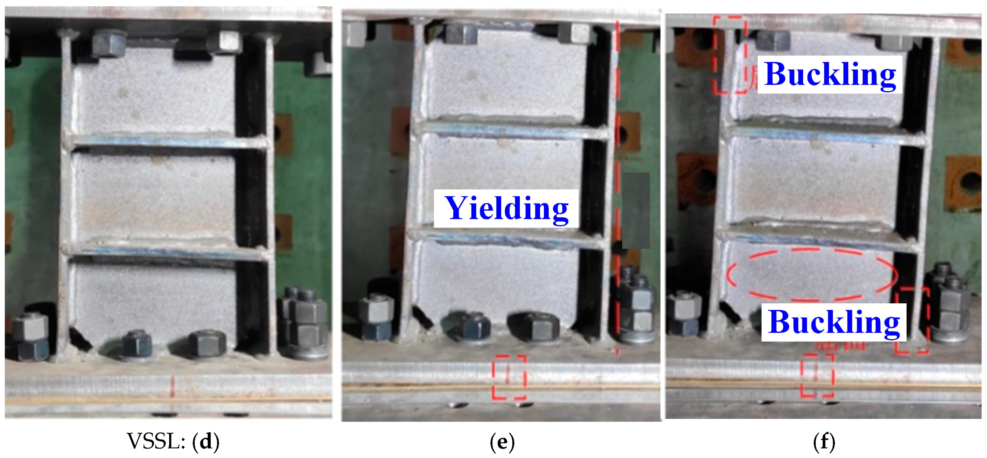
Figure 16b illustrates the failure mode of the VSSL-SSBC-1 specimen under cyclic loading, as determined by numerical analysis. The results indicate that the initial deformation is attributed to the frictional slippage of the high-strength bolts. As loading progresses, the VSSL begins to yield and sustain the load, followed by buckling of the flange and web, which is consistent with expectations. Additionally, the highest stress concentrations in VSSL-SSBC-1 occur at the connection between the flange and web, where failure is most likely to initiate. This confirms that the failure modes in the test and numerical analysis are highly consistent.
4.3. Comparison of SC-SL-1 Specimen
4.3.1. Hysteresis Curves
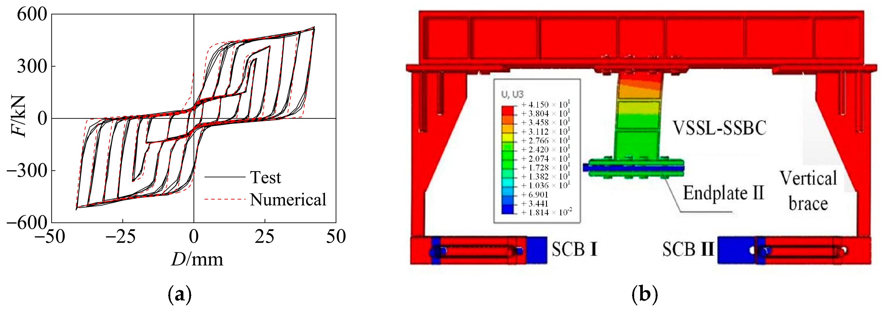
A numerical model of the SC-SL-1 specimen was developed and analyzed, and the resulting hysteresis curve was compared with the test results, as shown in Figure 17a. The loading displacement, stiffness, and bearing capacity at each loading step exhibit close agreement. When SC-SL-1 reaches the maximum loading displacement, the ultimate load values obtained from the numerical analysis and test are 535.23 kN and 519.28 kN, respectively, with a minimal discrepancy of only 3.07%. This confirms that the numerical analysis method for the self-centering shear link can accurately predict its bearing capacity.
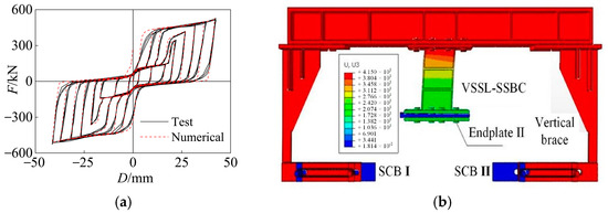
Figure 17.
Comparison of hysteresis curves and failure modes for SC-SL-1 specimen: (a) Hysteresis curves; (b) Failure modes.
4.3.2. Failure Modes
As shown in Figure 17b, endplate II of the VSSL-SSBC is fixed, and the VSSL undergoes inelastic deformation, bearing, and energy dissipation under cyclic loading. The displacement of the VSSL-SSBC matches that of the SC-SL, aligning with Figure 10d–f. Driven by the vertical brace, the SCB induces movement and superelastic deformation in both the slip plate and SMA. As the displacement increases, the SMA’s bearing capacity and restoring force progressively increase, contributing to both energy-dissipating and self-centering functionality in the SC-SL, consistent with the deformation mode depicted in Figure 10a–c.
5. Seismic Performance of EBF with Self-Centering Shear Link
5.1. Analysis Model
5.1.1. Modeling
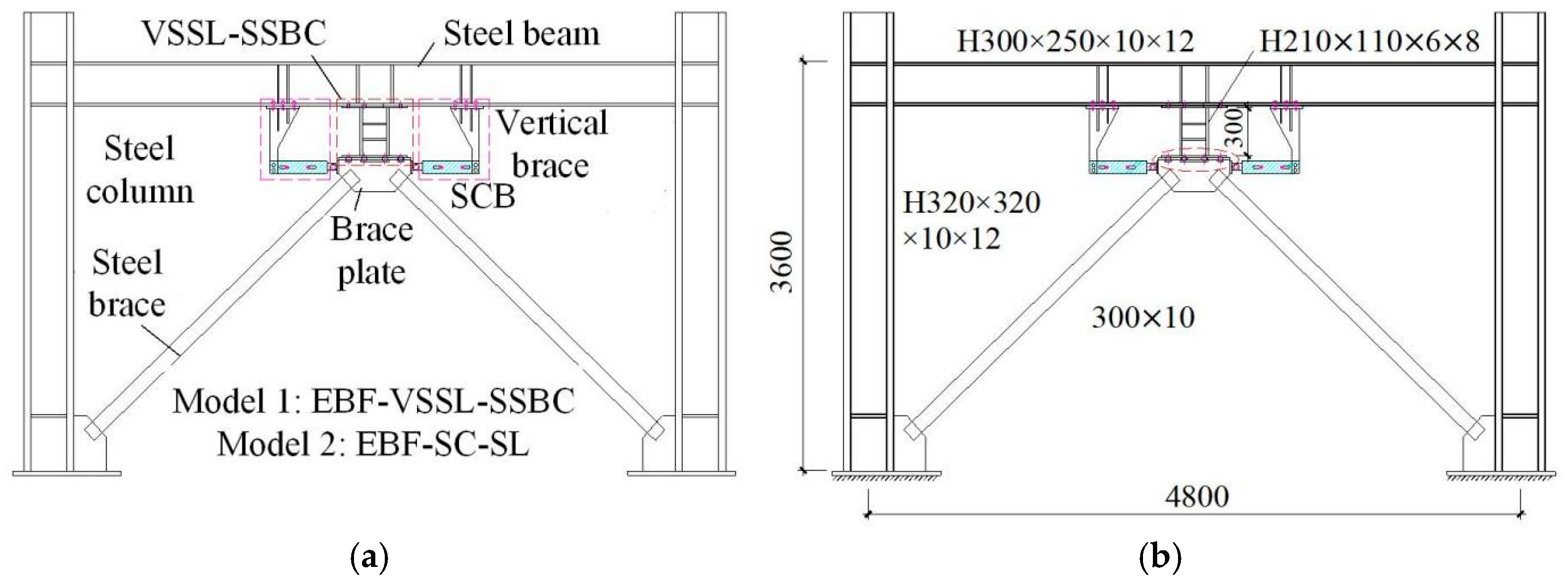
An eccentrically braced steel frame (EBF) with a VSSL-SSBC system (Model 1: EBF-VSSL-SSBC) and another EBF structure with an SC-SL system (Model 2: EBF-SC-SL) are designed. Both models are composed of steel columns, steel beams, steel braces, the VSSL-SSBC/SC-SL component, and brace plates, as illustrated in Figure 18a. The main distinction between the two models lies in the fact that in Model 2, two self-centering SMA braces (SCBs) and two vertical braces are installed on either side of the brace plate. As shown in Figure 18b, both models have a span of 4800 mm and a height of 3600 mm. The steel columns are H320 mm × 320 mm × 10 mm × 12 mm, the steel beams are H300 mm × 250 mm × 10 mm × 12 mm, and the steel braces are square steel tubes measuring 300 mm × 10 mm.
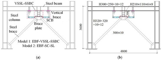
Figure 18.
Analysis models of EBF-VSSL-SSBC and EBF-SC-SL: (a) Basic components; (b) Details.
In the VSSL-SSBC, the VSSL component has dimensions of H210 mm × 110 mm × 6 mm × 8 mm with a length of 210 mm. It is connected at both the upper and lower ends using eight M22 high-strength bolts. A pretension force of 155 kN is applied at the upper end and 30 kN at the lower end. The length of the slot hole is 50 mm. The friction coefficient between the upper end of the brace plate and the lower end of the VSSL is 0.20, while the coefficient between the upper end of the brace plate and the base plate is 0.075. Additionally, in Model 2, the SCB has a length of 700 mm, with an SMA area of 219.80 mm2. Other parameters for the vertical brace and the SCB are the same as those outlined in Section 3.1.1.
5.1.2. Numerical Analysis Method
The EBF-VSSL-SSBC and EBF-SC-SL specimens were comprehensively investigated using the ABAQUS software. The steel columns, steel beams, steel braces, VSSL-SSBC/SC-SL, brace plates, high-strength bolts, and self-centering SMA braces were all modeled using C3D8R elements. Additionally, the friction behavior between the plates in the VSSL-SSBC and the SCB was simulated by defining the appropriate friction coefficient, as shown in Section 4.1. The material properties of all components are detailed in Section 3.1.2.
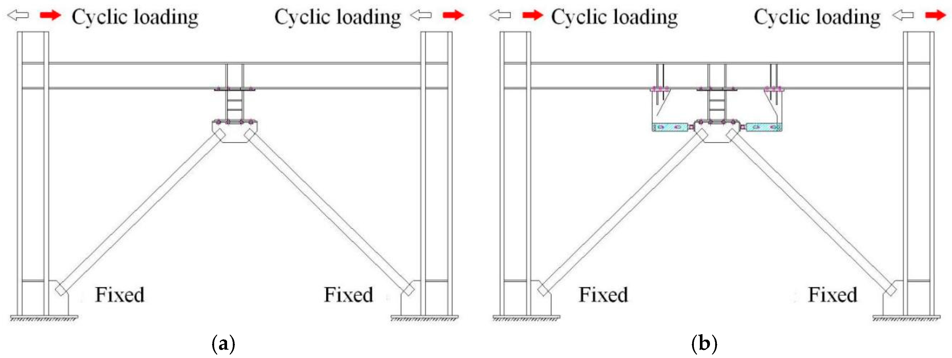
As shown in Figure 19, the boundary conditions of the two EBF models are as follows: the column bases are constrained, and out-of-plane displacement of the EBFs is restricted throughout the entire loading process. A displacement-controlled load protocol is applied to the top ends of the two steel columns, following the same loading method as that of the VSSL-SSBC described in Section 3.1.3.
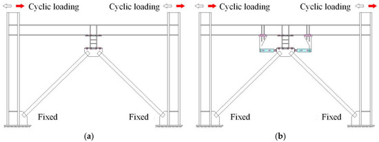
Figure 19.
Numerical analysis method of EBF-VSSL-SSBC and EBF-SC-SL: (a) EBF-VSSL-SSBC; (b) EBF-SC-SL.
5.2. Frequent Earthquakes
The loading displacements of the designed EBFs during frequent and rare earthquakes were determined at the inter-storey drifts of 0.4% and 2.0% [9], respectively.
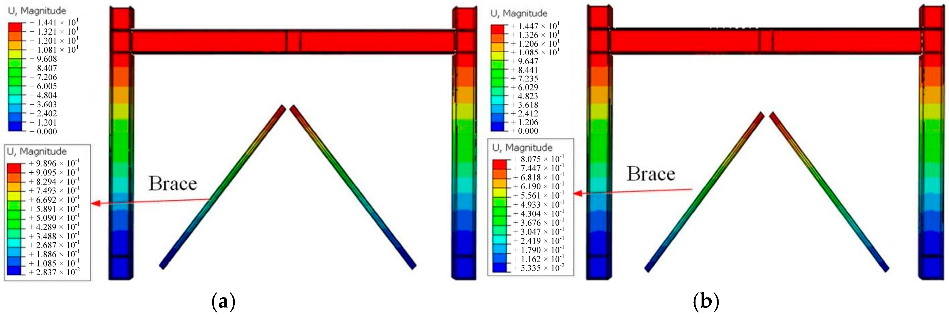
5.2.1. Deformation Modes
Under frequent earthquakes, the expected displacement values of both EBF-VSSL-SSBC and EBF-SC-SL are 14.40 mm. Figure 20 illustrates the deformation modes of the two steel frames and braces, revealing that the maximum displacement occurs at the top end of the steel frame and braces. Due to the low friction coefficient and small pretension of the SSBC, the bearing capacity during the slippage of VSSL is relatively low. Consequently, when the frames reach the expected displacement value, the deformation of the braces remains minimal, with the maximum displacement of the braces in both EBF-VSSL-SSBC and EBF-SC-SL being only 0.22 mm. This suggests that the deformation modes of the frames and braces in both EBFs are essentially the same.

Figure 20.
Deformation modes of the steel frame and brace during frequent earthquakes: (a) EBF-VSSL-SSBC; (b) EBF-SC-SL.
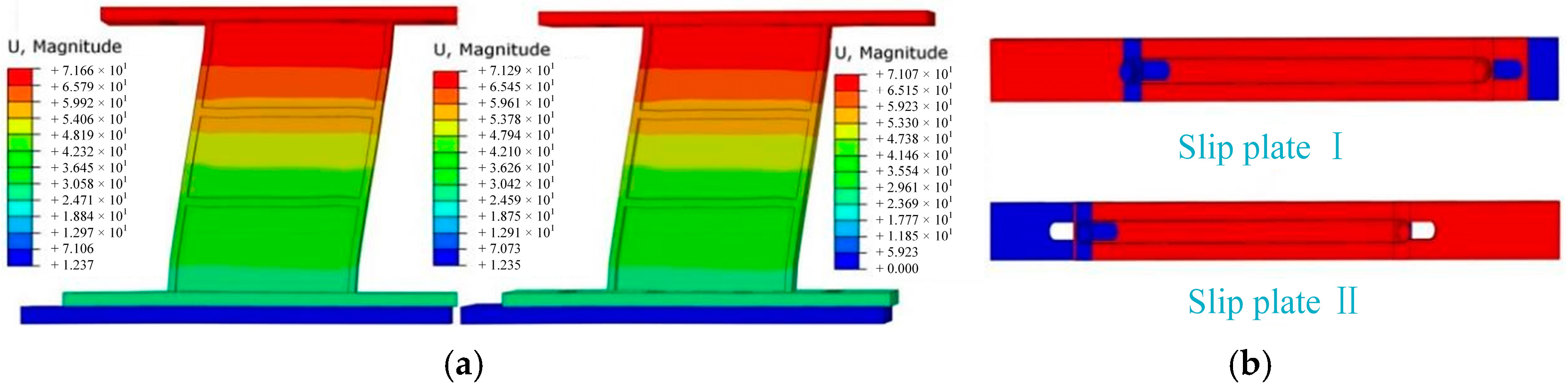
Figure 21 presents the deformation modes of the VSSL and the SCBs. Due to the slippage of the high-strength bolts in the VSSL-SSBC, the overall slippage values of the VSSL in both EBFs are 14.40 mm, meaning that there is no significant relative slippage between the two ends of the VSSL, which is in line with expectations. Additionally, when the EBF-SC-SL reaches the expected maximum displacement, the vertical brace drives the slip plates and slip bolts to move, leading to the tension of the SMA wires with an elongation of 14.40 mm. Therefore, the deformation modes of the VSSL in both EBFs are completely identical, and the deformation mode of the SCBs also meets the expectations.
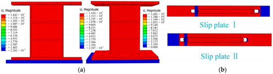
Figure 21.
Deformation modes of the VSSL-SSBC and SCB during frequent earthquakes: (a) VSSL-SSBC; (b) SCB.
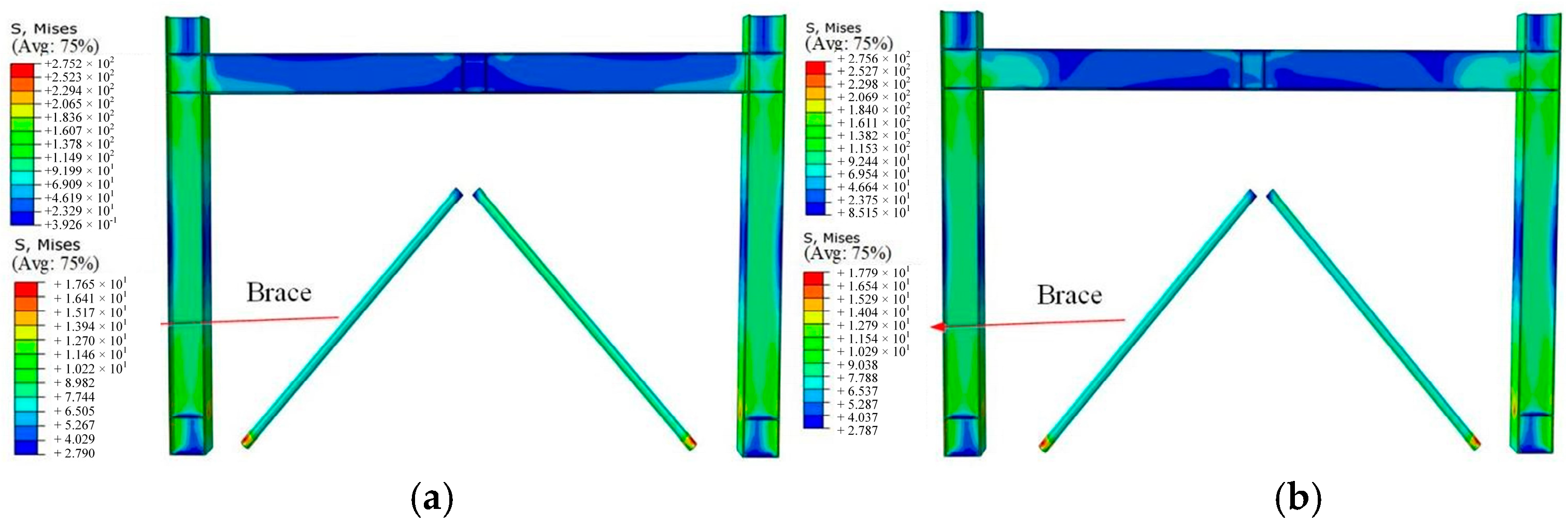
5.2.2. Stress Nephograms
Figure 22 illustrates the stress nephograms of the steel frame and braces in both EBFs under the expected maximum displacement. For the EBF-VSSL-SSBC and EBF-SC-SL, the maximum stresses in the steel frame are 275.20 MPa and 275.60 MPa, respectively, and the maximum stresses in the braces are 16.13 MPa and 17.79 MPa, respectively. These values are remarkably close to each other. All of these stress values are below the yield stress of the steel and braces, indicating that these components stay within an elastic range. Additionally, owing to the low slip resistance of the SSBC, the initial slip load and stiffness of the VSSL-SSBC are relatively low, leading to reduced stress levels in the structural components.
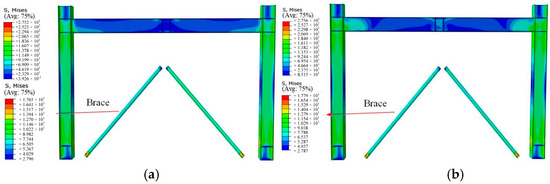
Figure 22.
Stress nephograms of the steel frame and brace during frequent earthquakes: (a) EBF-VSSL-SSBC; (b) EBF-SC-SL.
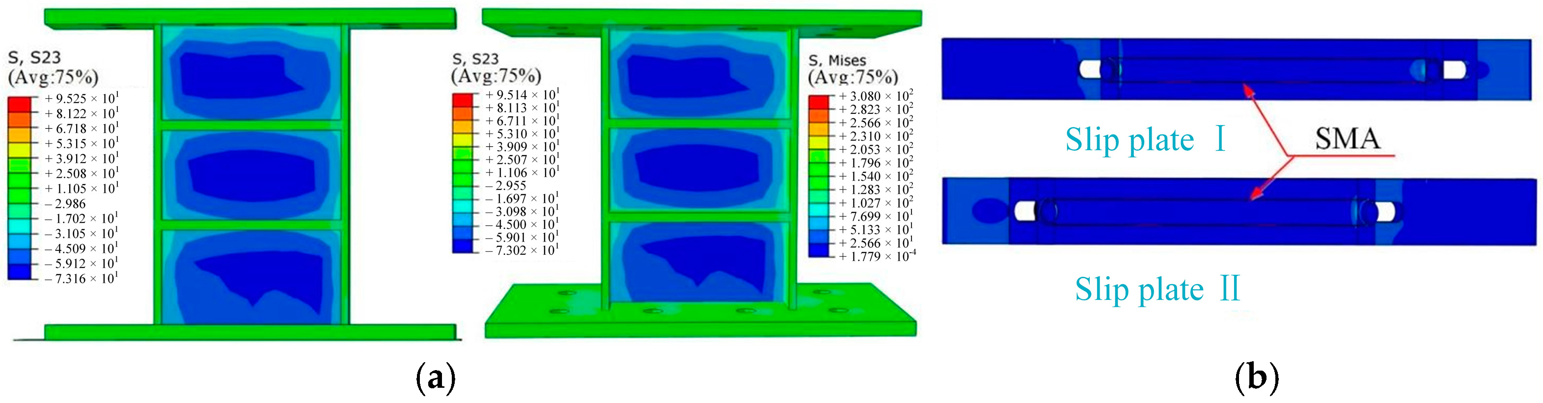
Figure 23 presents the maximum shear stress of the VSSL and the stress nephograms of the SCB under frequent earthquakes. Since the SSBC has a low initial frictional slip load and the VSSL remains in the slip stage, the maximum shear stress of the VSSL-SSBC in both EBFs is 73.10 kN, which is significantly lower than the yield shear stress of the VSSL. In the EBF-SC-SL, the maximum stress of the SMA reaches 308.00 MPa, indicating that the SMA has entered its working state, effectively contributing to the energy dissipation and self-centering capabilities.
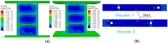
Figure 23.
Stress nephograms of the VSSL-SSBC and SCB during frequent earthquakes: (a) VSSL-SSBC; (b) SCB.
5.2.3. Hysteresis Curves
Figure 24 presents the hysteresis curves of the EBFs under frequent earthquakes. When the displacement reaches 14.40 mm, the maximum bearing capacities of EBF-VSSL-SSBC and EBF-SC-SL are 420 kN and 504 kN, respectively. This indicates that the EBF with SC-SL has a higher bearing capacity than the one with VSSL-SSBC, along with a significantly improved energy dissipation capacity. Additionally, the residual deformation values of EBF-VSSL-SSBC and EBF-SC-SL are 2.99 mm and 1.32 mm, respectively, demonstrating that the EBF equipped with SCBs exhibits a superior self-centering capability.
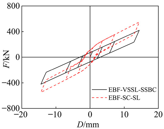
Figure 24.
Hysteresis curves of the EBFs during frequent earthquakes.
Based on the above analysis, under frequent earthquakes, the stress and displacement values of the steel frame, braces, and VSSL in both EBF-VSSL-SSBC and EBF-SC-SL are essentially the same. However, the incorporation of SCBs effectively enhances the load-bearing capacity and reduces residual deformation in the EBF.
5.3. Rare Earthquakes
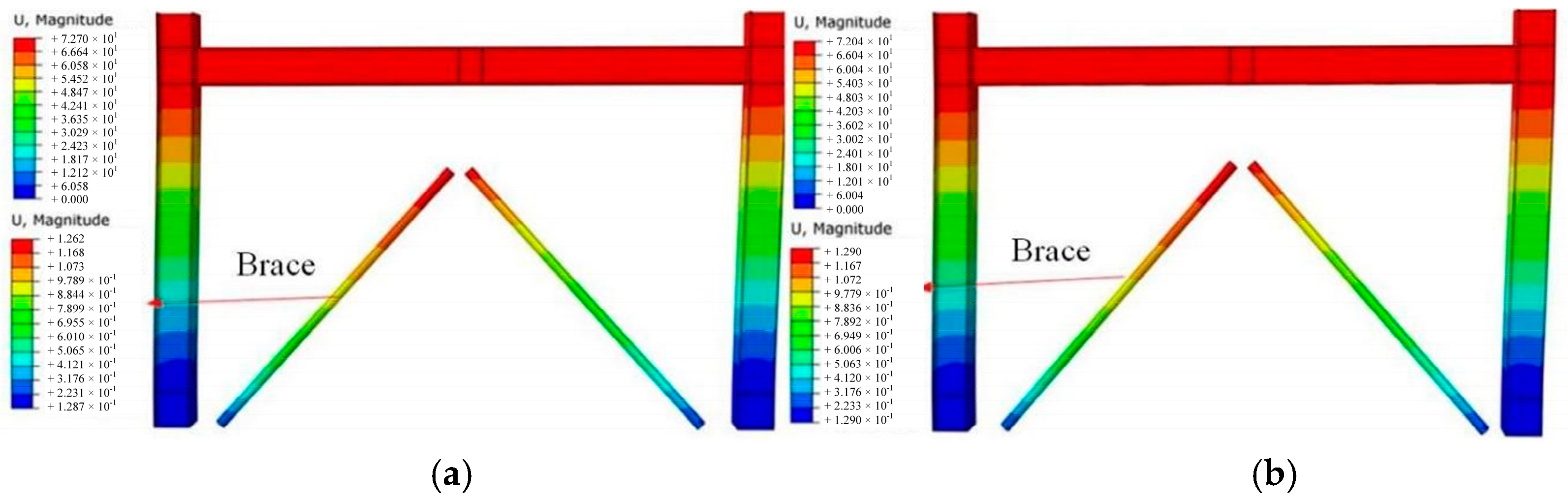
5.3.1. Deformation Modes
Under a rare earthquake, when both EBF-VSSL-SSBC and EBF-SC-SL reach the expected displacement of 72 mm, the deformation of the corresponding main frame and braces is shown in Figure 25. The deformation modes of the main frames in both EBFs are nearly identical. The maximum displacement at the upper end of the braces in the EBF-VSSL-SSBC and EBF-SC-SL are 1.26 mm and 1.29 mm, respectively, with similar deformation modes. However, the maximum displacement of the braces is significantly smaller than that of the frame, primarily because the braces are much stiffer than the VSSL-SSBC, causing the deformation to concentrate mainly in the VSSL.
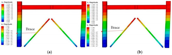
Figure 25.
Deformation modes of the steel frame and brace during a rare earthquake: (a) EBF-VSSL-SSBC; (b) EBF-SC-SL.
The deformation modes of the VSSL-SSBC and SCB in EBF-VSSL-SSBC and EBF-SC-SL under a rare earthquake are shown in Figure 26. Since the braces in both EBFs provide sufficient stiffness and bearing capacity for the corresponding VSSL, the displacement of the brace end plates connected to the lower end plates of the VSSL remains relatively small. The lower end plates experience a displacement of 25 mm (bolts sliding to the end of the slot hole), while the upper end plate displacement is approximately 72 mm, effectively reducing the relative deformation of the VSSL. Additionally, in the EBF-SC-SL, the side plates and sliding bolts on the SCB move approximately 72 mm, matching the elongation of the SMA wires.

Figure 26.
Deformation modes of the VSSL-SSBC and SCB during a rare earthquake: (a) VSSL-SSBC; (b) SCB.
5.3.2. Stress Nephograms
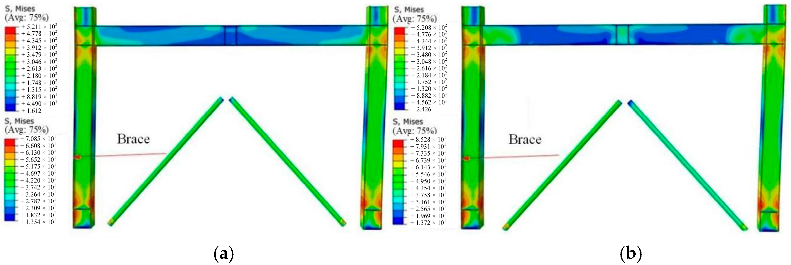
Under a rare earthquake, the stress nephograms of the main frame and braces in EBF-VSSL-SSBC and EBF-SC-SL are shown in Figure 27. The maximum stress values in the steel frames of the two EBFs are 521.10 MPa and 520.80 MPa, respectively, primarily concentrated at the beam–column joints and the bases of the columns, reaching the ultimate stress limit of the steel. The maximum stresses in the braces are 70.85 MPa and 85.28 MPa, respectively, which remain below the yield stress. Additionally, the brace stress in EBF-SC-SL is relatively higher due to the increased load-bearing capacity of the SCB, which amplifies the stress of the brace plates and the steel brace itself.
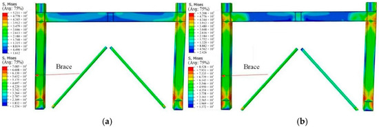
Figure 27.
Stress nephograms of the steel frame and brace during a rare earthquake: (a) EBF-VSSL-SSBC; (b) EBF-SC-SL.
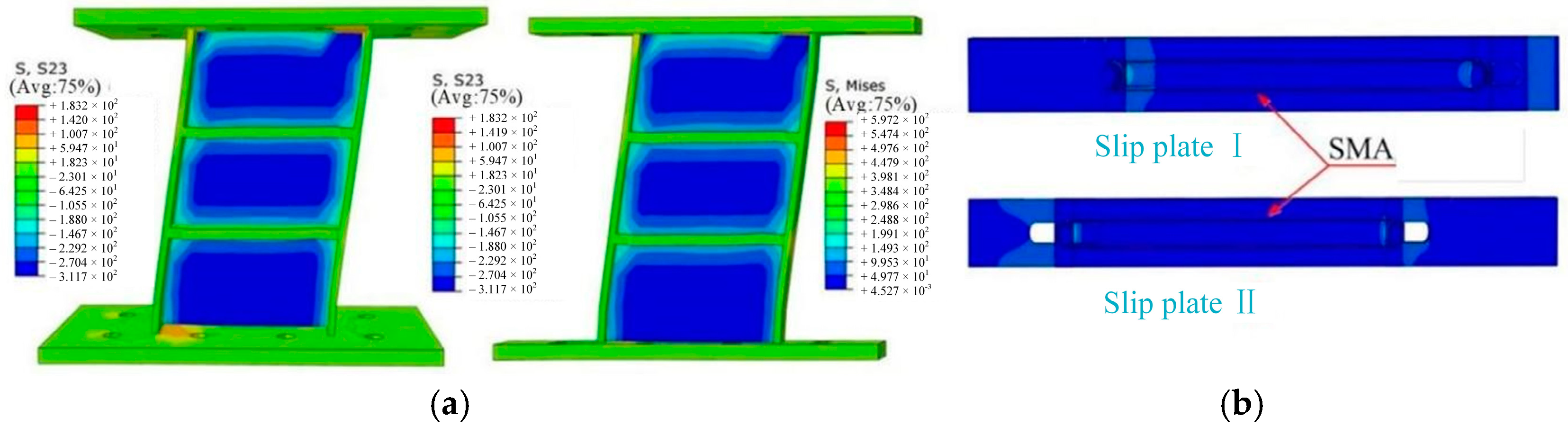
The stress nephograms of the VSSL and SCBs in EBF-VSSL-SSBC and EBF-SC-SL under a rare earthquake are shown in Figure 28. The shear stress distribution in the web of the VSSL is nearly identical in both EBFs, with a maximum stress of 311.70 MPa, reaching the ultimate shear stress limit and experiencing shear failure, which aligns with expectations. Furthermore, in the EBF-SC-SL, all components of the SCB remain in the elastic state, and the stress of the SMA reaches 597.20 MPa, staying within the superelastic range. This enables the structure to provide both energy-dissipating and self-centering capabilities.

Figure 28.
Stress nephograms of the VSSL-SSBC and SCB during a rare earthquake: (a) VSSL-SSBC; (b) SCB.
5.3.3. Hysteresis Curves
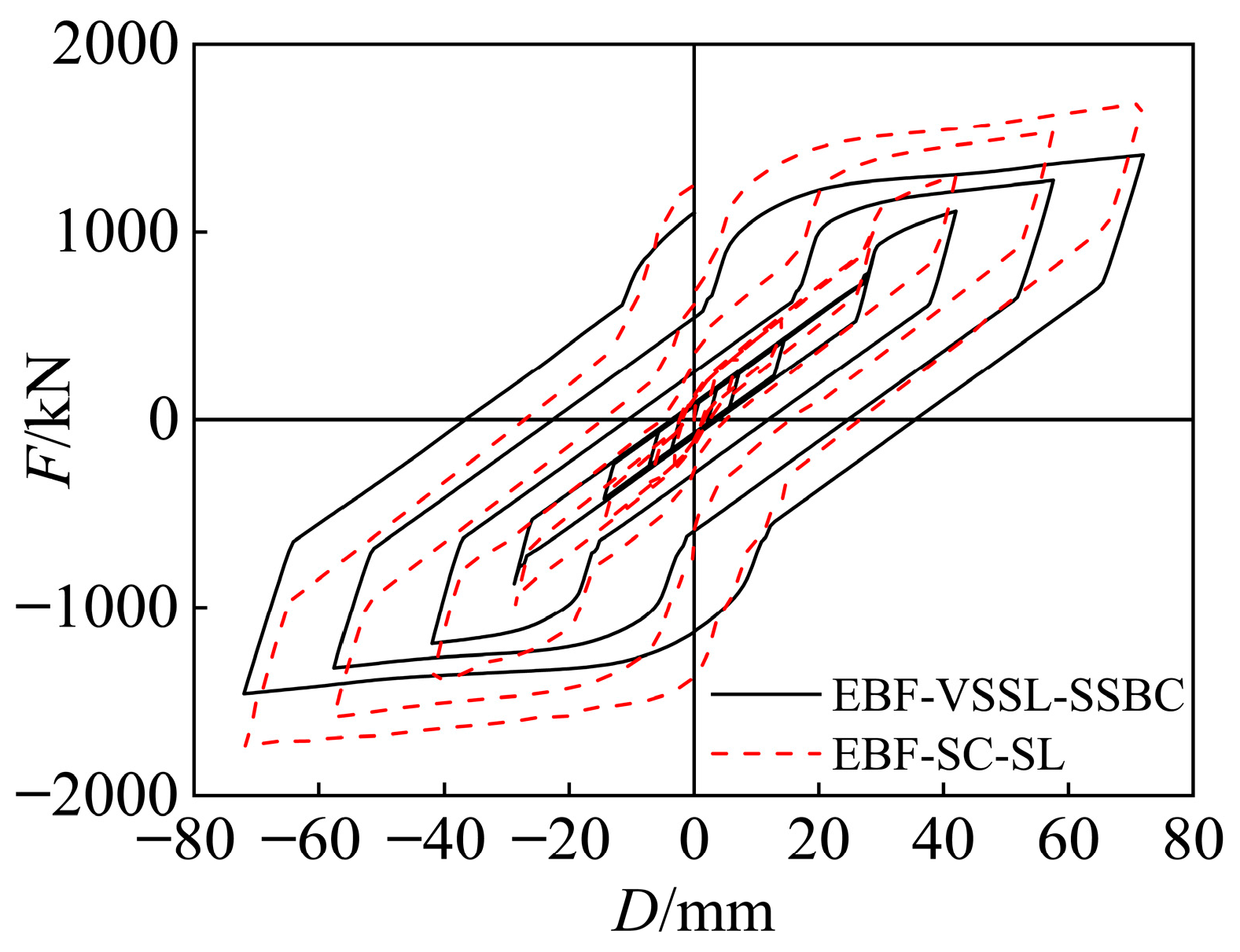
The hysteresis curves of EBF-VSSL-SSBC and EBF-SC-SL are shown in Figure 29, where their maximum bearing capacities are 1408.93 kN and 1685.94 kN, respectively, with an increase of 19.66%. This indicates that the incorporation of SCBs has a significant impact on the ultimate bearing capacity of the EBF. The hysteresis loop area at each loading step in EBF-VSSL-SSBC is larger than those in EBF-SC-SL, and the energy dissipation values of the last hysteresis loops of the two specimens are 186.7 kJ and 193.6 kJ, respectively, with an increase of 3.70%. Additionally, the maximum residual deformations of the EBF-VSSL-SSBC and EBF-SC-SL are 35.28 mm and 25.44 mm, respectively, with a reduction of 27.90% suggesting that the EBF-SC-SL exhibits better load-bearing and self-centering capabilities.

Figure 29.
Hysteresis curves for the EBFs during a rare earthquake.
Under a rare earthquake, the steel frames in both EBF-VSSL-SSBC and EBF-SC-SL yield, while the braces remain in the elastic state. The VSSL in both EBFs enters the plastic stage. However, in the EBF-SC-SL, the VSSL experienced smaller residual deformation after the earthquake, effectively enhancing the seismic resilience capacity of the EBF. In conclusion, a comparative analysis reveals that the EBF with a novel SC-SL demonstrates superior stiffness, load-bearing capacity, and self-centering performance.
5.4. Seismic Results Analysis
Table 3 presents the key analysis results of the EBFs during different earthquakes. Here, η represents the residual deformation, σS denotes the stress of the SMA wire, DF is the maximum displacement of the steel frame, DV refers to the relative deformation of VSSL, σF indicates the maximum stress of the steel frame, τV is the maximum shear stress of the VSSL, and DB and σB correspond to the maximum displacement of the brace and stress, respectively. Under various earthquake conditions, the frame stress and displacement, brace stress and displacement, and the VSSL stresses and displacements in EBF-VSSL-SSBC and EBF-SC-SL remain identical. However, under the same conditions, the residual deformation of EBF-SC-SL is significantly smaller than that of EBF-VSSL-SSBC, which is beneficial for the seismic resilience of the EBF.
Table 3.
Comparison with the results for the EBFs during different earthquakes.
6. Conclusions and Future Prospects
6.1. Conclusions
In this study, an eccentrically braced frame (EBF) with a novel self-centering shear link (SC-SL) was developed and investigated through test and numerical methods to enhance seismic resilience. The mechanical properties of VSSL-SSBC and SC-SL, along with the corresponding seismic performance of the EBFs were analyzed. The key findings are summarized as follows:
- (1)
- Under seismic loading, the VSSL-SSBC mainly experienced elastic, slip, elastoplastic, and plastic stages, while the SC-SL experienced VSSL slip, yielding, and flange and web buckling, with the SMA wires in tension. The ultimate bearing capacities of the two devices are 442.30 kN and 529.18 kN, respectively.
- (2)
- The experimental and finite element results demonstrate that the SC-SL has a significant improvement in both the ultimate bearing capacity and energy dissipation capacity compared with the VSSL-SSBC. Moreover, due to the function of the SCB, it exhibits an excellent self-centering capacity.
- (3)
- Under frequent earthquakes, the frame, brace, and VSSL stresses and displacements in EBF-VSSL-SSBC and EBF-SC-SL are basically equivalent. Both frames dissipate energy through the slippage of high-strength bolts, and VSSL-SSBC remains elastic without significant yielding deformation.
- (4)
- Under rare earthquakes, the bearing force and stress of the brace of the EBF-SC-SL are slightly increased compared with EBF-VSSL-SSBC. Its ultimate load capacity is enhanced by 19.66%, and the residual deformation is reduced by 27.90%. This improvement contributes to the seismic resilience capacity of the EBF.
6.2. Outlook
This paper effectively demonstrates that SC-SL has excellent self-centering ability and seismic performance. To conduct a further exploration, development, and application of this technology, the following contents can serve as future research topics:
- (1)
- In this paper, a method combining experiments and finite element verification is adopted to study the mechanical properties of SC-SL, which provides a reference for the design of self-centering structures. However, it is necessary to carry out frame design and experimental research for the EBF with SC-SL in the future.
- (2)
- Based on future experiments on the EBF with SC-SL, the influencing factors on its self-centering capacity, such as the circles and diameter of the SMA wires, can be investigated.
- (3)
- This paper only investigated the application of SC-SL in Y-shaped eccentrically braced frames, whereas the application of SC-SL in other types of EBFs can be expanded in the future.
Author Contributions
Conceptualization, S.H.; methodology, B.Z. and S.H.; validation, L.H.; formal analysis, X.X. and S.L.; writing—original draft preparation, X.X., L.H. and S.L.; writing—review and editing, L.H.; supervision, S.H.; project administration, B.Z.; funding acquisition, S.H. and B.Z. All authors have read and agreed to the published version of the manuscript.
Funding
This research was funded by the National Nature Science Foundation of China (No. 52468025), National Nature Science Foundation of Jiangxi Province (No. 20224BAB204062), and Science and Technology Research Project of Jiangxi Bureau of Geology (2022JXDZKJKY10). The funders of the above funds are all corresponding author Shujun Hu.
Data Availability Statement
No new data were created or analyzed in this study. Data sharing is not applicable to this article.
Conflicts of Interest
Author Bo Zhang was employed by the company China Nerin Engineering Co., Ltd. The remaining authors declare that the research was conducted in the absence of any commercial or financial relationships that could be construed as a potential conflict of interest.
References
- Okazaki, T.; Arce, G.; Ryu, H.C.; Engelhardt, M.D. Experimental study of local buckling, overstrength, and fracture of links in eccentrically braced frames. J. Struct. Eng. 2005, 131, 1526–1535. [Google Scholar] [CrossRef]
- Bosco, M.; Rossi, P.P. Seismic behaviour of eccentrically braced frames. Eng. Struct. 2009, 31, 664–674. [Google Scholar] [CrossRef]
- Azad, S.K.; Topkaya, C. A review of research on steel eccentrically braced frames. J. Constr. Steel Res. 2017, 128, 53–73. [Google Scholar] [CrossRef]
- Okazaki, T.; Engelhardt, M.D. Cyclic loading behavior of EBF links constructed of ASTM A992 steel. J. Constr. Steel Res. 2007, 63, 751–765. [Google Scholar] [CrossRef]
- Hu, S.J.; Zeng, S.Z.; Zhou, Q.; Zhi, Q.; He, K. Mechanism and seismic performance of a novel precast concrete beam-to-very short shear link joint: Experimental and numerical simulation. Structures 2023, 56, 104938. [Google Scholar] [CrossRef]
- Hu, S.J.; Liu, S.W.; Zeng, S.Z.; Shao, T.F. Mechanical properties and influence factors of ordinary shear links. Buildings 2024, 14, 160. [Google Scholar] [CrossRef]
- AISC 341; Seismic Provisions for Structural Steel Buildings. American Institute of Steel Construction: Chicago, IL, USA, 2010.
- Ji, X.D.; Wang, Y.D.; Ma, Q.F.; Okazaki, T. Cyclic behavior of very short steel shear links. J. Struct. Eng. 2016, 142, 04015114. [Google Scholar] [CrossRef]
- GB 50011-2010; Code for Seismic Design of Buildings. Chinese Building Industry Press: Beijing, China, 2016.
- Hu, S.J.; Xiong, J.G.; Zhou, Q.; Lin, Z.B. Analytical and numerical investigation of overstrength factors for very short shear links in EBFs. KSCE J. Civ. Eng. 2018, 22, 4473–4482. [Google Scholar] [CrossRef]
- Chen, Z.P.; Zhu, S.; Yu, H.; Wang, B. Development of novel SMA-based D-type self-centering eccentrically braced frames. Eng. Struct. 2022, 260, 114228. [Google Scholar] [CrossRef]
- Kazaz, I.; Bilge, I.H.; Gurbuz, M. Near-fault ground motion characteristics and its effects on a collapsed reinforced concrete structure in Hatay during the February 6, 2023 Mw7.8 Kahramanmaras, earthquake. Eng. Struct. 2024, 298, 117067. [Google Scholar] [CrossRef]
- Dedeoglu, I.O.; Yetkin, M.; Tunc, G.; Ozbulut, O.E. Evaluating earthquake-induced damage in Dogansehir, Malatya after 2023 Kahramanmaras Earthquake sequence: Geotechnical and structural perspectives. J. Build. Eng. 2025, 104, 112266. [Google Scholar] [CrossRef]
- Damci, E.; Temur, R.; Kanbir, Z.; Sekerci, C.; Koroglu, E.O. Comprehensive investigation of damage due to 2023 Kahramanmaras, Earthquakes in Türkiye: Causes, consequences, and mitigation. J. Build. Eng. 2025, 99, 111420. [Google Scholar] [CrossRef]
- Hu, S.J.; Liu, S.W.; Zeng, S.Z.; Zhang, B.; Xu, Z.H. Investigating seismic performance of a novel self-centering shear link in EBF utilizing experimental and numerical simulation. J. Constr. Steel Res. 2025, 224, 109129. [Google Scholar] [CrossRef]
- Liu, S.W.; Chen, S.Y.; Zeng, S.Z.; Zhang, B.; Hu, S.J. Seismic performance analysis of K-shaped EBF with an innovative crack-resistant composition beam. J. Build. Eng. 2025, 101, 111818. [Google Scholar] [CrossRef]
- Loo, W.Y.; Quenneville, P.; Chouw, N. A new type of symmetric slip-friction connector. J. Constr. Steel Res. 2014, 94, 11–22. [Google Scholar] [CrossRef]
- Kolbadi, S.M.S.; Piri, H.; Keyhani, A.; Kolbadi, S.M.S.; Mirtaheri, M. Seismic performance evaluation of slotted-web and bolt-flange plate moment connection. J. Build. Eng. 2021, 20, 655–667. [Google Scholar] [CrossRef]
- Liu, X.C.; Chen, M.L.; Chen, X.S.; Li, Y.M.; Wang, Y.; Xu, L. Seismic behavior of bolted truss-to-column joint with oversized or slotted bolt hole. Eng. Struct. 2021, 247, 113110. [Google Scholar] [CrossRef]
- Zhang, Q.; Men, J.; Wang, J.; He, P.J.; Huang, C.H.; Li, J.F. Seismic performance evaluation of a replaceable steel beam with slotted bolted connections. J. Constr. Steel Res. 2022, 198, 107553. [Google Scholar] [CrossRef]
- Zhai, S.Y.; Lyu, Y.F.; Cao, K.; Li, G.Q.; Wang, W.Y.; Chen, C. Seismic behavior of an innovative bolted connection with dual-slot hole for modular steel buildings. Eng. Struct. 2023, 279, 115619. [Google Scholar] [CrossRef]
- Hu, S.J.; Liu, S.W.; Xu, H.W.; Zeng, S.Z.; Zhang, B.; Yu, Y.J. Experimental investigation of an innovative very short shear link with shear slotted bolted connection in eccentrically braced frames. Structures 2024, 66, 106890. [Google Scholar] [CrossRef]
- Zhang, B.; Zeng, S.Z.; Tang, F.H.; Hu, S.J.; Zhou, Q.; Jia, Y.G. Experimental and numerical analysis of the mechanical properties of a pretreated shape memory alloy wire in a self-centering steel brace. Processes 2021, 9, 80. [Google Scholar] [CrossRef]
- Feng, W.K.; Fang, C.; Wang, W. Behavior and design of top flange-rotated self-centering steel connections equipped with SMA ring spring dampers. J. Constr. Steel Res. 2019, 259, 315–329. [Google Scholar] [CrossRef]
- Qiu, C.X.; Jiang, T.Y.; Liu, J.W.; Du, X.L. Seismic performance of knee-braced frames equipped with NiTi BRBs. J. Constr. Steel Res. 2022, 197, 107480. [Google Scholar] [CrossRef]
- Sun, G.H.; Liu, H.; Liu, W.Y.; Yang, W.X. Development, simulation, and validation of sliding self-centering steel brace with NiTi SMA wires. Eng. Struct. 2022, 256, 114069. [Google Scholar] [CrossRef]
- Li, Y.; Zhang, H.X.; Yu, H.F.; An, J.H. Experimental study on seismic performance of a new self-centering coupling beam. J. Constr. Steel Res. 2024, 216, 108572. [Google Scholar] [CrossRef]
- Jia, Y.G.; Zhang, B.; Zeng, S.Z.; Tang, F.H.; Hu, S.J.; Chen, W.P. Effect of loading rate and initial strain on seismic performance of an innovative self-centering SMA brace. Materials 2022, 15, 1234. [Google Scholar] [CrossRef]
- Rahgozar, N.; Pouraminian, M.; Rahgozar, N. Reliability-based seismic assessment of controlled rocking steel cores. J. Build. Eng. 2021, 44, 102623. [Google Scholar] [CrossRef]
- Chen, Z.P.; Zhu, S.Y. Seismic responses and resilience of novel SMA-based self-centring eccentrically braced frames under near-fault ground motions. Front. Struct. Civ. Eng. 2022, 16, 962–975. [Google Scholar] [CrossRef]
- Xiong, J.G.; Xiong, M.Q.; Liu, Y.Q.; Li, X.; Hu, S.J. Lateral Load Behavior of Self-centering Frame with Y-Eccentrically Braced Substructure: An Experiment and Numerical Analysis. KSCE J. Civ. Eng. 2024, 28, 715–731. [Google Scholar] [CrossRef]
- GB/T 228.1-2021; Metallic Materials—Tensile Testing. China Standards Press: Beijing, China, 2021.
- Li, P.C. Study on Seismic Performance of Friction Composite Damper Based on SMA Rod; Hebei University of Science of Technology: Shijiazhuang, China, 2022. [Google Scholar]


Disclaimer/Publisher’s Note: The statements, opinions and data contained in all publications are solely those of the individual author(s) and contributor(s) and not of MDPI and/or the editor(s). MDPI and/or the editor(s) disclaim responsibility for any injury to people or property resulting from any ideas, methods, instructions or products referred to in the content. |
© 2025 by the authors. Licensee MDPI, Basel, Switzerland. This article is an open access article distributed under the terms and conditions of the Creative Commons Attribution (CC BY) license (https://creativecommons.org/licenses/by/4.0/).