1. Introduction
Buildings consume significant portions of heating energy in the United Kingdom (UK). A domestic building allocates around 50% of its energy requirement to space heating [
1] while for the commercial buildings; the proportion is around 55% [
2]. A typical UK hospital on the other hand, consumes over 40% of its energy on space and air heating [
3]. Collectively, about half (46%) of the energy consumed by buildings in the UK is due to space heating. Therefore, in the coming decades, heat recovery systems could contribute an important role towards reducing the energy needs of buildings and to the success of the UK’s low carbon initiative [
4]. Current heat recovery systems for buildings can be broadly classified into active or passive systems. A popular example of active heat recovery system is mechanical ventilation with heat recovery (MVHR) [
5] which is driven by electric power, and use forced airflow to deliver and extract air into multiple spaces with heat exchange occurring in a central air handling unit. Passive systems typically exploit solar-assisted or buoyancy driven airflow and are usually integrated with the building fabric [
5,
6].
1.1. Active and Passive Heat Recovery Systems: An Overview
In all heat recovery systems, the underlying principle is to eliminate or minimise the energy needed to heat incoming (fresh) air by re-using the heat from outgoing (stale) air preferably without any mixing taking place between both streams of air [
7]. The heat exchange plate separating two streams of air (exhaust and fresh) can be designed to function either as sensible heat recovery heat exchangers (SHRHE) or total heat recovery heat exchanger (THRHE). The difference in their performances is based on recovery of either sensible heat or combined sensible and latent heat [
8]. In typical heat exchangers, a large air residence time brought about by low velocity is desirable (it directly influences the effectiveness of the system) but at higher air velocities, the air residence time is short and hence, less heat transfer would occur [
9]. This factor was found to be true in naturally ventilated buildings [
10]. However, such buildings are disadvantaged in terms of heat recovery due to limits imposed by the need for low pressure losses across their envelopes. Hence, in their effort to address this problem, Riffat and Gan [
10] developed a system which involved sealed pipes and methanol as a working fluid and concluded that system effectiveness decreased as air velocity increased.
MVHR systems typically have efficiencies of between 60% and 95% [
5,
10]. Their popularity has been shown to increase over recent years [
11,
12] due to their association with low energy buildings, e.g., Passivhaus [
13]. However, the electric power needed to operate MVHR makes them part of “parasitic energy demand” systems [
14]. Poor filter performance or maintenance has also been found to lead to an increase in the energy consumed by an MVHR system by up to 3% [
11]. The essential ductwork, the potential difficulty of installation in certain buildings (e.g., hospital buildings), as well as capital and maintenance costs, are issues which might affect the practicability of such systems. These challenges of MVHR systems should inspire further reflection on the potential of passive heat recovery systems as low energy alternatives.
Passive heat recovery systems arguably have greater zero-energy potential since they do not require fan power or electricity. Some of them are designed to exploit the buoyant nature of warm indoor air without relying on mechanically-driven airflow. The passive design concepts available in [
10,
15], however, lack evidence of wide scale successful commercial applications. Most of these systems are roof-based concepts exemplified by the combined inlet and outlet cowls as used in the roofs of BedZED residences [
14,
16]. The “Ventive” system, however, is designed to fit into the chimney pots of existing residential buildings [
17]. According to available documentation, at “average urban wind speeds” of 3.2 m/s, the Ventive system is capable of providing ventilation at rates of 11 m
3/h (3.0 L·s
−1) [
18]. Under a purely buoyancy-driven flow scenario, a temperature difference of 13 °C would deliver airflow rates of 28 m
3/h (7.7 L·s
−1) [
18]. It should be noted that UK guidance,
i.e., CIBSE, 2006, Section 5.10.4.1 [
19] recommends a minimum of 1.0 air changes per hour (ACH) as the trickle ventilation rate that should minimise risk of overheating. This guide also suggests 0.25 ACH as infiltration rate and provides a context with which the winter ventilation rates of a heat recovery could be situated, with respect to UK.
In summary, both active and passive heat recovery have drawbacks. The relative success of MVHR systems in temperate countries can be appreciated in terms of the limitations of passive systems which include: reliance on building orientation, as well as connections to roofs and chimneys.
1.2. Modelling Heat Exchange in Buildings
The design and performance of heat exchangers in buildings have traditionally been modelled through computational, analytic and experimental methods. Dynamic thermal modelling (DTM) is a popular computational methods used in this regard. Studies involving dynamic modelling of heat exchangers including: the transient modelling of earth-to-air heat exchangers (EAHE) in Kuwait using TRNSYS-IISIBAT software [
20]; the investigation of a ceramic evaporative cooler in Spain using dpClima software [
21]; the simulation of passive ground cooling system for low energy buildings in Malaysia using EnergyPlus software [
22]. Hviid and Svendsen [
16] have demonstrated the combined use of analytical models and experiments to examine low-pressure heat exchange system for passive ventilation. The modelling of a Z-shaped system whose heat transfer surface was made of 45-gsm (grams per square meter) thick Kraft paper [
23] is an interesting example of novel heat exchange membranes. Other simulation-based studies of heat exchange in naturally ventilated buildings are based on computational fluid dynamics (CFD) [
10,
24].
The advantages that dynamic thermal simulations have over experiments include the relative low cost of these methodologies as well as the flexibility they give researchers who would not be constrained to study heat exchange under real-life winter conditions. This method enables the prediction of the thermal performances of the buildings, spaces or systems being modelled and the results can be helpful in narrowing down areas of a spaces/system that have promise or require careful attention.
The objective of this research is to disclose the conceptual design and performances of an innovative facade-integrated (passive) natural ventilation with heat recovery (NVHR) system, as a potential alternative to MVHR. The concept described in this study is based on the biomimetic imitation of the natural processes of water extraction from urine in the Loop of Henle, an intricate portion of the human kidney.
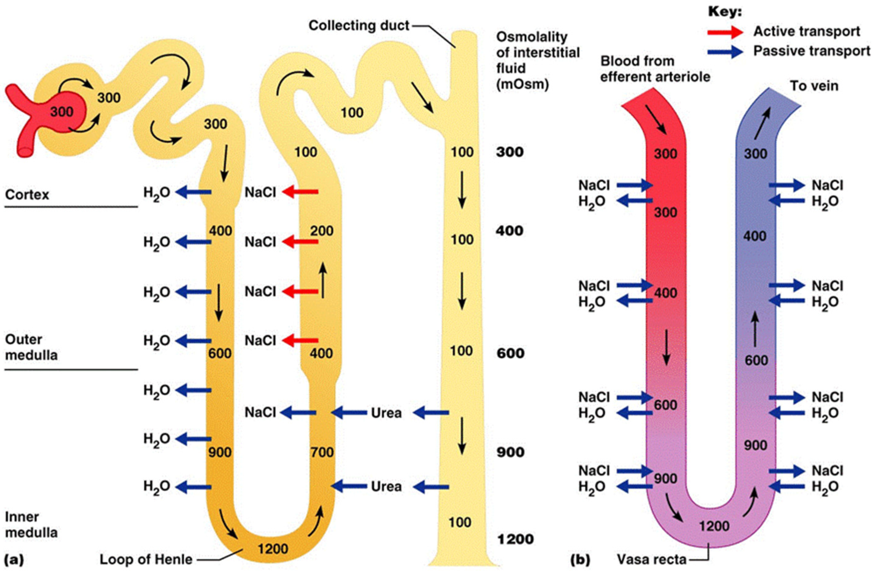
1.3. The Loop of Henle: Physiology and Concept Heat Recovery
A human kidney has three portions: cortex, outer medulla and inner medulla [
25]. The Loop of Henle (
Figure 1) also known as the
ansa nephroni, is a U-shaped portion of the inner medulla. Its unique shape enables urine (which descends downwards before ascending upwards) to increase gradually in concentration, so that substances like water (H
2O) and salt (NaCl) that are still useful to the body can be extracted (
Figure 1a). The U-shaped bottom where urine is most concentrated (
Figure 1b) is called the
Vesa reca and in engineering terms, it is regarded as a counter-current multiplier.
Figure 1.
The Loop of Henle from the human kidney [
25].
Figure 1.
The Loop of Henle from the human kidney [
25].
Based on the natural form of the Loop of Henle and the diffusion of chloride ions (Cl
−) described [
26], a design for a passive heat recovery system was conceived as a Chamber (
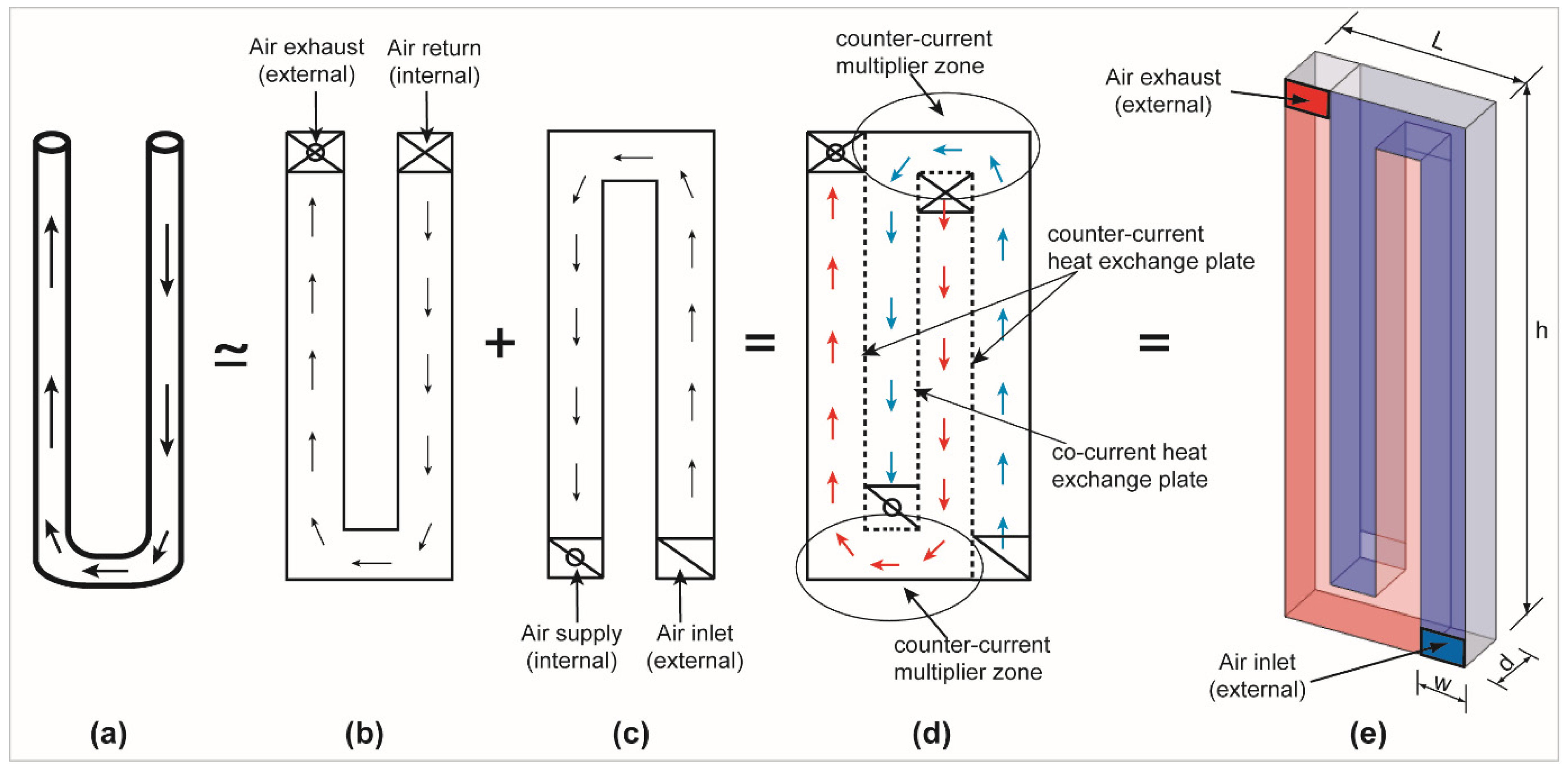
Figure 2) for this research. This Loop of Henle (LoH) Chamber was designed for a single room and metamorphosed through four stages by combining “U” and “∩” loops or airflow channels.
Figure 2.
Schematic evolution of the system showing transition from (a) simple U-shaped loop to (b) a U-shaped flat duct, with (c) an additional inverted duct, (d) merged into (e) the LoH chamber.
Figure 2.
Schematic evolution of the system showing transition from (a) simple U-shaped loop to (b) a U-shaped flat duct, with (c) an additional inverted duct, (d) merged into (e) the LoH chamber.
Starting from a simplified Loop of Henle, the airflow channel is originally of cylindrical cross section (
Figure 2a) but is transformed into a four-sided channel. Buoyant indoor air would be forced (by mass balance) to exit the space from a high-level return vent in the U-shape channel before it is exhausted at another high-level external vent in the same channel (
Figure 2b). Simultaneously, mass balance dictates that cooler outdoor air will be drawn from the low-level external vent of an ∩-shape airflow channel, into the space from another low-level supply point (
Figure 2c). Merging both U-shape and ∩-shape channels will result in a single unit in which both channels are separated by a “Z-shaped” plate. This sheet has three vertical and two horizontal surfaces (
Figure 2d) and would be made of a thin and highly conductive material such as copper or aluminium as used in traditional MVHR systems. The connections of the sheets to the surrounding casing should be impermeable to air. The internal points of air supply and air return are the expected zones/points of counter-current multiplication (
Figure 2d). Two vertical surfaces will experience counter-current flow of air while the third (middle) surface should experience co-current flow of air (
Figure 2d). Overall, the airflow paths of the LoH Chamber design have complied with the segregation (no mixing) of air streams as expected of heat exchangers [
7].
In three dimension, the LoH Chamber is of the same height,
h, as the room in whose walls it will be fitted while its length,
L, width,
w, and depth,
d, can be dictated by performance (airflow rate) requirements (
Figure 2e). Heat exchange is primarily expected to occur across the inner surface (plates) which connect the “U” and “∩” channels. However, the room-side surface of the ∩-shaped supply Chamber is also made of the highly conductive material. This is to encourage the transfer of heat from the warm air in the room to the cooler air in the supply Chamber. Specific dimensions of the LoH Chamber are given in the subsequent section.
Counter-flow heat exchangers (where two streams of air travel in opposite directions) are more efficient than either parallel (co-current) or cross-flow heat exchange process where both streams of air travel in the same direction or at right angles, respectively [
5,
27,
28]. Counter-current multipliers (
Figure 2d) are also useful features of traditional mechanical heat exchangers [
27,
28]. In a counter-current multiplier zone, an elbow in the duct leads to pressure drop, which enhances the heat exchange process between the streams of air.
In summary, the LoH Chamber is basically an air-to-air heat exchange Chamber, whose concept relies on three basic principles: the inverted flow of fluid with counter-current multiplication in the Loop of Henle; the conservation of energy and mass balance in a ventilated space; as well as the buoyant (rising) nature of indoor air being displaced by cooler outdoor air.
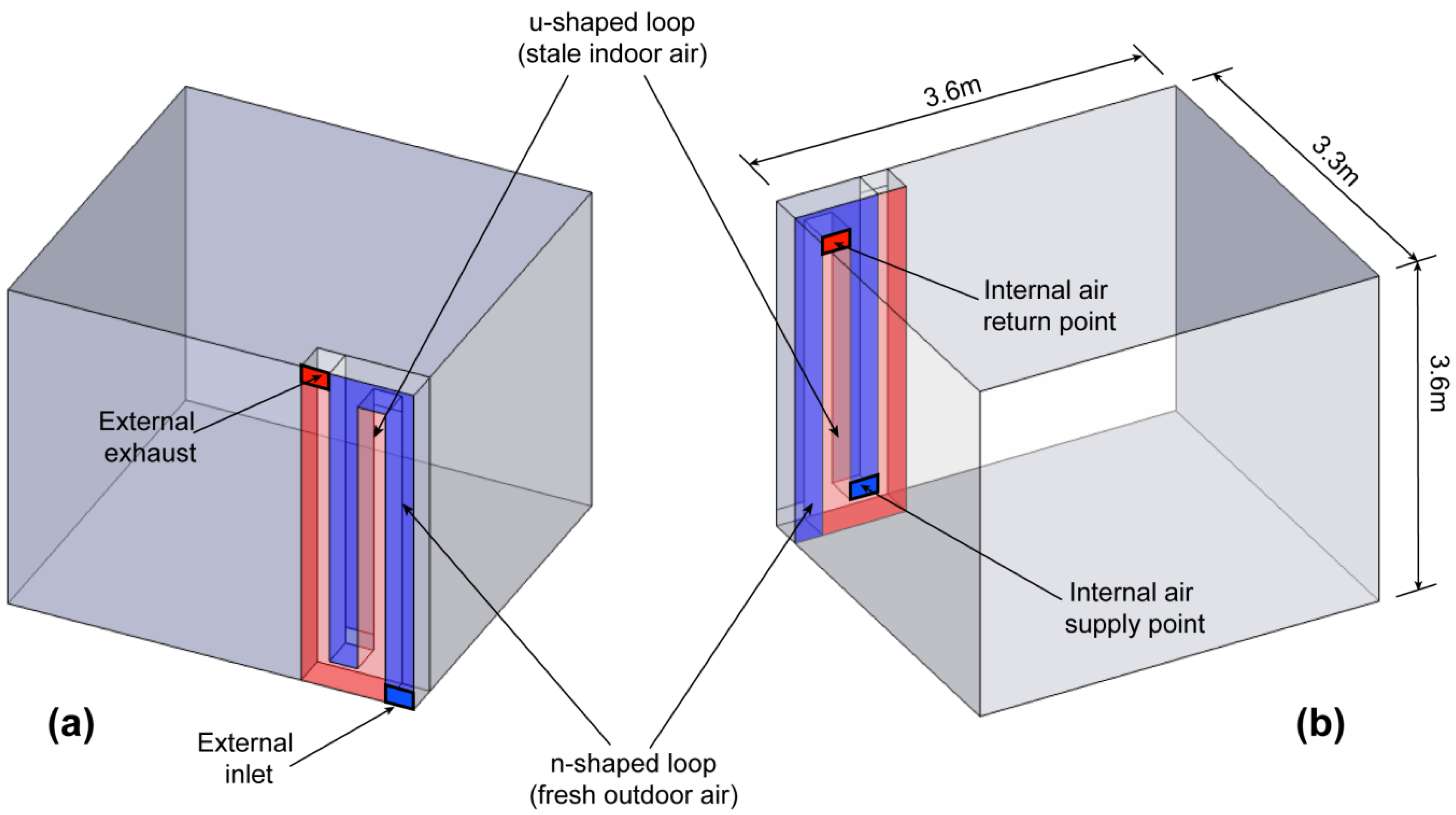
2. Materials and Methods
The LoH Chamber was modelled in 3D and fitted into the corner of a space measuring 3.6 m × 3.3 m (≈12 m
2) and a height of 3.6 m (
Figure 3). Two openings linked the LoH Chamber to the exterior: a low level air intake (inlet) and a high level air outlet (exhaust) while internally, there are corresponding low level supply and high level return openings. The simulation of the LoH Chamber was done through IES, a commercially available software used for dynamic thermal modelling [
29]. The simulation was used to predict the quantitative results for the time-varying performances (e.g., ventilation rates, indoor temperature and CO
2 concentrations) of the LoH Chamber over hours, days, weeks and months.
Figure 3.
The position of simulated LoH Chamber from (a) external view; and (b) internal view.
Figure 3.
The position of simulated LoH Chamber from (a) external view; and (b) internal view.
Many geometric dimensions of the LoH Chamber were considered prior to simulation. The primary deciding factors were: the required area of openings which could deliver up to 1 ACH based on the trickle ventilation rate required to avoid overheating according to CIBSE 2006 [
19]; the cross-sectional area of each loop (
w ×
d); the maximum height,
h, of each loop; as well as the type (and thickness) of heat exchange surface. Aluminium was the material used as the heat exchange surface. Several pilot studies were carried out using looped ducts of various sizes. The size of LoH Chamber reported here has a width of 0.1 m and depth of 0.3 m for each individual channel, resulting in a total facade length,
L, of the entire Chamber being 0.4 m (
Figure 2). The height of the Chamber was equal to floor-to-ceiling height (
i.e., 3.6 m). From pilot study results, these dimensions were regarded as feasible based on criteria of achieving up to 1 ACH [
19] of airflow rates and not less than 10 °C rise in the temperature of preheated fresh air. Additionally, the CIBSE Guide B recommendation [
30] that an indoor CO
2 concentration should be between 800 and 1000 ppm was also taken as a measure of adequate ventilation during the pilot study. Indoor dry resultant temperature of 20 °C will be used as a general reference point for thermal comfort. In addition, the internationalized (ISO), ratings [
31] of predicted mean vote (PMV) model was selected for evaluating the predicted perceptions of thermal comfort, as follows: +3 (hot); +2 (warm); +1 (slightly warm); 0 (neutral); −1 (slightly cool); −2 (cool); and −3 (cold).
In addition to these ventilation metrics/standards used as performance guides, comparisons between the proposed NVHR system and the side-hung windows was made using base case (comparison) simulations. A same-side natural ventilation opening (side hung windows) measuring 1.2 m × 1.2 m was selected for this purpose. Two scenarios were assumed for the base cases: i.e., assuming the window was opened at 25% (one quarter) of its openable fraction and opened at 12.5% (one eighth) of its fraction. The specific assumptions and boundary conditions of the DTM model are described in the next section.
The DTM Models
The geometry of LoH Chamber fitted into the room (
Figure 3) was created in SketchUp [
32] from where dynamic thermal modelling simulation engine (Apache and Macroflo [
29]) was initiated through a plug-in. Five different variations (cases) were considered for the LoH Chamber but three other base cases were also simulated as references. The base cases (Cases 1a, 1b and 1c), were designed as spaces with window openings (
i.e., with reduced opening fractions expected for cold outdoor conditions). These base cases were intended for performance comparison purposes only and Case 1c has an active heating system with 20 °C heating setpoint (
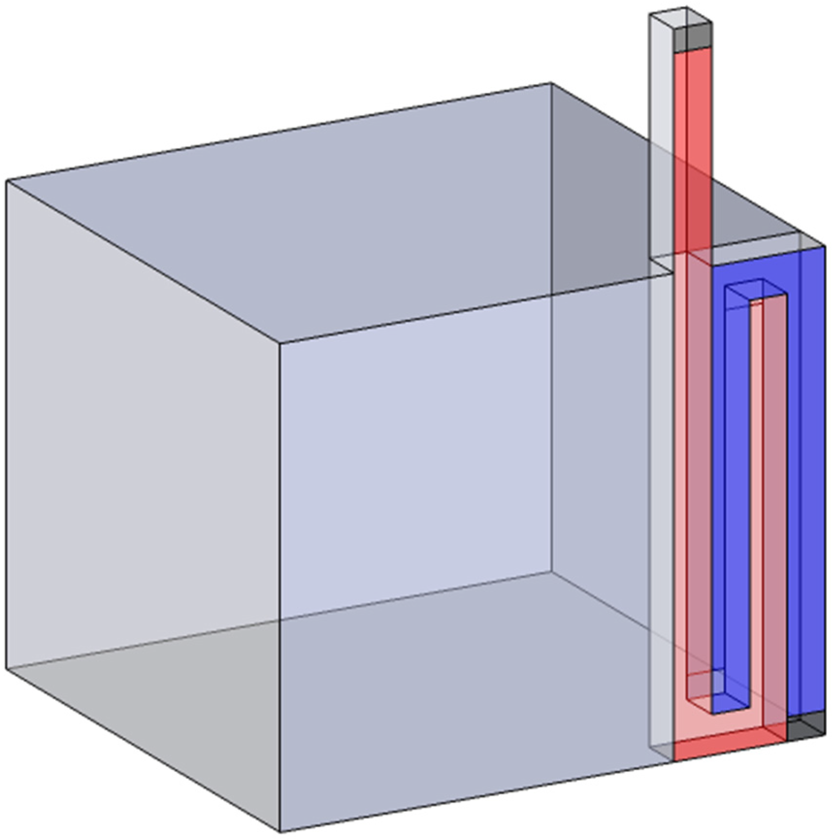
Table 1). The cases which represent the biomimetic NVHR concept (LoH Chamber) are Cases 2a, 2b, and 2c differ in occupancy and presence of active heating. Other NVHR Cases (3a and 3b) have 1.5 m high stacks added to the exhaust of the LoH Chamber, for the purpose of increasing airflow rates through stack effect [
19]. These cases with stacks are also shown in
Table 1. The geometry the LoH Chamber with extended stack is described in
Figure 4.
Table 1.
Description of six cases simulated via dynamic thermal modelling (DTM) application.
Table 1.
Description of six cases simulated via dynamic thermal modelling (DTM) application.
| Cases | Case Description | Active Heating | No. of People | Area of Openings (% Used) | Total IGH (W) | Heat Density (W/m2) |
|---|
| Case 1a | Window at 25% opening | No | 1 | 1.2 × 1.2 m (30%) | 225 | 18.75 |
| Case 1b | Window at 12.5% opening | No | 1 | 1.2 × 1.2 m (15%) | 225 | 18.75 |
| Case 1c | Window at 12.5% opening | Yes | 1 | 1.2 × 1.2 m (10%) | 225 | 18.75 |
| Case 2a | 1 LoH Chamber | No | 1 | 0.1 × 0.3 m (100%) | 225 | 18.75 |
| Case 2b | 1 LoH Chamber | No | 2 | 0.1 × 0.3 m (100%) | 360 | 30.0 |
| Case 2c | 1 LoH Chamber | Yes | 1 | 0.1 × 0.3 m (100%) | 225 | 18.75 |
| Case 3a | 1 LoH Chamber + stack | No | 1 | 0.1 × 0.3 m (100%) | 225 | 18.75 |
| Case 3b | 1 LoH Chamber + stack | Yes | 1 | 0.1 × 0.3 m (100%) | 225 | 18.75 |
Figure 4.
The modified LoH Chamber with extended stack used in Cases 3a and 3b.
Figure 4.
The modified LoH Chamber with extended stack used in Cases 3a and 3b.
For each case, the simulation tool (IES) created by default, three thermal zones: the “U” Chamber; the “∩” Chamber and the occupied space. In all cases, the internally generated heat (IGH) for the occupied space comprised occupant(s) each assigned the IES default values of 74.73 W of sensible heat gain and 70.34 W of latent heat gain making a total of 155 W. Lighting and equipment gains were given assumed values of 20 W and 50 W respectively. Infiltration rate at the default IES value of 0.167 ACH was allowed for each DTM model assuming a modestly tight construction and in compliance with CIBSE Guide A [
19]. The window openings (base cases) were modelled as semi-exposed openings with coefficient of discharge,
Cd, of 0.6 and the effect of wind turbulence was allowed. Nevertheless, airflow through all NVHR openings was presumed to be driven purely by buoyancy via wind-neutral inlets and outlets, since low-velocity flow is desirable in heat exchangers as suggested by the literature previously reviewed [
9,
10]. The heat exchange plate was taken as aluminium 0.01 mm thick with a U-value of 3.846 W/(m
2·K).
The architectural envelope in all cases was modelled to be of high insulation, i.e., U-value of walls was given as 0.003 W/(m2·K). This is because negating heat losses across walls, floors and ceiling was (for the purpose of this study) advantageous in allowing heat exchange through the LoH Chamber to be appreciated. Occupancy was scheduled as 8:00 a.m. to 6:00 p.m. as working hours, with unoccupied lunch being 12:00 p.m. to 1:00 p.m., for all days of the week. Lighting and equipment usage (as well as the active heating systems in Cases 1c, 2c and 3b) followed this schedule too. The geographic location for the DTM was taken as Birmingham, UK.
3. Results and Discussions
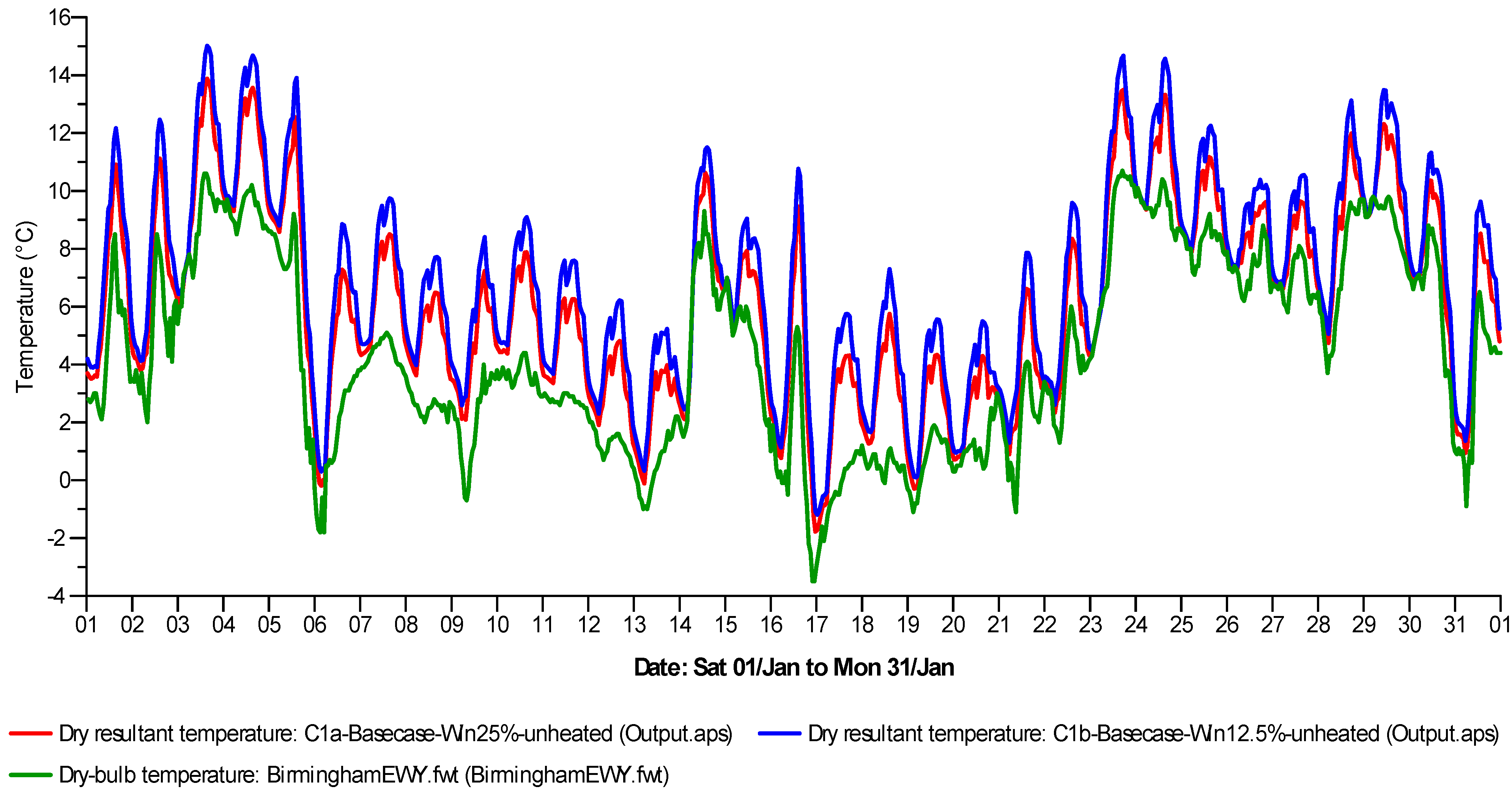
Simulations were carried out for an entire year but results reported and discussed are only for winter months, with emphasis on the mid-winter month of January. For this month, the outdoor dry-bulb temperature for Birmingham would be as low as −3.5 °C and rising no higher than 10.7 °C with a mean weekly dry-bulb temperature of 4.41 °C (
Figure 5). Case 1a (25% opening, unheated space) and Case 1b (12.5% opening, unheated space) would have mean indoor temperatures of 6.24 °C (Case 1a) and 7.02 °C (Case 1b). The maximum indoor temperatures of these cases are 13.88 °C and 15.01 °C respectively. The percentage of monthly hours in which indoor temperatures exceed 10 °C is predicted to be 14.9% for Case 1a and 21.5% for Case 1b. The indoor temperature of these base cases fluctuate in response to the outdoor dry-bulb temperature (DBT) (
Figure 5).
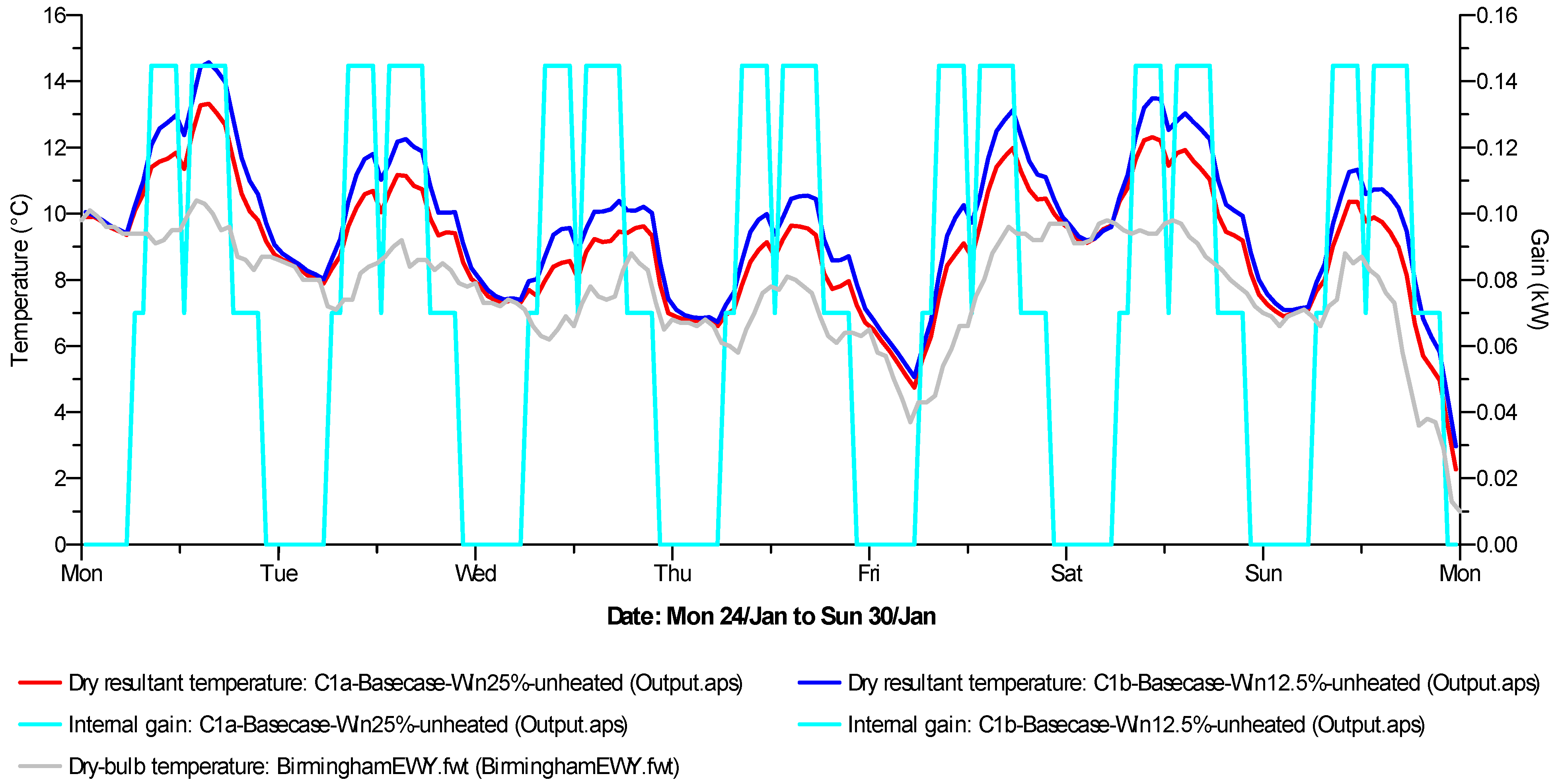
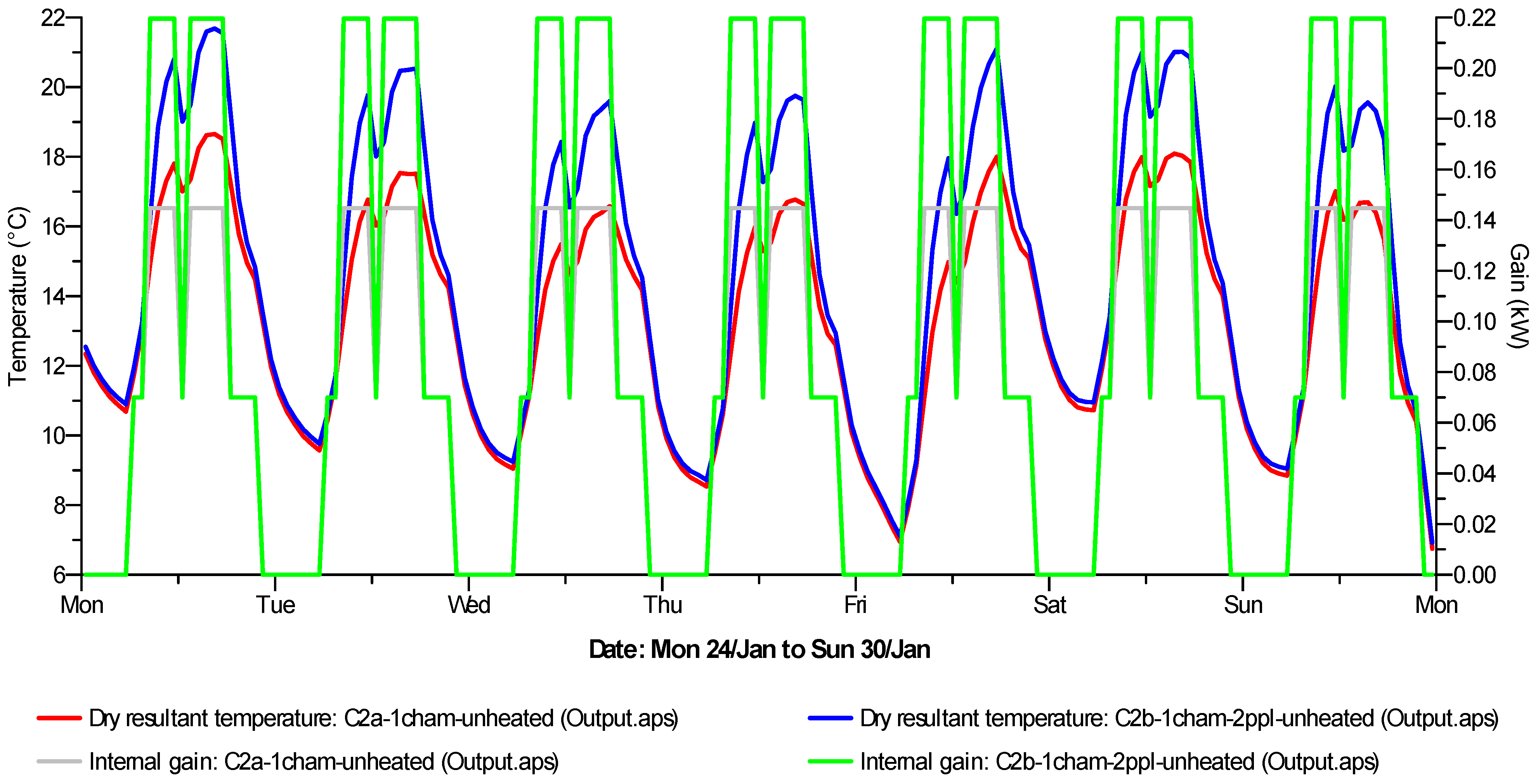
In addition to fluctuations in outdoor temperature (
Figure 5), the internal gains also have strong influence on the pattern of indoor dry resultant temperature (DRT), as shown in Case 1a and Case 1b for a selected week: Monday 24 January to Sunday 30 January (
Figure 6).
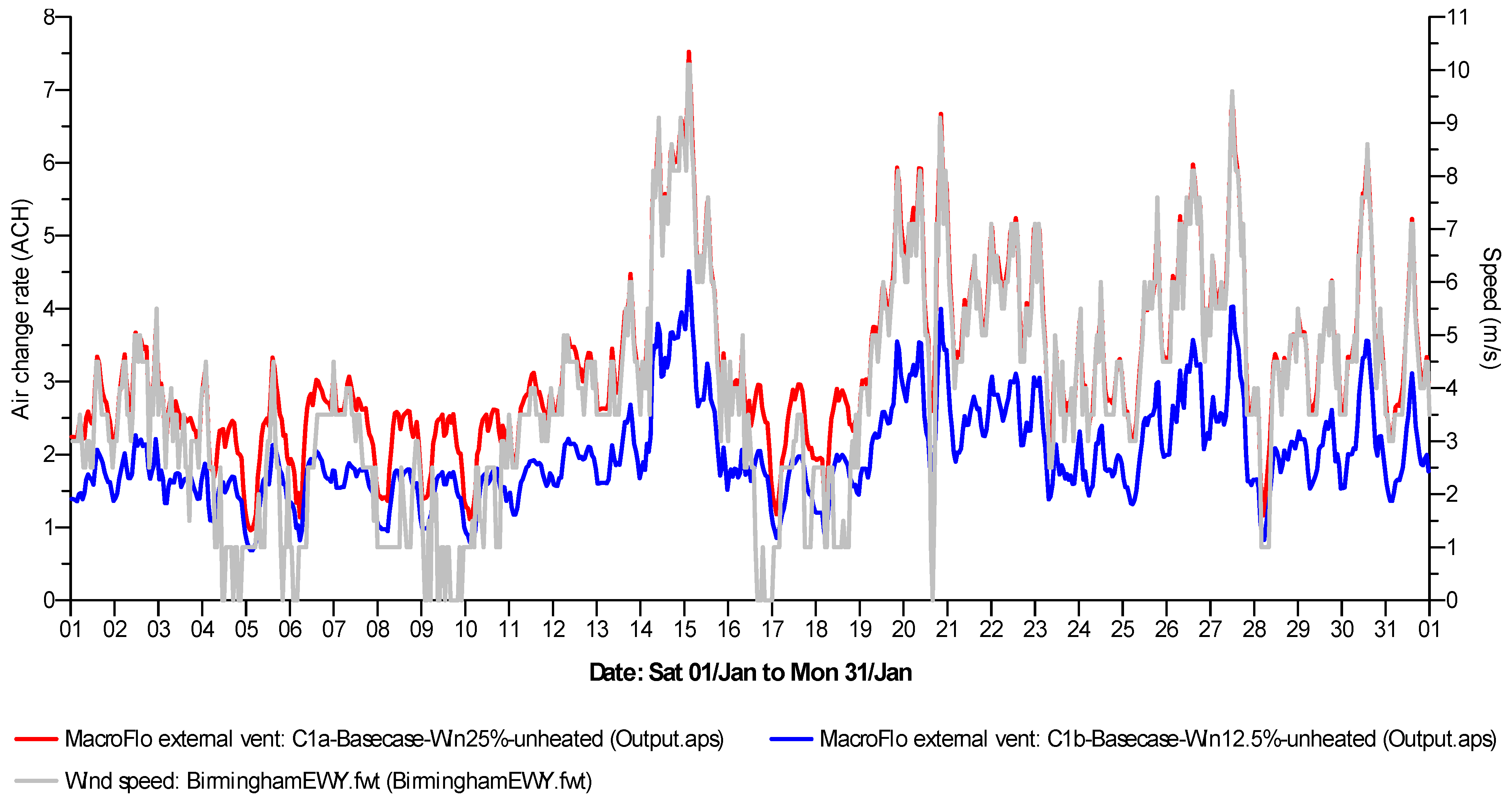
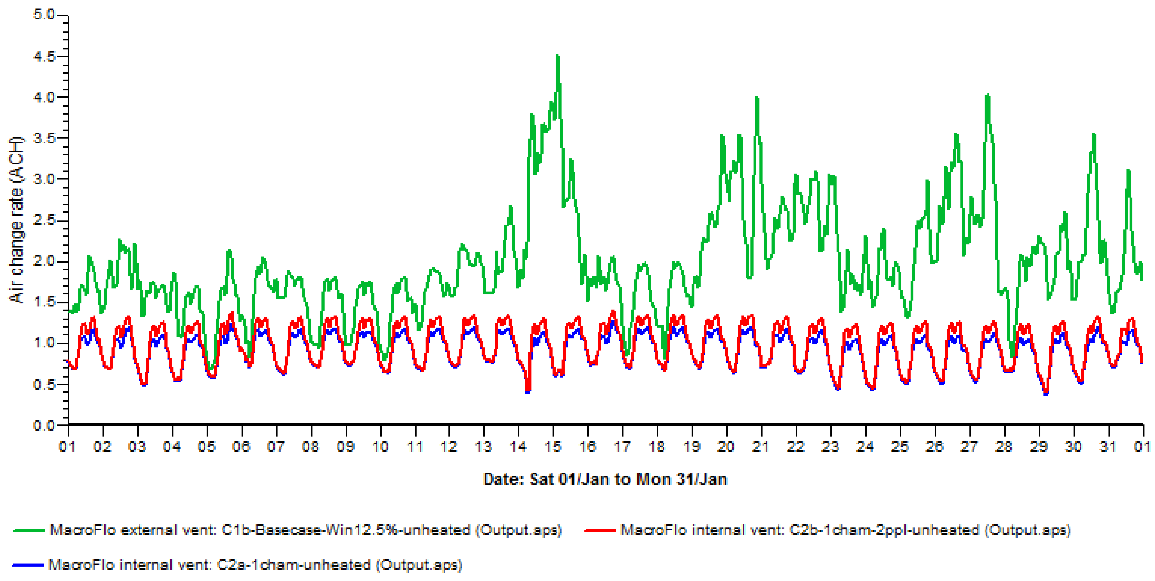
The fluctuations in airflow and the relative ventilation rates achieved by these base cases are primarily determined by wind, whose monthly mean speed is 3.89 m/s (
Figure 7). At 25% opening fraction, the mean airflow into Case 1a is 3.21 ACH and at 12.5% opening fraction, this rate drops to 2.0 ACH. These airflow rates can rise up to maximum values of 7.52 ACH for Case 1a, and up to 4.51 ACH for Case 1b (
Table 2).
Figure 5.
Predicted monthly (January) indoor temperature for unheated base cases.
Figure 5.
Predicted monthly (January) indoor temperature for unheated base cases.
Figure 6.
Predicted (typical January weekly) indoor temperature and internal gains for unheated base cases.
Figure 6.
Predicted (typical January weekly) indoor temperature and internal gains for unheated base cases.
Figure 7.
Predicted monthly airflow rates into the unheated base cases (Cases 1a and 1b).
Figure 7.
Predicted monthly airflow rates into the unheated base cases (Cases 1a and 1b).
Table 2.
Summary of minimum, maximum and mean values for DRT and Airflow rates in Base Cases.
Table 2.
Summary of minimum, maximum and mean values for DRT and Airflow rates in Base Cases.
| Variable | Base Cases | Min. Value | Min. Time and Date | Max. Value | Min. Time and Date | Mean |
|---|
| DRT (°C) | Case 1a: Window 25%-unheated | −1.78 | 23:30, 16 Jan | 13.88 | 15:30, 03 Jan | 6.24 |
| Case 1b: Window 12.5%-unheated | −1.19 | 00:30, 17 Jan | 15.01 | 15:30, 03 Jan | 7.02 |
| AirflowACH (L s−1) | Case 1a: Window 25%-unheated | 0.96 (11.41) | 02:30, 05 Jan | 7.52 (89.44) | 02:30, 15 Jan | 3.21 (38.15) |
| Case 1b: Window 12.5%-unheated | 0.68 (8.14) | 03:30, 05 Jan | 4.51 (53.65) | 02:30, 15 Jan | 2.00 (23.76) |
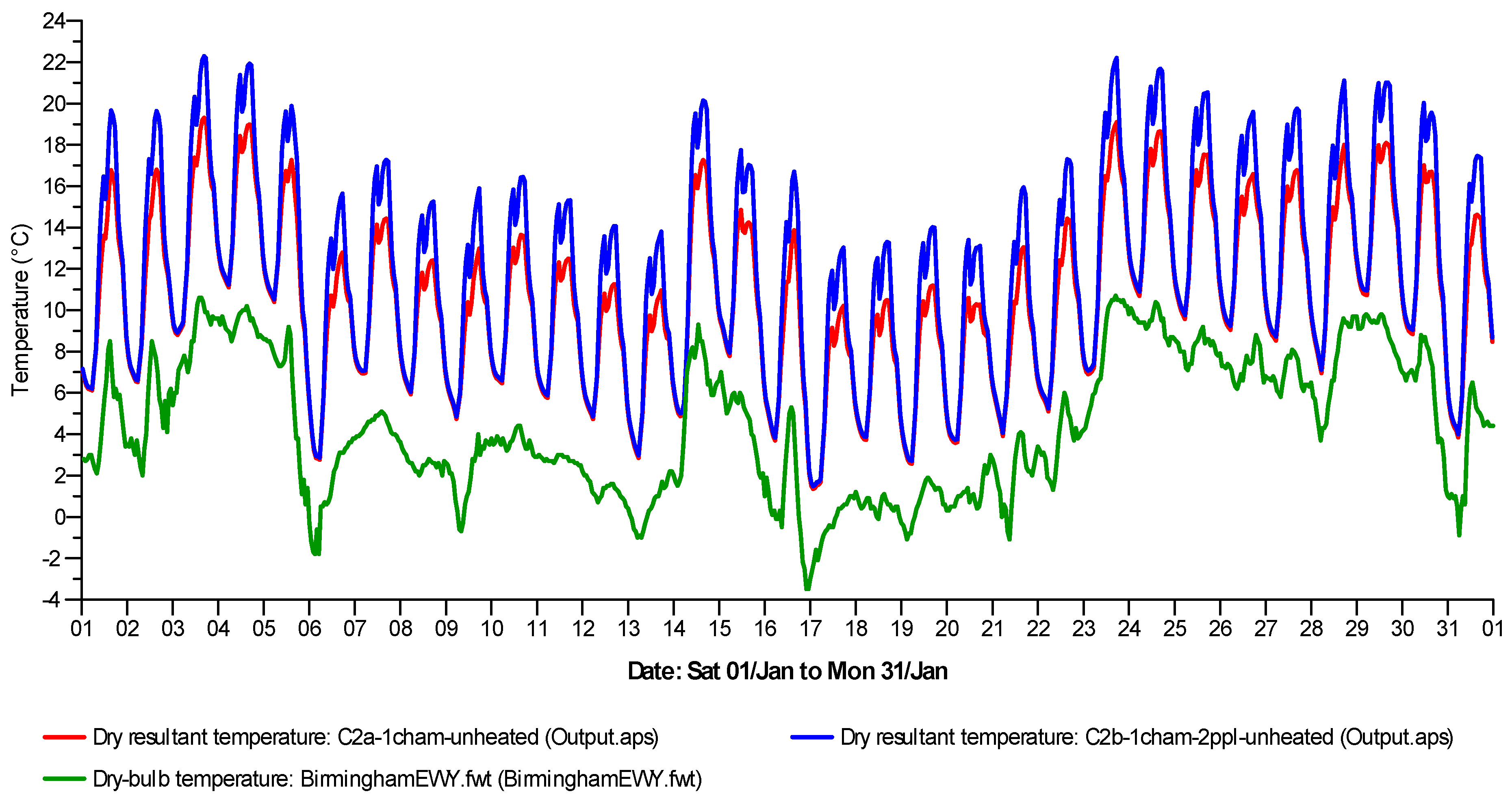
For spaces fitted with the LoH Chamber, having single occupancy (Case 2a) will lead to mean indoor temperatures of 10.7 °C whereas with two people (Case 2b), mean temperatures would be 11.9 °C (
Figure 8). These mean temperature values are generally linked to unoccupied periods, when openings are scheduled to be closed. During occupied periods, the maximum temperatures achievable are estimated to be 19.31 °C (
i.e., one occupant in Case 2a) and 22.29 °C (
i.e., two occupants in Case 2b). However, there are 12 days when indoor temperatures would peak no higher than 16 °C even with two occupants. The role of outdoor temperature in determining these indoor temperatures is also crucial.
The mean airflow rates achievable through the LoH Chamber are: 0.92 ACH and 0.99 ACH for Case 2a (1 occupant) and Case 2b (2 occupants) respectively (
Figure 9). These mean rates are just marginally below the 1 ACH required by CIBSE Guide A [
19] for avoiding overheating. However, the ventilation rates are predicted to rise up to 1.27 ACH and 1.41 ACH for Cases 2a and 2b respectively (
Table 3). These rates would adequately satisfy the CIBSE overheating criteria.
Figure 8.
Predicted DRT for NVHR system in Case 2a and Case 2b.
Figure 8.
Predicted DRT for NVHR system in Case 2a and Case 2b.
Figure 9.
Predicted monthly airflow rates into the unheated NVHR cases (Cases 2a and 2b).
Figure 9.
Predicted monthly airflow rates into the unheated NVHR cases (Cases 2a and 2b).
Table 3.
Summary of predicted values for DRT and Airflow rates in NVHR Cases.
Table 3.
Summary of predicted values for DRT and Airflow rates in NVHR Cases.
| Variable | NVHR Cases | Min. Value | Min. Time and Date | Max. Value | Min. Time and Date | Mean |
|---|
| DRT (°C) | Case 2a: 1 chamber, 1 person, unheated | 1.34 | 01:30, 17 Jan | 19.31 | 16:30, 3 Jan | 10.7 |
| Case 2b: 1 chamber, 2 people, unheated | 1.48 | 01:30, 17 Jan | 22.29 | 16:30, 3 Jan | 11.93 |
| Airflow ACH (L s−1) | Case 2a: 1 chamber, 1 person, unheated | 0.37 (4.25) | 05:30, 29 Jan | 1.27 (14.78) | 17:30, 16 Jan | 0.92 (10.7) |
| Case 2b: 1 chamber, 2 people, unheated | 0.41 (4.72) | 05:30, 29 Jan | 1.41 (16.37) | 17:30, 16 Jan | 0.99 (11.55) |
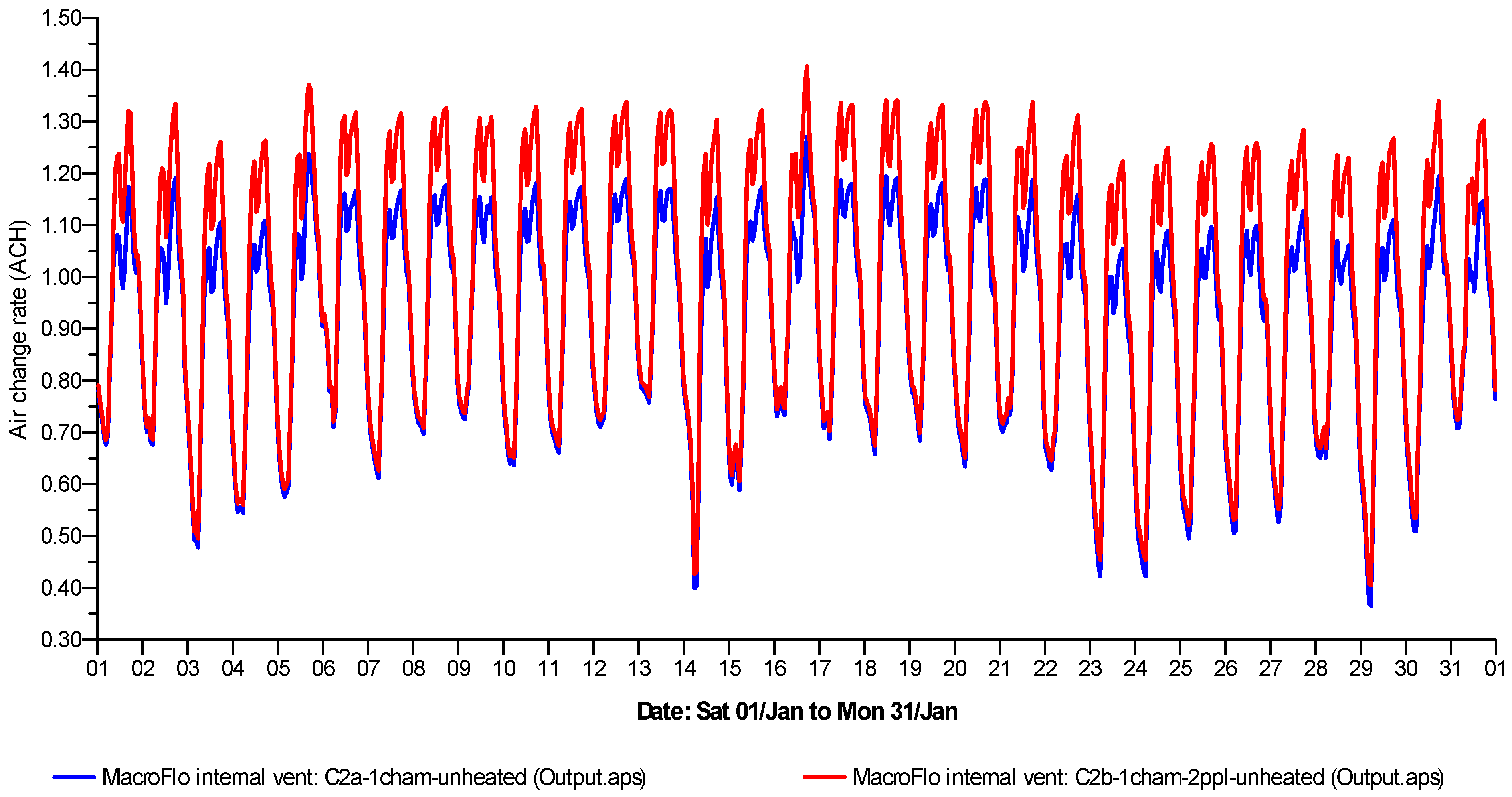
The predicted indoor temperature of Case 1b (Window 12.5% opening) was compared to NVHR Case 2a (1 person, 1 LoH Chamber) and Case 2b (2 people, 1 LoH Chamber). All these case have no active heating and the effect of heat recovery is evident (
Figure 10). For Case 2a with single occupancy, indoor temperatures for January will exceed 10 °C for 56.2% of the time, while with double occupancy; this would increase to 63%. Similarly, a comparison of airflow rates between Case 1b and Cases 2a and 2b (
Figure 11) reveals the steadiness of ventilation in the NVHR system.
Figure 10.
Predicted weekly indoor temperatures and internal heat gains for Cases 2a and 2b.
Figure 10.
Predicted weekly indoor temperatures and internal heat gains for Cases 2a and 2b.
Figure 11.
Intermittent ventilation in Case 1b compared to more steady rates in NVHR Cases 2a and 2b.
Figure 11.
Intermittent ventilation in Case 1b compared to more steady rates in NVHR Cases 2a and 2b.
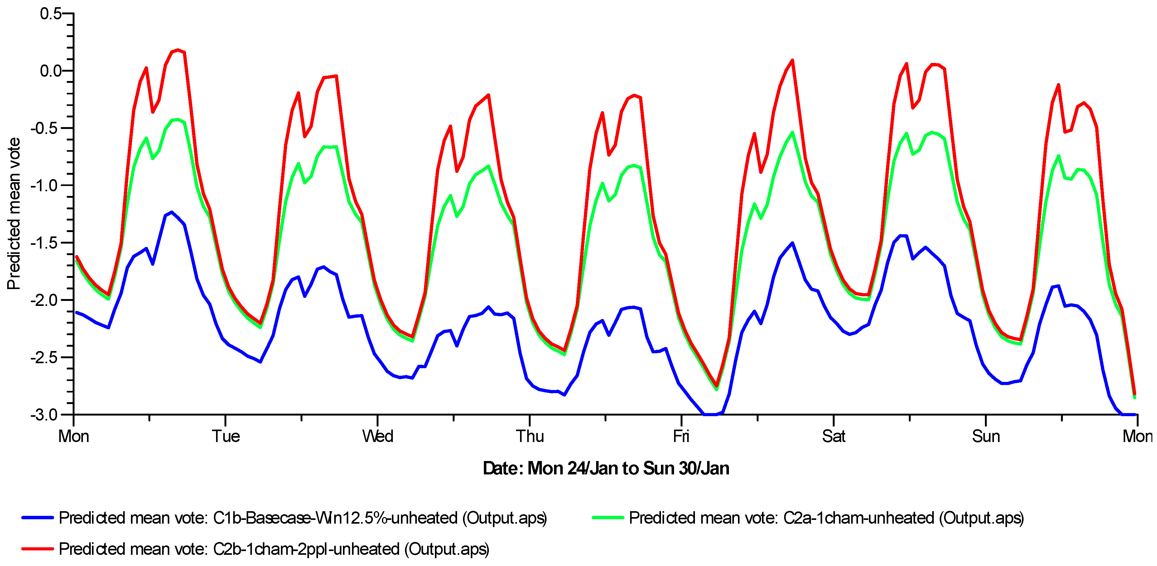
For the selected January week, the predicted results for PMV and indoor CO
2 concentration are also instructive. The PMV for Case 2b (NVHR with two occupants) is much better,
i.e., approaches the neutral “0” thermal comfort benchmark of zero (
Figure 12) compared to Case 2a which approaches the slightly cool “−0.5” mark. The window case would regularly have PMV values below “−1.5” and for two days, the PMV will be around or below “−2.0” mark.
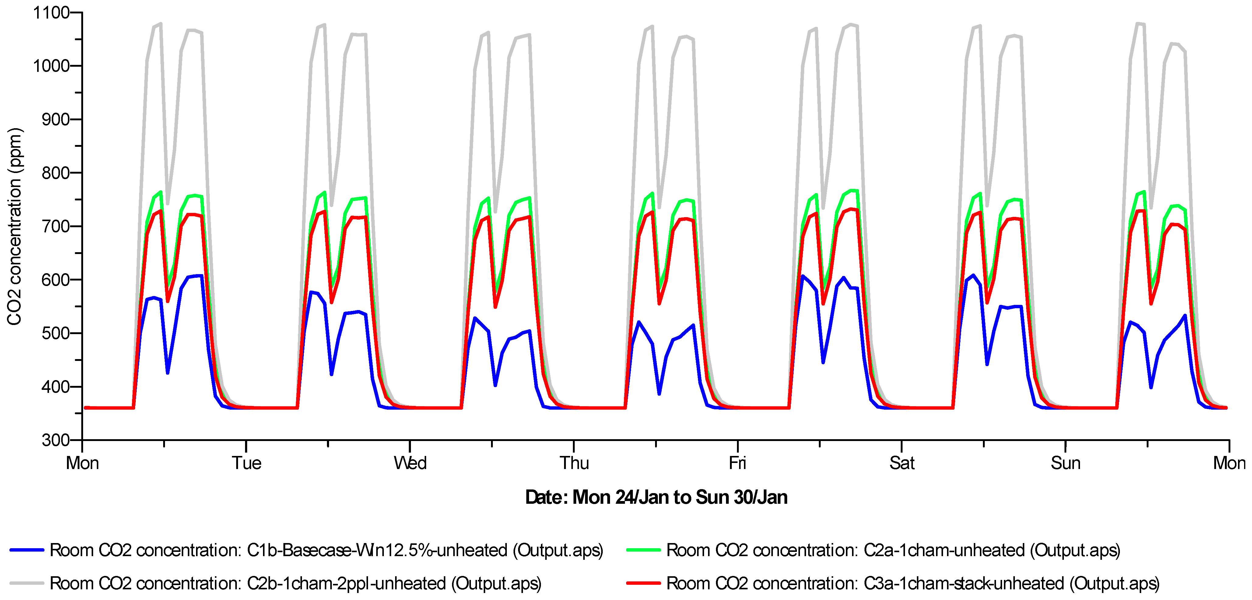
For the NVHR cases, the daily indoor CO
2 concentration with double occupancy exceeds 1000 ppm but with a single occupant the concentration remains below 800 ppm (
Figure 13). When the LoH Chamber’s exhaust point is extended by a stack (Case 3a), the expected increase in airflow rates ensure that daily indoor CO
2 concentration fall to around 700 ppm.
Figure 12.
Predicted Mean Votes for Case 1b and Cases 2a and 2b.
Figure 12.
Predicted Mean Votes for Case 1b and Cases 2a and 2b.
Figure 13.
Concentration of carbon dioxide in Cases 1b, 2a, 2b and 3a.
Figure 13.
Concentration of carbon dioxide in Cases 1b, 2a, 2b and 3a.
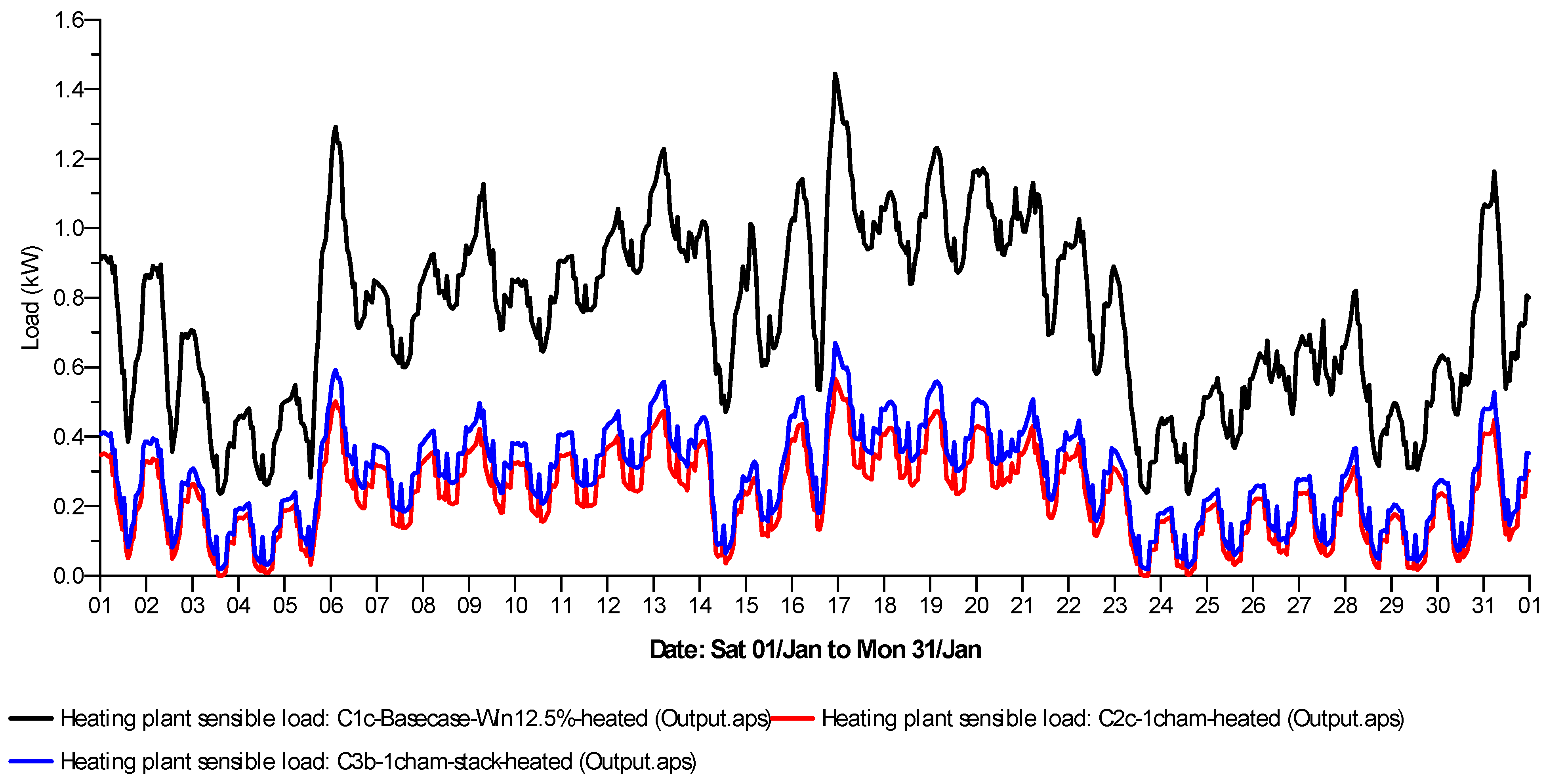
There are significant differences in power required to heat the spaces (
Figure 14). Three cases where active heating was used are compared: Case 1c (window at 12.5% opening fraction); Case 2c (NVHR with one occupant) and Case 3b (stacked NVHR with one occupant). For all cases, heating power would peak on 16 January with up to 1.445 kW for Case 1c and a maximum of 0.566 kW for the NVHR Case 2c.
Figure 14.
Power required for active space heating in Cases 1c, 2c and 3c.
Figure 14.
Power required for active space heating in Cases 1c, 2c and 3c.
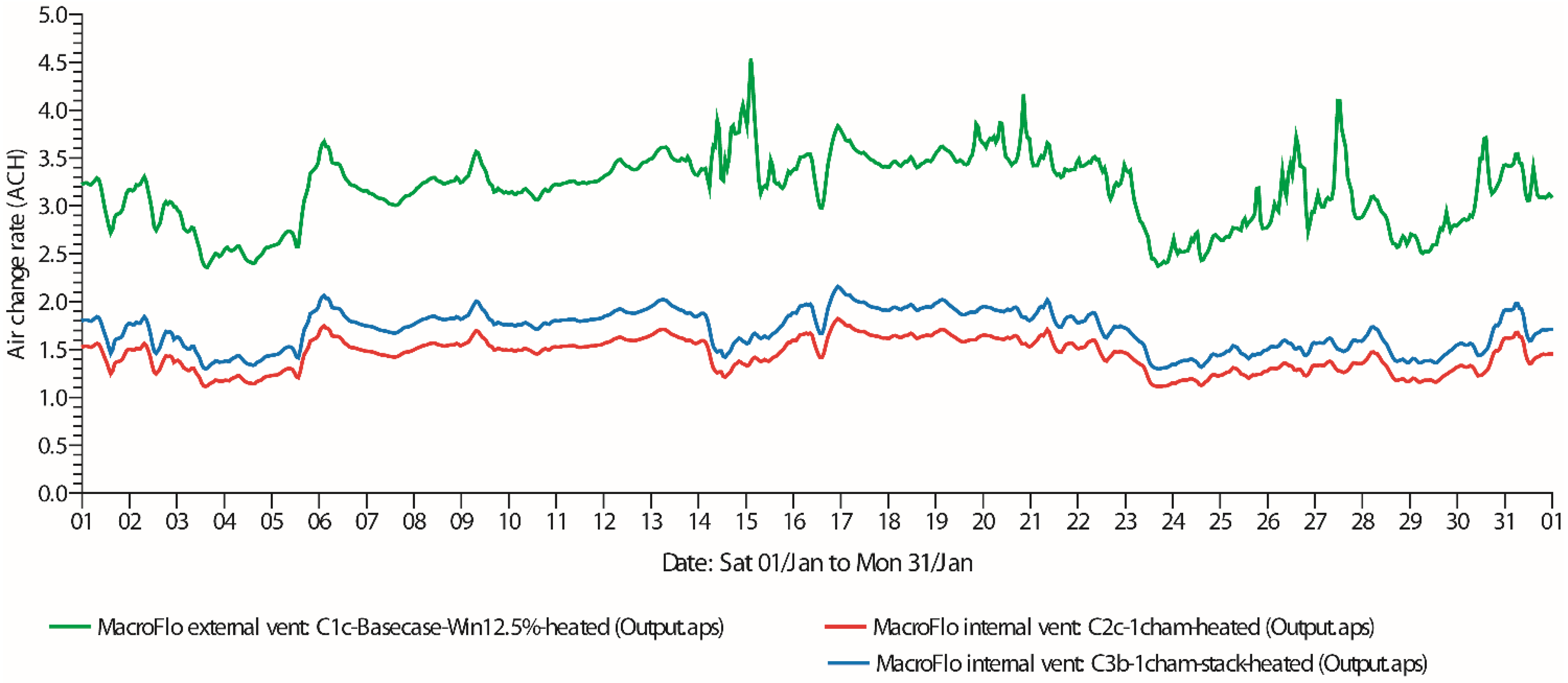
With an extended stack (NVHR Case 3b), heating power would be 0.669 kW. The relative increment in heating power required by the extended stack over the entire month is notable. This stack will help reduce indoor CO
2 concentrations, e.g., from a maximum of 767 ppm to 732 ppm (
Figure 13). The reduction is due to increased airflow rates, whose monthly average exceeds 1.5 ACH (
Figure 15).
Figure 15.
Predicted ventilation rates for heated base case (Case 1c) and heated NVHR Cases 2c and 3b.
Figure 15.
Predicted ventilation rates for heated base case (Case 1c) and heated NVHR Cases 2c and 3b.
Assuming active heating is required at 20 °C heating setpoint, the predicted total annual energy (MWh) required for base Case 1c (window at 12.5% opening) is 4.064 MWh. The monthly heating energy required for each of these cases is summarized in
Table 4 where the reduced heating energy required for Case 2c and Case 3c can be appreciated relative to Case 1c.
In evaluating the implications of the predicted DRT and PMV results derived from this study, consideration should be given for adaptive thermal comfort. As defined and argued by de Dear and Brager [
33], individuals are likely to react to their thermal environment by adapting to it, e.g., by adjusting their clothing. This hypothesis, according to Nicol [
34] attempts to satisfy some of the shortcomings of the heat balance method, e.g., Fanger’s model [
35]. In other words, adaptive thermal comfort could explain why in naturally ventilated buildings, people are able to declare their satisfaction with (or tolerance of) temperatures that would otherwise be classified as uncomfortable using heat balance model. The adaptive thermal comfort model has hence been used in the UK [
36,
37,
38] as a yardstick for estimating energy consumption of buildings based on occupant perception of their thermal environment. In other words, the potentials of the LoH Chamber should be appraised in light of the possibilities which adaptive thermal comfort offers.
Table 4.
Heating plant sensible load.
Table 4.
Heating plant sensible load.
| Month | Case 1c (MWh) | Case 2c (MWh) | Case 3b (MWh) |
|---|
| January | 0.559 | 0.173 | 0.212 |
| February | 0.540 | 0.158 | 0.194 |
| March | 0.502 | 0.152 | 0.187 |
| April | 0.448 | 0.121 | 0.150 |
| May | 0.258 | 0.061 | 0.075 |
| June | 0.122 | 0.030 | 0.037 |
| July | 0.101 | 0.024 | 0.029 |
| August | 0.095 | 0.021 | 0.026 |
| September | 0.150 | 0.034 | 0.042 |
| October | 0.283 | 0.074 | 0.092 |
| November | 0.481 | 0.134 | 0.166 |
| December | 0.527 | 0.150 | 0.185 |
| Annual Total | 4.064 | 1.132 | 1.394 |
| Difference with Case 1c | - | 2.931 (72.1% of Case 1c) | 2.670 (65.7% of Case 1c) |
4. Conclusions
This research has investigated the conceptual feasibility of a biomimetic system of natural ventilation with heat recovery (NVHR). The study was inspired by the need to develop a passive heat exchange system that can be embedded within the fabric/envelope system of new buildings. The source of energy for pre-heating fresh air in this system is from miscellaneous indoor sources: occupants, equipment/devices and artificial lighting systems. These sources provide the heat that is reusable through the LoH Chamber, whose 100 mm wide ducts were able to achieve mean relative ventilation rates of around 0.9 ACH. This mean ventilation rate is just slightly short of the 1.0 ACH required to avoid overheating, while the maximum rate possible with the system varies between 1.27 ACH and 1.41 ACH—depending on single or double occupancy respectively. For this wind-neutral system, temperature differential (determined by low external winter temperatures and internal heat gains) is the primary driving force for ventilation.
When active heating was added to the room fitted with the LoH Chamber, heating energy was found to be between 65.7% and 72.1% lower than in a window-ventilated room without a heat exchanger. The predicted differences in energy consumption obtained depend on whether a stack (i.e., an elevated exhaust point) is used to increase airflow rates through the LoH Chamber. The enhanced airflow through the stack helped reduce the indoor CO2 concentration with approximately 1.5 ACH. However, thermal comfort based on predicted DRT and PMV was improved only when internal heat loads are increased (double occupancy).
The supply of fresh pre-heated air through this system is advantageous because modest ventilation rates can be met with reduced dependence on active heating devices. The LoH Chamber in its present form would not independently satisfy thermal comfort needs based on predicted heat loads, but adaptive thermal comfort suggests it has potential. In the simulations carried out, it is not immediately apparent to what extent the use of conductive surface on the room-side surface of the supply (n-shape) loop has aided the transfer of heat transfer from the warm air in the room to the cooler air in the supply loop. It is probable though that heat transfer across this surface is minimal, but only detailed modelling (e.g., CFD) and experiments can provide more insight on this aspect. The performance of the LoH Chamber can be expected to be much better if copper were used as the heat exchange plate. This alternative material is a candidate for future research exploration. The resulting LoH Chamber which was optimised to a width 0.4 m has potential to operate as a stand-alone cabinet. This could make it suitable for retrofitting in multi-floor apartments, in old/listed buildings or in existing facilities such as hospitals where complex ducting from MVHR in wards would neither be ideal nor practical.
5. Limitations and Future Work
The results are not without their limitations. Only single zone spaces (rooms) were modelled whereas in reality, e.g., with multiple zones or several rooms in whole buildings, the opening and closing of doors would affect the airflow regime, pressure boundaries and hence system performance. This is a factor to be considered when appraising the predicted results. In addition to modelling the system under multi-zone (i.e., well-mixed) conditions, DTM results offer time-varying predictions but steady-state or transient CFD simulations are required for qualitative (space-varying) estimates. However, simulating infiltration e.g., through crack flow equations in CFD will be computationally expensive. Therefore, full scale experiments are required (and planned) for detailed investigations.
The experimental phase of research will use both aluminium and copper sheets of suitable thickness and width. Limitations in width of commercially available thin copper sheets are likely to influence a 1:2 scale model (1.8 m × 1.5 m × 1.8 m) using scheduled artificial heat sources. Subsequent modelling work targeting optimisation of the system will include: the use of fins to aid heat exchange along the plates; the use of corrugation (instead of flat sheets of metal) to increase the contact surfaces of the heat exchange plates; as well as the use of advanced polymer-based membranes or 45-gsm Kraft paper as used by Nasif
et al. [
23] as heat exchange surfaces. Further optimisation of the system design and material specifications is therefore possible.
The geometric compaction of the LoH Chamber probably gives it as much if not more potential as a stand-alone cabinet as a wall-embedded system for new buildings. Due to total segregation of air streams, it is also plausible to consider the use of the LoH Chamber for collecting waste heat in or around a building. For example, waste heat in kitchens and boiler rooms could be collected by the LoH Chamber in order to pre-warm the air that is fed into MVHR systems for a hybrid set-up. Additionally, since mixing of incoming and outgoing air does not occur, the quality of incoming air will presumably be devoid of any contaminant generated indoors. Hence, for clinical spaces (e.g., hospital wards) this principle of segregating incoming from outgoing air [
39] could make the LoH Chamber feasible for further studies and application in hospitals. The decentralized nature of its design means disruption of hospital activities during retrofitting, which can then be done on a ward by ward basis.


