Article

Adaptive Shell Spherical Reflector Actuated with PVDF-TrFE Thin Film Strain Actuators

1
Department of Control Engineering and System Analysis, Université Libre de Bruxelles (ULB), CP. 165-55, 50 Av. F.D. Roosevelt, B-1050 Brussels, Belgium
2
Materia Nova Research Center, 3 Av. Nicolas Copernic, B-7000 Mons, Belgium
*
Author to whom correspondence should be addressed.
Actuators 2021, 10(1), 7; https://doi.org/10.3390/act10010007
Submission received: 15 December 2020 / Revised: 24 December 2020 / Accepted: 26 December 2020 / Published: 30 December 2020
(This article belongs to the Special Issue Feature Papers to Celebrate the SCIE Coverage)

Abstract

:
This paper discusses the design and manufacturing of a thin polymer spherical adaptive reflector of diameter D = 200 mm, controlled by an array of 25 independent electrodes arranged in a keystone configuration actuating a thin film of PVDF-TrFE in d 31 -mode. The 5 μ m layer of electrostrictive material is spray-coated. The results of the present study confirm that the active material can be modelled by a unidirectional quadratic model and that excellent properties can be achieved if the material is properly annealed. The experimental influence functions of the control electrodes are determined by a quasi-static harmonic technique; they are in good agreement with the numerical simulations and their better circular symmetry indicates a clear improvement in the manufacturing process, as compared to a previous study. The low order optical modes can be reconstructed by combining the 25 influence functions; a regularization technique is used to alleviate the ill-conditioning of the Jacobian and allow to approximate the optical modes with reasonable voltages.

1. Introduction

Large aperture deployable spherical reflectors have for long been identified as necessary for the future of telecommunication and monitoring the Earth environment [1,2]. This brings numerous challenges associated with the launch: volume and weight constraints, harsh vibratory environment, and the in-orbit operation: deployment, surface figure accuracy after deployment, under thermal gradients and gravity gradients. Concepts with low areal density (<3 kg/m 2 ) and high stowability are of particular interest. Lenticular, pressure stiffened membranes are discussed in Reference [3]; inflatable space antennas are prone to gas leakage due to micrometeorites, which hinders the application of long duration missions; besides, their wavefront error tends to be dominated by the spherical aberration [4]. Doubly curved, form stiffened elastic shells are explored in References [5,6]; the reflector unfolds on its own strain energy once released to form its final shape. A combination of a proven lightweight deployable mesh antenna with a high precision polymer membrane reflector is considered in Reference [7]; the membrane is controlled actively by a set of electrostatic actuators.
In all cases, a high figure accuracy will require some sort of active shape control. This can be realized in various methods depending on the configurations: with a group of thermal actuators for a truss antenna [8], with electrostatic actuators (acting out of plane) on a mesh supported antenna [7] or with an array of piezoelectric orthotropic actuators (acting in plane) glued on the back of the reflector [9]. The present work is a follow-up to Reference [10]; it is concerned with adding a thin film of electrostrictive copolymer material (PVDF-TrFE) on a polymer spherical shell substrate; an array of independent electrodes form a set of strain actuators (acting in plane). Two ways of application of copolymer have been investigated—spin-coating and spray-coating. PVDF-TrFE is electrostrictive and behaves quadratically; it is isotropic and, with an appropriate bias electric field, it allows to achieve an excellent piezoelectric constant up to d 31 15 pC/N.
Strain actuators are very efficient for to deform flat plate structures and deformable mirrors with active layers of piezoelectric actuators are widely used in Adaptive Optics (AO), for example, Reference [11]. However, the study on the strain actuation of an ultra-thin spherical shell shows the morphing behavior is very different from that of a flat plate, because the rigidity of a spherical shell depends very much on the mode of solicitation (achieving a defocus with a given amplitude will be much more difficult than astigmatism). Besides, the accurate shape control with an array of independent electrodes requires that the electrode size ϱ (estimated by ϱ = 4 A / L c , A is the electrode area and L C is the perimeter of the electrode profile) be such that
ϱ < ( R c t ) 1 / 2 ,
where R c is the radius of curvature and t is the thickness of the shell [12,13]. Significant departure from the condition of Equation (1) will lead to a steep and wavy transition of the deformed shape between electrodes excited with different actuating strains (i.e., different voltages in the case of electrostrictive materials). According to the foregoing constraints, an adaptive reflector of diameter D = 10 m with a radius of curvature of R c = 200 m and a thickness of t = 175 μ m would require more than 2000 independent electrodes, and the same reflector with R c = 20 m requires 10 times more. Controlling the shape of structures with such a large number of actuators will require a sophisticated metrology and special control algorithms, because of the ill-conditioning of the Jacobian of the system [13,14].
This paper reports on a small-scale technology demonstration project called “Multilayer Adaptive Thin Shell Reflectors for Future Space Telescopes” (MATS) developed on behalf of European Space Agency (ESA) in the framework of the General Support Technology Programme (GSTP) program. Preliminary results were published in Reference [10], with a demonstrator of diameter D = 100 mm, spin-coated, controlled with 7 independent electrodes. The present paper considers a reflector of D = 200 mm controlled with 25 independent electrodes. The PVDF-TrFE is spray-coated rather than spin-coated in the smaller one, because it is more representative of what can be used on a large reflector. Numerical simulations have been reported in Reference [15]; the present paper reports on the experiments; it is organized as follows—Section 2 recalls the basic equations describing the behavior of an electrostrictive material and summarizes the methods used in Reference [10] to determine the main material properties of PVDF-TrFE thin films. Section 3 discusses the manufacture of the demonstrator. Section 4 reports experimental results on control authority, showing the various influence functions of individual electrodes; they can be combined to approximate low order optical modes. Section 5 concludes the paper.

2. Electrostrictive Materials

2.1. Material Model

In the previous part of this study [10], it was found that the behavior of the thin film of PVDF-TrFE can be accounted for with a linear dielectric model:
D 3 = P s + ε 1 E 3
and the quadratic unidirectional material model:
S 3 = Q 33 D 3 2 = Q 33 P s 2 + 2 ε 1 P s Q 33 E 3 + ε 1 2 Q 33 E 3 2 .
In these equations, D 3 is the electric displacement, P s is the remnant (spontaneous) polarization, ε 1 = ε 0 ε r is the dielectric constant ( ε 0 = 8.85 × 10 12 F/m) and E 3 the electric field. S 3 is the strain along the polarization direction and Q 33 is the electrostrictive coefficient. Q 33 P s 2 is the poling strain which takes place during the polarization. Q 33 and P s are material properties that must be determined experimentally. The strain in the poling direction induces isotropic in-plane strains according to
S 1 = ν S 3 = ν ( Q 33 P s 2 + 2 ε 1 P s Q 33 E 3 + ε 1 2 Q 33 E 3 2 ) ,
where ν is the Poisson’s ratio. It follows that the piezoelectric coefficient d 31 is given by
d 31 = S 1 E 3 = 2 ν ( ε 1 P s Q 33 + ε 1 2 Q 33 E 3 ) .
This equation indicates that a bias electric field increases the piezoelectric coefficient. Thus, any (electrostrictive) material can be made piezoelectric by applying a bias electric field [16]. From the foregoing equation,
d ( d 31 ) d E 3 = 2 ν ε 1 2 Q 33 .

2.2. Material Properties

The method for determining the material properties ( ε 1 , d 31 , Q 33 , P s ) has been described extensively in Reference [10] for the spin-coated film. In the present study, it was decided to substitute the spin-coating of the PVDF-TrFE by spray-coating which can be easily scaled-up to reflectors of large size. The dielectric constant ε 1 was obtained from capacitance measurements; the piezoelectric constant d 31 was obtained for various bias electric field E 3 from modal analysis on small cantilever beams (Figure 1). The electrostrictive constant Q 33 was deduced from the slope of the curve d 31 ( E 3 ) according to Equation (6). Typical values obtained on small samples are given in Table 1.
The remnant polarization was obtained in two different ways: (i) From Equation (5) after determining d 31 and Q 33 and (ii) from the analysis of the structural response to a quasi-static harmonic excitation E 3 = E B + E 0 cos ( 2 π f 0 t ) . Because of the quadratic behavior of the electrostrictive material, the structural response exhibits contributions at the excitation frequency f 0 and also at the harmonic 2 f 0 . P s can be deduced from the relative amplitudes of these contributions [10]. The two methods lead to consistent results as one can see in the last two lines of Table 1. Surprisingly, the values of the dielectric constant ε r have been found consistently smaller for the spray coated samples than for the spin coated ones.
According to Equation (4), once Q 33 and P s are known, the poling strain is given by
S p = ν Q 33 P s 2 .
In Reference [10], a direct measurement was obtained by monitoring during the poling process the curvature of a thin sample of glass covered by PVDF-TrFE and comparing with a finite element simulation; the experiment led to a value of S p consistent with Equation (7).

3. Manufacturing of the Demonstrator

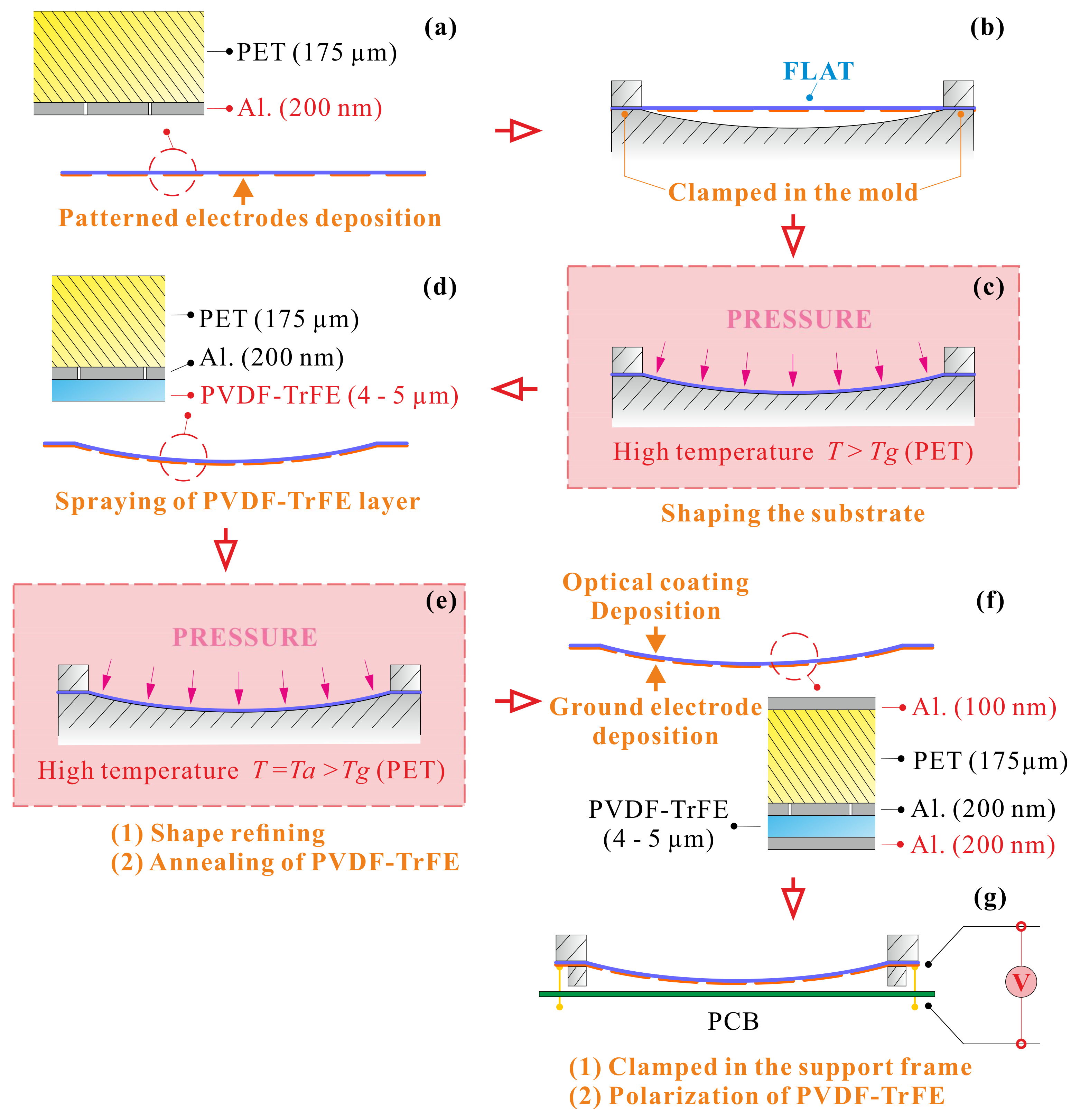
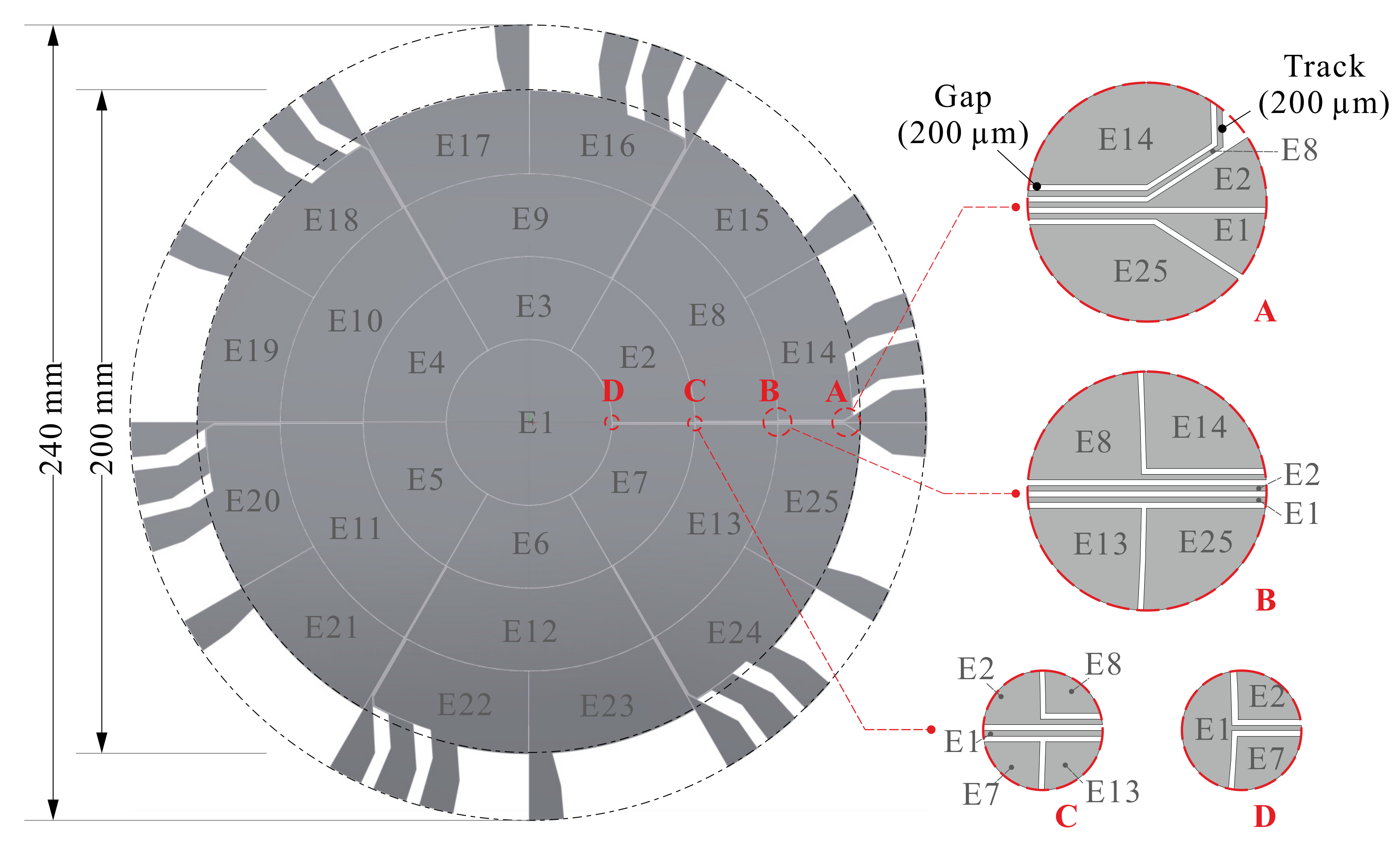
The flowchart of the manufacturing of the demonstrator and the stacking sequence are shown in Figure 2. The starting point is a flat amorphous PET film with a thickness of 175 μ m. The PET film is a commercial product (Luminor 4001) with a low roughness ( R a = 9 nm; R z = 220 nm) which guarantees a good reflectivity of the mirror; it is also free of topcoat (acrylic) which induces significant stresses during the subsequent annealing process. The glass transition temperature and the melting temperature are respectively T g = 85.4 °C and T f = 263 °C. A 200 nm Aluminum (Al) layer of patterned electrode is deposited by Pulse DC Magnetron Sputtering (PDCMS). Figure 3 shows the keystone layout of the electrodes and the tracks allowing to place all the electrical connections on the edge of the reflector; the mask is obtained by lithography; all electrical connections have a width of 200 μ m with gaps of 200 μ m. After numerical simulations of the control performances, the radially uniform electrode size was selected.
The second step is the shaping of the reflector; it is achieved by placing the PET substrate in a spherical mold with a radius of curvature R c = 2.5 m (Figure 2b), heating to a temperature of 140 °C during 2 h with an external pressure of 2 bars, and cooling to room temperature before demolding. The next step (Figure 2d) consists of spray coating the film of PVDF-TrFE of 4–5 μ m (coating by spray is preferred to spin coating because it can be easily scaled-up to large areas). The electrostrictive copolymer is the PVDF-TrFE FC25 of Piezotech, already used with spin coating in the previous study [10]; however, in order to maximize the thickness homogeneity when applied by spray, the copolymer concentration and the solvent mixture (MEK-MIBK) had to be re-optimized; a solution of 6 g/L in MEK-MIBK 75:25 was adopted. Annealing is performed by placing again the reflector in the mold (Figure 2e); it is essential to develop the β -phase which is piezoelectric. Annealing must be performed at a temperature T a such that T g < T a < T f ; various tests conducted on samples showed that annealing at T a = 140 °C for 2 h leads to the best piezoelectric properties. The sample is cooled down to room temperature, taken out of the mold and a layer of 200 nm of Al is applied by PDCMS for the ground electrode (Figure 2f). Notice that placing the segmented electrode between the PET substrate and the electrostrictive film provides a good electrical insulation and prevents possible arcing between electrodes at different potentials. Next, a 100 nm Al reflecting layer is deposited on the front side. Finally, the reflector is clamped in its support frame and the PVDF-TrFE is polarized by applying a ramp of 1 V/min up to 250 V and then constant during 120 min, inducing the poling strain P s discussed above (Figure 2g).
The reflector of 200 mm developed in this study is shown in Figure 4, together with the smaller one developed earlier [10].

4. Shape Control

4.1. Influence Functions

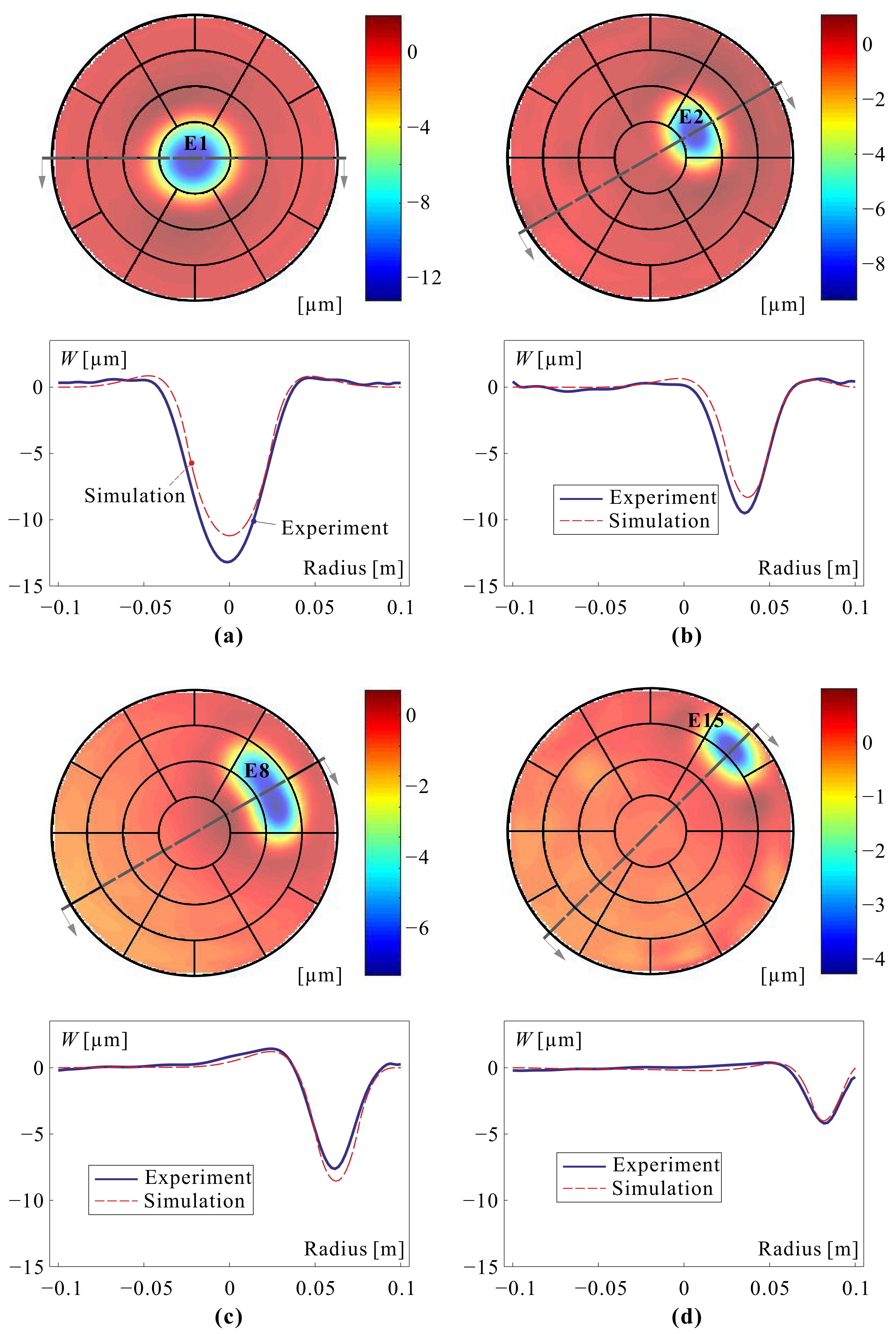
In absence of a dedicated system for the metrology of a spherical mirror of D = 200 mm, the influence functions were determined from dynamic measurements using a laser vibrometer Polytec PSV-400. The methodology and the experimental set-up are explained in detail in Reference [10]. The principle consists of covering the reflector surface with a scattering powder (Ardrox developer spray) and exciting it harmonically in the quasi-static range with the segmented electrodes. The amplitude of the harmonic response will follow closely the static shape of the deformation for the selected electrode. The frequency of 15 Hz was selected, well below the first resonance at f 1 = 85 Hz. The harmonic amplitude is 50 V with a bias of 65 V; the shape reconstruction involves 1921 scanned nodes.
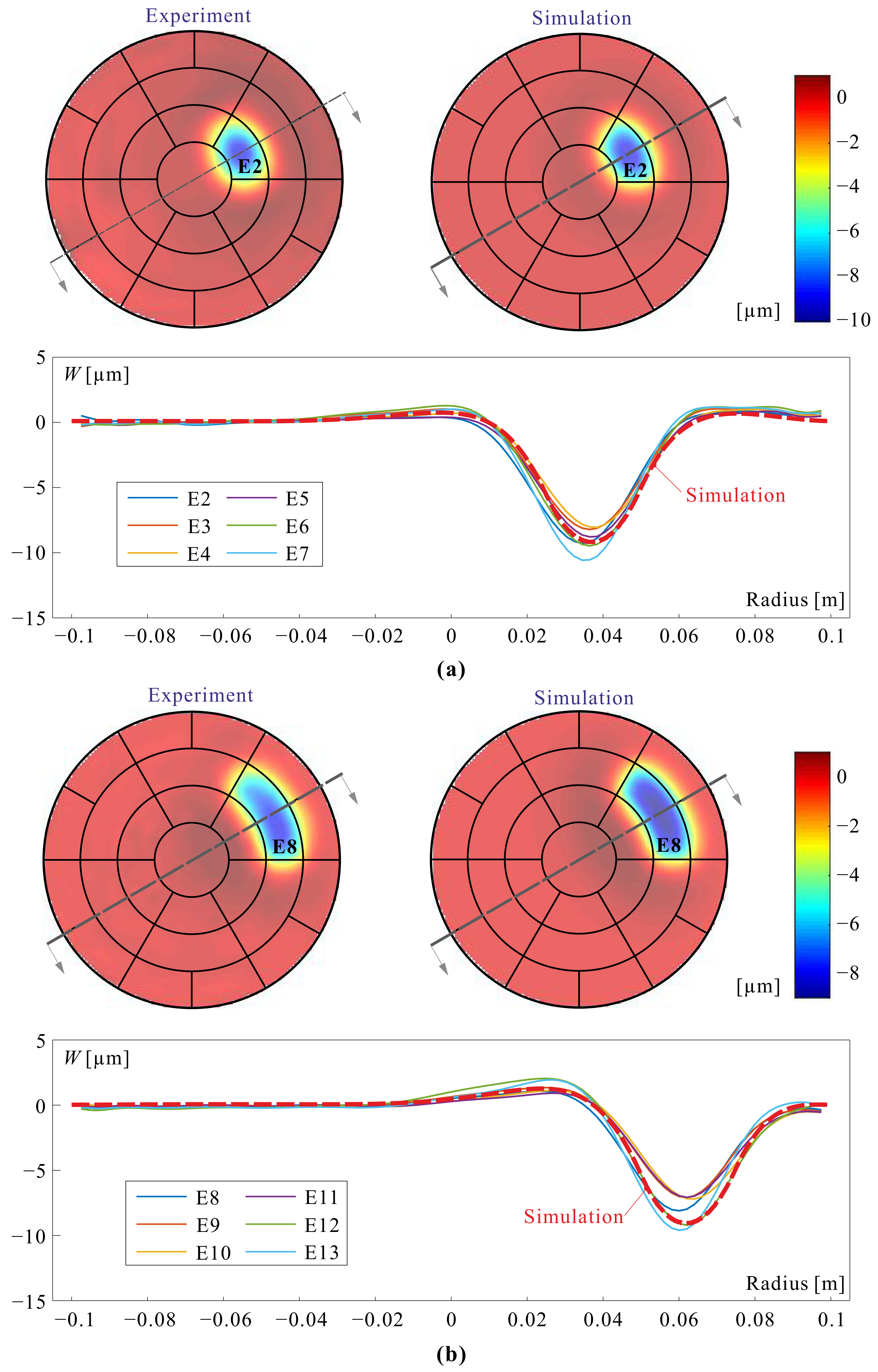
Figure 5 shows the influence functions of one electrode of each row (E 1 , E 2 , E 8 and E 15 ) for a voltage normalized to 100 V. The figure shows also cross-sections at 45° of the reflector shape. Figure 6 compares the cross sections of the influence functions of the 6 electrodes of the same row (successively rotated by 60°, together with a numerical simulation using a piezoelectric d 31 = 10 pC/N; this value gives the best fit between the experiments and the simulations (comparing with the values of Table 1 obtained on small samples suggests that the annealing of the demonstrator may be imperfect).
We now examine how the influence functions can be used to construct the optical (Zernike) modes within a given pupil.

4.2. Optical Modes

Let ϕ i be the influence function of electrode i, that is the vector of the surface displacements at n points within the pupil, for a unit voltage applied to electrode i. An optical mode z can be reconstructed within the pupil by solving the equation
z = i = 1 25 x i ϕ i
or
z = J x ,
where z is the vector containing the amplitudes of the optical mode at the n points in the pupil and J is the Jacobian, a rectangular matrix of order ( n , 25 ) in this case (the columns of J are the influence functions ϕ i ). x is the vector containing the voltages of the 25 controlled electrodes. The solution minimizing the fitting error is given by the Moore-Penrose pseudo inverse:
x = ( J T J ) 1 J T z .
However, the Jacobian tends to be ill-conditioned, leading to unnecessary voltages for some electrodes located outside the pupil. To alleviate this, we perform a Tikhonov regularization, also called Damped Least Squares (DLS) [17]. The pseudo inverse becomes
x = ( J T J + α 2 I ) 1 J T z .
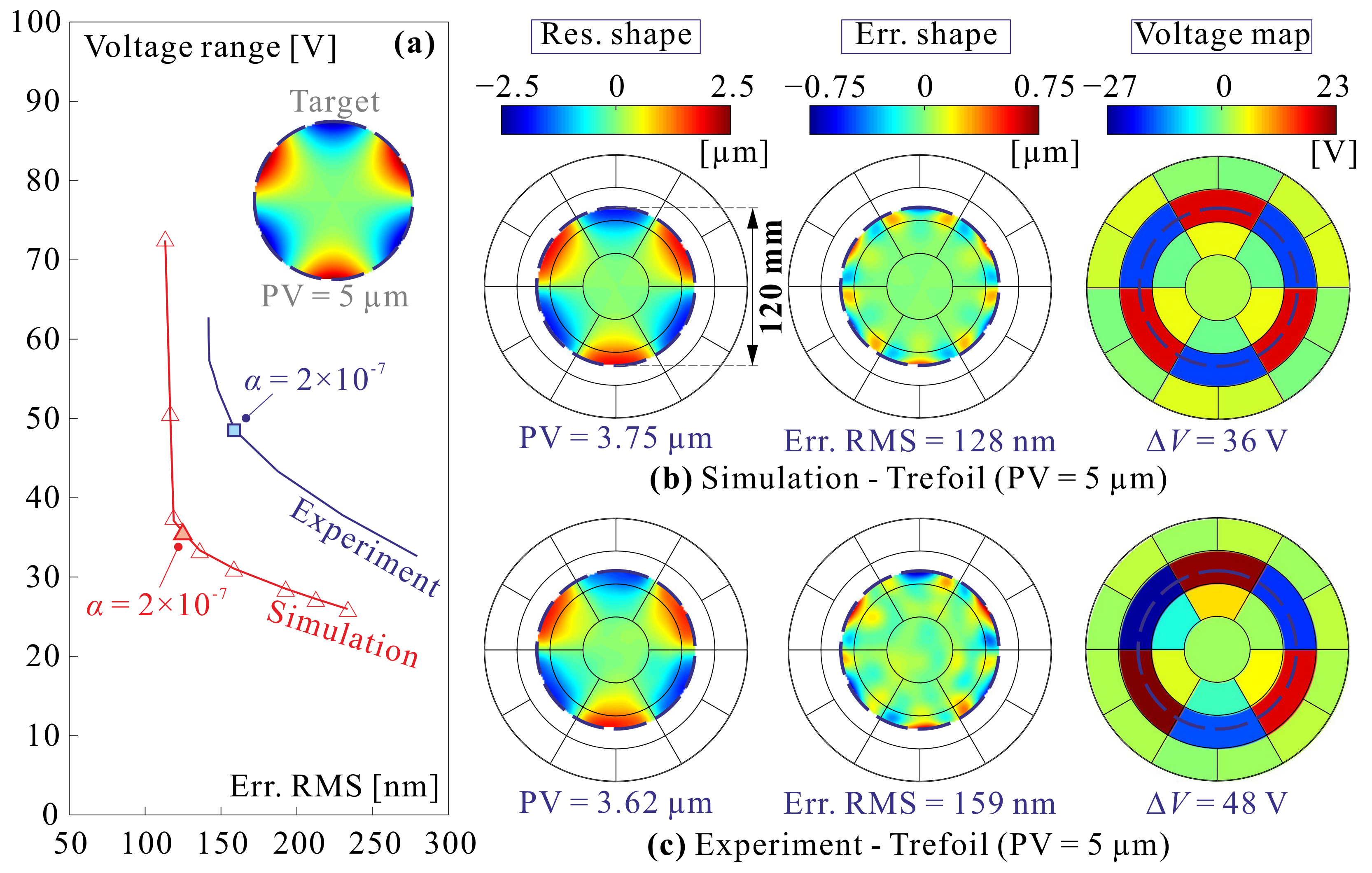
The damping factor α 2 handles the conflicting requirements of minimizing the fitting error and limiting the control actuator budget, that is the voltage range Δ V . The procedure is illustrated for the Trefoil mode in a pupil of 120 mm in Figure 7a. The L-curves express the trade-off between the voltage range and the RMS fitting error. For small values of α 2 , the voltage range decreases significantly without affecting significantly the fitting error. Figure 7b,c show the result based respectively on numerical and experimental influence functions, for α = 2 × 10 7 .
Figure 8 compares the mirror shape obtained with the experimental influence functions with the target for six optical modes: defocus (10 μ m), astigmatism, trefoil, and coma (5 μ m).

5. Conclusions

This paper discusses the design and manufacturing of a thin polymer spherical adaptive reflector of diameter D = 200 mm, controlled by a set of 25 independent electrodes arranged in a keystone configuration actuating a thin film of PVDF-TrFE in d 31 -mode. The electrostrictive material is spray coated. The results of the present study confirm that the active material can be modelled by a unidirectional quadratic model. The material has excellent properties if properly annealed; however, the dielectric constant ε r and the piezoelectric constant d 31 of the material obtained by spray coating appear to be slightly lower than those obtained earlier by spin coating. The experimental influence functions of the control electrodes are in good agreement with the numerical simulations and their better circular symmetry indicates a clear improvement in the manufacturing process, as compared to a previous study (comparing to Figure 15 of Reference [10]). Thanks to a special procedure to alleviate the ill-conditioning of the Jacobian, the reconstructed optical modes are achieved with reasonable voltages ( Δ V < 100 V, compliant with the ESA specifications).
Overall, the performances of the demonstrator are well in line with the expectations and compliant with the requirements of the ESA-MATS project, showing that the technology is a good candidate for controlling the surface figure of large lightweight reflectors.

Author Contributions

Conceptualization, K.W., T.G., D.R. and A.P.; software, K.W.; validation, K.W., T.G., D.R. and A.P.; writing–original draft preparation, A.P.; writing–review and editing, K.W. and A.P.; supervision, A.P. All authors have read and agreed to the published version of the manuscript.

Funding

This research has been supported by ESA-ESTEC in the framework of the GSTP program, project Multilayer Adaptive Thin Shell Reflectors for Future Space Telescopes (MATS). RFQ 3-14210/14/PA/NL.

Institutional Review Board Statement

Not applicable.

Informed Consent Statement

Not applicable.

Data Availability Statement

Data is contained within the article.

Acknowledgments

The authors wish to thank the Technical Officer, Gonçalo Rodrigues for his continuous support, and David Alaluf and Matthieu Michiels for their contribution in the early stage of this project.

Conflicts of Interest

The authors declare no conflict of interest.

Abbreviations

The following abbreviations are used in this manuscript:
ESAEuropean Space Agency
DLSDamped Least Squares
GSTPGeneral Support Technology Programme
MATSMultilayer Adaptive Thin Shell Reflectors for Future Space Telescopes
MEKMethyl ethyl ketone
MIBKMethyl isobutyl ketone
PDCMSPulse DC Magnetron Sputtering
PETPolyethylene terephthalate
PVPeak to Valley
PVDF-TrFEPoly(vinylidene fluoride-co-trifluoroethylene)
PZTLead Zirconate Titanate
RMSRoot mean square
ULBUniversité Libre de Bruxelles

References

  1. Hedgepeth, J.M. Accuracy potentials for large space antenna reflectors with passive structure. J. Spacecr. Rocket. 1982, 19, 211–217. [Google Scholar] [CrossRef]
  2. Bekey, I. Advanced Space System Concepts and Technologies: 2010–2030+; American Institute of Aeronautics and Astronautics: Reston, VA, USA, 2003. [Google Scholar]
  3. Jenkins, C.H. Gossamer Spacecraft: Membrane and Inflatable Structures Technology for Space Applications; American Institute of Aeronautics and Astronautics: Reston, VA, USA, 2001. [Google Scholar]
  4. Marker, D.K.; Jenkins, C.H. Surface precision of optical membranes with curvature. Opt. Express 1997, 1, 324–331. [Google Scholar] [CrossRef] [PubMed]
  5. Flint, E.; Lindler, J.; Hall, J.; Rankine, C.; Regelbrugge, M. Overview of form stiffened thin film shell characteristic behavior. In Proceedings of the 47th AIAA/ASME/ASCE/AHS/ASC Structures, Structural Dynamics, and Materials Conference, Newport, RI, USA, 1–4 May 2006; p. 1900. [Google Scholar]
  6. Flint, E.; Bales, G.; Glaese, R.; Bradford, R. Experimentally characterizing the dynamics of 0.5 m diameter doubly curved shells made from thin films. In Proceedings of the 44th AIAA/ASME/ASCE/AHS/ASC Structures, Structural Dynamics, and Materials Conference, Norfolk, VA, USA, 7–10 April 2003; p. 1831. [Google Scholar]
  7. Chodimella, S.; Moore, J.; Otto, J.; Fang, H. Design evaluation of a large aperture deployable antenna. In Proceedings of the 47th AIAA/ASME/ASCE/AHS/ASC Structures, Structural Dynamics, and Materials Conference, Newport, RI, USA, 1–4 May 2006; p. 1603. [Google Scholar]
  8. Haftka, R.T.; Adelman, H.M. An analytical investigation of shape control of large space structures by applied temperatures. AIAA J. 1985, 1, 450–457. [Google Scholar] [CrossRef]
  9. Fang, H.; Quijano, U.; Bach, V.; Hill, J.; Wang, K.W. Experimental study of a membrane antenna surface adaptive control system. In Proceedings of the 52nd AIAA/ASME/ASCE/AHS/ASC Structures, Structural Dynamics and Materials Conference, Denver, CO, USA, 4–7 April 2011; p. 1828. [Google Scholar]
  10. Wang, K.; Godfroid, T.; Robert, D.; Preumont, A. Electrostrictive PVDF-TrFE thin film actuators for the control of adaptive thin shell reflectors. Actuators 2020, 9, 53. [Google Scholar] [CrossRef]
  11. Wang, K.; Alaluf, D.; Preumont, A. Thermal balance and active damping of a piezoelectric deformable mirror for adaptive optics. Actuators 2019, 8, 75. [Google Scholar] [CrossRef] [Green Version]
  12. Preumont, A.; Alaluf, D.; Wang, K.; Rodrigues, G. Adaptive thin shell reflectors for future space telescopes. In Proceedings of the 14th European Conference on Spacecraft Structures, Materials and Environmental Testing (ECSSMET), Toulouse, France, 27–30 September 2016. [Google Scholar]
  13. Wang, K. Piezoelectric Adaptive Mirrors for Ground-Based and Space Telescopes. Ph.D. Thesis, Active Structures Laboratory, Université Libre de Bruxelles, Brussels, Belgium, 2019. [Google Scholar]
  14. Preumont, A. Vibration Control of Active Structures, an Introduction, 4th ed.; Springer International Publishing: Cham, Switzerland, 2018. [Google Scholar]
  15. Wang, K.; Alaluf, D.; Rodrigues, G.; Preumont, A. Precision shape control of ultra thin shells with strain actuators. J. Appl. Comput. Mech. 2020, in press. [Google Scholar]
  16. Li, F.; Jin, L.; Xu, Z.; Zhang, S. Electrostrictive effect in ferroelectrics: An alternative approach to improve piezoelectricity. Appl. Phys. Rev. 2014, 1, 011103. [Google Scholar] [CrossRef] [Green Version]
  17. Buss, S.R. Introduction to inverse kinematics with jacobian transpose, pseudoinverse and damped least squares methods. IEEE Robot. Autom. 2004, 17, 16. [Google Scholar]
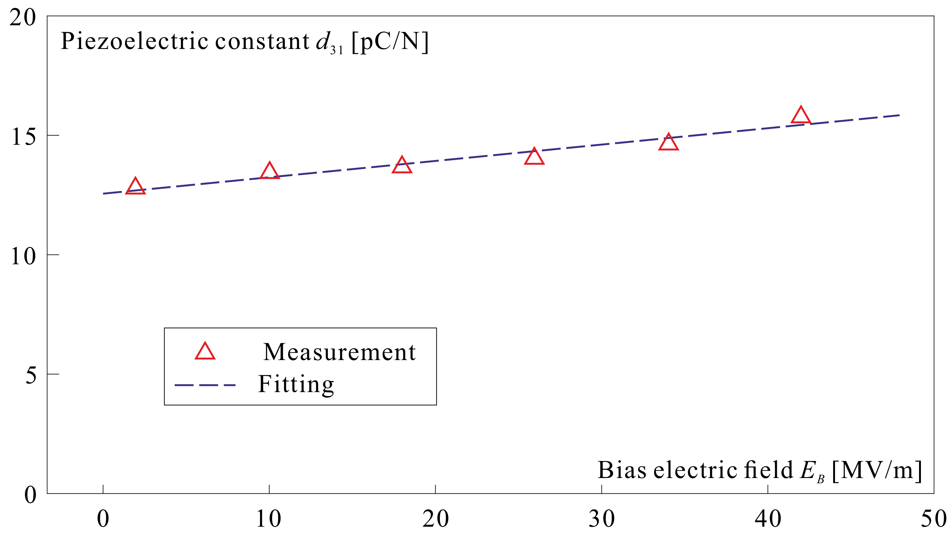
Figure 1. Piezoelectric coefficient d 31 as a function of the bias electric field E B . The electrostrictive constant Q 33 can be obtained from the slope according to Equation (6).
Actuators 10 00007 g001
Figure 2. Flow chart of the manufacturing sequence of the Multilayer Adaptive Thin Shell Reflectors for Future Space Telescopes (MATS) demonstrator.
Actuators 10 00007 g002
Figure 3. Keystone electrodes layout and electrical connections.
Actuators 10 00007 g003
Figure 4. Demonstrators developed in the MATS project, mounted in their support. (Left) Spin coated reflector discussed in Reference [10]. (Right) Spray coated reflector of the present study.
Actuators 10 00007 g004
Figure 5. Experimental influence functions of electrodes E 1 , E 2 , E 8 and E 15 for a voltage normalized to 100 V and cross section at 45° of the reflector shape.
Actuators 10 00007 g005
Figure 6. Comparison between experimental 45° cross sections of the influence functions of the six electrodes of the same row (order: 2 and 3) and a numerical simulation with d 31 = 10 pC/N.
Actuators 10 00007 g006
Figure 7. Trefoil mode with a Peak to Valley (PV) amplitude of 5 μ m in a pupil of 120 mm. (a) L-curves showing the trade-off between the voltage budget and the fitting error. (b) Reflector shape in the pupil, fitting error and voltage map using the numerical influence functions and α = 2 × 10 7 . (c) Same with the experimental influence functions.
Actuators 10 00007 g007
Figure 8. Six optical modes in a pupil of 120 mm. From top to bottom: Target, RMS fitting error, Reconstructed surface from the experimental influence functions.
Actuators 10 00007 g008
Table 1. Estimation on material parameters (PVDF-TrFE).
Deposition TechniqueSpin CoatingSpray Coating
Dielectric constant ϵ r [/]11.869.6
Piezoelectric constant d 31 [ pC / N ] ( E B = 0 )13.5412.54
Electrostrictive constant Q 33 [ m 4 / C 2 ] −12.65−13.81
Remnant polarization P s [ C / m 2 ] 0.01520.0157
0.01630.0144
Publisher’s Note: MDPI stays neutral with regard to jurisdictional claims in published maps and institutional affiliations.