
Motion Characteristics of a Clutch Actuator for Heavy-Duty Vehicles with Automated Mechanical Transmission


Abstract
:1. Introduction
2. Clutch Modeling and Analyzing
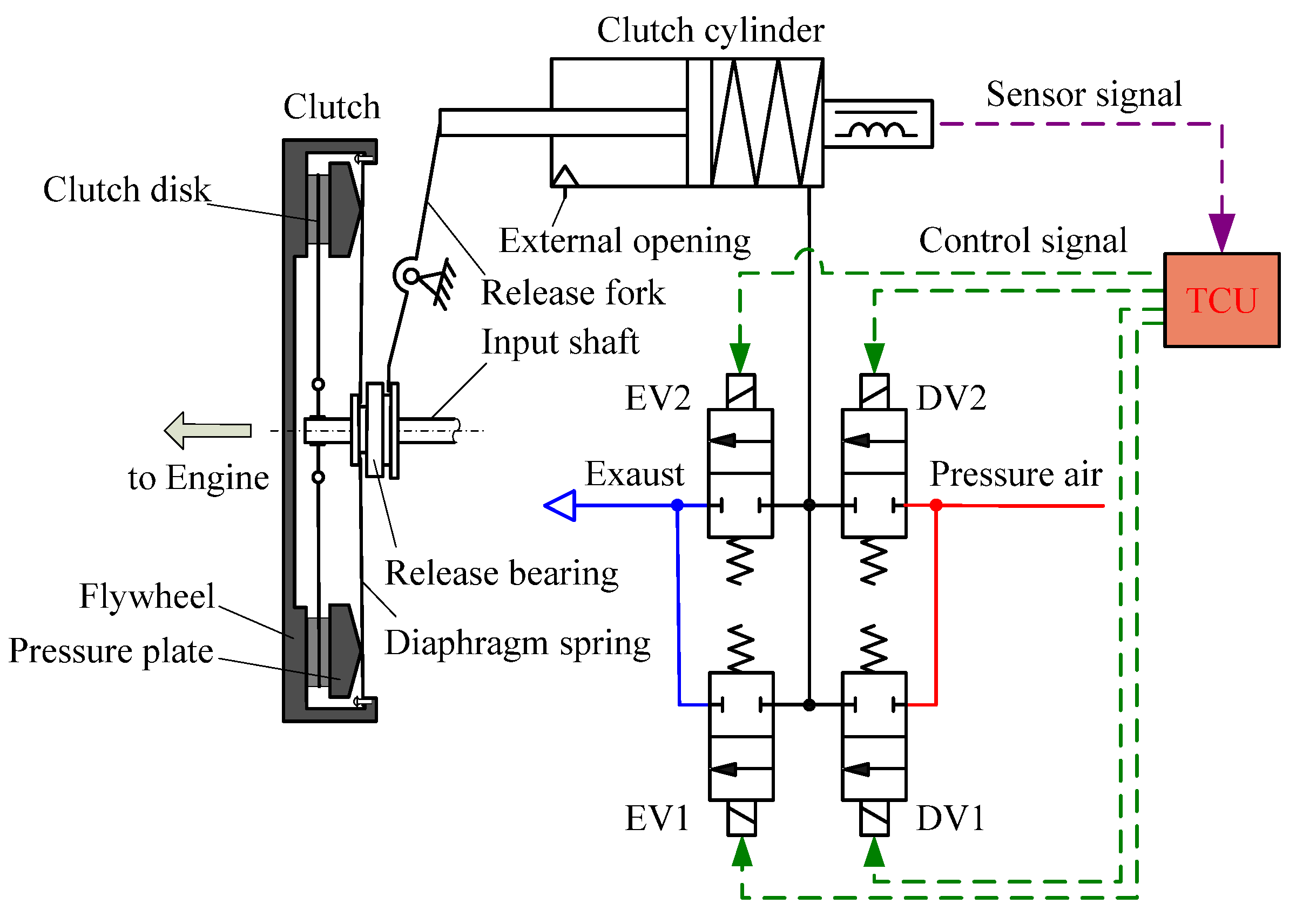
2.1. Automatic Clutch System
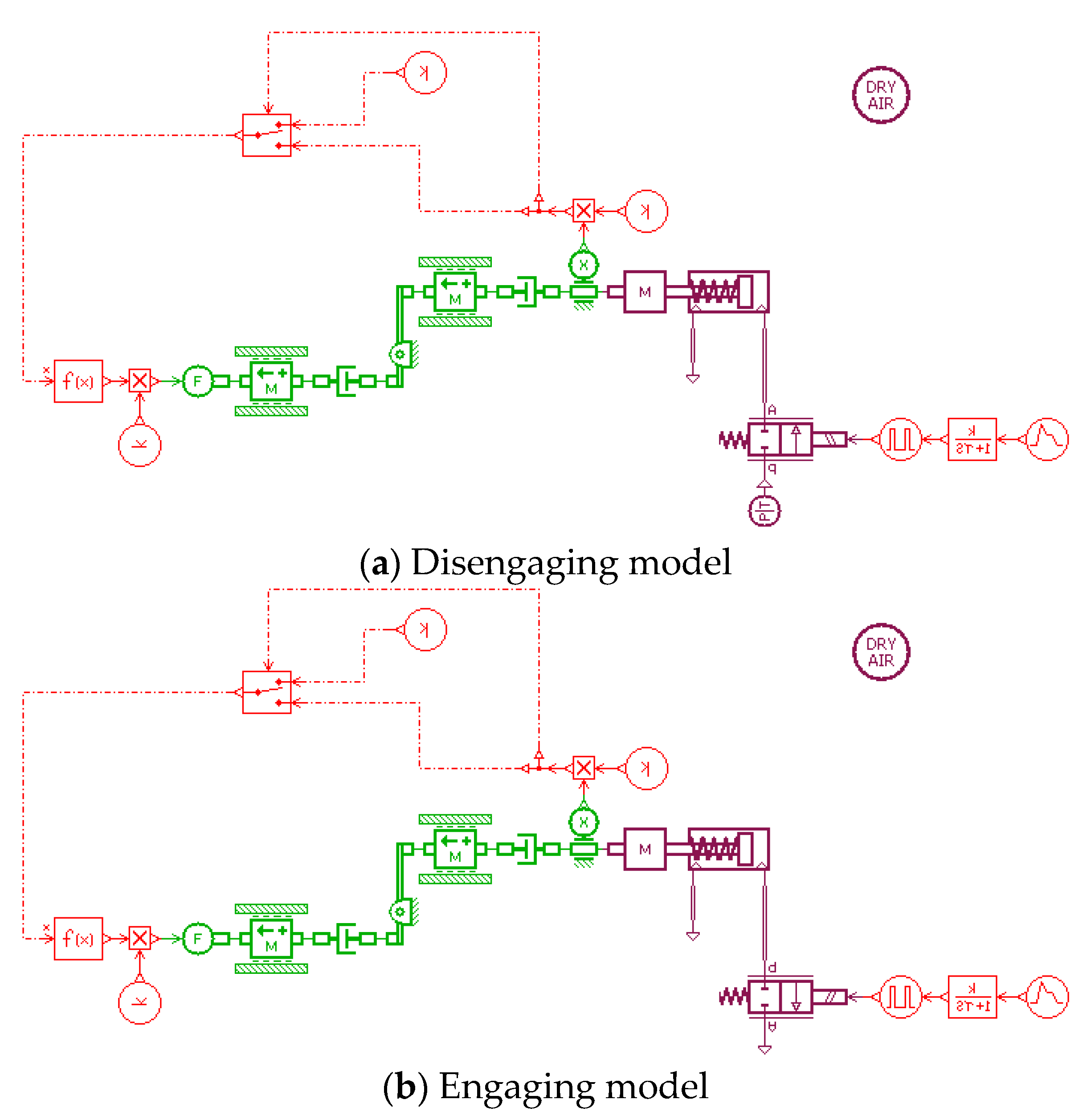
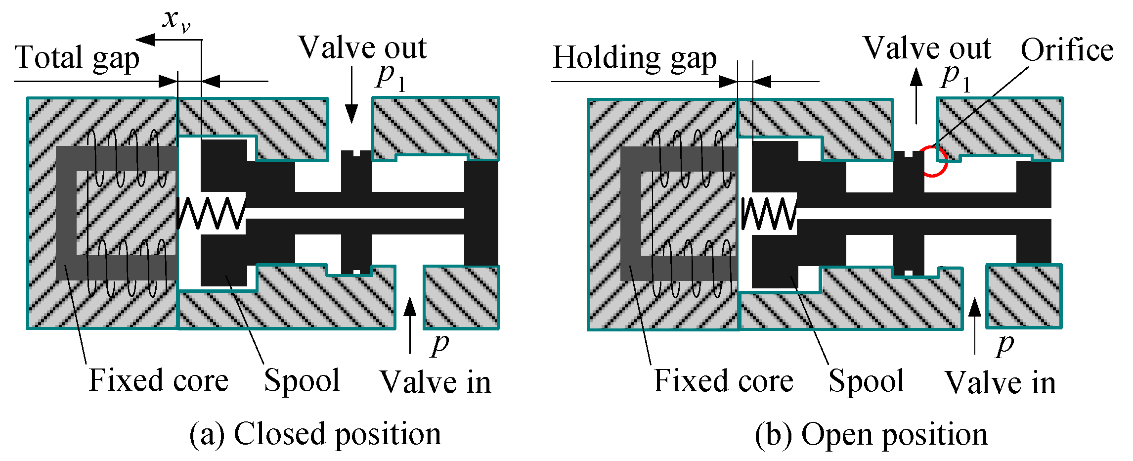
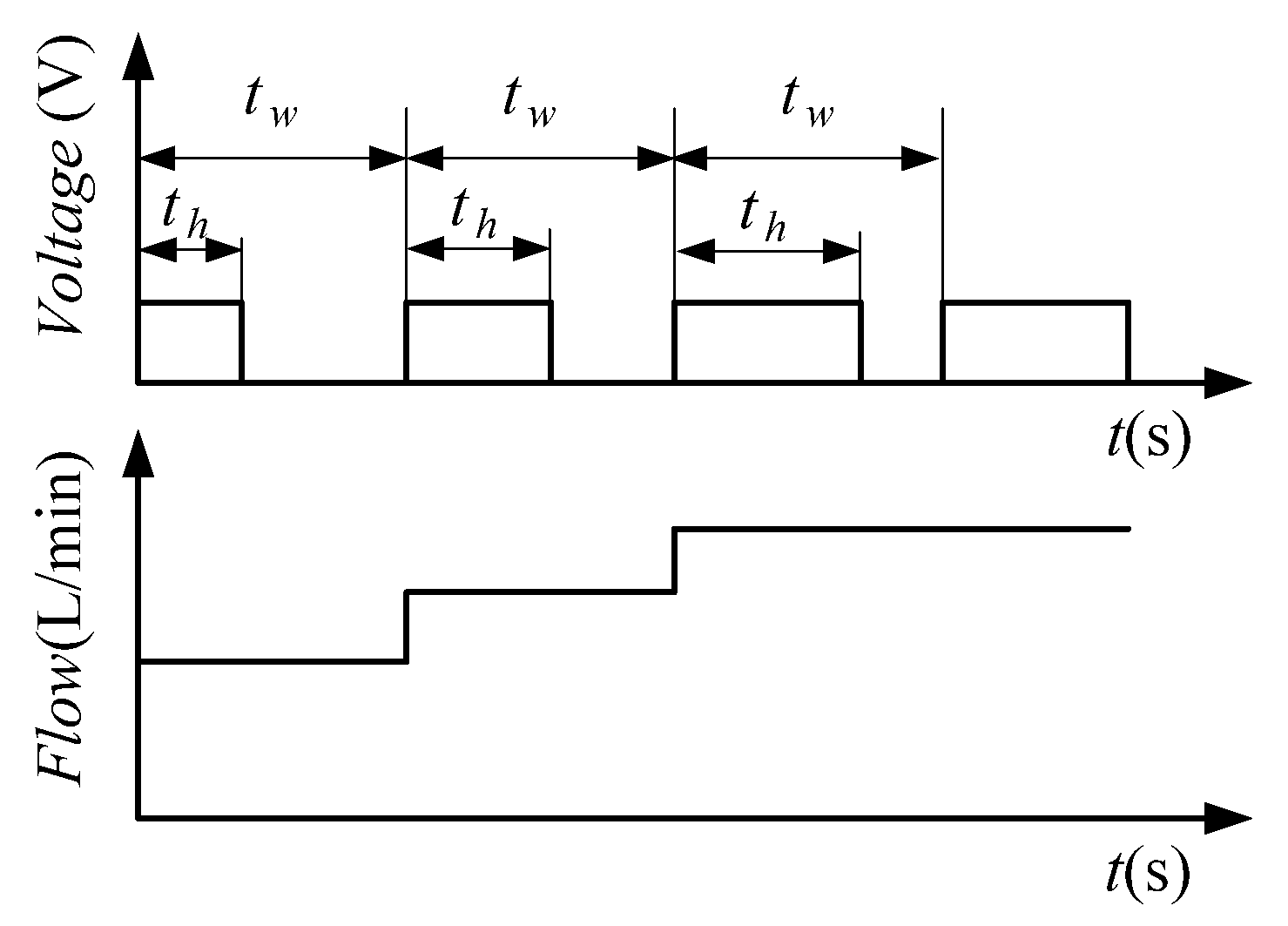
2.2. Solenoid Valve Modeling
2.3. Clutch Force and Transmitted Torque Analysis
2.3.1. Clutch Force Analysis
2.3.2. Clutch-Transmitted Torque Analysis
2.4. Clutch Cylinder Modeling
3. Main Evaluation Parameters of the Motion Characteristics
4. Simulation Analysis
4.1. Numerical Simulatin of the Diaphragm Force and the Release Bearing Force
4.2. Simulation Analysis of the Clutch Actuator
5. Test
5.1. Motion Characteristics during the Engaging Process
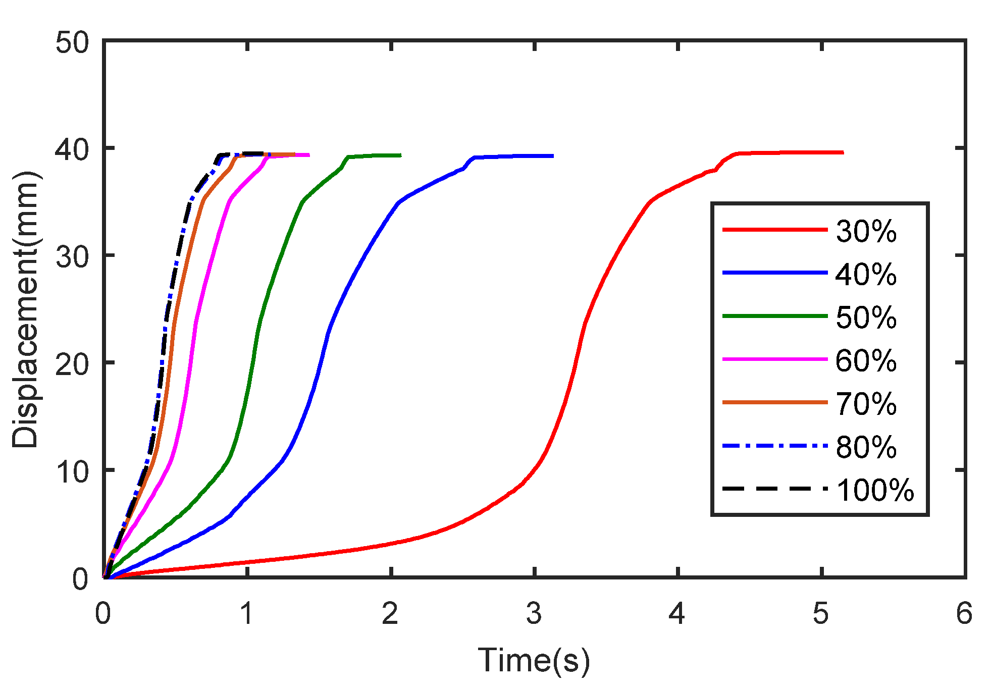
5.1.1. Motion Characteristics Using the QESV
5.1.2. Motion Characteristics Using the SESV
5.1.3. Motion Characteristics Using a Combination of the QESV and the SESV
5.2. Motion Characteristics during the Disengaging Process
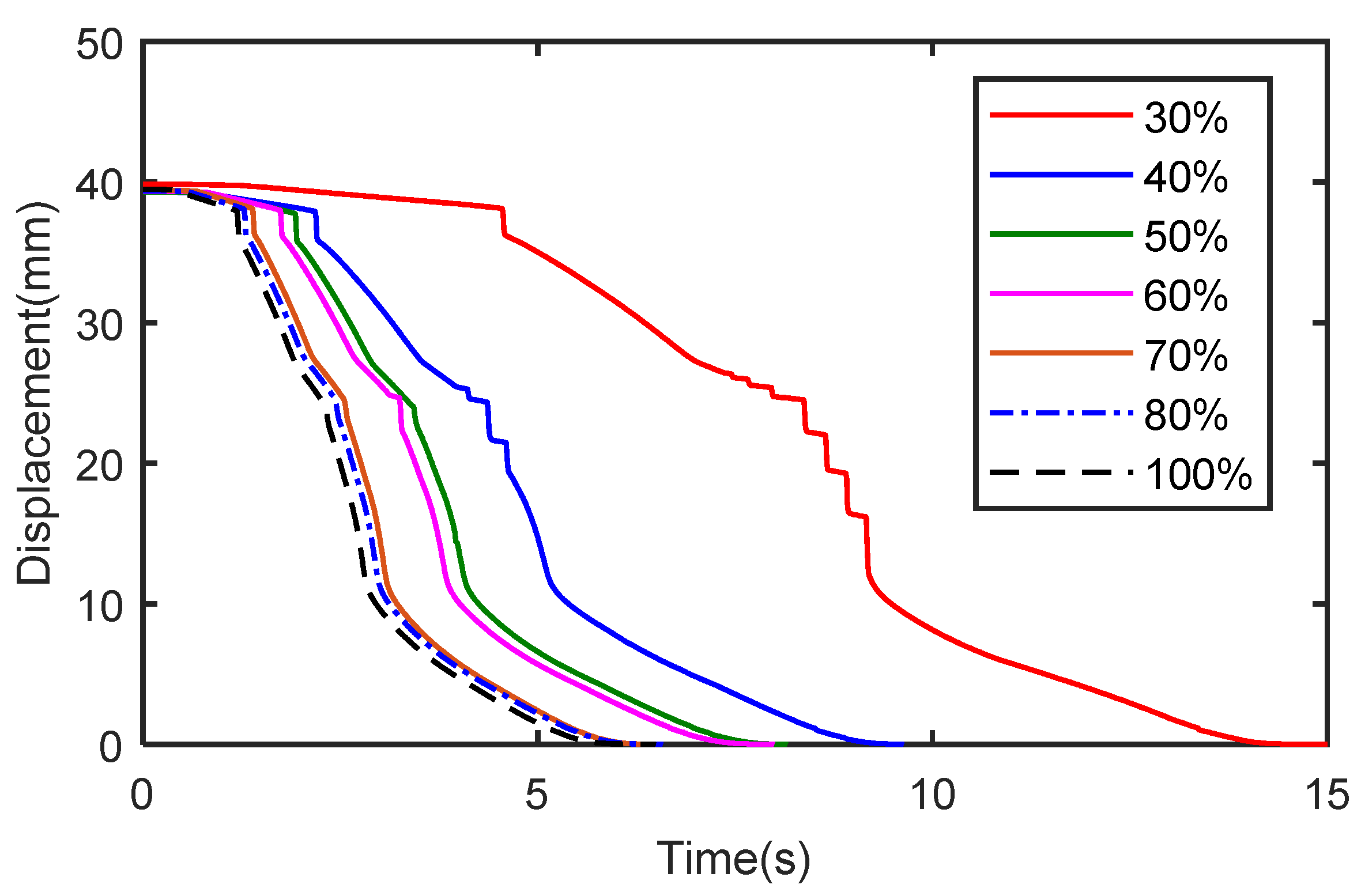
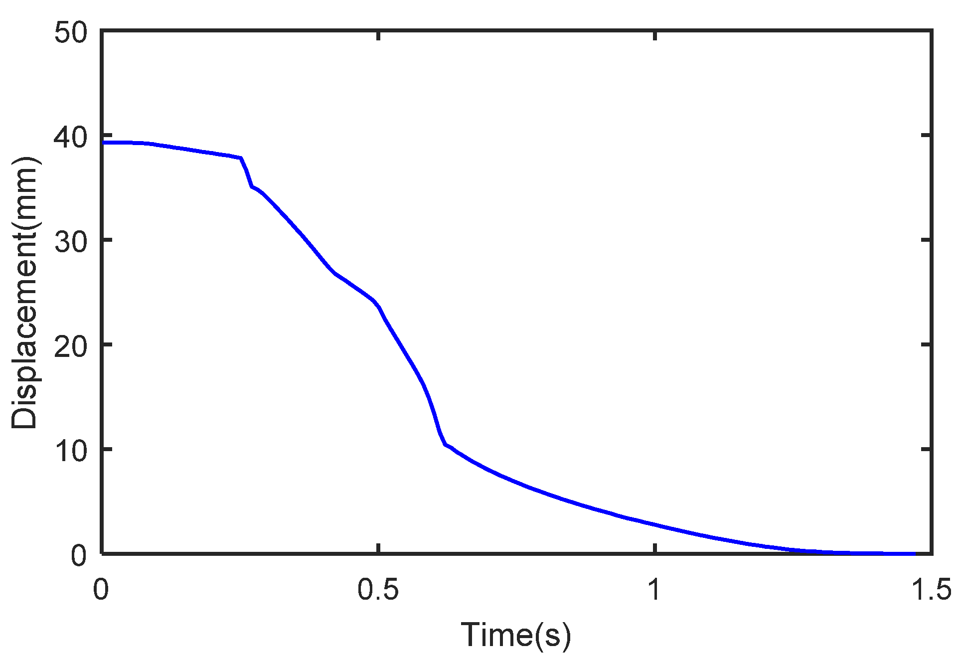
5.2.1. Motion Characteristics Using the QDSV
5.2.2. Motion Characteristics Using the SDSV
5.2.3. Motion Characteristics Using a Combination of the QDSV and the SDSV
6. Brief Descriptions of Actuator Motion Characteristics
7. Conclusions
Author Contributions
Funding
Institutional Review Board Statement
Informed Consent Statement
Data Availability Statement
Conflicts of Interest
References
- Gao, B.; Chen, H.; Ma, Y.; Sanada, K. Design of nonlinear shaft torque observer for trucks with Automated Manual Transmission. Mechatronics 2011, 21, 1034–1042. [Google Scholar] [CrossRef]
- Gao, B.-Z.; Chen, H.; Lu, X.-H.; Sanada, K. Improved optimal controller for start-up of amt trucks in consideration of driver’s intention. Int. J. Automot. Technol. 2013, 14, 213–220. [Google Scholar] [CrossRef]
- Li, Y.; Li, L. Parameter Estimation of a Countershaft Brake for Heavy-Duty Vehicles with Automated Mechanical Transmission. Processes 2021, 9, 1036. [Google Scholar] [CrossRef]
- Hofman, T.; Ebbesen, S.; Guzzella, L. Topology Optimization for Hybrid Electric Vehicles with Automated Transmissions. IEEE Trans. Veh. Technol. 2012, 61, 2442–2451. [Google Scholar] [CrossRef] [Green Version]
- Gao, B.; Chen, H.; Liu, Q.; Chu, H. Position Control of Electric Clutch Actuator Using a Triple-Step Nonlinear Method. IEEE Trans. Ind. Electron. 2014, 61, 6995–7003. [Google Scholar] [CrossRef]
- Vacca, F.; De Pinto, S.; Hartavi Karci, A.E.; Gruber, P.; Viotto, F.; Cavallino, C.; Rossi, J.; Sorniotti, A. On the Energy Efficiency of Dual Clutch Transmissions and Automated Manual Trans-missions. Energies 2017, 10, 1562. [Google Scholar] [CrossRef]
- Liu, Y.F.; Dong, P.; Liu, Y.; Xu, X.Y. Design and application of electric oil pump in automatic transmission for efficiency improvement and start-stop function. J. Cent. South Univ. 2016, 23, 570–580. [Google Scholar] [CrossRef]
- Nakazawa, T.; Hattori, H.; Tarutani, I.; Yasuhara, S.; Inoue, T. Influence of pin profile curve on continuously variable transmission (CVT) chain noise and vibration. Mech. Mach. Theory 2020, 154, 104027. [Google Scholar] [CrossRef]
- Onumata, Y.; Zhao, H.; Wang, C.; Morina, A.; Neville, A. Interactive Effect between Organic Friction Modifiers and Additives on Friction at Metal Pushing V-Belt CVT Components. Tribol. Trans. 2017, 61, 474–481. [Google Scholar] [CrossRef]
- Meng, F.; Zhang, H.; Cao, D.; Chen, H. System Modeling and Pressure Control of a Clutch Actuator for Heavy-Duty Automatic Transmission Systems. IEEE Trans. Veh. Technol. 2015, 65, 4865–4874. [Google Scholar] [CrossRef]
- Schoeftner, J.; Ebner, W. Simulation model of an electrohydraulic-actuated double-clutch transmission vehicle: Modelling and system design. Veh. Syst. Dyn. 2017, 55, 1865–1883. [Google Scholar] [CrossRef]
- Wang, H.; Wang, B.; Pi, D.; Wang, E.; Wang, X. Two-Layer Structure Control of an Automatic Mechanical Transmission Clutch During Hill Start for Heavy-Duty Vehicles. IEEE Access 2020, 8, 49617–49628. [Google Scholar] [CrossRef]
- Marcos, L.B.; Terra, M.H. Markovian filtering for driveshaft torsion estimation in heavy vehicles. Control Eng. Pract. 2020, 102, 104552. [Google Scholar] [CrossRef]
- Szimandl, B.; Németh, H. Dynamic hybrid model of an electro-pneumatic clutch system. Mechatronics 2013, 23, 21–36. [Google Scholar] [CrossRef]
- Song, M.; Wang, H.; Liu, H.; Peng, P.; Wang, X.; Pi, D.; Yang, C.; He, G. Double-layer Control of an Automatic Mechanical Transmission Clutch during Commercial Vehicle Start-up. Stroj. Vestn. J. Mech. Eng. 2019, 65, 515–524. [Google Scholar] [CrossRef]
- Pisaturo, M.; Senatore, A. Thermal Compensation Control Strategy in Automated Dry Clutch Engagement Dynamics and Launch Manoeuvre. Int. J. Automot. Technol. 2019, 20, 1089–1101. [Google Scholar] [CrossRef]
- Gao, B.; Li, X.; Zeng, X.; Chen, H. Nonlinear control of direct-drive pump-controlled clutch actuator in consideration of pump efficiency map. Control Eng. Pract. 2019, 91, 104110. [Google Scholar] [CrossRef]
- Gao, Q.; Zhu, Y.; Luo, Z.; Bruno, N. Investigation on adaptive pulse width modulation control for high speed on/off valve. J. Mech. Sci. Technol. 2020, 34, 1711–1722. [Google Scholar] [CrossRef]
- Wu, S.; Zhao, X.; Li, C.; Jiao, Z.; Qu, F. Multiobjective Optimization of a Hollow Plunger Type Solenoid for High Speed On/Off Valve. IEEE Trans. Ind. Electron. 2017, 65, 3115–3124. [Google Scholar] [CrossRef]
- Zhong, Q.; Zhang, B.; Yang, H.-Y.; Ma, J.-E.; Fung, R.-F. Performance analysis of a high-speed on/off valve based on an intelligent pulse-width modulation control. Adv. Mech. Eng. 2017, 9, 1687814017733247. [Google Scholar] [CrossRef]
- Wang, Q.; Yang, F.; Yang, Q.; Chen, J.; Guan, H. Experimental analysis of new high-speed powerful digital solenoid valves. Energy Convers. Manag. 2011, 52, 2309–2313. [Google Scholar] [CrossRef]
- Zhao, J.; Yue, P.; Wei, K. Eddy current effects on the dynamic response of high-speed solenoid valve for common rail injector. Int. J. Appl. Electromagn. Mech. 2020, 62, 607–618. [Google Scholar] [CrossRef]
- Zhao, J.; Wang, M.; Wang, Z.; Grekhov, L.; Qiu, T.; Ma, X. Different boost voltage effects on the dynamic response and energy losses of high-speed solenoid valves. Appl. Therm. Eng. 2017, 123, 1494–1503. [Google Scholar] [CrossRef]
- Taghizadeh, M.; Ghaffari, A.; Najafi, F. Modeling and identification of a solenoid valve for PWM control applications. Comptes Rendus Mec. 2009, 337, 131–140. [Google Scholar] [CrossRef]
- Lin, Z.; Wei, Q.; Ji, R.; Huang, X.; Yuan, Y.; Zhao, Z. An Electro-Pneumatic Force Tracking System using Fuzzy Logic Based Volume Flow Control. Energies 2019, 12, 4011. [Google Scholar] [CrossRef] [Green Version]
- Pawananont, K.; Leephakpreeda, T. Sequential Control of Multichannel On–Off Valves for Linear Flow Characteristics Via Averaging Pulse Width Modulation Without Flow Meter: An Application for Pneumatic Valves. J. Dyn. Syst. Meas. Control 2018, 141. [Google Scholar] [CrossRef]
- Pipan, M.; Herakovič, N. Volume Flow Characterization of PWM-Controlled Fast-Switching Pneumatic Valves. Stroj. Vestn. J. Mech. Eng. 2016, 62, 543–550. [Google Scholar] [CrossRef]
- Pipan, M.; Herakovic, N. Closed-loop volume flow control algorithm for fast switching pneumatic valves with PWM signal. Control Eng. Pract. 2018, 70, 114–120. [Google Scholar] [CrossRef]
- Dong, J.; Shi, J.; Liu, C.; Yu, T. Research of Pneumatic Polishing Force Control System Based on High Speed On/off with PWM Con-trolling. Robot. Comput. Integr. Manuf. 2021, 70, 102133. [Google Scholar] [CrossRef]
- Yan, Z.; Yan, F.; Liang, J.; Duan, Y. Detailed Modeling and Experimental Assessments of Automotive Dry Clutch Engagement. IEEE Access 2019, 7, 59100–59113. [Google Scholar] [CrossRef]
- Li, L.; Wang, X.; Qi, X.; Li, X.; Cao, D.; Zhu, Z. Automatic Clutch Control Based on Estimation of Resistance Torque for AMT. IEEE/ASME Trans. Mechatron. 2016, 21, 2682–2693. [Google Scholar] [CrossRef]
- Park, J.; Choi, S.; Oh, J.; Eo, J. Adaptive torque tracking control during slip engagement of a dry clutch in vehicle powertrain. Mech. Mach. Theory 2019, 134, 249–266. [Google Scholar] [CrossRef]
- Kim, S.; Oh, J.J.; Choi, S.B. Driveline Torque Estimations for a Ground Vehicle with Dual-Clutch Transmission. IEEE Trans. Veh. Technol. 2017, 67, 1977–1989. [Google Scholar] [CrossRef]
- Myklebust, A.; Eriksson, L. Modeling, Observability, and Estimation of Thermal Effects and Aging on Transmitted Torque in a Heavy Duty Truck With a Dry Clutch. IEEE/ASME Trans. Mechatron. 2014, 20, 61–72. [Google Scholar] [CrossRef]
- Zhao, Z.; Li, X.; He, L.; Wu, C.; Hedrick, J.K. Estimation of Torques Transmitted by Twin-Clutch of Dry Dual-Clutch Transmission During Vehicle’s Launching Process. IEEE Trans. Veh. Technol. 2016, 66, 4727–4741. [Google Scholar] [CrossRef]
- Park, J.; Choi, S. Optimization Method of Reference Slip Speed in Clutch Slip Engagement in Vehicle Powertrain. Int. J. Automot. Technol. 2021, 22, 55–67. [Google Scholar] [CrossRef]
- Temporelli, R.; Boisvert, M.; Micheau, P. Accurate Clutch Slip Controllers During Vehicle Steady and Acceleration States. IEEE/ASME Trans. Mechatron. 2018, 23, 2078–2089. [Google Scholar] [CrossRef]
- Skugor, B.; Deur, J.; Ivanovic, V. E-Clutch Torque Control Including Compensation of Thermal Expansion Effects. IEEE Trans. Veh. Technol. 2019, 69, 246–257. [Google Scholar] [CrossRef]
- Della Gatta, A.; Iannelli, L.; Pisaturo, M.; Senatore, A.; Vasca, F. A survey on modeling and engagement control for automotive dry clutch. Mechatronics 2018, 55, 63–75. [Google Scholar] [CrossRef]


| Duty (%) | Displacement (mm) | Time (s) | Average Velocity (mm/s) | Normalized Velocity (%) |
|---|---|---|---|---|
| 30 | 39.50 | 14.33 | 2.76 | 13.28 |
| 40 | 39.50 | 6.11 | 6.46 | 31.07 |
| 50 | 39.50 | 4.34 | 9.10 | 43.77 |
| 60 | 39.50 | 2.91 | 13.57 | 65.27 |
| 70 | 39.50 | 2.41 | 16.39 | 78.84 |
| 80 | 39.50 | 2.27 | 17.40 | 83.69 |
| 100 | 39.50 | 1.90 | 20.79 | 100 |
| Duty (%) | Displacement (mm) | Time (s) | Average Velocity (mm/s) | Normalized Velocity (%) |
|---|---|---|---|---|
| 30 | 39.50 | 15.11 | 2.61 | 42.86 |
| 40 | 39.50 | 9.63 | 4.10 | 72.41 |
| 50 | 39.50 | 8.17 | 4.83 | 79.31 |
| 60 | 39.50 | 7.99 | 4.94 | 81.12 |
| 70 | 39.50 | 6.58 | 6.00 | 98.52 |
| 80 | 39.50 | 6.50 | 6.08 | 99.84 |
| 100 | 39.50 | 6.49 | 6.09 | 100 |
| Valve | Duty (%) | Average Velocity (mm/s) | Velocity Modulation Percentage (%) |
|---|---|---|---|
| QESV | 30 | 2.76 | 10.27 |
| 40 | 6.46 | 24.04 | |
| 50 | 9.10 | 33.87 | |
| 60 | 13.57 | 50.50 | |
| 70 | 16.39 | 61.00 | |
| 80 | 17.40 | 64.76 | |
| 100 | 20.79 | 77.37 | |
| SESV | 30 | 2.61 | 9.71 |
| 40 | 4.10 | 15.26 | |
| 50 | 4.83 | 17.98 | |
| 60 | 4.94 | 18.38 | |
| 70 | 6.00 | 22.33 | |
| 80 | 6.08 | 22.63 | |
| 100 | 6.09 | 22.66 | |
| QESV and SESV | 100 | 26.87 | 100 |
| Duty (%) | Displacement (mm) | Time (s) | Average Velocity (mm/s) | Normalized Velocity (%) |
|---|---|---|---|---|
| 30 | 39.50 | 5.15 | 7.67 | 22.53 |
| 40 | 39.50 | 3.13 | 12.62 | 37.06 |
| 50 | 39.50 | 2.07 | 19.08 | 56.04 |
| 60 | 39.50 | 1.43 | 27.62 | 81.12 |
| 70 | 39.50 | 1.33 | 29.70 | 87.22 |
| 80 | 39.50 | 1.18 | 33.47 | 98.30 |
| 100 | 39.50 | 1.16 | 34.05 | 100 |
| Duty (%) | Displacement (mm) | Time (s) | Average Velocity (mm/s) | Normalized Velocity (%) |
|---|---|---|---|---|
| 30 | 39.50 | 11.78 | 3.35 | 25.95 |
| 40 | 39.50 | 5.20 | 7.60 | 58.87 |
| 50 | 39.50 | 4.37 | 9.04 | 70.02 |
| 60 | 39.50 | 3.71 | 10.65 | 82.49 |
| 70 | 39.50 | 3.36 | 11.76 | 91.09 |
| 80 | 39.50 | 3.10 | 12.74 | 98.68 |
| 100 | 39.50 | 3.06 | 12.91 | 100 |
| Valve | Duty (%) | Average Velocity (mm/s) | Velocity Modulation Percentage (%) |
|---|---|---|---|
| QDSV | 30 | 7.67 | 18.06 |
| 40 | 12.62 | 29.71 | |
| 50 | 19.08 | 44.93 | |
| 60 | 27.62 | 65.03 | |
| 70 | 29.48 | 69.41 | |
| 80 | 33.47 | 78.81 | |
| 100 | 34.05 | 80.17 | |
| SDSV | 30 | 3.35 | 7.89 |
| 40 | 7.60 | 17.90 | |
| 50 | 9.04 | 21.29 | |
| 60 | 10.65 | 25.08 | |
| 70 | 11.76 | 27.69 | |
| 80 | 12.74 | 30.00 | |
| 100 | 12.91 | 30.40 | |
| QDSV and SDSV | 100 | 42.47 | 100 |
Publisher’s Note: MDPI stays neutral with regard to jurisdictional claims in published maps and institutional affiliations. |
© 2021 by the authors. Licensee MDPI, Basel, Switzerland. This article is an open access article distributed under the terms and conditions of the Creative Commons Attribution (CC BY) license (https://creativecommons.org/licenses/by/4.0/).
Share and Cite
Li, Y.; Wang, Z. Motion Characteristics of a Clutch Actuator for Heavy-Duty Vehicles with Automated Mechanical Transmission. Actuators 2021, 10, 179. https://doi.org/10.3390/act10080179
Li Y, Wang Z. Motion Characteristics of a Clutch Actuator for Heavy-Duty Vehicles with Automated Mechanical Transmission. Actuators. 2021; 10(8):179. https://doi.org/10.3390/act10080179
Chicago/Turabian StyleLi, Yunxia, and Zengcai Wang. 2021. "Motion Characteristics of a Clutch Actuator for Heavy-Duty Vehicles with Automated Mechanical Transmission" Actuators 10, no. 8: 179. https://doi.org/10.3390/act10080179
APA StyleLi, Y., & Wang, Z. (2021). Motion Characteristics of a Clutch Actuator for Heavy-Duty Vehicles with Automated Mechanical Transmission. Actuators, 10(8), 179. https://doi.org/10.3390/act10080179