
Transmission Comparison for Cooperative Robotic Applications

Abstract
:1. Introduction
2. Methods: Mechatronic Design
2.1. Design Requirements
2.2. Implementation
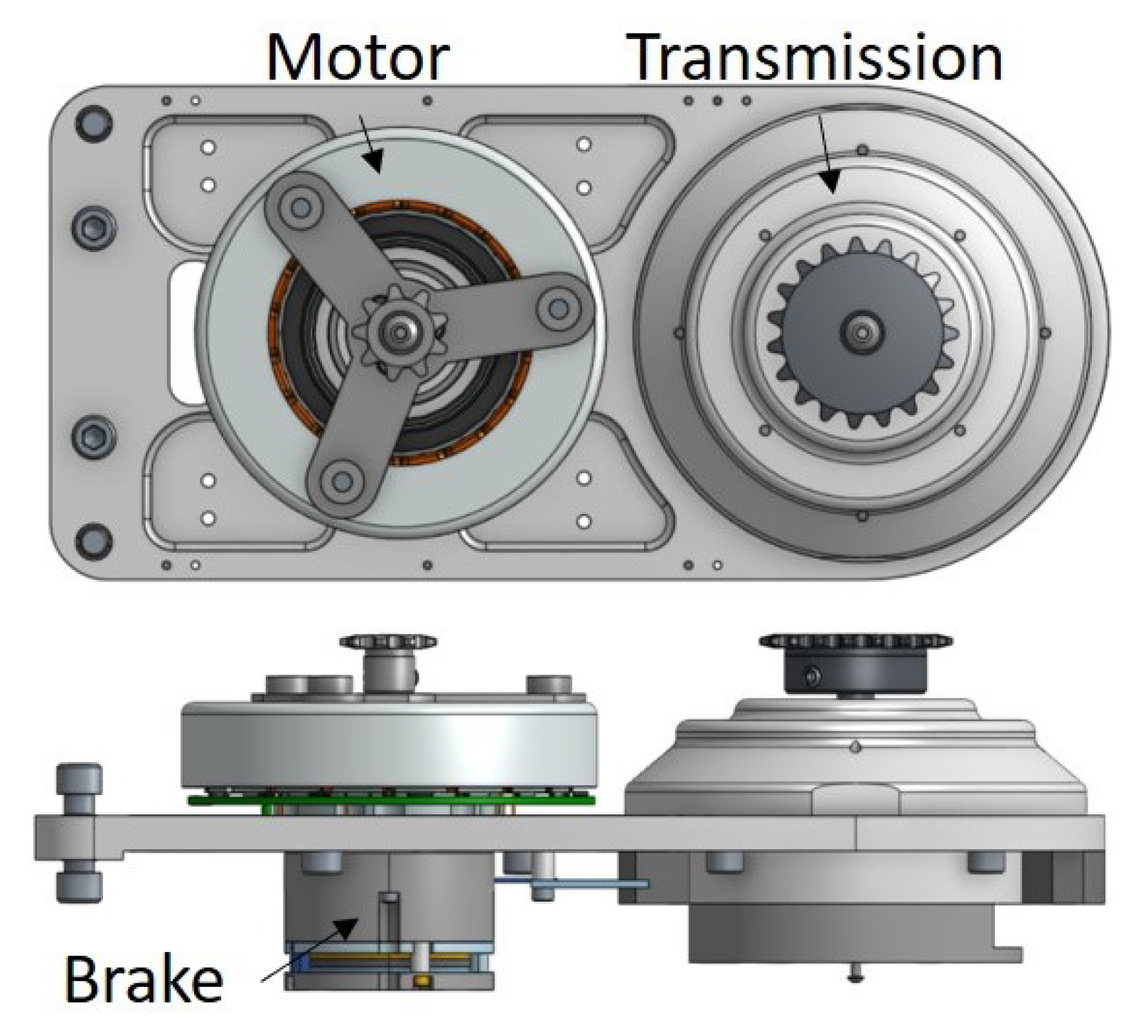
2.2.1. Motor/Brake Integration
2.2.2. Harmonic Drive Integration
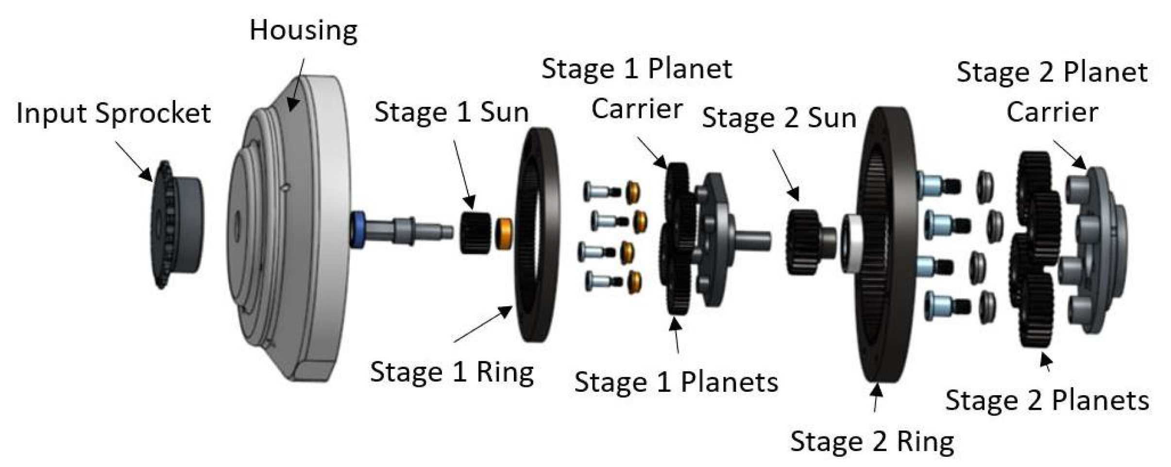
2.2.3. Planetary Gearbox Integration
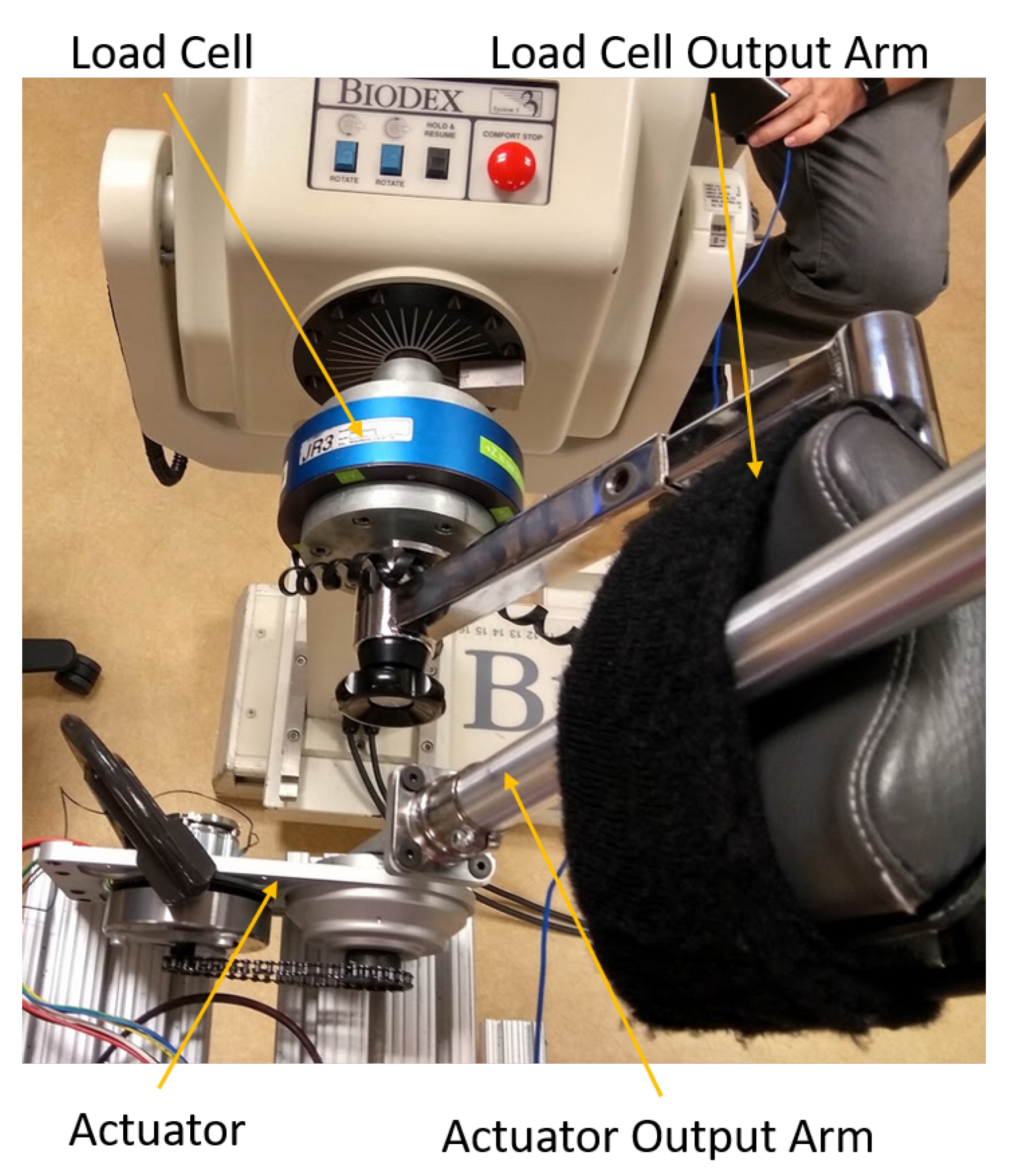
2.3. Actuator Evaluation
2.3.1. Isometric Torque
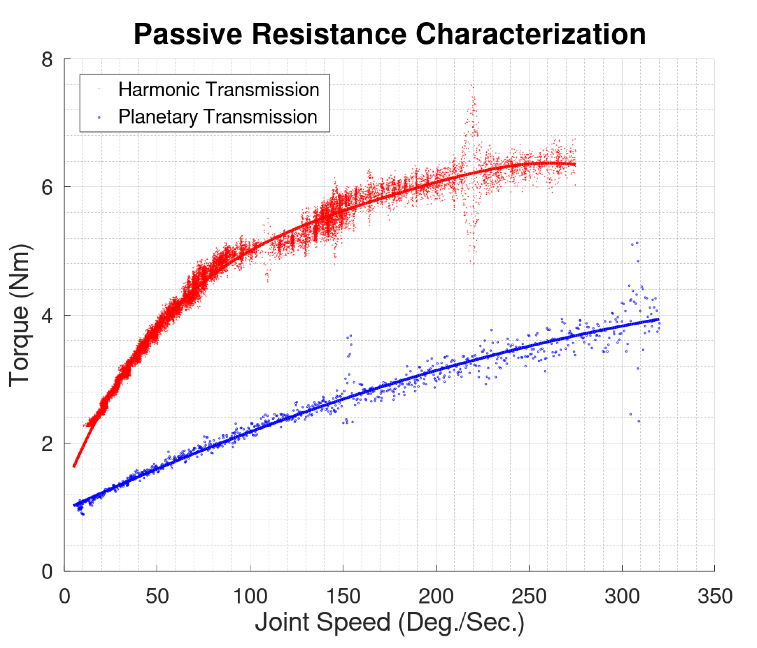
2.3.2. Passive Resistance
2.3.3. Net Torque Operating Envelope
2.3.4. Mechanical Efficiency
3. Results
3.1. Isometric Torque
3.2. Passive Resistance
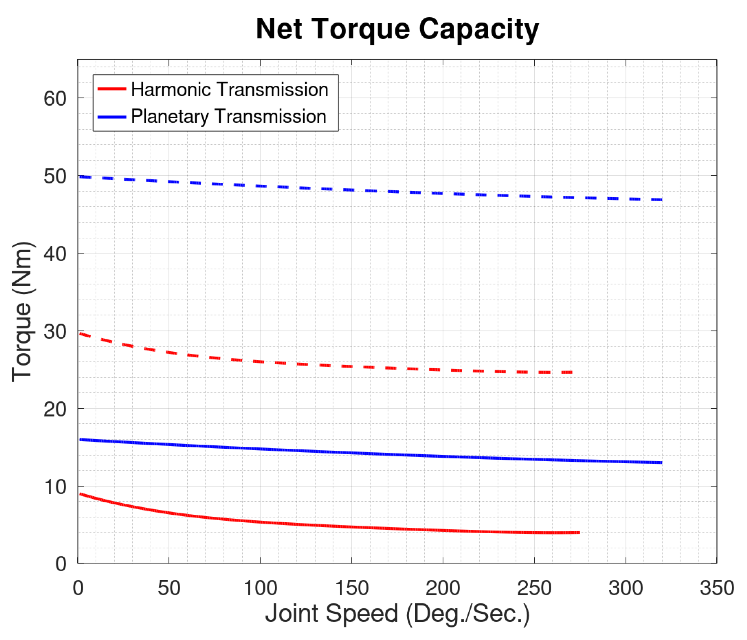
3.3. Net Torque
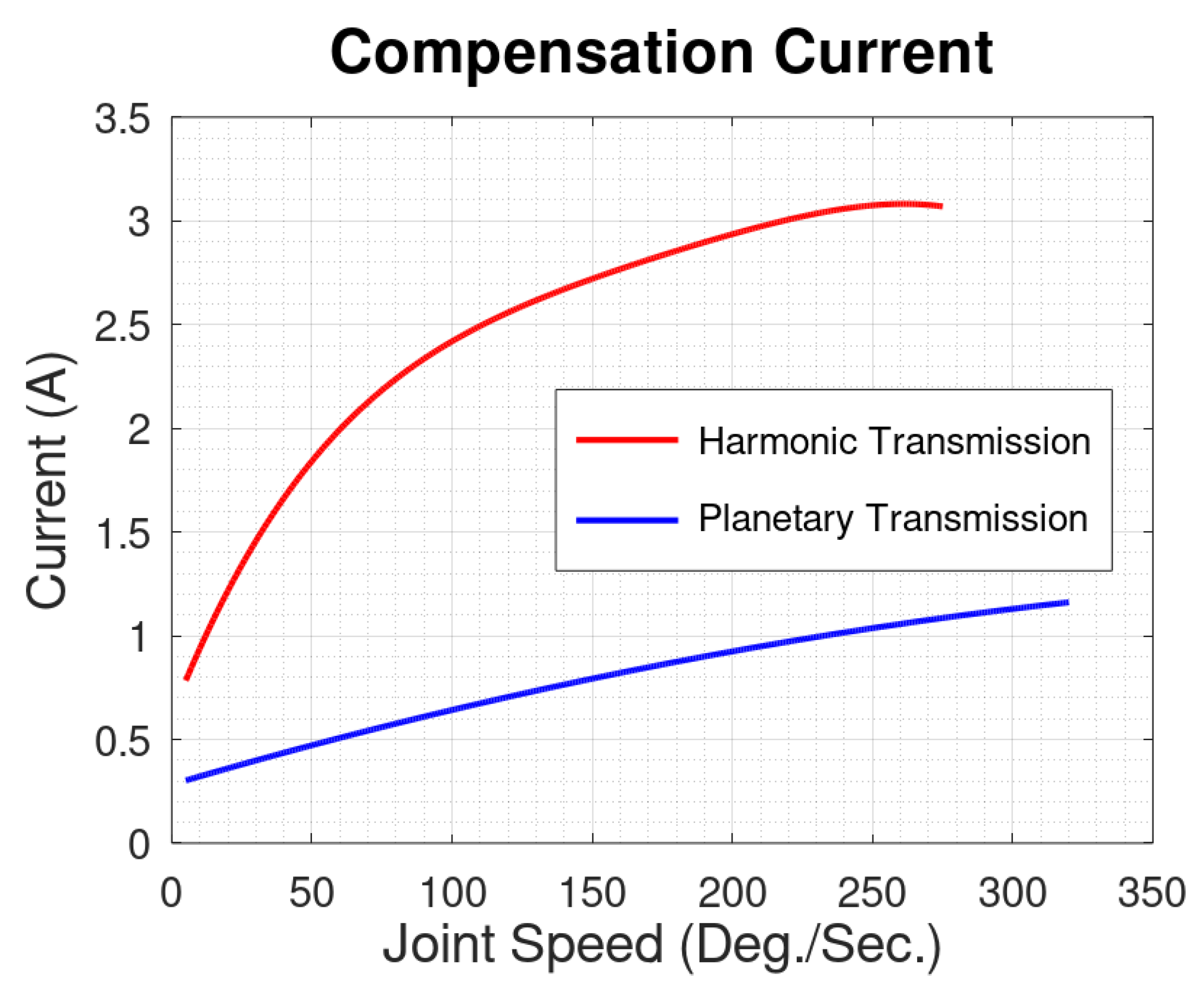
3.4. Compensation Current
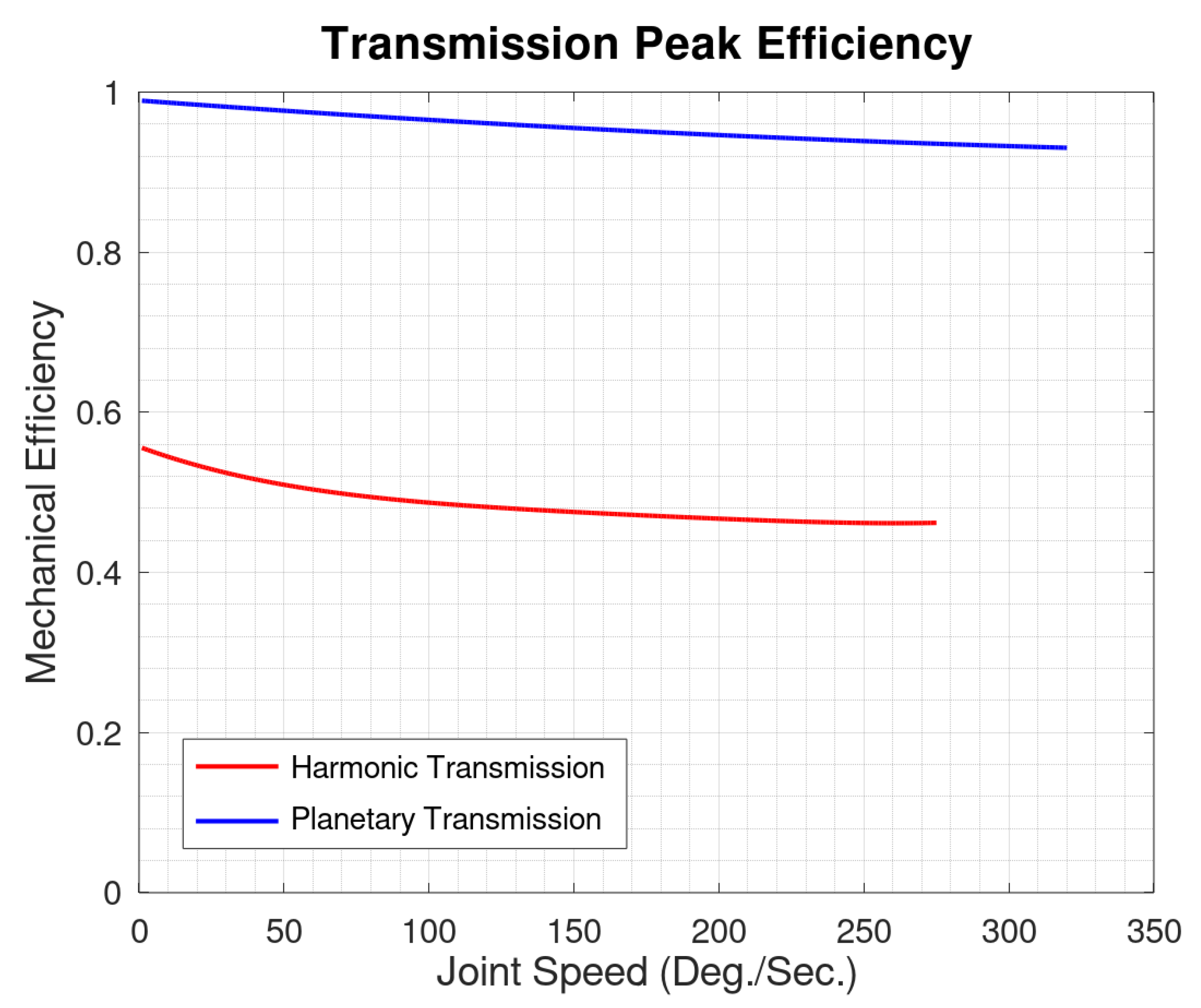
3.5. Mechanical Efficiency
4. Discussion
5. Conclusions
Author Contributions
Funding
Conflicts of Interest
Abbreviations
| SCI | Spinal Cord Injury |
| NMES | Neuromuscular Electrical Stimulation |
References
- National Spinal Cord Injury Statistical Center. Spinal Cord Injury Facts and Figures at a Glance 2020 SCI Data Sheet; Technical Report; University of Alabama at Birmingham: Birmingham, AL, USA, 2020. [Google Scholar]
- Brown-Triolo, D.L.; Mary, C.; Roach, J.; Nelson, K.; Triolo, R.J. Consumer Perspectives on Mobility: Implications for Neuroprosthesis Design. J. Rehabil. Res. Dev. 2002, 39, 659–670. [Google Scholar]
- Ditunno, P.L.; Patrick, M.; Stineman, M.; Ditunno, J.F. Who wants to walk? Preferences for recovery after SCI: A longitudinal and cross-sectional study. Spinal Cord 2008, 46, 500–506. [Google Scholar] [CrossRef] [PubMed]
- Anderson, K.D. Targeting Recovery: Priorities of the Spinal Cord-Injured Population. J. Neurotrauma 2004, 21, 1371–1383. [Google Scholar] [CrossRef] [PubMed]
- Kolakowsky-Hayner, S.A. Safety and Feasibility of using the EksoTM Bionic Exoskeleton to Aid Ambulation after Spinal Cord Injury. J. Spine 2013, 4, 1–8. [Google Scholar] [CrossRef]
- Hartigan, C.; Kandilakis, C.; Dalley, S.; Clausen, M.; Wilson, E.; Morrison, S.; Etheridge, S.; Farris, R. Mobility Outcomes Following Five Training Sessions with a Powered Exoskeleton. Top. Spinal Cord Inj. Rehabil. 2015, 21, 93–99. [Google Scholar] [CrossRef] [Green Version]
- Benson, I.; Hart, K.; Tussler, D.; van Middendorp, J.J. Lower-limb exoskeletons for individuals with chronic spinal cord injury: Findings from a feasibility study. Clin. Rehabil. 2016, 30, 73–84. [Google Scholar] [CrossRef] [PubMed]
- Puyuelo-Quintana, G.; Cano-De-La-Cuerda, R.; Plaza-Flores, A.; Garces-Castellote, E.; Sanz-Merodio, D.; Goñi-Arana, A.; Marín-Ojea, J.; García-Armada, E. A new lower limb portable exoskeleton for gait assistance in neurological patients: A proof of concept study. J. Neuroeng. Rehabil. 2020, 17, 1–16. [Google Scholar] [CrossRef]
- Buesing, C.; Fisch, G.; Shahidi, I.; Thomas, L.; Mummidisetty, C.K.; Williams, K.J.; Takahashi, H.; Zev Rymer, W.; Jayaraman, A. Effects of a wearable exoskeleton stride management assist system (SMA®) on spatiotemporal gait characteristics in individuals after stroke: A randomized controlled trial. J. Neuroeng. Rehabil. 2015, 12, 1–14. [Google Scholar] [CrossRef] [Green Version]
- Kawamoto, H.; Kamibayashi, K.; Nakata, Y.; Yamawaki, K.; Ariyasu, R.; Sankai, Y.; Sakane, M.; Eguchi, K.; Ochiai, N. Pilot study of locomotion improvement using hybrid assistive limb in chronic stroke patients. BMC Neurol. 2013, 13, 1–8. [Google Scholar] [CrossRef] [Green Version]
- Byl, N.N. Mobility training using a bionic knee orthosis in patients in a post-stroke chronic state: A case series. J. Med. Case Rep. 2012, 6, 1–5. [Google Scholar] [CrossRef] [Green Version]
- Maeshima, S.; Osawa, A.; Nishio, D.; Hirano, Y.; Takeda, K.; Kigawa, H.; Sankai, Y. Efficacy of a hybrid assistive limb in post-stroke hemiplegic patients: A preliminary report. Technical report. BMC Neurol. 2011, 11, 1–6. [Google Scholar] [CrossRef] [Green Version]
- Solomonow, M.; Baratta, R.; Hirokawa, S.; Beaudette, C. The RGO Generation II: Muscle Stimulation Powered Orthosis as a practical walking system for thoracic paraplegics. Orthop. Oct Nurs. Allied Health Database Pg 1989, 12, 1309–1315. [Google Scholar]
- To, C.; Kirsch, R.; Kobetic, R.; Triolo, R. Simulation of a Functional Neuromuscular Stimulation Powered Mechanical Gait Orthosis With Coordinated Joint Locking. IEEE Trans. Neural Syst. Rehabil. Eng. 2005, 13, 227–235. [Google Scholar] [CrossRef]
- Goldfarb, M.; Korkowski, K.; Harrold, B.; Durfee, W. Preliminary evaluation of a controlled-brake orthosis for FES-aided gait. IEEE Trans. Neural Syst. Rehabil. Eng. 2003, 11, 241–248. [Google Scholar] [CrossRef] [PubMed]
- Chang, S.; Nandor, M.; Li, L.; Foglyano, K.; Schnellenberger, J.; Kobetic, R.; Quinn, R.; Triolo, R. A stimulation-driven exoskeleton for walking after paraplegia. In Proceedings of the Annual International Conference of the IEEE Engineering in Medicine and Biology Society, EMBS, Orlando, FL, USA, 16–20 August 2016. [Google Scholar] [CrossRef]
- Nandor, M.; Kobetic, R.; Audu, M.; Triolo, R.; Quinn, R. A Muscle-First, Electromechanical Hybrid Gait Restoration System in People With Spinal Cord Injury. Front. Robot. AI 2021, 8, 645588. [Google Scholar] [CrossRef] [PubMed]
- Ha, K.H.; Quintero, H.A.; Farris, R.J.; Goldfarb, M. Enhancing stance phase propulsion during level walking by combining fes with a powered exoskeleton for persons with paraplegia. In Proceedings of the Annual International Conference of the IEEE Engineering in Medicine and Biology Society, EMBS, San Diego, CA, USA, 28 August–1 September 2012. [Google Scholar] [CrossRef] [Green Version]
- Alibeji, N.A.; Molazadeh, V.; Moore-Clingenpeel, F.; Sharma, N. A muscle synergy-inspired control design to coordinate functional electrical stimulation and a powered exoskeleton: Artificial generation of synergies to reduce input dimensionality. IEEE Control. Syst. 2018, 38, 35–60. [Google Scholar] [CrossRef]
- del Ama, A.J.; Gil-Agudo, A.; Pons, J.L.; Moreno, J.C. Hybrid FES-robot cooperative control of ambulatory gait rehabilitation exoskeleton. J. Neuroeng. Rehabil. 2014, 11, 27. [Google Scholar] [CrossRef] [PubMed]
- Kaminaga, H.; Amari, T.; Niwa, Y.; Nakamura, Y. Development of knee power assist using backdrivable electro-hydrostatic actuator. In Proceedings of the IEEE/RSJ 2010 International Conference on Intelligent Robots and Systems, IROS 2010—Conference Proceedings, Taipei, Taiwan, 18–22 October 2010; pp. 5517–5524. [Google Scholar] [CrossRef]
- Neubauer, B.C.; Nath, J.; Durfee, W.K. Design of a portable hydraulic ankle-foot orthosis. In Proceedings of the 2014 36th Annual International Conference of the IEEE Engineering in Medicine and Biology Society, EMBC, Chicago, IL, USA, 26–30 August 2014; Institute of Electrical and Electronics Engineers Inc.: Piscataway Township, NJ, USA, 2014; pp. 1182–1185. [Google Scholar] [CrossRef]
- Zhu, H.; Doan, J.; Stence, C.; Lv, G.; Elery, T.; Gregg, R. Design and validation of a torque dense, highly backdrivable powered knee-ankle orthosis. In Proceedings of the IEEE International Conference on Robotics and Automation, Singapore, 29 May–3 June 2017; Institute of Electrical and Electronics Engineers Inc.: Piscataway Township, NJ, USA, 2017; pp. 504–510. [Google Scholar] [CrossRef]
- Elery, T.; Rezazadeh, S.; Nesler, C.; Doan, J.; Zhu, H.; Gregg, R.D. Design and Benchtop Validation of a Powered Knee-Ankle Prosthesis with High-Torque, Low-Impedance Actuators. In Proceedings of the IEEE International Conference on Robotics and Automation, Brisbane, Australia, 21–25 May 2018; Institute of Electrical and Electronics Engineers Inc.: Piscataway Township, NJ, USA, 2018; pp. 2788–2795. [Google Scholar] [CrossRef]
- Goo, A.; Laubscher, C.A.; Farris, R.J.; Sawicki, J.T. Design and Evaluation of a Pediatric Lower-Limb Exoskeleton Joint Actuator. Actuators 2020, 9, 138. [Google Scholar] [CrossRef]
- Levai, Z. Structure and Analysis of Planetary Gear Trains. J. Mech. 1968, 3, 131–148. [Google Scholar] [CrossRef]
- Tuttle, T. Understanding and Modeling the Behavior of a Harmonic Drive Gear Transmission. Master’s Thesis, MIT, Cambridge, MA, USA, 1992. [Google Scholar]
- Andrews, A.W.; Chinworth, S.A.; Bourassa, M.; Garvin, M.; Benton, D.; Tanner, S. Update on distance and velocity requirements for community ambulation. J. Geriatr. Phys. Ther. 2010, 33, 128–134. [Google Scholar] [CrossRef]
- Bohannon, R.W.; Williams Andrews, A.; Michael Thomas, B.W. Walking Speed: Reference Values and Correlates for Older Adults. J. Orthop. Sport. Phys. Ther. 1996, 24, 86–90. [Google Scholar] [CrossRef] [PubMed]
- Bohannon, R.W. Comfortable and maximum walking speed of adults aged 20–79 years: Reference values and determinants. Age Ageing 1997, 26, 15–19. [Google Scholar] [CrossRef] [Green Version]
- Chang, S.R.; Kobetic, R.; Triolo, R.J. Effect of exoskeletal joint constraint and passive resistance on metabolic energy expenditure: Implications for walking in paraplegia. PLoS ONE 2017, 12, e0183125. [Google Scholar] [CrossRef] [PubMed] [Green Version]
- Farris, R.J.; Quintero, H.A.; Goldfarb, M. Preliminary evaluation of a powered lower limb orthosis to aid walking in paraplegic individuals. IEEE Trans. Neural Syst. Rehabil. Eng. 2011, 19, 652–659. [Google Scholar] [CrossRef] [PubMed] [Green Version]
- Kaminaga, H.; Tanaka, H.; Nakamura, Y. Mechanism and Control of Knee Power Augmenting Device with Backdrivable Electro-Hydrostatic Actuator; Technical Report; World Congress in Mechanism and Machine Science: Guanajuato, Mexico, 2011. [Google Scholar]
- Juvinall, R.C.; Marshek, K.M. Fundamentals of Machine Component Design, 4th ed.; John Wiley and Sons: Hoboken, NJ, USA, 2006; pp. 604–612. [Google Scholar]
- Xiao, Z.G.; Menon, C. Towards the development of a portable wrist exoskeleton. In Proceedings of the 2011 IEEE International Conference on Robotics and Biomimetics, ROBIO 2011, Karon Beach, Thailand, 7–11 December 2011; pp. 1884–1889. [Google Scholar] [CrossRef]
- Laubscher, C.A.; Farris, R.J.; Sawicki, J.T. Design and Preliminary Evaluation of a Powered Pediatric Lower Limb Orthosis. Proc. ASME Des. Eng. Tech. Conf. 2017, 58172, V05AT08A061. [Google Scholar] [CrossRef]
- Reyes, R.D.; Kobetic, R.; Nandor, M.; Makowski, N.; Audu, M.; Quinn, R.; Triolo, R. Effect of Joint Friction Compensation on a “Muscle-First” Motor-Assisted Hybrid Neuroprosthesis. Front. Neurorobot. 2020, 14, 588950. [Google Scholar] [CrossRef] [PubMed]
- Tuttle, T.D.; Seering, W.P. A Nonlinear Model of a Harmonic Drive Gear Transmission. IEEE Trans. Robot. Autom. 1996, 12, 368–374. [Google Scholar] [CrossRef]
- Marilier, T.; Richardt, J.A. Non-Linear Mechanic And Electric Behavior of a Robot Axis with a “Harmonic-Drive” Gear. Robot. Comput.-Integr. Manuf. 1989, 5, 129–136. [Google Scholar] [CrossRef]
- Kermani, M.R.; Patel, R.V.; Moallem, M. Friction identification and compensation in robotic manipulators. IEEE Trans. Instrum. Meas. 2007, 56, 2346–2353. [Google Scholar] [CrossRef]
- Hauschild, J.P.; Heppler, G.R. Control of harmonic drive motor actuated flexible linkages. In Proceedings of the IEEE International Conference on Robotics and Automation, Rome, Italy, 10–14 April 2007; pp. 3451–3456. [Google Scholar] [CrossRef]
- Levy, M.; Mizrahi, J.; Susak, Z. Recruitment, force and fatigue characteristics of quadriceps muscles of paraplegics isometrically activated by surface functional electrical stimulation. J. Biomed. Eng. 1990, 12, 150–156. [Google Scholar] [CrossRef]
- Xia, J.; Durfee, W.K. Analysis of small-scale hydraulic actuation systems. J. Mech. Des. Trans. ASME 2013, 135, 091001. [Google Scholar] [CrossRef] [Green Version]
- Zhu, Z.; Pan, Y.; Zhou, Q.; Lu, C. Event-Triggered Adaptive Fuzzy Control for Stochastic Nonlinear Systems with Unmeasured States and Unknown Backlash-Like Hysteresis. IEEE Trans. Fuzzy Syst. 2021, 29, 1273–1283. [Google Scholar] [CrossRef]
- Roman, R.C.; Precup, R.E.; Petriu, E.M. Hybrid data-driven fuzzy active disturbance rejection control for tower crane systems. Eur. J. Control. 2021, 58, 373–387. [Google Scholar] [CrossRef]


| Module | Pitch Diam. (mm) | Num. Teeth | Thickness (mm) | Gear Stress (MPa) | FOS | |
|---|---|---|---|---|---|---|
| Stage 1 Sun | 0.5 | 12 | 24 | 5 | 119.8 | 2.6 |
| Stage 1 Planet | 0.5 | 19 | 38 | 5 | 105.4 | 2.9 |
| Stage 1 Ring | 0.5 | 50 | 100 | 5 | 90.5 | 3.4 |
| Stage 2 Sun | 0.8 | 19.2 | 24 | 8 | 141.3 | 2.2 |
| Stage 2 Planet | 0.8 | 22.4 | 28 | 8 | 135.3 | 2.3 |
| Stage 2 Ring | 0.8 | 64 | 80 | 8 | 109.2 | 2.8 |
| Actuator | Technology Used | Mass (kg) | Max Speed (deg/s) | Max Torque (Nm) | Max Passive Resistance (Nm) | Peak Efficiency |
|---|---|---|---|---|---|---|
| Planetary | 2 Stage Planetary + chain | 2.1 | 330 | 50.9 | 4 | 96% |
| Harmonic | Harmonic Drive | 2.1 | 270 | 31.1 | 6.5 | 54% |
| Nandor et al. [17] | Harmonic Drive | 2.2 | 400 | 36 | 8.4 | N\A |
| Neubauer et al. [22] | Electro-hydraulic | 3.5 | 250 | 90 | N\A | 45% |
| Kaminaga et al. [21] | Electro-hydraulic | 1.1 | 330 | 30 | 4.8 | N\A |
| Goo et al. [25] | 2 stage belt/chain | 0.6 | 370 | 21.1 | 0.33 | N\A |
| Zhu et al. [23] | belt + planetary | 1.2 | 480 | 60 | 8 | 90% |
Publisher’s Note: MDPI stays neutral with regard to jurisdictional claims in published maps and institutional affiliations. |
© 2021 by the authors. Licensee MDPI, Basel, Switzerland. This article is an open access article distributed under the terms and conditions of the Creative Commons Attribution (CC BY) license (https://creativecommons.org/licenses/by/4.0/).
Share and Cite
Nandor, M.J.; Heebner, M.; Quinn, R.; Triolo, R.J.; Makowski, N.S. Transmission Comparison for Cooperative Robotic Applications. Actuators 2021, 10, 203. https://doi.org/10.3390/act10090203
Nandor MJ, Heebner M, Quinn R, Triolo RJ, Makowski NS. Transmission Comparison for Cooperative Robotic Applications. Actuators. 2021; 10(9):203. https://doi.org/10.3390/act10090203
Chicago/Turabian StyleNandor, Mark J., Maryellen Heebner, Roger Quinn, Ronald J. Triolo, and Nathaniel S. Makowski. 2021. "Transmission Comparison for Cooperative Robotic Applications" Actuators 10, no. 9: 203. https://doi.org/10.3390/act10090203