Abstract
Electro-hydrostatic actuators (EHAs) are expanding their application fields due to their combined advantages of electric and hydraulic actuation. However, the control performance, the weight, and the efficiency turn out to be more challenging requirements when the EHA power level increases to over 30 kW. Therefore, a preliminary design dedicated to trading off the system-level EHA performance based on multi-domain coupling analysis is necessary considering the comprehensive performance requirements and the parameter uncertainties. However, the existing methods are deficient in responding to all these design challenges. In this paper, an EHA preliminary design method is proposed to achieve the optimum system-level performance with robustness. First, the design parameters are analyzed and selected. Second, an optimization design of EHAs is realized by developing multi-disciplinary performance simulation models. The robustness is also considered during the optimization design. Third, the optimization results are evaluated by a specifically built EHA model, which realizes high fidelity than the models used for optimization. As a result, the general high-power EHA requirements are fully considered during the preliminary design and an optimum EHA performance is achieved. The proposed method is demonstrated in a design case of a 30 kW EHA for aerospace applications, which achieved the optimum performance of 8 Hz bandwidth and 69.92 kg weight. The preliminary design results also outline the input information for the following detailed design. Therefore, the proposed method demonstrated its applicability for delivering robust EHA design results for engineering applications.
1. Introduction
Electro-hydrostatic actuators (EHAs) are a new generation of hydraulic actuators that utilize electric motor-pump combinations to directly drive cylinders. They hereby combine the advantages of electric and hydraulic actuation and result in omitting the throttling losses, simplifying the system topology, and facilitating integrated as well as modular designs. The aerospace industry first explored the EHA concept in the 1980s [1] and already started the applications in recent aircrafts, e.g., A380 and F35. The EHA benefits also attract attentions from other industry fields. Growing EHA research and development efforts are invested in industrial fields such as heavy-duty mobile machinery [2], robots [3], and subsea machines [4]. The indicated spreading of the EHA application also calls for higher power capacity (>30 kW) [5,6]. It is important to note that the constraints such as weight, thermal management, and dynamic performance become more challenging for high-power EHAs due to the utilized high-power motor-pump combinations and the associated power electronics. Therefore, a thorough system-level performance compromise is necessary for the high-power EHAs to fulfill the challenging requirements while keeping other performance optimum. For instance, the motor-pump maximum rotational speed is a critical EHA parameter, which should be regulated based on applications due to its significant effects on several performance criteria, e.g., weight, efficiency, and dynamic performance. But it cannot be determined by straightforward calculations, which are deficient to consider all the related factors. Instead, only by involving it in the system analysis with other parameters and all the primary performance requirements, can the maximum motor-pump rotational speed be decided for best using the component resources. Otherwise, any absence of the parameters or performance requirements in the system-level design would result in a redesign of the EHA or even no feasible designs. These design challenges arising from the high-power EHAs demand a comprehensive system design method that can deal with the conflicting requirements and the coupling characteristics.
The standard VDI 2206 specifies the V-shape design process of mechatronic products such as EHAs [7]. It emphasizes the significance of the system design step for achieving satisfying product performance. The system design consists of the conceptual design and the preliminary design. The conceptual design outlines the functional blocks of the products while the preliminary design determines the sizing of each block for fulfilling the system-level performance requirements. A specific preliminary design method is needed for the high-power EHAs as the multidisciplinary coupling and the challenging requirements both need an integral system-level analysis. However, the notable uncertainties at the preliminary design stage pose difficulties in acquiring accurate parameters. The uncertainties also cause problems in the performance prediction of the design options. Therefore, special attention is needed for the parameter manipulation and the design robustness.
Abundant research has been performed for resolving these challenges of the preliminary design of EHAs or similar products. Andersson presented an optimization design structure for EHAs [8,9,10]. The simulation models, the design structure matrix, the relationship matrix, etc., are proposed to realize the optimization design. A robust design approach based on design of experiments (DOE) is also discussed. But it is an early stage concept, which only involves a simplified characteristics analysis. Wu proposed a simulation-based optimization design of the EHA, which considers the dynamic performance, weight, efficiency, and stiffness [11]. However, in the presented work the simulation parameter handling of the optimization task is not fully illustrated. Budinger performed continuous research on electromechanical actuator (EMA) preliminary design, where the parameter handling, the modeling approach, and the design process are all surveyed in-depth [12,13]. However, limited attention is put on uncertainties. Proposed by Arriola, the preliminary EHA design method specifically considers parameter handling without dealing with the control performance and uncertainties [14]. Chakraborty suggested the preliminary design of the EHA/EMA-based electrified flight control actuation system [15], which is simplified and put emphasis on the upper-level flight control system. Roos put forward the design method of mechatronic servo systems involving both mechanical and control performance [16], whereas the multi-objective handling method is not demonstrated. Pettersson reported an optimization design method for the drive trains of industrial robots. The method involves mechanical performance, life, cost, etc., while the essential control performance is not included [17]. Lei and Shi developed an electric drive design method with special consideration to design robustness [18,19]. Gang, Gerada, and Kim all proposed specific calculation models for the electric motor characteristics [20,21,22,23]. Budinger, Guo, and Kreitz suggested analysis methods for parameter sensitivity or uncertainties [24,25,26]. Although [18,19,20,21,22,23,24,25,26] contribute key techniques to the preliminary design methods, the integral solution was still absent. If applied directly to engineering applications, they are not capable of covering all the conflicting requirements, achieving enough design robustness, or balancing the calculation cost for high-power EHAs. An optimization design technique of the high-power EHA was proposed by the authors [27]. Specific calculation models and the optimization process were presented for meeting the preliminary design requirements. But the design parameter handling, the characteristics analysis regarding thermal, reliability, and life, and the design robustness were not considered, which limits its applicability.
Therefore, this paper addresses the previously mentioned limitations of the existing methods by developing an integral solution for the preliminary design of the high-power EHAs. The abilities for handling the full requirements, the parameter uncertainties, and the comprehensive performance evaluation are specifically considered. As a result, the proposed method seamlessly links the conceptual design and detailed design by sizing the system-level parameters with optimum EHA performance. A 30 kW aerospace EHA with multiple challenging requirements is selected as the study case. The general EHA requirements, e.g., the power capacity, the control performance, the life and reliability, are all involved in the design. The design parameters with inherent uncertainties are sized. So, practical input for the following detailed design is obtained. The proposed method enables better usage of the current technical resources for a strengthened EHA performance. The design time can also be cut owing to the use of modular and reusable calculation models as well as optimization algorithms. The high-power EHA applicability is hereby improved due to the enhanced performance and shortened design time.
The remaining content of the paper is organized as follows: Section 2 introduces the newly proposed EHA preliminary design process; Section 3 illustrates the design parameter analysis method, including the parameter selection and the automatic parameter generation; Section 4 presents the calculation models for the different EHA characteristics, of which the results are used as the objectives and constraints; Section 5 explains the optimization and design verification methods; Section 6 presents the design results and the associated discussion; Section 7 draws the conclusion.
2. The Preliminary Design Process of High-Power EHAs
The preliminary design starts with the given design inputs: the conceptual design results and the requirements of the EHA. Subsequently, the system-level parameters are sized, and the system-level performance is accordingly achieved. The system-level parameters are the specifications of the utilized components, either customized or off-the-shelf. So, they will be used as the component requirements in the following detailed design stage [7]. The system-level performance is that of responding to the design requirements. For high-power EHAs, the parameters and the characteristics need more delicate handling due to the arising performance challenges and the highly coupled multidisciplinary effects, e.g., the lower dynamic response, the higher heat generation. A preliminary design process of the electro-variable displacement pump was briefed in [28] while only the final design verification step was detailed. Here the design process is upgraded for high-power EHAs, as illustrated in Figure 1. The complete process is elaborated in the following texts, especially the upgraded procedures responding to the previously clarified design issues, e.g., the comprehensive performance evaluation, the parameter uncertainties, and the multidisciplinary coupling considerations.
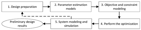
Figure 1.
The preliminary design process of high-power EHAs [28].
The preliminary design outputs the sized system-level parameters as the design results. So, Step 1 selects the design parameters according to the performance requirements. The design parameters and the performance requirements are also classified in Step 1, which clarifies the tasks for the following design steps. The design parameters are classified into active ones and non-active ones. Only the active parameters are directly regulated during the preliminary design. The non-active parameters are usually decided under the component constraints rather than freely picked. This parameter manipulation enables a more efficient component sizing flow [29]. The requirements are classified into optimization objectives and constraints, which will be further dealt with in the following optimization design. Step 2 develops the specific estimation models for the non-active parameters based on the current component performance envelope. Step 3 develops the calculation models for the optimization objectives and constraints. The preliminary design is better to involve a system-level optimization to enhance the performance. Due to the multidisciplinary and multi-objective features of EHA, specific models for performance evaluation are necessary. Step 4 performs the robust optimization design, which adopts the tools and models from the previous steps. Step 5 builds a comprehensive EHA model to verify the optimization results. The EHA model in Step 5 is more accurate and complete than the models in the optimization design. The combined Step 4 and Step 5 can facilitate more robust and reliable preliminary design results. If the verification in Step 5 fails, the whole design process needs to be iterated, wherein the design process should be rectified according to the failures. The proposed EHA design method is detailed step by step in the following sections based on a study case of a 30 kW aerospace EHA.
3. Design Preparation and Parameter Estimation
The inputs for preliminarily designing a 30 kW EHA are shown in Figure 2 and Table 1, which are the conceptual design results and the performance requirements, respectively. The EHA electronics (1 in Figure 2) are installed separately, which is out of the scope of this paper. The remaining components need to be sized subject to the requirements in Table 1, i.e., the preliminary design task of the 30 kW EHA. The design preparation and parameter estimation are demonstrated in this section using this 30 kW EHA design case.
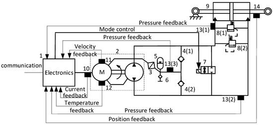
Figure 2.
The EHA schematics from the conceptual design [27]. (1) electronics; (2) electric motor-pump unit; (3) filter; (4) check valves; (5) reservoir; (6) filling port; (7) mode control valve; (8) relief valves; (9) cylinder; (10) current sensor; (11) rotational speed sensor; (12) temperature sensor; (13) pressure sensors; (14) displacement sensor.

Table 1.
The system-level performance requirements of a 30 kW EHA [27].
3.1. Design Preparation
The parameters to be sized in the preliminary design should be selected first. The parameters are those for specifying the components and are able to steer the required performance of the EHA. So, a parameter selection method is proposed by matching the component specifications with the EHA requirements, which is modified from the relationship matrix method [8]. The method is demonstrated in Table 2 taking the permanent magnet synchronous motor (PMSM) as an example. The EHA performance requirements are listed in the top row. The general specifications of the component are listed in the left column. Then, a bi-directional check is performed. First, match each component parameter to the listed requirements. Mark a dot at the crossed cell if the parameter affects the corresponding requirement. Second, check each requirement in the top row by considering what other parameters that are not considered in the first check can affect it. Then, the requirements can be examined again, especially those that were not matched with any design parameters (e.g., the stroke requirement was not matched with any parameters in the first check, it will be examined again in the second check for confirming if other parameters should be matched to it). Moreover, this check can help to supplement the parameters that are not usually listed in the component specifications. As a result, the parameters that have dots in their row are selected as the design parameters of the analyzed components. By performing this method for each component, all the design parameters can be found.
Table 2.
The design parameter selection table of the EHA—the electric motor case.
Next, the parameters and the requirements are classified for being used in the following design steps. The requirements that bring additional values when more strictly set are classified as optimization objectives. The requirements that do not add significant values when more strictly set are classified as constraints. Under this classification, the optimization design can improve the overall competence of EHAs. In this study, mass and efficiency are set as the optimization objectives, which are beneficial attributes for aerospace applications.
As for the parameters, they are not necessarily to be all self-designed in the preliminary design. Moreover, complete parameter adjusting is not possible due to their dependency. So, they are classified into active parameters and non-active parameters [13]. The active parameters are actively defined while the non-active ones are automatically generated. The active parameters are representative of the components or directly reflect the requirements (e.g., the maximum torque of the electric motor reflecting the maximum EHA force). Based on the active parameters, the non-active parameters are estimated automatically by the estimation models. Using the non-active parameter category means presuming some design rules for the components. For example, the scaling law estimation methods assume the geometry and material similarity of the components. This can result in the weakening of the design freedom and hereby a less optimized component design. So, specific analysis for the effects of using non-active parameters and the associated estimation models is important. In this paper, the non-active parameters are estimated based on the state-of-the-art components, which promotes a balance between the design difficulties and the performance optimum. The parameter classification for this estimation method is illustrated first.
Considering the electric motor, the authors choose Parker HKW servomotors [30] as the reference components. The servomotor specifications adopt supply voltage V0m, stator diameter D0m, stator length L0m, and power level P0m for defining a motor model. Pick out the corresponding parameters in Table 2 for being considered as the active parameters of the electric motor, i.e., supply voltage V0m, max torque Tmaxm, and base speed ω0m. Next, as previously clarified, the component parameters reflecting the performance requirements should also be considered active parameters. So, stall torque T0m and max speed ωmaxm, reflecting EHA continuous force and max velocity, respectively, are also selected as the active parameter candidates. The pre-identified five parameters need to be examined again. Supply voltage V0m is identified as an independent defining parameter of the servomotor. Whereas max torque Tmaxm couples with stall torque T0m. Max torque Tmaxm within the HKW servomotor specifications is more regular than stall torque T0m, indicating the priority of Tmaxm. The max speed ωmaxm of the HKW servomotor is shown to be a hardware-based parameter without considering control limitations. It has to be specifically dealt with rather than used for governing other parameters. Although base speed ω0m reflects EHA continuous velocity, max current Imaxm is selected instead as it shows to be the driving parameter of base speed ω0m (Imaxm has more regular values and correlates with ω0m). Therefore, supply voltage V0m, max torque Tmaxm, and max current Imaxm are finally selected as the active parameters of the electric motor. It is worth noting that max current Imaxm is used internally during the preliminary design for parameter estimation convenience, the design outputs should be converted to base speed ω0m for keeping consistent with Table 2. The parameters of other components are also classified using this method. The further manipulation of the component parameters for estimation is illustrated in the next sub-section.
3.2. Parameter Estimation Models
The non-active parameters can vary under the same active parameters due to different design considerations of the components. The ideal solution is involving a sub-optimization design of each component in the preliminary design with the system-level requirements as the optimization objectives. Then the optimum non-active parameters of each component are designed. But this will result in an unacceptable optimization task. Estimation methods costing light calculation and developing efforts should be used. This paper proposes a method for estimating the non-active parameters using the state-of-the-art components in the same application field as references.
An aerospace product usually customizes its major components while utilizing off-the-shelf options for its auxiliary components. This is because the major components significantly affect the product performance, so the high customization cost is deserved. But the benefits of using a customized auxiliary component may not finally pay back. Therefore, the non-active parameters of the auxiliary components can be estimated by directly searching for the closest off-the-shelf component in the database. The main concern of parameter estimation falls within the major components.
The existing components in similar application fields are the maturely optimized results. Using them as reference components can guarantee the advantages of state-of-the-art technology. The EHA preliminary design will iteratively evaluate different component selections, which needs the parameters of each selected component. The scaling laws [29,31] attract a lot of attention for estimating the parameters of the customized major components. But the assumed geometry similarities cannot assure the optimum component performance, which hereby harms the final EHA performance. This paper proposed a modified scaling law method as well as the empirical function method, which can estimate the parameters of a better-optimized component. Continuing with the electric motor example, first, due to the certain advantages of the high voltage, V0m is assigned with the onboard supply voltage, 540 VDC. The other two active parameters, max torque Tmaxm and max current Imaxm will be actively adjusted during the optimization design. Estimation models need to be developed for the non-active parameters.
The HKW servomotor specifications show that one servomotor model is distinguished from others by max torque Tmaxm and max current Imaxm. However, customized electric motors beyond the existing HKW motor models will also emerge during the optimization design. The customized max torque Tmaxm is achievable through non-unique solutions (one value of Tmaxm is achievable by different length/diameter ratios of the servo motors). Therefore, the ratio im has to be specified for obtaining a deterministic motor design with respect to one Tmaxm. Consequently, Tmaxm, Imaxm, and im are the minimum parameters for specifying one motor selection and are adopted for the non-active parameter estimation. For clarity, im is designated as an assistive parameter.
First, the power functions are considered for establishing the relations between the active parameters and the estimated non-active parameters, which are modified from the scaling laws [24]. The function identification is realized by fitting the existing component model parameters to the considered power functions. It is not necessary to fit the parameters of all the existing models to the functions. The scope of the used parameters for the function identification is decided by covering the optimization space. For example, the EHA design case of Table 1 can be covered by electric motors ranging from max torque Tmaxm 25 Nm to 70 Nm, which is estimated by static power transmission calculation. The orders of the power functions are selected based on the balance between accuracy and simplicity. Two exemplified identified estimation functions that are appropriate for the motor non-active parameters are:
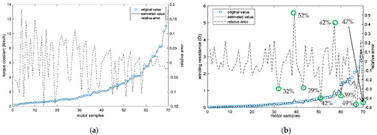
Figure 3.
The original parameter values and the estimated parameter values. (a) The original and estimated values of torque constant Ktm. (b) The original and estimated values of winding resistance Rm.
As for efficiency, service life, and reliability, they are usually specified as constant for a series of components. So, the relevant parameters are considered the same despite the component sizes being adjusted during the preliminary design. It is worth noting that these parameters are usually dependent on the working conditions, e.g., the pump efficiency depends on the working pressure, speed, etc. Therefore, they can be fitted to empirical functions with the working conditions as variables. Then the empirical functions are attached to the corresponding models and the instant values can be obtained during the simulation. E.g., the piston pump efficiency is modeled using the Schlösser functions [32]. For modeling the heat transfer coefficients/thermal resistance, the thermal transfer-related dimensions need to be estimated based on a reference structure first. Then the heat transfer coefficients/thermal resistance are modeled using the empirical functions [28]. These functions are also working condition dependent.
More and more parameter estimation techniques are being proposed. The emerging machine learning-based estimation models can be considered to further improve the estimation accuracy [33]. The preceding illustration of the parameter classification and estimation procedures is concluded in Figure 4. Sometimes a series of mature components may not be available for building the parameter estimation models. The variable power law meta-model (VPLM) [24] can be used for this situation. But it is better to request a series of design examples from the component manufacturer for building the previously proposed estimation models. This is better for making use of the component expertise to assist in a better EHA design.
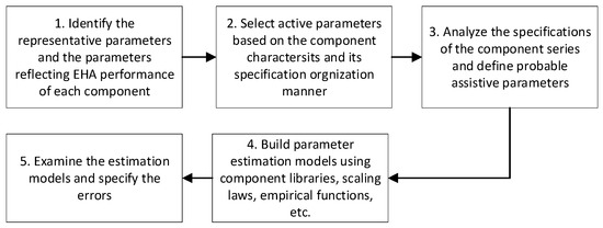
Figure 4.
The classification and estimation procedures of the component parameters.
4. Calculation Models of the Objectives and Constraints
The models for calculating the specified objectives and constraints in Section 3.1 need to be established for realizing the EHA optimization design. The models should be calculation efficient to enable the massive evaluation of the objectives and constraints with an acceptable time cost. The models merely rely on the previously studied design parameters to comply with the present design task. Moreover, considering the intrinsic multi-disciplinary coupling characteristics of the EHA, the calculation models should support obtaining a consistent evaluation result of the EHA performance [34]. Therefore, compared to the models purely for simulation analysis, the calculation models here should be built with special considerations on the usability for the optimization design. This paper upgrades the previously proposed method [27] by organizing the calculation models based on the complete design requirements.
First, models for the two objectives need to be built. The estimation models for individual component mass can be built according to Section 3.2, either through component libraries or specifically developed functions. Then the EHA mass is obtained by adding the component mass together [27,28]. The efficiency is modeled by the consumed energy under specified duty cycles [27,35]. The efficiency calculation model also relies on the estimated parameters questioned in Section 3.2.
Calculation Models for the Constraints
The constraints assure the optimized EHA parameters meet the design requirements and fall within performance boundaries. Therefore, not only the design requirements other than the objectives but also the parameter space boundaries are modeled as constraints. The constraint modeling objects are identified from the design requirements and the component specifications. Regarding the control-related requirements, the transfer function is used for realizing the corresponding constraints [27]. Regarding the working temperature requirements, the design task is to prevent overheating when the EHA works under tough conditions. At the present optimization phase, the main action responding to this task is to minimize the EHA losses, which act as heat sources. This is already realized by the previous efficiency optimization objective. As for the heat dissipation function, which is an add-on design that does not affect the system-level optimum, it will be resolved in the following design steps.
Regarding the power capacity-related requirements (force and velocity), corresponding constraint models should be built for each component. For the cylinder and the pump, the Bernoulli equation and the continuity equation are used for the constraint models driven by the force and velocity requirements [36]. For the electric motor, the power capacity-related constraints should be modeled under the field weakening control method as it is a necessary motor control scheme to exploit the EHA performance potential:
where ηmT is the torque efficiency of the electric motor, Tm is the output torque of the electric motor, F0c is the required continuous force of the EHA, max(Tm) is the maximum output torque of the electric motor realized by field weakening control under the continuous force condition, is output pressure of the pump, is the rated pressure of the pump, is the rated pressure of the reservoir, is the pressure loss coefficient, is the pump displacement. Regarding the lifetime and reliability requirements, first, the lifetime is calculated based on the pump wear life as in Equation (5), which is the weakest part of the EHA. Then the EHA reliability after working the required lifetime (10,000 h) is evaluated by Equation (6) [28].
where is the mean load of the pump under the specified EHA duty cycle using the rainflow counting [37]; m is the quantity of the pump load cycles that are counted; is the quantity of the ith cycle; is the quantity of ith cycle that can run out of the pump life; is the EHA duty cycle duration, from which the m pump load cycles are identified; α and β are the experimental constants, is the reference reliability after working out the lifetime of the EHA [38], and is the required EHA lifetime. Equations (6) and (7) indicate that the lifetime and reliability highly depend on the specified duty cycle. It is worth noting that Ni is obtained by fitting load stress to the linear log-log S-N curve of the pump, which is established using the maximum load-life data and nominal load-life data, as illustrated in Figure 5. The log-log S-N curve can be improved when more pump lifetime data become available.
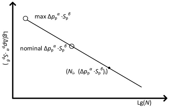
Figure 5.
The Ni identification using the linear log-log S-N curve of the pump.
The performance limits are also modeled as constraints in case the following optimization tends to a result that is unlikely to be realized based on the available technical measures. One exemplified constraint model is the limit of the maximum motor current :
where and are the upper and lower bound of the motor maximum current, respectively. Equations (7) and (8) are set as constraints under the selected motor torque Tmaxm and motor length/diameter ratio , which are fitted to the existing HKW motor data. By adding these kinds of constraints, the optimized parameter results are feasible under the conditions of manufacturing the referenced components.
As clarified before, the calculation models of the objectives and the constraints still need to deal with the multidisciplinary coupling, i.e., the variable coupling between different calculation models. By using parameter estimation tools and the organization of the calculation models, a unidirectional calculation sequence is obtained for the previously developed models, which is illustrated by the design structure matrix (DSM) in Figure 6. The bidirectional variable coupling is hereby avoided, and the multidisciplinary coupling is realized in a calculation-efficient way.
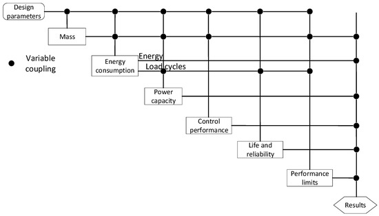
Figure 6.
The design structure matrix of the calculation models of the objectives and constraints.
5. Optimization Design and Verification
The optimization design enhances the system-level performance of the EHA, which is beneficial for bringing EHAs into real applications. The optimization design is basically exploring better combinations of the design parameters by comparing and iterating the potential design parameters, which are evaluated by the calculation results of the objective and constraint models. Once a set of design parameters are defined, they are fed to the calculation models in Section 4. Then the parameter evaluation results are obtained by running the calculation sequence in Figure 6. The task of this section is to embody the design parameter iteration scheme based on the optimization methodology. The scheme should be calculation efficient and robust to uncertainties in order to qualify its applicability. This paper proposes a robust EHA optimization method. The optimization results are subsequently verified using an analysis method adapted from [28].
Owing to the high calculation efficiency of the previously developed calculation models and sequence, the population optimization algorithms requiring massive evaluations can also be utilized, which is beneficial for solving the complex design optimization problem. Moreover, multi-objective optimization needs to be used as the present optimization involves two objectives (mass and efficiency). Therefore, the multi-objective genetic algorithm (NSGA-II) is selected. As clarified in Section 2, the optimization design primarily aims to find the potential optimum design solution rather than assuring the final preliminary design results. Therefore, the optimization design focuses more on the attributes that affect the optimum. That is to say, not all the design requirements are involved, e.g., the previously mentioned temperature evaluation is not included. Accordingly, the complete design requirements will be examined in the next step, i.e., system modeling and simulation.
As a result, the optimization design flowchart illustrated in Figure 7 is suggested. The optimization variables are maximum motor torque Tmaxm, maximum motor current Imaxm, pump displacement Dp, cylinder diameter Dc, and the motor length/diameter ratio im, which are decided in Section 3. These five parameters specify the customized components of the EHA. The other components in Figure 2 are embodied using off-the-shelf components, of which the models are directly decided based on the EHA pressure and flow. So, the models are imported into the optimization directly. Then, the estimation models and calculation models are called in turn to sequentially generate the non-active parameters and calculate the objectives and constraints. Then the multi-objective GA algorithm coordinates the optimization iteration. At last, the optimized design parameters are obtained.
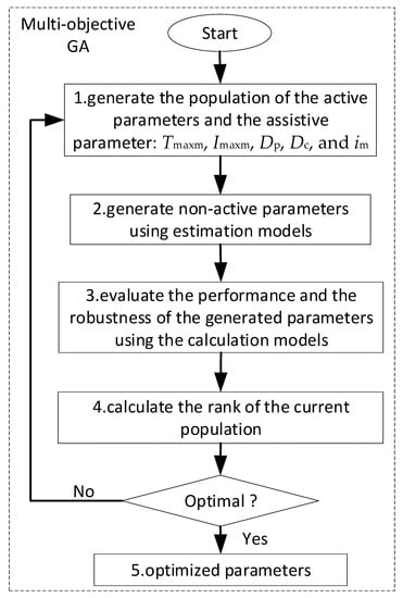
Figure 7.
The suggested optimization design flowchart of the EHA.
The optimization design robustness is resolved in step 3 of the flowchart. Each set of design parameters generated during the optimization possesses uncertainties, either due to the manufacturing tolerances or the estimation errors. Based on the component manufacturing experiences or the previous parameter estimation process, the distribution of each parameter can be specified after the parameter is generated. E.g., the motor winding resistance uncertainties are defined by the uniform distribution U(0.85∙Rm,1.15∙Rm) due to its 15% average estimation error. Then the design for 6σ method based on Monte Carlo analysis is used for achieving the optimization robustness [18]. One generation of the design parameters from steps 1 and 2 with distribution information is delivered to step 3. For one set of the design parameters Xi, an amount of the design parameter combinations is sampled from the parameter distributions. All the sampled parameter combinations are evaluated using the calculation models. The distribution of each objective or constraint is identified based on the calculation results of the sampled parameters. The 6σ confidence level values of the objectives and constraints ( and ) are derived as the evaluation results of the parameter set Xi, which are returned to the optimization task:
where is the objective; is the constraint; and are the distributions of and , respectively, which are identified by regression based on the calculation results of the sampled parameters. As a result, the optimization flowchart achieves robust optimization results, which should be verified by considering complete design requirements.
5.1. Design Verification Based on System Modeling and Simulation
To alleviate the optimization design burden, the design requirements that do not affect the optimum are not included in the optimization, e.g., the temperature calculation is omitted while the efficiency is included. Therefore, there must be a final design verification step that considers all the design requirements. Moreover, the calculation models of the optimization do not make full use of the EHA information due to calculation efficiency considerations. The accuracy of the models can be further improved. As a result, a design verification step based on simulating diverse scenarios using a comprehensive model is adopted [28]. Combined with the previous optimization step, a more complete and reliable preliminary design result is achieved.
A holistic system model is built for this design verification step as illustrated in Figure 8. The model is implemented in the Matlab-AMESim co-simulation platform, which realizes the data manipulation and dynamic model, respectively. First, Matlab receives the EHA parameters from the optimization step and prepares them for simulation in AMESim. Matlab includes the parameter estimation models developed in Section 3.2. Thus, it only needs the active parameters as the input. Other design parameters can be automatically generated. The dynamic characteristics of different disciplines are unified and modeled in AMESim, which supports more realistic scenario simulation. Then AMESim simulates the EHA under the designed parameters in detail. The time domain simulation results are achieved and sent back to Matlab for EHA performance derivation, where the life, reliability, temperature, etc., are evaluated according to the design requirements. The design is hereby verified, and comprehensive design results are obtained.
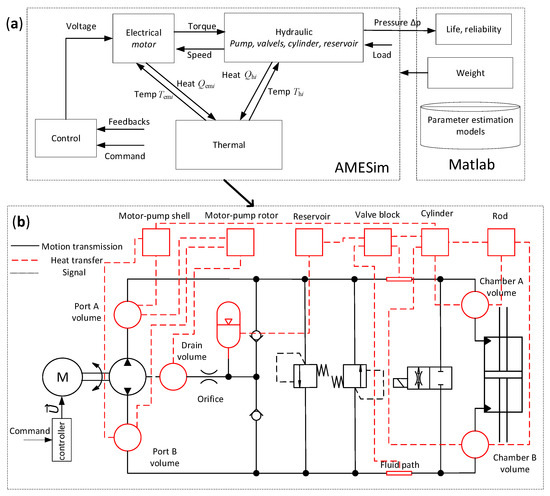
Figure 8.
The holistic EHA model for the design verification. (a) The model architecture illustrating the discipline arrangement; (b) The object-oriented dynamic model of the EHA in AMESim.
As shown in Figure 8b, the dynamic model in AMESim possesses the object-oriented modeling feature. The electric, hydraulic, thermal, and control disciplines are directly coupled using 0-Dimensional equations. The thermal model part is realized by a thermal network based on six solid nodes and eight fluid volumes (red squares and circles in Figure 8b). In line with the thermal network modeling methodology, the internal thermal resistance of the nodes or the volumes was assumed to be zero. The temperature within the node or the volume is hereby uniform. The thermal dynamics were modeled for the solid nodes while the thermal and pressure dynamics were both modeled for the fluid volumes [28,39]. The heat transfer between fluid volumes is realized by the enthalpy flow terms h of the thermal dynamic model:
where T, p, m, , and are the temperature, pressure, mass, specific heat, and the volumetric expansion coefficient of the fluid node, respectively; V and are the volumes and the enthalpy of the fluid node, respectively; and are mass flow rate and the enthalpy of the incoming flow, respectively; and is the heat exchange rate. The heat transfer between solid nodes and fluid volumes was modeled by introducing the thermal resistance parameter estimated in Section 3.2. The time-varying fluid properties (MIL-H-5606 oil properties were modeled in this paper) and the nonlinear heat generation were implemented for a more accurate simulation [28].
Because of the high-power capacity of the EHA and its corresponding high heat generation, the EHA needs a specific design for reinforcing the heat dissipation ability of its surface. In the present preliminary design stage, an expected heat exchange coefficient (unit: W/m2/K) was set for each part of the EHA surface (the surfaces of the motor-pump unit, reservoir, valve block, and cylinder), which will be used as the heat dissipation requirements of the EHA surface design in the following detailed design stage (e.g., being used as the requirements for designing fins). It is worth noting that the heat exchange coefficients are derived based on the original surface area without reinforcing the heat dissipation ability (e.g., adding fins).
Different working scenarios are defined based on the design requirements for evaluating the EHA design solution [12]. It is worth noting that the parameter sensibility and uncertainty analysis is one main task of this step. First, the parameter sensibility is examined for confirming the optimization results and tolerance definition. The insensitive parameters can be assigned with bigger tolerances for reducing manufacturing costs. Next, the design robustness to the parameter uncertainties should be examined. Previously, parameters are defined with uncertainties due to manufacturing and estimation errors. These should be confirmed as safe, otherwise, a design correction needs to be performed [28]. Finally, after all the previously illustrated design steps, the EHA preliminary design results are achieved, mainly consisting of the design parameters and the predicted EHA performance.
6. Design Results and Discussion
The HB 5802-94 durability test duty cycle together with the power and control test cycles are used for the design case of this paper [40]. After the parameter manipulation and the optimization setup, the EHA optimization design can be performed. The EHA working pressure is set at 28 MPa considering the component availability. For illustration, the obtained Pareto fronts with and without considering design robustness are presented in Figure 9. The bandwidth constraint is evaluated based on the Monto-Carlo analysis during the robust optimization. Other objectives and constraints are evaluated using deterministic calculation in both the robust and deterministic optimization because they are non-sensitive to uncertainties. This assumption will also be confirmed in the following design verification. Excluding the Monto Carlo analysis of the non-sensitive objectives and constraints can reduce the calculation cost due to the big amount of sampling of the Monto Carlo analysis. This study uses 1000 samples for the bandwidth Monto Carlo analysis. Accordingly, the robust optimization costs around 20-h CPU time while the deterministic optimization only costs 4 min on a Core i7-8665U CPU/32 G RAM computer.
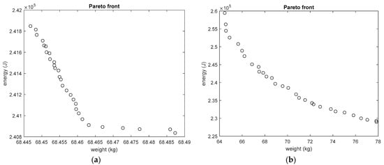
Figure 9.
The Pareto front obtained from the EHA optimization design. (a) The Pareto front by considering design robustness. (b) The Pareto front without considering the design robustness.
Figure 9 shows that the robust Pareto front spreads in a smaller space than the deterministic Pareto front, which means some deterministic optimization results are discarded due to robustness requirements. Table 3 lists the lightest and heaviest designs of the two Pareto fronts, respectively. Within the optimized parameters, the cylinder diameter is at a constant level of 113.42 ± 0.02 mm, due to its proportional relation with the required force. The motor length/diameter also always converged to the maximum 2.5 for both weight and efficiency advantages. The motor maximum torque and the pump displacement are the distinctive parameters between different design choices of the Pareto front. Bigger pumps together with bigger motors will increase the EHA weight while saving energy due to lower rotational speed and acceleration. The robust and deterministic design results achieved the same biggest pump (9.9 ± 0.01 mL/rev displacement) while the robust design results discarded a portion of the small pump side of the deterministic results, which did not meet the bandwidth constraints when considering robustness.
Table 3.
The lightest and heaviest designs of the pareto fronts.
By examining the discarded deterministic results using Monto-Carlo analysis, the smaller pumps and motors are found to be more sensitive to the moment of inertia uncertainties, which may result in the shortage of torque for driving the high-frequency sine motion under the bandwidth requirements. The analysis results of one discarded design and one preserved design are shown in Figure 10. Although all the samples of the 8.6 mL/rev displacement pump design achieve more than 8.5 Hz bandwidth, it is discarded under the 6σ design rules considering the mean shift in mass production, i.e., is less than 8 Hz [18]. These differences between the two Pareto fronts demonstrate the necessity of robustness considerations.
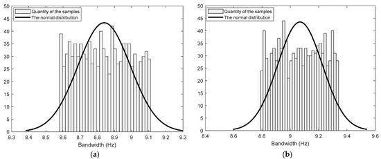
Figure 10.
The Monto Carlo analysis results of the bandwidth constraint. (a) The design using 8.6 mL/rev displacement pump. (b) The design using 9.5 mL/rev displacement pump.
Next, the robust design results are transferred to the next design stage: the design verification based on the holistic model in Figure 8. First, a sensibility analysis is performed to fully examine the optimization results. An L9(34) orthogonal array is used for designing experiments of the optimization variables (except for the cylinder diameter) within the parameter space covering the Pareto front, as shown in Table 4. The constant cylinder diameter 113.42 mm is used in the sensibility analysis due to its obvious influences on the design results. Other parameters are automatically generated for each design sample in Table 4. The uncertainties do not need to be considered for this step. The control gains are tuned for each design sample during the simulation analysis using the holistic model. Then the simulation results are converted into performance indicators complying with the design requirements, as listed in Table 4.
Table 4.
The L9(34) orthogonal array of the optimization variables and the corresponding results.
The force performance depends on the match level of the motor and the pump, i.e., bigger pumps require bigger motors. The velocity performance can always be met owing to the field weakening control of the motor, which makes better use of the motor’s high-speed abilities. The motor length/diameter ratio im shows decisive effects on the bandwidth and overshoot . This justifies the constant value 2.5 of im in the previous optimization results. Bigger pump displacement enhances the reliability because its resulting pressure and speed load can alleviate the wear of the pump. Bigger pump or motor sizes obviously increase the overall weight. But a bigger pump can save some energy due to its fewer losses caused by the frequent acceleration. The bandwidth and overshoot results also demonstrate that bigger pumps can improve the control performance robustness. In conclusion, the parameter sensibility analysis verified the previous optimization results, which achieved a good comprised point between performance and design robustness.
Next, one particular design choice can be determined from the Pareto front by the designer and customer upon the application characters [11]. Here the design using the biggest pump (9.9 mL/rev displacement) is selected due to the efficiency advantages, which can ease the thermal design. First, the nominal values of this design choice are simulated using the holistic model in Figure 8. The results reflecting the control performance are shown in Figure 11. A sweeping frequency reference is applied from 100 s to 105.5 s for examining the bandwidth , which demonstrates more than 8 Hz bandwidth. The full load 200,000 N is applied at 106 s to test the stiffness and the control error . The time-varying fluid properties and the pipe wall compliance were considered in the model to more accurately reflect these two attributes [28,39]. From 107 s to 110 s, the continuous speed under continuous load , and the overshoot are tested. Satisfying results are obtained as in Figure 11.
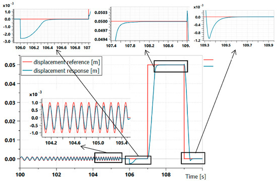
Figure 11.
The simulation results reflecting the EHA control performance.
The temperature responses under repetitive HB 5802-94 durability test duty cycles are shown in Figure 12. The EHA was simulated under the temperature critical conditions (70 °C), and its temperature came to a nearly stable state after 1-h working. All the parts are within the allowed temperature. This temperature simulation is responding to the working temperature requirements and is mainly responsible for specifying the thermal design specifications. Considering the efficiency was already optimized, the remaining over-heat risks can only be managed by the reinforced heat dissipation design of the EHA. The successful temperature management in Figure 12 was achieved by 100 W/m2/K heat transfer coefficient of the motor-pump shell and 75 W/m2/K heat transfer coefficients of the remaining surfaces. These heat transfer coefficient parameters will be transferred to the following thermal design task, in which the heat dissipation structures of the EHA surface are designed according to these values. As clarified in Section 5.1, the heat transfer coefficients are derived based on the original surface area. For example, the original motor-pump surface in the simulated design was estimated as 0.1678 m2. The 100 W/m2/K heat transfer coefficient set on it resulted in 16.78 W/K heat dissipation ability. But practically, it will be realized by extended surface area through fin structures (e.g., 0.84 m2 fin surface with 20 W/m2/K heat transfer coefficient). It is also worth noting that these reinforced heat transfer coefficients are realized by fin structures and will lead to additional weight, which should be included when evaluating the EHA total weight.
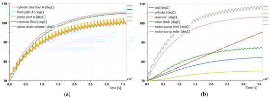
Figure 12.
The simulation results of the temperature responses. (a) The temperature responses of the fluid nodes. (b) The temperature responses of the solid nodes.
Then recalling the clarification in the optimization design, only bandwidth constraint is realized considering robustness. Therefore, the uncertainty effects are fully checked again for the selected design, which is performed by simulating the design of experiments based on the L4(23) orthogonal array with noise factors [10], as shown in Table 5, where is the total moment of inertia of the motor-pump, is the inductance of d-axis or q-axis, and other symbols can be checked in Table 6. The active parameters are designed within the manufacturing tolerances for generating the four samples. The estimation errors of the non-active parameters are treated as noise factors of each sample. Then the experimental design in Table 5 is fully simulated under the same scenario used for inspecting the nominal design parameters. The performance results are listed in Table 5 accordingly. The design results are all met under both the active parameter uncertainties and non-active parameter uncertainties. Therefore, the selected design is verified as a robust design solution.
Table 5.
The design of experiments for verifying the selected design.
Table 6.
The preliminary design results of the 30 kW EHA.
The previous optimization design and design verification deliver the preliminary EHA design results in Table 6. The design parameters are sized with specified tolerance or uncertainties, which support the following detailed design phase. The design requirements are met with robustness and the performance was optimized. It is worth noting that the non-active parameter uncertainties are specified using the average estimation errors due to the maximum estimation error being over-conservative. Moreover, due to the control sensitivity to the motor-pump inertia, the inertia uncertainties were reduced to 6% from the original 20%. These imposed risks of the motor detailed design, which may initiate the iteration loop in Figure 1 for improving the inertia estimation models.
Finally, the complete EHA preliminary design process is implemented, and the design results are obtained. The parameter estimation models, the performance calculation models, the holistic design verification model, etc., can also be reused for other high-power EHA design tasks. Moreover, the following practices are worth highlighting from the 30 kW EHA design case. As a power-on-demand actuator, the EHA design relies on the selected duty cycles, especially the energy efficiency performance and the service life. Therefore, the EHA scenario analysis and duty cycle derivation is a critical procedure for the EHA design. The design robustness is proved to be a significant factor to be considered for the EHA design. The Monte Carlo analysis and the DOE method are the two basic categories of robust design methods. The selection between them mainly depends on the calculation cost considerations. The design verification step confirms the preliminary design results by developing more accurate EHA simulation models. It again needs to perform the parameter sensibility analysis and the design robustness analysis. But it can more focus on particular design options and hereby lifts the calculation cost limitations of the simulation models. The combination of the robust optimization design and the final design verification formulates a more applicable preliminary design method for the EHA. The life and reliability calculations are based on a linear log-log S-N curve of the pump, which is still rough. It can be improved by involving the temperature and contaminant effects.
7. Conclusions
Along with the deployment extension and power increase of the EHAs, an efficient and comprehensive preliminary design method is demanded to resolve the requirement challenges and optimize the EHA performance. The general performance requirements should all be covered for governing the design process. The common uncertainty challenges of the preliminary design should also be tackled. The proposed method forms a step-by-step solution starting from design task analysis to the final design verification, which was not achieved by previous research. First, the design parameters and requirements are prepared for the following steps, which are the two subjects of the preliminary design. The parameter estimation models are developed for enabling the parameter acquirement for both the customized components and off-the-shelf components. Next, specific performance calculation models are developed for realizing the optimization design, which take the calculation efficiency and multidisciplinary coupling into consideration. Third, the optimization design is implemented by involving uncertainty handling. It is combined with a design verification step to balance the burden of the optimization and more accurate simulation. This flowchart supported by respective new measures facilitates a more applicable and efficient preliminary design method for high-power EHAs.
This paper utilized a 30 kW EHA design case for illustrating the proposed method. The general EHA requirements are all involved, which are critical as well as conflicting. A robust Pareto front specifying the weight and efficiency objectives is obtained. It not only demonstrated the optimized results but also showed deep insight into the EHA performance. The bandwidth and reliability are found to be the bottlenecks for improving the EHA performance. The pump displacement is found to be a regulating parameter for balancing the robustness and the weight. The following design verification based on a holistic model further enhanced the applicability and confidence of the design. All the design requirements are examined at a higher fidelity level. The design robustness is also confirmed again. Finally, the full design results are produced for the design task, arriving at 69.92 kg mass and 0.999 reliability.
The proposed method is an open flowchart for continuous improvement. The primary perspectives are the reliability and optimum of the design results. Because of the early design stage, uncertainties always exist but are usually resolved by sacrificing the optimum. More accurate parameter estimation [33] can reduce the cost of the uncertainties. This can be progressed by using advanced estimation models and improving the accuracy based on the feedback from the following manufacturing results. The performance calculation models can be improved for exploiting the performance potential. For example, the present control performance calculation is based on the PID control method. Higher performance can be designed if more advanced control is utilized for the performance calculation. The design can also involve more component-level parameters for optimizing the component and EHA at the same time. This can be pushed ahead by using more advanced multidisciplinary optimization methods for handling a bigger number of parameters and disciplines.
Author Contributions
Conceptualization, Y.F. and X.H.; methodology, X.H.; parameter analysis and estimation method, T.G.; calculation models of the objectives and constraints, T.G.; robust optimization design method, T.G.; modeling and simulation for design verification, X.H. and T.M.; results analysis, X.H. and T.M.; writing—original draft preparation, T.G.; writing—review and editing, T.M. and Y.F.; supervision, T.M. and Y.F.; project administration, Y.F.; funding acquisition, Y.F. All authors have read and agreed to the published version of the manuscript.
Funding
This research was funded by Chinese Civil Aircraft Project, grant number MJ-2017-S49.
Institutional Review Board Statement
Not applicable.
Informed Consent Statement
Not applicable.
Conflicts of Interest
The authors declare no conflict of interest.
References
- Alden, R.E. Flight demonstration, evaluation and proposed applications for various all electric flight control actuation system concepts. In Proceedings of the Aerospace Design Conference, Irvine, CA, USA, 16–19 February 1993. [Google Scholar]
- Quan, Z.; Ge, L.; Wei, Z.; Li, Y.; Quan, L. A survey of powertrain technologies for energy-efficient heavy-duty machinery. Proc. IEEE 2021, 109, 279–308. [Google Scholar] [CrossRef]
- Kaminaga, H.; Ko, T.; Masumura, R.; Komagata, M.; Sato, S.; Yorita, S.; Nakamura, Y. Mechanism and control of whole-body electro-hydrostatic actuator driven humanoid robot hydra. In Proceedings of the International Symposium on Experimental Robotics, Nagasaki, Japan, 3–8 October 2016. [Google Scholar]
- da Silva, J.P.D.; Neto, A.P.; De Negri, V.J.; Orth, A. Experimental evaluation of an electro-hydrostatic actuator for subsea applications in a hyperbaric chamber. In Proceedings of the 12th International Fluid Power Conference, Dresden, Germany, 12–14 October 2020. [Google Scholar]
- Garrison, M.; Steffan, S. Two-fault tolerant electric actuation systems for space applications. In Proceedings of the 42nd AIAA/ASME/SAE/ASEE Joint Propulsion Conference & Exhibit, Sacramento, CA, USA, 9–12 July 2006. [Google Scholar]
- Hermansson, R.; Närvänen, V.; Kajaste, J.; Calonius, O.; Pietola, M.; Kuosmanen, P. Experimental study on energy efficiency of two-cylinder direct driven hydraulic system in a large-scale test bench. In Proceedings of the ASME/BATH 2021 Symposium on Fluid Power and Motion Control, Virtual, Online, 19–21 October 2021. [Google Scholar]
- Gausemeier, J.; Moehringer, S. VDI 2206-a new guideline for the design of mechatronic systems. IFAC Proc. Vol. 2002, 35, 785–790. [Google Scholar] [CrossRef]
- Andersson, J.; Krus, P.; Nilsson, K. Optimization as a support for selection and design of aircraft actuation systems. In Proceedings of the 7th AIAA/USAF/NASA/ISSMO Symposium on Multidisciplinary Analysis and Optimization, St. Louis, MO, USA, 2–4 September 1998. [Google Scholar]
- Andersson, J.; Krus, P.; Nilsson, K.; Storck, K. Modelling and simulation of heat generation in electro-hydrostatic actuation systems. In Proceedings of the JFPS International Symposium on Fluid Power, Tokyo, Japan, 1 November 1999; pp. 537–542. [Google Scholar]
- Andersson, J. Multiobjective Optimization in Engineering Design: Applications to Fluid Power Systems. Ph.D. Thesis, Linköpings Universitet, Linköping, Sweden, 2001. [Google Scholar]
- Xue, L.; Wu, S.; Xu, Y.; Ma, D. A simulation-based multi-objective optimization design method for pump-driven electro-hydrostatic actuators. Processes 2019, 7, 274. [Google Scholar] [CrossRef]
- Budinger, M.; Reysset, A.; Halabi, T.E.; Vasiliu, C.; Maré, J.C. Optimal preliminary design of electromechanical actuators. Proc. Inst. Mech. Eng. Part G J. Aerosp. Eng. 2014, 228, 1598–1616. [Google Scholar] [CrossRef]
- Liscouët, J.; Budinger, M.; Maré, J.C.; Orieux, S. Modelling approach for the simulation-based preliminary design of power transmissions. Mech. Mach. Theory 2011, 46, 276–289. [Google Scholar] [CrossRef]
- Arriola, D.; Schäffr, A.; Thielecke, F. A model-based method to assist the architecture selection and preliminary design of flight control electromechanical actuators. In Proceedings of the Recent Advances in Aerospace Actuation Systems and Components, Toulouse, France, 16–18 March 2016; pp. 166–174. [Google Scholar]
- Chakraborty, I.; Mavris, D.N.; Emeneth, M.; Schneegans, A. A methodology for vehicle and mission level comparison of More Electric Aircraft subsystem solutions: Application to the flight control actuation system. Proc. Inst. Mech. Eng. Part G J. Aerosp. Eng. 2015, 229, 1088–1102. [Google Scholar] [CrossRef]
- Roos, F. Towards a Methodology for Integrated Design of Mechatronic Servo Systems. Ph.D. Thesis, KTH, Stokholm, Sweden, 2007. [Google Scholar]
- Pettersson, M.; Ölvander, J. Drive train optimization for industrial robots. IEEE Trans. Robot. 2009, 25, 1419–1424. [Google Scholar] [CrossRef]
- Lei, G.; Wang, T.; Zhu, J.; Guo, Y.; Wang, S. System-level design optimization method for electrical drive systems-robust approach. IEEE Trans. Ind. Electron. 2015, 62, 4702–4713. [Google Scholar] [CrossRef]
- Shi, Z.; Sun, X.; Cai, Y.; Yang, Z. Robust design optimization of a five-phase PM hub motor for fault-tolerant operation based on Taguchi method. IEEE Trans. Energy Convers. 2020, 35, 2036–2044. [Google Scholar] [CrossRef]
- Sun, X.; Wan, B.; Lei, G.; Tian, X.; Guo, Y.; Zhu, J. Multiobjective and multiphysics design optimization of a switched reluctance motor for electric vehicle applications. IEEE Trans. Energy Convers. 2021, 36, 3294–3304. [Google Scholar] [CrossRef]
- Gerada, D.; Golovanov, D.; Xu, Z.; Papini, L.; Degano, M.; Zhang, H.; Gerada, C. Holistic electrical machine optimization for system integration. In Proceedings of the 2017 IEEE 3rd International Future Energy Electronics Conference and ECCE Asia, Kaohsiung, Taiwan, 3–7 June 2017; pp. 980–985. [Google Scholar]
- Golovanov, D.; Papini, L.; Gerada, D.; Xu, Z.; Gerada, C. Multidomain optimization of high-power-density PM electrical machines for system architecture selection. IEEE Trans. Ind. Electron. 2017, 65, 5302–5312. [Google Scholar] [CrossRef]
- Kim, K.C.; Lee, J.; Kim, H.J.; Koo, D.H. Multiobjective optimal design for interior permanent magnet synchronous motor. IEEE Trans. Magn. 2009, 45, 1780–1783. [Google Scholar]
- De Giorgi, F.; Budinger, M.; Hazyuk, I.; Reysset, A.; Sanchez, F. Reusable Surrogate Models for the Preliminary Design of Aircraft Application Systems. AIAA J. 2021, 59, 2452–2490. [Google Scholar] [CrossRef]
- Hong, G.; Wei, T.; Ding, X.; Duan, C. Multi-objective optimal design of electro-hydrostatic actuator driving motors for low temperature rise and high power weight ratio. Energies 2018, 11, 1173. [Google Scholar] [CrossRef]
- Kreitz, T.; Arriola, D.; Thielecke, F. Virtual performance evaluation for electro-mechanical actuators considering parameter uncertainties. In Proceedings of the Recent Advances in Aerospace Actuation Systems and Components, Toulouse, France, 2–3 April 2014; pp. 136–143. [Google Scholar]
- Zhang, C.; Han, X.; Minav, T.; Fu, Y. Multi-objective optimization design of a 30 kW Electro-hydrostatic Actuator. Proceedings 2020, 64, 5. [Google Scholar]
- Han, X.; Zhang, P.; Minav, T.; Fu, Y.; Fu, J. A Modeling and Simulation Method for Preliminary Design of an Electro-Variable Displacement Pump. J. Vis. Exp. 2022, 184. [Google Scholar] [CrossRef]
- Budinger, M.; Liscouët, J.; Hospital, F.; Mare, J.C. Estimation models for the preliminary design of electromechanical actuators. Proc. Inst. Mech. Eng. Part G J. Aerosp. Eng. 2012, 226, 243–259. [Google Scholar] [CrossRef]
- Frameless Spindle Motors-HKW Series. Available online: https://ph.parker.com/us/en/frameless-spindle-motors-hkw-series (accessed on 9 October 2022).
- Negoita, G.C.; Mare, J.C.; Budinger, M.; Vasiliu, N. Scaling-Laws Based Hydraulic Pumps Parameter Estimation. UPB Sci. Bull. Series D 2012, 74, 199–208. [Google Scholar]
- Kauranne, H.O.J.; Kajaste, J.T.; Ellman, A.U.; Pietola, M.T. Applicability of pump models for varying operational conditions. In Proceedings of the ASME International Mechanical Engineering Congress and Exposition, Washington, DC, USA, 15–21 October 2003; pp. 45–54. [Google Scholar]
- Tahkola, M.; Keränen, J.; Sedov, D.; Far, M.F.; Kortelainen, J. Surrogate modeling of electrical machine torque using artificial neural networks. IEEE Access 2020, 8, 220027–220045. [Google Scholar] [CrossRef]
- Martins, J.R.R.A.; Lambe, A.B. Multidisciplinary design optimization: A survey of architectures. AIAA J. 2013, 51, 2049–2075. [Google Scholar] [CrossRef]
- Ritari, A.; Vepsäläinen, J.; Kivekäs, K.; Tammi, K.; Laitinen, H. Energy Consumption and Lifecycle Cost Analysis of Electric City Buses with Multispeed Gearboxes. Energies 2020, 13, 2117. [Google Scholar] [CrossRef]
- Yu, B.; Wu, S.; Jiao, Z.; Shang, Y. Multi-objective optimization design of an electrohydrostatic actuator based on a particle swarm optimization algorithm and an analytic hierarchy process. Energies 2018, 11, 2426. [Google Scholar] [CrossRef]
- Pawlus, W.; Hansen, M.R.; Choux, M.; Hovland, G. Mitigation of fatigue damage and vibration severity of electric drivetrains by systematic selection of motion profiles. IEEE/ASME Trans. Mechatron. 2016, 21, 2870–2880. [Google Scholar] [CrossRef]
- Weiss, J. Control actuation reliability and redundancy for long duration underwater vehicle missions with high value payloads. In Proceedings of the 2014 Underwater Intervention Conference, New Orleans, LA, USA, 11–13 February 2014. [Google Scholar]
- Søren, K.; Sebastian, M.; Torben, A.O.; Morten, K.E.; Jürgen, W.; Lasse, S. Thermo-Hydraulic Modelling and Experimental Validation of an Electro-Hydraulic Compact Drive. Energies 2021, 14, 2375. [Google Scholar]
- Han, X.; Minav, T.; Fu, J.; Fu, Y.; Pietola, M.; Zhang, P. Multi-disciplinary model for preliminary design of electro-mechanical servo pump. In Proceedings of the 16th Scandinavian International Conference on Fluid Power, Tampere, Finland, 22–24 May 2019; pp. 362–374. [Google Scholar]


Publisher’s Note: MDPI stays neutral with regard to jurisdictional claims in published maps and institutional affiliations. |
© 2022 by the authors. Licensee MDPI, Basel, Switzerland. This article is an open access article distributed under the terms and conditions of the Creative Commons Attribution (CC BY) license (https://creativecommons.org/licenses/by/4.0/).