Review

The Prediction and Correction Method of Aircraft Static Aeroelastic Effects: A Review of Recent Progress

China Aerodynamics Research and Development Center, Institute of High Speed Aerodynamics, Mianyang 621000, China
*
Author to whom correspondence should be addressed.
Actuators 2022, 11(11), 309; https://doi.org/10.3390/act11110309
Submission received: 19 August 2022 / Revised: 9 October 2022 / Accepted: 12 October 2022 / Published: 27 October 2022
(This article belongs to the Section Aerospace Actuators)

Abstract

:
This paper comprehensively reviews the progress of static aeroelastic effect prediction and correction methods for aircraft, including the damage and protection of aeroelastic. It is significantly important to determine the similarity conditions and static aeroelastic scaling modeling in wind tunnel experiments to obtain accurate aerodynamic characteristics. Meanwhile, similar stiffness distribution, manufacturing materials, and processing technology are strongly associated with the simulation of aircraft structural dynamics. The structural layout of the static aeroelastic model, including plate type, beam type, bearing skin type, and full structural similarity type, are described in detail. Furthermore, the wind tunnel and test technique also play an important role in static aeroelastic experiments. It is worth noting that computational fluid dynamics (CFD) and computational structure dynamics (CSD) have attracted increasing attention from researchers for application in aeroelastic analysis of the flow field. The research status and key technologies of aeroelastic numerical simulation of aircraft are introduced in detail. Additionally, this paper briefly introduces the static aeroelastic prediction and correction method, especially the widely practiced K-value method.

1. Introduction

With the rapidly growing demand for aircraft in military and civil domains, the requirements for aircraft performance are constantly improving [1,2,3,4]. At present, the development trend of aircraft includes high cruise speed, low fuel consumption, and high-performance flight quality [5,6,7]. Therein, the prediction and correction of static aeroelasticity are very important for the safe flight of aircraft. The static aeroelasticity investigation is interdisciplinary, combining aerodynamic, elastic, and inertial forces [8,9]. Static aeroelastic deformation has a significant impact on the load distribution, control efficiency, static and dynamic stability of aircraft [10]. In general, there are two typical static aeroelastic problems in conventional aircraft. Firstly, the pressure distribution of the wing and its adjacent components are changed by the wing elastic deformation, and even trigger the flow separation of the lift surface [11]. This leads to variation in the lift characteristics, drag characteristics, torque characteristics, and static/dynamic stability of the whole aircraft. Secondly, the structural deformation of the wing has a great impact on the efficiency of the control surface [12]. For example, the efficiency of the rudder surface maybe decreased, slightly deformed and even cause the rudder surface to stop working [13]. Therefore, it is increasingly important to focus on static aeroelastic effects in aircraft design.
As early as the development of aircraft, aerodynamicists and aircraft designers have been engaged in experimental research related to static aeroelasticity [14,15,16]. In 1899, the Wright brothers improved the designed wing by controlling the bending/torsion of the wing tip to achieve the purpose of enhancing roll control. This was the first experiment to use the static aeroelastic effect of the wing. With the increasing complexity and costs of aircraft, the danger of flight tests and the progress of wind tunnel test technology, researchers gradually began to use the similarity principle to reproduce the aeroelastic phenomenon of aircraft in the wind tunnel [17,18]. To sum up, it is seriously important to establish a complete set of aircraft static aeroelastic model designs, wind tunnel tests and numerical simulation technologies to explore the correction measures of wind tunnel and flight data. The research results can not only provide necessary basic data for aircraft design, but also provide technical support for aerodynamic/structural optimization.

2. Literature Review

2.1. Challenges and Progress in Aeroelasticity

Compared with the traditional wing, a high-aspect-ratio wing produces more elastic structural deformation under the excitation of aerodynamic and inertial forces. However, the linear relationship between displacement and strain is no longer established due to large elastic deformation, i.e., geometric nonlinearity [19,20]. In general, the lift line has the highest slope and most significant change at transonic speed. Meanwhile, the fluid-structure interaction is also the most sensitive, and even a slight change in the structure may have a great impact on the aerodynamic characteristics of the aircraft [21]. Due to the high efficiency of transonic flight, the cruising speed range of many large aircrafts lies in this range. However, neither the theoretical analysis nor the numerical computation can accurately reflect the flowing nature in the transonic range [22]. With the advancement of aviation technology, the performance of large aircraft has also improved significantly. It brings great difficulties to experimental model development, wind tunnel equipment, and test technology, which leads to great costs in terms of both expenditure and test cycle. For example, with repeated testing and modification of design parameters in the aircraft design and development process, the resulting prolonged development cycle and increased costs are unacceptable [23].
In the last decade, wind tunnel experiments, computational modeling, instrumentation, and flight testing have made significant progress in aerostatic analysis. For example, in terms of wind tunnel experiments, Tang and Dowell [24] experimented with several models and concluded some new perspectives to investigate the nonlinear aeroelastic phenomena, flutter, and limit cycle oscillation. They used a “mirror” deflection technique to measure the tip static aeroelastic deflections of the wings. As for computational modeling, computational fluid dynamics has been widely used in the field of aerodynamics with the improvement of computer performance and algorithms [25,26]. Drikakis et al. concluded the current advanced technologies and existing challenges in reference [27], including Reynolds averaged Navier–Stokes (RANS) modeling, turbulence modeling, and multi-physics field modeling. Considering aerodynamic nonlinearity, large structural deformation, and the investigation of anisotropic material properties, more accurate test data can be obtained by using deformation-measuring instrumentations, such as stress/strain sensors, pressure sensors, etc. [28]. Therefore, high-precision wind tunnel test data can be used to correct the results of theoretical analysis and numerical calculations. For flight testing, Sundresan et al. [29] reviewed four testing techniques recently improved, including aeroelasticity testing techniques, flutter analysis, flutter suppression techniques, and non-linear aeroelasticity. Especially in aeroelasticity testing techniques, the measurement of natural frequencies and mode shapes, steady state testing, and dynamic aeroelastic testing were introduced in detail.

2.2. Static Aeroelastic Wind Tunnel Test

It has been proved that the effect of aerodynamic load on aircraft structure in flight is difficult to be simulated only by the scaling model with similar rigid characteristics [30]. The error can potentially further affect the initial design results with the increase in aircraft flight speed, which cannot accurately reflect the structural response characteristics of the prototype aircraft. Consequently, the key technologies of the static aeroelastic wind tunnel test are mainly in the determination of similarity conditions, model design and test technology.

2.2.1. Determination of Similarity Conditions

The static aeroelastic wind tunnel test model is much smaller than the prototype aircraft, and the wind tunnel flow field environment is quite different from the real flight atmospheric conditions. To ensure that the wind tunnel test results obtained are consistent with the real flight, it is necessary to follow similar theories such as geometric similarity [31], stiffness similarity [32], and structural similarity [33,34]. For example, Molyneux [35] investigated the similarity conditions between aircraft and aeroelastic wind tunnel models as early as 1964 and pointed out that dimensionless parameters representing aerodynamics, structure, and their coupling can be used for matching. The dimensionless differential equation for the scale-up analysis and the simplified method suitable for various flow conditions were proposed in detail. Among them, the static aeroelastic wind tunnel test was mainly used to determine the influence of the static aeroelastic effect on aerodynamic performance, stability, and rudder effect. Therefore, the static aeroelastic model should meet the conditions of similar stiffness distribution [36]. Roskam et al. [37] investigated the wind tunnel test data without meeting the condition of mass distribution similarity. According to the static aeroelastic wind tunnel test data of the Boeing SST model, the specific correction method of longitudinal aerodynamic derivative was given in detail. The classical aeroelastic similarity theory was mainly aimed at the flutter wind tunnel test, which was more suitable for static aeroelastic wind tunnel test research and convenient for static aeroelastic wind tunnel model design. In recent years, Jennifer et al. [38] have systematically studied the similarity parameters that needed to be attained, the static aeroelastic design requirements, and the uncertainty factors that affect the flow field parameters of the wind tunnel. The conclusions were as follows, firstly, the static stability parameters and control derivatives obtained from the static aeroelastic wind tunnel experiments were more reliable than those based on the theoretical analysis. Secondly, the deformation characteristics under static load were similar to those of aircraft in the static aeroelastic similarity model. Thirdly, in the process of testing static aeroelastic wind tunnel models, it was allowed to ignore the similarity requirements of mass ratio, Reynolds number and Froude number under specific circumstances. Finally, the ratio of stiffness to aerodynamic force was a similarity ratio parameter that must be satisfied between the static aeroelastic model and real aircraft.
According to the current status, it can be seen that scholars have systematically investigated the design criteria of static aeroelastic wind tunnel models, the physical parameters, and the influence of similarity parameters on experiment data.

2.2.2. Static Aeroelastic Scaling Modeling Technology

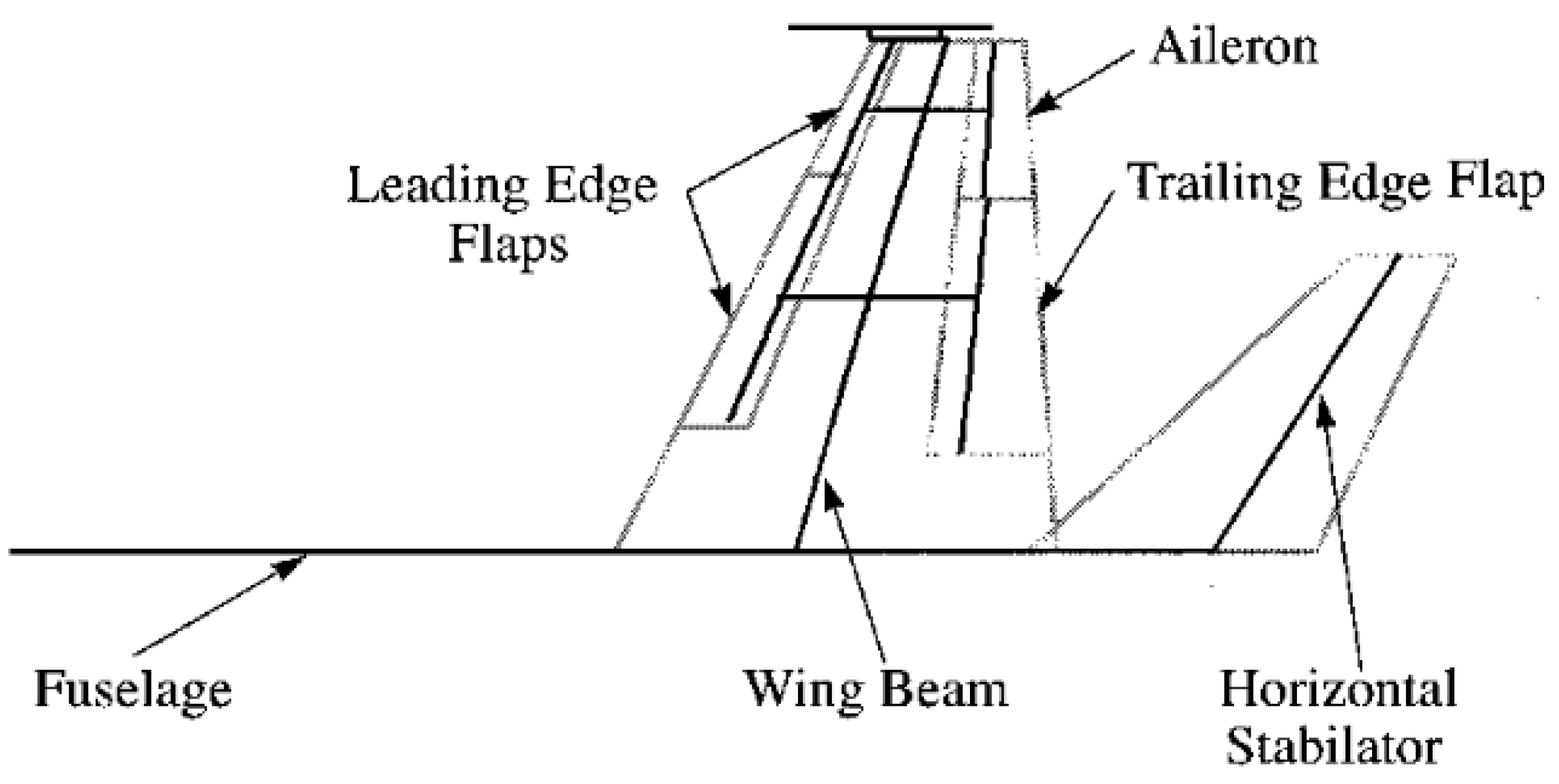
A static aeroelastic model not only needs to simulate the aerodynamic shape of aircraft with high fidelity but also accurately simulate the structural dynamic characteristics of aircraft. Therefore, the static aeroelastic model must strictly maintain conditions similar to the aerodynamic force and stiffness of the aircraft. However, the size of the scaling model is much smaller than that of the real aircraft, which requires advanced manufacturing materials and processing technology to design the static aeroelastic wind tunnel experiment model. As shown in Figure 1, the early static aeroelastic experiment model usually used metal materials to process the skeleton to meet the requirements of stiffness and strength [33]. The gap was filled with plastic, cork or silicone rubber, and the surface was covered with a fiber cloth. However, there are two disadvantages of this design method. Firstly, it leads to the distortion of stiffness simulation. For example, Dorothy et al. [39] used metal aluminum and flexible steel sheets for the model fuselage and elastic wing, respectively, and the shape was made of a glass cloth shape. Because the structural similarity theory was not strictly followed, the real static aeroelastic effect of the wing could not be obtained accurately. Secondly, it was difficult to design a model that met the requirements of stiffness reduction and strength simultaneously for advanced high-aspect-ratio aircraft according to the existing properties of metal materials. It can be seen in Table 1 that composite materials are widely used in aerospace, electronics and electrical fields because of their unique properties, such as low density, fatigue resistance and corrosion resistance.
Another major characteristic of composite material is the designability of laminates, which enables the structural components of aircraft to produce the desired elastic deformation under load conditions and greatly improves the structural efficiency. However, there are also many damage forms of composite material, including the damage of fibers and matrix, and the warpage in the case of asymmetry and disequilibrium. Therefore, it is necessary to consider the failure criteria and the requirements of processing technology in the optimization design and ply design. The design variables can be used in the optimization design of composite materials according to the different laying forms. Meanwhile, the sensitivity-based optimization algorithm [40], the genetic algorithm [41], and the genetic/sensitivity hybrid algorithm [42] can be applied to optimization. Among them, the sensitivity algorithm belongs to a local algorithm. Although it has a fast convergence speed, the optimization result depends heavily on the initial value of the design variables. The genetic algorithm is a global algorithm. It has a wide search range but takes a long time to calculate and requires high computing resources. The genetic/sensitivity hybrid optimization algorithm combines the advantages of the previous two algorithms, which has good application results in the optimization design of composite materials.
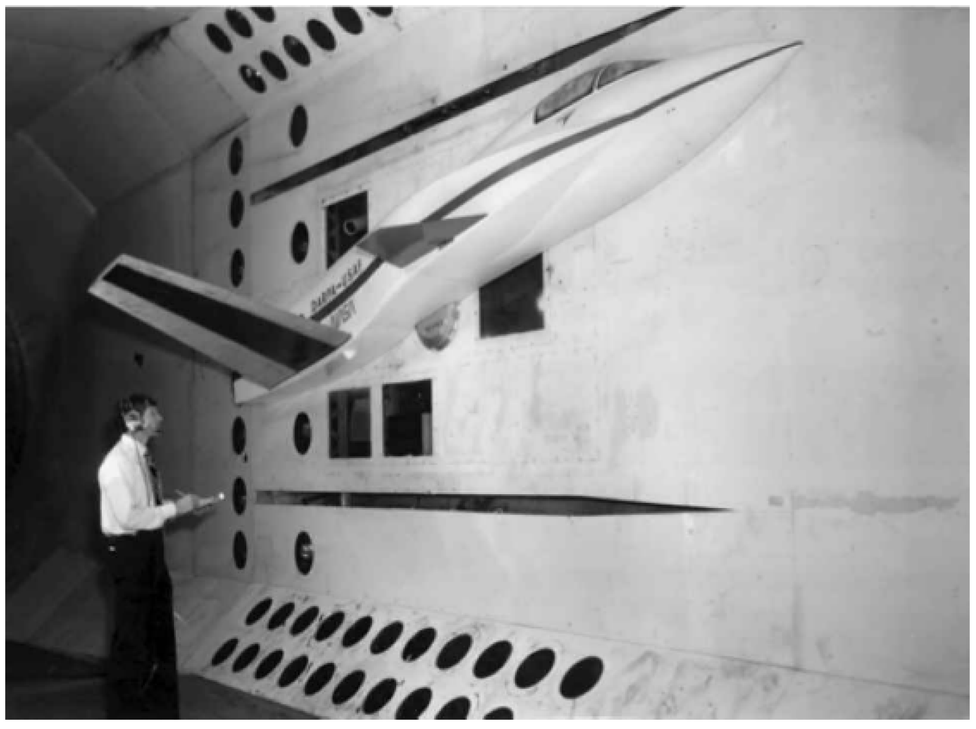
With the wide application of composite materials, some aerodynamic researchers have introduced the forward swept wing layout into aircraft design for static aeroelastic wind tunnel experiments. The above design mainly aimed at the effects of the ply direction of composite materials and the wing sweep angle on the wing divergence characteristics. For example, static aeroelastic wind tunnel tests were used to verify the new aerodynamic layout in the transonic dynamics wind tunnel of NASA Langley Research Center [43]. The model was installed on the side wall of the wind tunnel in the form of half mold, as shown in Figure 2. Experiments showed that the concept of forward swept wing layout and the theoretical analysis tool were, respectively, reasonable and correct. Blair et al. [44] designed a small aspect ratio elastic wing model of a full composite structure. They obtained the relationship between the material fiber ply direction and the divergence dynamic pressure of the wing. On this basis, William et al. [45] used similar material design to investigate the influence of material fiber ply direction on rudder surface reaction and verified some theoretical analysis methods.
Due to the large stiffness of the fuselage and external stores, in general, the deformation of the above components can be ignored in the design process of the static aeroelastic model. Therefore, these components only simulate the shape, not the dynamic characteristics, of the structure to ensure that the stiffness and strength are large enough. According to the current research status, the aeroelastic model design mainly adopts the following four types of structural layout.
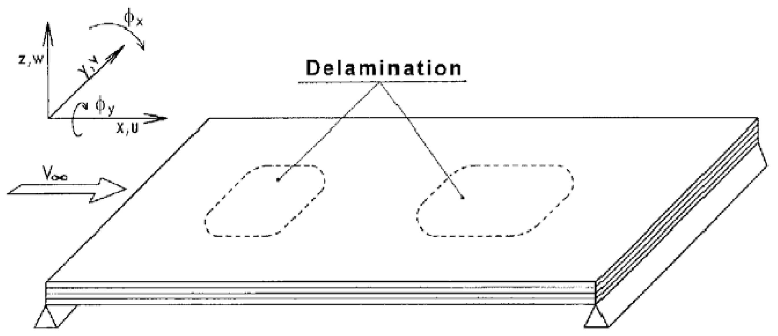
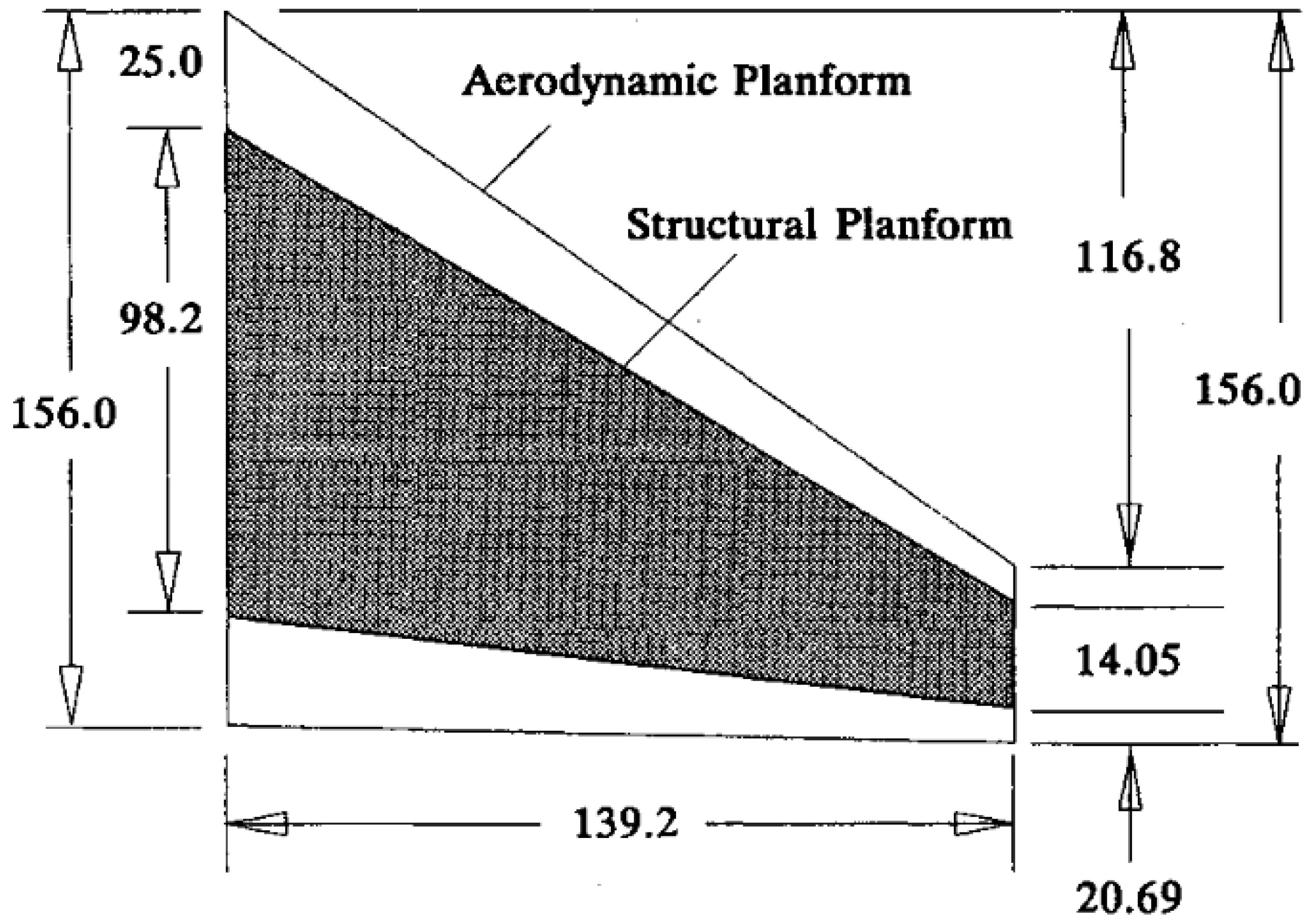
Firstly, the plate type structure layout, for different research purposes or physical prototypes, is, respectively, divided into the multi-layer plate, the equal thickness plate, and the dimensional plate layout. The multi-layer plate structure mainly uses the thickness change of the plate to simulate the stiffness and mass characteristics. For example, Ostachowicz and Kaczmarczyk [46] proposed a multi-layer composite plate with delamination subjected to aerodynamics load, as shown in Figure 3, where the effect of delamination on the natural frequencies was analyzed in detail. The equal thickness plate structure mainly simulates the stiffness and mass distribution characteristics by opening holes, such as the design in Figure 4 [47]. The dimensional plate layout is generally designed and manufactured with composite materials, which has been commonly seen in the last two decades. The plate structure layout is mainly used in situations where the stiffness and mass characteristics change gently. Its main characteristics are simple structure modeling, easy processing, fewer design variables, and easy optimization.
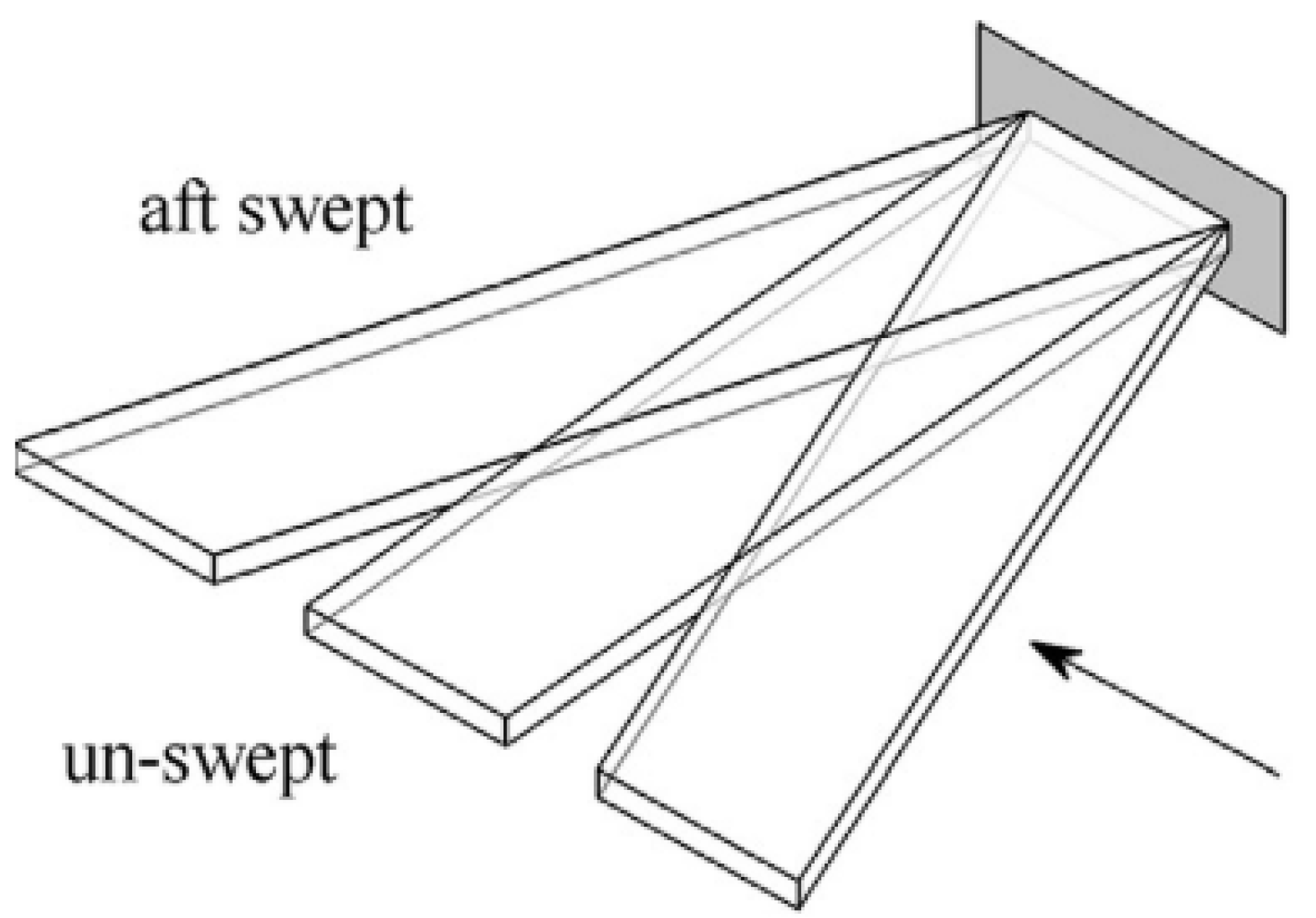
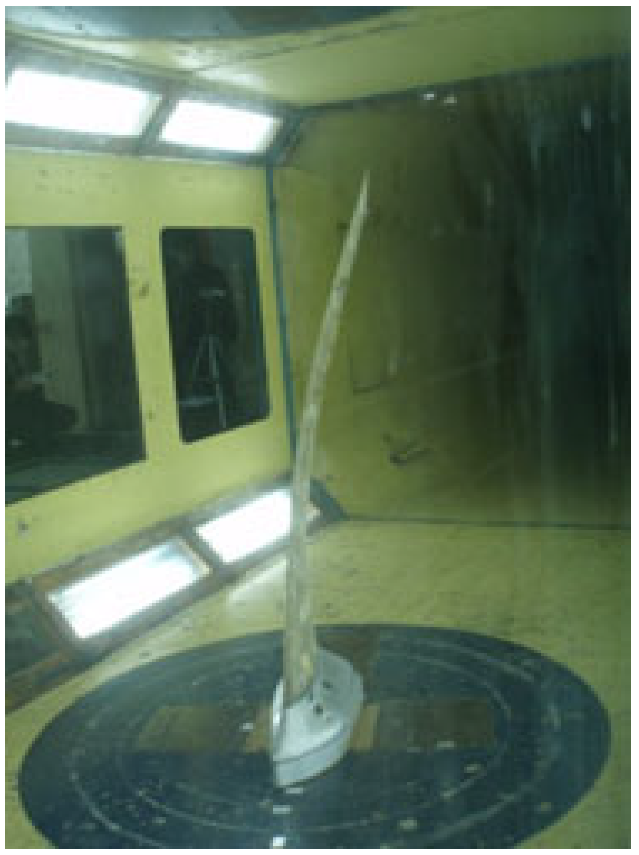
Secondly, beam type structure layout. The layout can be divided into single beam type, double beam type, and mesh type according to different design requirements. In detail, the single beam structure can be realized by changing the section shape of the main beam, adding flanges and adding ribs. The beam type structure layout is formed by covering or filling light foam and high-strength fiber cloth on the outside and bearing pressure load. It is not only suitable for wings with large or small aspect ratios but also for the design and manufacture of elastic components such as fuselage. However, the structure and designable variables of the beam-type structure layout are relatively complex; structural modeling and optimization design are more difficult than that of plate structure layout. To meet the requirements of accurate simulation of the strength and shape of the model, processing technology is highly required. For example, Martin [48] used a single beam structure to conduct low-speed static aeroelastic wind tunnel tests on a high-aspect-ratio swept wing, as shown in Figure 5. The results showed that with the increase in wind speed, the lift line slope and aileron efficiency of the wing were significantly reduced, and the wing had obvious deformation along the spanwise direction. The double beam type can be realized by changing the shape parameters of the main beam section and the torsional connecting truss in the middle. Kreshock et al. [49] proposed a double beam wing to restrain the freedom degrees of pitch and yaw. The mesh type can be realized by adjusting the layout of the beam frame and optimizing the geometric parameters of the section.
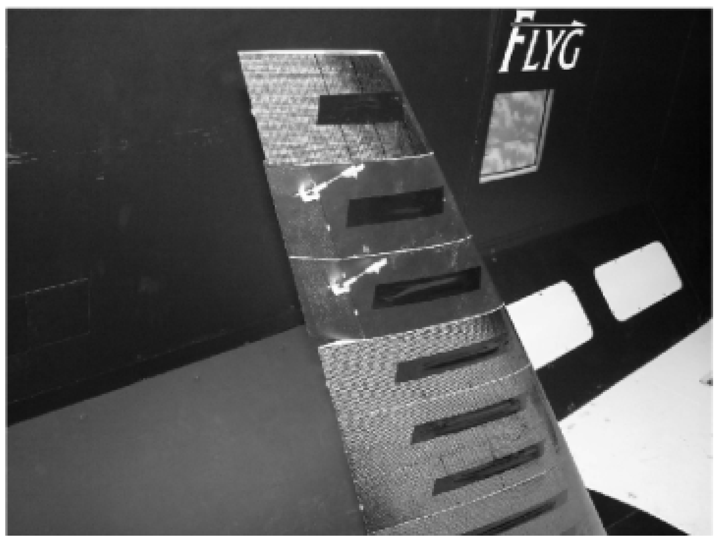
Thirdly, bearing a skin-type structural layout, the clearance can be eliminated by filling the interior with lightweight materials to meet the requirements of the stiffness and strength design. Usually, the skins of the experiment model are designed and made of composite materials. The specific manufacturing method is generally to lay high-strength carbon fiber or other special materials in the pre-processed mold according to the design requirements. The bearing skin type structure layout has developed with the emergency of cutting design and processing technology of composite materials [28], as shown in Figure 6. It is characterized by high requirements for material properties and great difficulty in optimization. It is depicted in Figure 7 that Alenander et al. [50] proposed a hybrid metal-composite rod elements structure to protect the system from impacts and the environment. The numerical results showed that about 5% of the weight can be saved. However, the process requirements are not convenient for test equipment embedding, and it is difficult to remedy errors in the processing process, with high production costs.
Fourthly, full structural similarity type structure layout. The structure layout is completely based on the structural form of the physical prototype and is scaled down according to the similarity theorem. Therefore, the geometric scale ratio must be significantly large, resulting in only being suitable for large-scale wind tunnels. However, it was rarely used in the actual aeroelastic test due to the complex process design and manufacturing process. According to the previous description, the structural dynamic characteristics of the aeroelastic model are needed to further optimize the structural layout of the preliminary design in addition to the full structural similarity type structure layout. The previous aeroelastic model design methods are mainly based on manual conversion, which mainly depends on engineering experience to design the original structure. To obtain structural shape similarity, researchers need to repeatedly adjust the design parameters. It is time-consuming and labor-intensive to obtain satisfactory results. With the rapid development of computer-aided optimization (CAO), the application of relevant optimization methods in aircraft designs or static aeroelastic model designs can greatly improve the speed and accuracy of structural refinement designs. For example, Mark et al. [51,52,53] investigated a structural design optimization method for aeroelastic models of small aspect ratio airfoils, as shown in Figure 8. The method separated the optimization design of structural stiffness and structural quality. The optimization variable was the thickness of the wing “cross” skeleton along the spanwise/chord direction. Vasily et al. [54,55] designed an aeroelastic model optimization method considering both structural stiffness and structural mass characteristics. The above two methods must be given the target value before optimization, which belongs to the traditional deterministic optimization algorithm. However, some uncertain factors such as model production cost are not considered in the above method, which leads to conservative results and increases in model production cost. Brian et al. [56] investigated the structural method of the aeroelastic model of a multi-objective platform combined with NASTRAN, based on reliability optimization technology.

2.2.3. High-Speed Static Aeroelastic Wind Tunnel and Test Technology

To attain the similarity conditions and reduce the design difficulty of the test model, the static aeroelastic test simulation has special requirements for the wind tunnel. Firstly, a larger size wind tunnel test section is required to simulate the geometric shape and structural dynamic characteristics of aircraft with high fidelity. Secondly, the wind tunnel is required to have the ability of variable pressure to simulate the change in flight altitude. Finally, the wind tunnel should be equipped with a lower boundary of the velocity pressure, and the test velocity pressure and Mach number should be rapidly reduced in case of dangerous situations. At present, the most suitable wind tunnel for aeroelastic tests in the world is the 16-feet transonic dynamic wind tunnel at NASA Langley Research Center [57]. It has a wide range of variable pressure test capabilities. The wind tunnel is also equipped with a bypass pressure relief valve to quickly reduce the test Mach number and velocity pressure in case of reducing the load borne by the model. Since the wind tunnel was upgraded in 1959 to better carry out aeroelastic test research, a large number of aeroelastic tests have been successfully completed.
The technology required for a static aeroelastic wind tunnel test usually includes the following aspects. Firstly, ground flexibility matrix measurement and modal test technology. The early flexibility matrix measurement was manual measurement by weight loading [52]. At present, this work can be completed quickly and efficiently by using the automatic flexibility matrix loading system. The above system can carry out ground modal tests such as the hammering method, random excitation method, and sinusoidal sweep frequency excitation method according to different test model sizes and test requirements. Secondly, static force and moment measurement test technology. The measurement technology is based on the force measuring balance to predict the effect of static aeroelasticity on the aerodynamic performance, stability, and rudder efficiency of the model. Thirdly, pressure load measurement test technology. By measuring the influence of static aeroelasticity on the pressure load distribution, the location and separation characteristics of the wing shock wave are determined, and the test data are also provided for verifying the numerical calculation method. The measurement technology can be realized by the pressure sensor, digital scanning valve or pressure sensitive coating technology. Fourthly, model deformation measurement technology. Typical non-contact measurement techniques include the video model deformation method, projection Moiré interferometry method, and optotrakTM method [58]. Fifthly, surface flow pattern model and spatial flow field characteristics measurement technology. The main purpose is to evaluate the influence of static aeroelasticity on the flow characteristics of the model, which is generally applied in the field of flow mechanism analysis and numerical calculation method verification.
As shown in Figure 9, Perry et al. [59,60,61] investigated the aeroelastic test using the half mold sidewall support method, in which several strain gauges were arranged at the 2/3 half span of the wing to measure the wing bending and torsional strains. The deformation and aerodynamic characteristics of the wing model during the combined deflection of the rudder surface are obtained. In addition, the effects of linearization theory and pressure distribution on the static stability of aircraft were verified and analyzed, respectively. Burner et al. [62] introduced particle image velocimetry technology into the aeroelastic wind tunnel test and obtained a more advanced and intuitive research method to analyze the influence of structural elastic deformation on flow characteristics. Zheng et al. [63] proposed a method to reverse the pressure distribution by using the deformation measured by the elastic model in the wind tunnel test. Qian et al. [64] investigated the static aeroelastic model design and wind tunnel test of low-speed high-aspect-ratio wings. As shown in Figure 10, the strain balance was used to measure the aerodynamic force and torque of the model with sufficient toughness and strength, in which the pressure taps were arranged on the wing surface to measure the pressure distribution.

2.3. Static Aeroelastic Numerical Simulation

With the rapid development and improvement of computer performance and fluid mechanics theory, researchers have gradually started to use high-precision CFD and CSD coupling methods to analyze static aeroelastic problems [65]. The method for solving nonlinear aeroelastic problems is developed with the coupling of CFD and CSD. It can not only accurately simulate the aeroelastic effect of aircraft, but also develop into a new aircraft design concept [66]. In the CFD and CSD coupling process of two physical fields with different properties, even if their respective physical fields are linear, the coupling uncertainty maybe also cause new nonlinear problems [67,68]. Therefore, the CFD and CSD coupling system coupled with the continuity compatibility condition on the interface is a highly nonlinear problem rather than a simple superposition of the two problems. At present, the key technologies and research hotspots of aircraft static aeroelastic numerical simulation mainly focus on the following aspects.
Firstly, aerodynamic solution. The difficulty of the static aeroelastic numerical simulation problem is to accurately and efficiently solve the aerodynamic force under complex boundary conditions, especially the transonic aerodynamic force. In 1934, Theodorsen [69] established an unsteady aerodynamic model involving the influence of the trailing edge wake vortex. The model realized the aeroelastic analysis of two-dimensional thin wings at low-speed and small attack angles, which had high accuracy and efficiency for unsteady aerodynamics. The three-dimensional linearized lift surface theory proposed later had a wider range of applications than the Theodorsen model, which was widely used to solve the subsonic/supersonic steady and unsteady aerodynamics of thin wings at small attack angles [70]. The panel method developed based on the linearized potential flow theory in the 1970s had been widely used in aeroelastic calculation of aircraft, which did not need to generate spatial grids and has a fast calculation speed. From the 1980s to 1990s, various shock capture schemes based on the Euler equation were applied to the aerodynamic calculation of aircraft as well as the aeroelastic calculation of aircraft [71]. In the 1990s, the aeroelastic numerical calculation method was effectively developed with an improvement in the Navier–Stokes equation based on the Reynolds average method [72,73]. In recent years, the large eddy simulation method and direct numerical simulation method with higher accuracy have been widely investigated [74,75]. However, the above two methods are only suitable for basic theoretical research because of the huge amount of calculation, and they are not suitable for static aeroelastic numerical calculation under complex boundary conditions. The detached eddy simulation method combining the RANS method and LES method has been systematically studied and can better simulate the flow separation characteristics at high attack angles [76,77].
Secondly, structural deformation solution. In the past ten years, the structural modeling technology of aircraft airfoil has been greatly developed. From the simple empirical formula to the rough beam model, and then to the more complex equivalent plate model and finite element model, the modeling ability and analysis accuracy have been gradually improved. For example, the empirical formula model was relatively simple and mainly used for conceptual design [78]. The dynamic stiffness matrix model did not need to use many elements to improve the calculation accuracy and could obtain the modal natural frequency with arbitrary accuracy, which required fewer degrees of freedom and design variables [79]. However, the dynamic stiffness matrix method was not as general as the finite element method, which was suitable for the dynamic response analysis of long straight airfoil structures with high-aspect-ratios [80,81]. According to the published literature, the most widely used wing structure was the beam structure model based on the Rayleigh–Ritz method [82,83,84], as shown in Figure 11. For specific problems such as metal airfoils with a large aspect ratio, it can obtain more accurate results. However, it is not appropriate for small aspect ratio airfoils or composite airfoils because it cannot describe the actual airfoil geometry and material distribution. As for the integrated optimization design of airfoils, explicit equivalent plate models based on physical properties and Ritz numerical analysis techniques have been used in recent years [85,86]. For the overall structural responses such as wing displacement, natural vibration characteristics, and aeroelasticity, the structural analysis based on the equivalent plate model had high accuracy and calculation efficiency. The finite element method divides the airfoil into a large number of structural elements. Based on the principle of virtual displacement, the elastic response of each element was considered while the stiffness matrix was calculated by using the variational method [87].
Thirdly, the coupling method of static aeroelastic calculation. The CFD and CSD coupling methods in static aeroelastic calculation are divided into full coupling (tight coupling) [88] and loose coupling (weak coupling) [89]. Among them, the full coupling method is to solve the fluid dynamics equations and structural mechanics equations simultaneously, and each internal time iteration step of the fluid solution will output aerodynamic force to the structure. Due to the limitation of the solution method, the full coupling method consumed too many computational resources, which can only be used for the aeroelastic simulation of two-dimensional flow and simple three-dimensional small-scale flow [90]. The loose coupling method is used to solve hydrodynamics equations and structural dynamics equations separately and independently. Then, the data of the two physical fields are exchanged through data interpolation technology. The loose coupling method is similar to the parallel research of two independent disciplines. The advantage is that there is no direct connection between the two except for the relevant data exchange. Therefore, if necessary, different models can be replaced for comparative research.
Fourthly, the CFD mesh deformation method (dynamic mesh method). For the large aircraft wing structure, it can result in the distortion of the flow field calculation grid and make the flow field calculation unable to continue under some large loads. Therefore, mesh deformation technology is significantly important for CFD analysis. To obtain better development of the separation region and stall shape of the wing, more than 5.8 million structural grids are required for the CFD numerical simulation of a single wing body configuration [91]. The resources consumed by regenerating the grid are too large and therefore unconducive to solving practical engineering problems. The other method is to correct the deformation based on the original mesh, which has high computational efficiency and can be realized by a variety of methods. Due to the mesh needing to be updated constantly in the calculation process, the mesh deformation method should not only ensure high accuracy and robustness but also meet the requirements of fast calculation speed. The commonly used mesh deformation methods are, respectively, the spring network balance method, transfinite interpolation method, partial differential equation method, and boundary element method in the aeroelastic calculation. The spring network balance method was first proposed by Batina [92] as a dynamic mesh calculation model for unstructured meshes. Later, Robinson et al. [93] extended it to the deformation calculation of structural grids. Cavallo et al. [94] improved the problem of possible negative mesh volume by adding volume-related control parameters. Furthermore, Martineau et al. [95] introduced the prediction correction step based on the spring network balance method to increase the robustness of mesh deformation calculation. Although the spring network balance method can deal with large mesh deformation, the disadvantage calculation efficiency is too low, and it is not suitable for the calculation of large-scale mesh deformation. Therefore, Liu et al. [96] proposed a mesh deformation method based on simple background mesh algebraic interpolation, as shown in Figure 12, which has the advantages of fast computing speed and is suitable for any element type of unstructured mesh.
Due to the simple background grid, it is impossible to ensure the correct generation of the background grid when there are many object surfaces in three-dimensional complex problems. Based on summarizing the previous methods, Zheng et al. [97] developed a mesh deformation method based on multiple sets of unstructured background mesh algebraic interpolation. The method had the advantages of fast speed and strong deformation ability, which can deal with any element type of unstructured mesh. The partial differential equation method was to solve the partial differential equation of the grid so as to obtain the correction [98]. In the process of solving, the monitoring function was used to ensure the smoothness of the grid [99]. Wong et al. [100] proposed the arc length local mesh motion and the spring analogy corner mesh motion algorithm based on trans-finite interpolation and used a smoother to correct mesh points with large gradient changing. Potsdam et al. [101] used spline interpolation and attenuated bending function to realize mesh motion, which obtained simple and high mesh quality. However, the computational resources consumed in the calculation were too large to be generalized to complex three-dimensional engineering problems such as large aircraft. Therefore, Gao et al. [102] proposed a nonlinear elastic boundary element method to realize mesh deformation. The method can be applied to unstructured meshes, multi block structured meshes, nested meshes and other mesh systems. However, the disadvantage was that the orthogonality of the mesh maybe poor near the object surface.
Fifthly, the data interpolation method of interface between flow field and structure. Due to the loose coupling method, the hydrodynamics equations and structural dynamics equations are solved separately. However, in general, the flow field does not match the computational grid used by the structure at the interface. To ensure the conservation of mass, momentum, and energy on the coupling interface, the interface data interpolation technology must be introduced. For the interface data interpolation method of CFD/CSD coupling computation, the surface assembly method and the surface tracking method are two mature methods [66]. The former method calculates the surface spline function through the known points and then interpolates to obtain the unknown points, such as the infinite plate spline method. The latter method uses the shape function interpolation of the local finite element to obtain the information of the unknown points, such as the constant-volume tetrahedron method. In addition, Chen et al. [103,104] proposed a multi-block boundary element interpolation method, which used a general spline matrix to convert structural deformation and aerodynamic loads. However, the spline matrix needed to be obtained by solving the boundary element equation, which was too expensive, while the number of interpolation points largely. The above method is not suitable for the aeroelastic computation of complex aircraft such as large aircraft.
The optimization design based on CFD has been widely used in high-aspect-ratio aerodynamic optimization design [105]. However, fluid/structure multidisciplinary optimization based on CFD is still difficult to apply to aircraft design due to the long-time consumption. Based on the above difficulties, Yang et al. [106] developed a high-efficiency static aeroelastic aerodynamic optimization method; the RSM model replaced CFD-based static aeroelastic computation. In terms of structure design, Zhao et al. [107] proposed multiple control surfaces to improve static aeroelastic and the results showed the efficiency and accuracy of an aircraft wing with multiple control surfaces. Kontogiannis et al. [108] compared and analyzed two multi-fidelity of aerodynamic optimization to shorten the design cycle. Other aerodynamic optimization methods can be obtained in references [109,110,111,112].
Accordingly, static aeroelastic computation is a complex process that includes aerodynamic solution, structural deformation solution, mesh deformation calculation, fluid mechanics coupling, and structural mechanics calculation. Therefore, the static aeroelastic calculation is a typical solution process for fluid-structure coupling problems. It is worthy of comprehensive, systematic, detailed, and in-depth investigation.

2.4. Static Aeroelastic Correction Method

Accurate aerodynamic performance prediction is the basis to ensure its high-performance index, good flight quality, flight control, and structural strength design for large aircraft [113]. Therefore, the wind tunnel test results must be reasonably corrected before being used in actual flight conditions, otherwise it will lead to the deviation of flight performance prediction and bring risks to the flight test. It is therefore important not only to compare the wind tunnel test results with the flight results but also to analyze the differences in physical conditions between the wind tunnel test model and the real aircraft in different environments [114].
In the area of aerodynamics investigation, data assimilation plays an increasingly important role in numerical modeling and simulation, which is beneficial to improve the accuracy of aerodynamic prediction [115,116]. For example, Barakos et al. [117] found that there was an improvement in numerical solution by experiment data assimilation. At the same time, they concluded that the pressure force significantly improved the numerical prediction in the transonic range. Zhang et al. [118] proposed an assimilation algorithm to connect numerical simulation with experimental measurement, which can improve the breadth of experimental measurement and the accuracy of numerical simulation. In addition, Liu et al. [119] investigated a POD-Inversion data assimilation method to recover turbulent mean flow fields at a high Reynolds numbers according to the experimental pressure coefficients. The other methods of data assimilation of aerodynamic prediction can be seen in references [120,121,122].
Compared with real aircraft, the structural elastic deformation and its influence on the conventional rigid body were the main factors of the experiment model in the wind tunnel [123]. Due to the effect of aerodynamic load, the elastic deformation of the wing leads to the redistribution of aerodynamic load and a change in aerodynamic characteristics. Therefore, the static aeroelastic effect is one of the most important factors affecting the correlation between wind tunnel and flight. When using wind tunnel experiment data for flight prediction, the influence of elastic deformation of aircraft structure and the corresponding static aeroelastic influence correction must be considered and carried out, respectively. At present, the K-value method is widely applied to correct the static aeroelastic influence of aircraft aerodynamic wind tunnel test data [124,125]. The method is an engineering concept proposed for static aeroelastic analysis, which is convenient for correction calculation, especially for the correction of a large number of wind tunnel test data. Furthermore, researchers proposed an incremental method. For example, Gobal and Granghi [126] constructed the Heaviside function to adjust the bandwidth of the transition region by changing the K-value. The numerical results showed that higher values of K made the transition region narrower. Eldred et al. [127] proposed two methods: the complex higher-order eigenpair perturbation method and the complex cross-orthogonality check method, respectively, to eliminate difficulties caused by mode switching. The K-value was performed for each incremental to achieve the above goal. In the area of modeling uncertainty, Riley et al. [128] investigated an unsteady aeroelastic problem by Bayesian model averaging and the adjustment factors approach for the quantification of modeling uncertainty. During the simulation, they approximated the Theodorsen function as the K value, where K was the reduced frequency of the system. Furthermore, Abel et al. [129] concluded that the incremental method was better than the K-value method based on theoretical calculation to correct the influence of static aeroelasticity on the efficiency of the rudder surface. Wu et al. [130] concluded that although the theoretical analysis was reasonable, whether it is suitable for various situations needs to be further verified. At present, researchers mainly use the K-value method for static aeroelastic correction of wind tunnel test data.

3. Discussion

Aeroelasticity investigation of modeling and experiments aims to obtain advanced knowledge and promote engineering applications. For example, the accurate and efficient solution of aerodynamic forces under complex boundary conditions, especially transonic aerodynamic forces, is the key to solving static aeroelastic numerical simulation problems. Thus, a large number of scholars developed various fluid-structure coupling simulation methods according to above review, such as CFD optimization algorithm. As for wind tunnel experiments, wind tunnels with different dimensions and cross sections have been developed in the last 30 years and the stress/strain sensors and pressure sensors have been widely used in experiments, which improve the accuracy of experimental data. The continuous improvement in the above numerical and experimental technologies and the development of advanced detection technologies have promoted the engineering application design of aeroelasticity, especially in optimizing aerodynamic load distribution and improving the aerodynamic performance of wings.

4. Conclusions

This paper reviews the progress of static aeroelastic prediction and correction in the past half-century, which has seen great improvement in regard to aircraft safety flight. The aerodynamic characteristics of aircraft are significantly affected by static aeroelastic, especially aerodynamic load distribution and flight efficiency. With the increasing performance requirement of aircraft, composite materials are widely used in aircraft manufacturing, which improves the carrying capacity. However, the static aeroelastic problems of composite materials with high proportions are more prominent. Therefore, the scaling model wind tunnel test and CFD/CSD numerical simulation are proposed by many scholars. To ensure the correctness of the experimental data at the scaling model test, it must strictly abide the similar aerodynamics and stiffness conditions of aircraft. In terms of model design and optimization, four types of structural layouts can be selected according to the current research status. In addition, the wind tunnel standards and test technique are also important to the high-speed static aeroelastic experiment, especially the range of Mach number and dynamic pressure of wind tunnel. The different test methods must be confirmed by the model size and test requirements. The correction method of the static aeroelastic effect is another important review of this paper, in which the K-value is widely used in the static aeroelastic correction of wind tunnel test data at present.

Author Contributions

H.G.: Conceptualization, Writing—original draft, Contributed to the intellectual content. Y.Y.: Writing—review & editing, Contributed to the intellectual content. H.X.: Writing—review & editing, Contributed to the intellectual content. L.Y.: Writing—review & editing, Contributed to the intellectual content. B.L.: Conceptualization, Writing—review & editing, Contributed to the intellectual content. All authors have read and agreed to the published version of the manuscript.

Funding

This research received no external funding.

Institutional Review Board Statement

Not applicable.

Informed Consent Statement

Not applicable.

Data Availability Statement

There is no new data used in this review paper.

Conflicts of Interest

The authors declare that they have no competing financial interests that could influence the work reported in this paper.

References

  1. Ajaj, R.M.; Parancheerivilakkathil, M.S.; Amoozgar, M.; Friswell, M.I.; Cantwell, W.J. Recent developments in the aeroelasticity of morphing aircraft. Prog. Aerosp. Sci. 2021, 120, 100682. [Google Scholar] [CrossRef]
  2. Tiomkin, S.; Raveh, D.E. A review of membrane-wing aeroelasticity. Prog. Aerosp. Sci. 2021, 126, 100738. [Google Scholar] [CrossRef]
  3. Sun, J.; Hoekstra, J.M.; Ellerbroek, J. OpenAP: An Open-Source Aircraft Performance Model for Air Transportation Studies and Simulations. Aerospace 2020, 7, 104. [Google Scholar] [CrossRef]
  4. Dong, G.; Wang, X.; Liu, D. Metaheuristic Approaches to Solve a Complex Aircraft Performance Optimization Problem. Appl. Sci. 2019, 9, 2979. [Google Scholar] [CrossRef] [Green Version]
  5. Puranik, T.; Harrison, E.; Chakraborty, I.; Mavris, D. Aircraft Performance Model Calibration and Validation for General Aviation Safety Analysis. J. Aircr. 2020, 57, 678–688. [Google Scholar] [CrossRef]
  6. Melis, D.J.; Silva, J.M.; Yeun, R.C. Impact of biometric and anthropometric characteristics of passengers on aircraft safety and performance. Transp. Rev. 2017, 38, 602–624. [Google Scholar] [CrossRef]
  7. Tian, W.; Li, Y.; Yang, Z.; Li, P.; Zhao, T. Suppression of nonlinear aeroelastic responses for a cantilevered trapezoidal plate in hypersonic airflow using an energy harvester enhanced nonlinear energy sink. Int. J. Mech. Sci. 2020, 172, 105417. [Google Scholar] [CrossRef]
  8. Guerrero, J.E.; Sanguineti, M.; Wittkowski, K. Variable cant angle winglets for improvement of aircraft flight performance. Meccanica 2020, 55, 1917–1947. [Google Scholar] [CrossRef]
  9. Hoang, N.T.B. Computational investigation of variation in wing aerodynamic load under effect of aeroelastic deformations. J. Mech. Sci. Technol. 2018, 32, 4665–4673. [Google Scholar] [CrossRef]
  10. Scholten, W.; Hartl, D. Uncoupled method for static aeroelastic analysis. J. Fluids Struct. 2021, 101, 103221. [Google Scholar] [CrossRef]
  11. Afonso, F.; Vale, J.; Oliveira, É.; Lau, F.; Suleman, A. A review on non-linear aeroelasticity of high aspect-ratio wings. Prog. Aerosp. Sci. 2017, 89, 40–57. [Google Scholar] [CrossRef]
  12. Pankonien, A.M.; Durscher, R.; Bhagat, N.D.; Reich, G. Multi-Material Printed Trailing Edge Control Surface for an Aeroservoelastic Wind Tunnel Model. In Proceedings of the AIAA AVIATION Forum, Atlanta, GA, USA, 25–29 June 2018. [Google Scholar] [CrossRef]
  13. Hoseini, H.S.; Hodges, D.H. Aeroelastic Stability Analysis of Damaged High-Aspect-Ratio Composite Wings. J. Aircr. 2019, 56, 1794–1808. [Google Scholar] [CrossRef]
  14. Ouyang, Y.; Zeng, K.; Kou, X.; Gu, Y.; Yang, Z. Experimental and Numerical Studies on Static Aeroelastic Behaviours of a Forward-Swept Wing Model. Shock Vib. 2021, 2021, 5535192. [Google Scholar] [CrossRef]
  15. Xiang, J.; Yan, Y.; Li, D. Recent advance in nonlinear aeroelastic analysis and control of the aircraft. Chin. J. Aeronaut. 2014, 27, 12–22. [Google Scholar] [CrossRef] [Green Version]
  16. Wang, I.; Gibbs, S.C.; Dowell, E.H. Dowell. Aeroelastic Model of Multisegmented Folding Wings: Theory and Experiment. J. Aircr. 2012, 49, 911–921. [Google Scholar] [CrossRef]
  17. He, S.; Guo, S.; Liu, Y.; Luo, W. Passive gust alleviation of a flying-wing aircraft by analysis and wind-tunnel test of a scaled model in dynamic similarity. Aerosp. Sci. Technol. 2021, 113, 106689. [Google Scholar] [CrossRef]
  18. Zhu, W. Models for wind tunnel tests based on additive manufacturing technology. Prog. Aerosp. Sci. 2019, 110, 100541. [Google Scholar] [CrossRef]
  19. Zhang, W.; Lv, Z.; Diwu, Q.; Zhong, H. A flutter prediction method with low cost and low risk from test data. Aerosp. Sci. Technol. 2019, 86, 542–557. [Google Scholar] [CrossRef]
  20. Wang, J.; Li, J.; Lei, S.; Ren, Z.; He, Y. Geometric Nonlinear Static Aeroelastic Characteristics Analysis of High-Aspect-Ratio Wing with Large Deformation. Int. J. Aeronaut. Space Sci. 2022, 23, 315–325. [Google Scholar] [CrossRef]
  21. Ivanco, T.G. Unique Testing Capabilities of the NASA Langley Transonic Dynamics Tunnel, an Exercise in Aeroelastic Scaling. In Proceedings of the AIAA Ground Testing Conference, San Diego, CA, USA, 24–27 June 2013. [Google Scholar] [CrossRef] [Green Version]
  22. Kantor, E.; Raveh, D.E.; Cavallaro, R. Nonlinear Structural, Nonlinear Aerodynamic Model for Static Aeroelastic Problems. AIAA J. 2019, 57, 2158–2170. [Google Scholar] [CrossRef]
  23. Lyrio, J.A.A.; Azevedo, J.L.F.; Rade, D.A.; da Silva, R.G. Computational Static Aeroelastic Analyses in Transonic Flows. In Proceedings of the Aiaa Aviation 2020 Forum, Virtual, 15–19 June 2020. [Google Scholar] [CrossRef]
  24. Tang, D.; Dowell, E.H. Experimental Aeroelastic Models Design and Wind Tunnel Testing for Correlation with New Theory. Aerospace 2016, 3, 12. [Google Scholar] [CrossRef] [Green Version]
  25. Huang, C.; Huang, J.; Song, X.; Zheng, G.; Yang, G. Three dimensional aeroelastic analyses considering free-play nonlinearity using computational fluid dynamics/computational structural dynamics coupling. J. Sound Vib. 2020, 494, 115896. [Google Scholar] [CrossRef]
  26. Li, D.; Da Ronch, A.; Chen, G.; Li, Y. Aeroelastic global structural optimization using an efficient CFD-based reduced order model. Aerosp. Sci. Technol. 2019, 94, 105354. [Google Scholar] [CrossRef]
  27. Drikakis, D.; Kwak, D.; Kiris, C.C. Computational aerodynamics: Advances and challenges. Aeronaut. J. 2016, 120, 13–36. [Google Scholar] [CrossRef] [Green Version]
  28. Andersen, G.; Forster, E.; Kolonay, R.; Eastep, F. Multiple Control Surface Utilization in Active Aeroelastic Wing Technology. J. Aircr. 1997, 34, 552–557. [Google Scholar] [CrossRef]
  29. Sundresan, M.; Joseph, D.R.; Karthick, R.; Joe, J.S.S. Review of Aeroelasticity Testing Technology. Procedia Eng. 2012, 38, 2297–2311. [Google Scholar] [CrossRef] [Green Version]
  30. Wan, Z.; Cesnik, C.E.S. Geometrically Nonlinear Aeroelastic Scaling for Very Flexible Aircraft. AIAA J. 2014, 52, 2251–2260. [Google Scholar] [CrossRef]
  31. Zhang, X.; Ju, Y.; Zhang, C. Geometry scaling technique and application to aerodynamic redesign of multi-stage transonic axial-flow compressors. Aerosp. Sci. Technol. 2021, 121, 107303. [Google Scholar] [CrossRef]
  32. Zhu, W.; Zuo, Z.; Li, D.; Tian, X.; Luo, M.; Shang, J.; Ding, X.; Sun, Y.; Zhang, Z.; Zhang, B. Stiffness-similar models for wind tunnel tests based on 3D printing. J. Physics: Conf. Ser. 2020, 1507, 42010. [Google Scholar] [CrossRef]
  33. Zhu, W.; Miao, K.; Li, D. Static aeroelastic models with integrated stiffness-contributing shell structures built by additive manufacturing. Eng. Struct. 2019, 187, 352–361. [Google Scholar] [CrossRef]
  34. Virgin, L. Enhancing the teaching of structural dynamics using additive manufacturing. Eng. Struct. 2017, 152, 750–757. [Google Scholar] [CrossRef]
  35. Molyneux, W.G. Aeroelastic Modeling; RAE Technical Note. No.353; RAE: New York, NY, USA, 1964. [Google Scholar]
  36. Wolowicz, C.H.; Bowman, J.S.; Gilbert, W.P. Similitude Requirements and Scaling Relationships as Applied to Model Testing; NASA Technical Paper 1435; NASA: Washington, DC, USA, 1979. [Google Scholar]
  37. Mawilkinson, D.G.; Blackerby, W.T. Correlation of Full-Scale Drag Predictions with Flight Measurements on the C-141A Aircraft—Phase II, Wind Tunnel Test, Analysis, and Prediction Techniques; NASA Technical Paper 2333; NASA: Washington, DC, USA, 1974. [Google Scholar]
  38. Heeg, J.; Spain, C.; Rivera, J. Wind Tunnel to Atmospheric Mapping for Static Aeroelastic Scaling. In Proceedings of the 5th AIAA/ASME/ASCE/AHS/ASC Structures, Structural Dynamics & Materials Conference, Palm Springs, CA, USA, 4–7 May 2009. [Google Scholar] [CrossRef] [Green Version]
  39. Dorothy, M.H.; Taylor, A.S. An Influence-Coefficient Approach to Static Aeroelastic Problems and a Comparison with Experiments on a Flexible Wind-Tunnel Model; RAE Technical Report, CP No.1379; RAE: New York, NY, USA, 1976. [Google Scholar]
  40. Abu-Zurayk, M.; Merle, A.; Ilic, C.; Keye, S.; Goertz, S.; Schulze, M.; Klimmek, T.; Kaiser, C.; Quero, D.; Häßy, J.; et al. Sensitivity-based Multifidelity Multidisciplinary Optimization of a Powered Aircraft Subject to a Comprehensive Set of Loads. In Proceedings of the Aiaa Aviation 2020 Forum, Virtual, 15–19 June 2020. [Google Scholar]
  41. Shrivastava, S.; Sharma, N.; Tsai, S.W.; Mohite, P. D and DD-drop layup optimization of aircraft wing panels under multi-load case design environment. Compos. Struct. 2020, 248, 112518. [Google Scholar] [CrossRef]
  42. Liang, L.; Wan, Z.; Yang, C. Aeroelastic optimization on composite skins of large aircraft wings. Sci. China Technol. Sci. 2012, 55, 1078–1085. [Google Scholar] [CrossRef]
  43. Cole, S.R.; Noll, T.E.; Perry, B. Transonic Dynamics Tunnel Aeroelastic Testing in Support of Aircraft Development. J. Aircr. 2003, 40, 820–831. [Google Scholar] [CrossRef] [Green Version]
  44. Blair, M.; Weiss Haa, T.A. Wind Tunnel Experiments on the Divergence of Swept Wings with Composite Structures. In Proceedings of the AlAA Aircraft Systems and Technology Conference, Dayton, OH, USA, 11–13 August 1981. [Google Scholar]
  45. William, J.N. Design of an Aeroelastic Composite Wing Wind Tunnel Model; AD Report, AD-A188 855; Air Force Institute of Tech: Wright-Patterson, OH, USA, 1988. [Google Scholar]
  46. Ostachowicz, W.M.; Kaczmarczyk, S. Vibrations of composite plates with SMA fibres in a gas stream with defects of the type of delamination. Compos. Struct. 2001, 54, 305–311. [Google Scholar] [CrossRef]
  47. Dunning, P.D.; Stanford, B.K.; Kim, H.A.; Jutte, C.V. Aeroelastic tailoring of a plate wing with functionally graded materials. J. Fluids Struct. 2014, 51, 292–312. [Google Scholar] [CrossRef]
  48. Martin, C. Control surface response of a blended wing body aeroelastic wind tunnel model. In Proceedings of the 41st Aerospace Sciences Meeting and Exhibit. J. Aircr. 2005, 42, 738–742. [Google Scholar]
  49. Kreshock, A.R.; Acree, C.W.; Kang, H.; Yeo, H. Development of a New Aeroelastic Tiltrotor Wind Tunnel Testbed. In Proceedings of the AIAA Scitech 2019 Forum, San Diego, CA, USA, 7–11 January 2019. [Google Scholar]
  50. Shanygin, A.; Dubovikov, E.; Fomin, V.; Mareskin, I.; Zichenkov, M. Designing pro-composite truss layout for load-bearing aircraft structures. Fatigue Fract. Eng. Mater. Struct. 2017, 40, 1612–1623. [Google Scholar] [CrossRef]
  51. French, M.; Eastep, F.E. Aeroelastic model design using parameter identification. J. Aircr. 1996, 33, 198–202. [Google Scholar] [CrossRef]
  52. French, M.; Kolonay, R.M. Demonstration of structural optimization applied to wind-tunnel model design. J. Aircr. 1992, 29, 966–968. [Google Scholar] [CrossRef]
  53. French, M. An application of structural optimization in wind tunnel model design. In Proceedings of the 31st Structures, Structural Dynamics and Materials Conference, AIAA-90-09560-CP, Long Beach, CA, USA, 2–4 April 1990. [Google Scholar]
  54. Chedrik, V.; Ishmuratov, F.; Zichenkov, M.; Azarov, Y. Optimization approach to design of aeroelastic dynamically-scaled models of airplane. In Proceedings of the 10th AIAA/ISSMO Multidisciplinary Analysis and Optimization Conference, Albany, NY, USA, 30 August–1 September 2004. [Google Scholar]
  55. Kenway, G.K.W.; Kennedy, G.J.; Martins, J.R.R.A. Scalable Parallel Approach for High-Fidelity Steady-State Aeroelastic Analysis and Adjoint Derivative Computations. AIAA J. 2014, 52, 935–951. [Google Scholar] [CrossRef] [Green Version]
  56. Brian, H.M.; Stroud, W.J.; Krishnamurthy, T.; Charles, D.; Spain, V. Probabilistic design of a wind tunnel model to match the response of a full-scale airplane. In Proceedings of the 46th AIAA/ASME/ASCE/AHS/ASC Structures, Structural Dynamics & Materials Conference, Austin, TX, USA, 18–21 April 2005. [Google Scholar]
  57. Cole, S.; Garcia, J. Past, present, and future capabilities of the Transonic Dynamics Tunnel from an aeroelasticity perspective. In Proceedings of the AIAA Dynamics Specialists Conference, Atlanta, GA, USA, 5–6 April 2000. [Google Scholar]
  58. Burner, A.W.; Fleming, G.A.; Hoppe, J.C. Comparison of three optical methods for measuring model deformation. In Proceedings of the 38th Aerospace Sciences Meeting & Exhibit, Reno, NV, USA, 10–13 January 2000. [Google Scholar]
  59. Perry, B.; Cole, S.R.; Miller, G.D. Summary of an Active Flexible Wing program. J. Aircr. 1995, 32, 10–15. [Google Scholar] [CrossRef]
  60. Florance, J.; Heeg, J.; Spain, C.; Ivanco, T.; Wieseman, C.; Lively, P. Variable Stiffness Spar Wind-Tunnel Model Development and Testing. In Proceedings of the 45th AIAA/ASME/ASCE/AHS/ASC Structures, Structural Dynamics & Materials Conference, Palm Springs, CA, USA, 19–22 April 2004. [Google Scholar]
  61. Heeg, J.; Spain, C.V.; Florance, J.R.; Wieseman, C.D.; Ivanco, T.G.; Demoss, J.A.; Silva, W.A. Experimental Results from the Active Aeroelastic Wing Wind Tunnel Test Program. In Proceedings of the 46th AIAA/ASME/ASCE/AHS/ASC Structures, Structural Dynamics & Materials Conference, Austin, TX, USA, 18–21 April 2005. [Google Scholar]
  62. Dietz, G.; Mai, H.; Schröder, A.; Klein, C.; Moreaux, N.; Leconte, P. Unsteady Wing-Pylon-Nacelle Interference in Transonic Flow. J. Aircr. 2008, 45, 934–944. [Google Scholar] [CrossRef]
  63. Yang, Z.; Gu, X.; Liang, X.; Ling, L. Study on optimal design of composite materials by neural network and expert System. Aerosp. Mater. Technol. 2008, 4, 1–5. [Google Scholar]
  64. Qian, W.; Zhang, G.; Liu, Z. Design, manufacture and low speed wind tunnel test of a high aspect ration wing static aeroelastic model. J. Exper. Fluid Mech. 2013, 27, 93–97. [Google Scholar]
  65. Schuster, D.M.; Liu, D.D.; Huttsell, L.G. Computational Aeroelasticity: Success, Progress, Challenge. J. Aircr. 2003, 40, 843–856. [Google Scholar] [CrossRef] [Green Version]
  66. An, X.; Xu, M.; Chen, S. A review of nonlinear aeroelasticity with multi-field coupling. Mech. Prog. 2009, 39, 284–298. [Google Scholar]
  67. Huang, C.; Huang, J.; Song, X.; Zheng, G.; Nie, X. Aeroelastic Simulation Using CFD/CSD Coupling Based on Precise Integration Method. Int. J. Aeronaut. Space Sci. 2020, 21, 750–767. [Google Scholar] [CrossRef]
  68. Prasad, R.; Choi, S.; Patil, M. Aerodynamic shape optimization using a time spectral coupled adjoint for nonlinear aeroelastic problems. Aerosp. Sci. Technol. 2022, 126, 107495. [Google Scholar] [CrossRef]
  69. Theodorsen, T. General Theory of Aerodynamic Instability and the Mechanism of Flutter; NACA: Washington, DC, USA, 1936. [Google Scholar]
  70. Liu, Q. A review of Green function algorithms for subsonic, transonic and supersonic steady and unsteady aerodynamics of complex configurations. J. Aviat. 1996, 17, 2. [Google Scholar]
  71. Fang, M.; Bai, J.; Wang, J.; Fan, R. Research on Transonic Flutter Based on unstructured dynamic grids. Mach. Des. Manuf. 2007, 11, 3. [Google Scholar]
  72. Terrence, E.L.; Weisshaar, A. Aeroelasticity of Nonconventional Airplane Configurations-Past and Future. J. Aircr. 2003, 40, 1047–1065. [Google Scholar]
  73. Kamakoti, R.; Shyy, W.; Thakur, S.; Sankar, B. Time dependent RANS computation for an aeroelastic wing. In Proceedings of the 42nd AIAA Aerospace Sciences Meeting and Exhibit, Reno, NV, USA, 5–8 January 2004. [Google Scholar]
  74. Rizzetta, D.P.; Visbal, M.R.; Gaitonde, D.V. Direct numerical and large-eddy simulation of supersonic flows by a high-order method. In Proceedings of the Fluids 2000 Conference and Exhibit, Denver, CO, USA, 19 June 2000–22 June 2000. [Google Scholar]
  75. Guarini, S.E.; Moser, R.D.; Shariff, K.; Wray, A. Direct numerical simulation of a supersonic turbulent boundary layer at Mach 2.5. J. Fluid Mech. 2000, 414, 1–33. [Google Scholar] [CrossRef]
  76. Spalart, P.R.; Allmaras, S.R. Comments on the feasibility of les for wing and on a hyhrid rans/les approach and advance in DNS/LES. In Proceedings of the 1st AFOSR Conerfence on DNS/LES, Columbus, OH, USA, 4–8 August 1997. [Google Scholar]
  77. Camelli, F.; Loehner, R. Combining the Baldwin Lomax and Smagorinsky turbulence models to calculate flows with separation regions. In Proceedings of the 40th AIAA Aerospace Sciences Meeting & Exhibit, Reno, NV, USA, 14–17 January 2002. [Google Scholar]
  78. Mccullers, L.A. Aircraft Configuration Optimization Including Optimized Flight Profiles; Langley Research Center Recent Experiences in Multidisciplinary Analysis and Optimization, Part 1; Langley Research Center: Hampton, VA, USA, 1984. [Google Scholar]
  79. Banerjee, J.R.; Williams, F.W. Free vibration of composite beams—An exact method using symbolic computation. J. Aircr. 1995, 32, 636–642. [Google Scholar] [CrossRef]
  80. Weisshaar, T.A.; Foist, B.L. Vibration tailoring of advanced composite lifting surfaces. J. Aircr. 1985, 22, 141–147. [Google Scholar] [CrossRef]
  81. Lillico, M.; Butler, R. Aeroelastic optimization of composite wings using the dynamic stiffness method. Aeronaut. J. 1997, 101, 77–86. [Google Scholar]
  82. Librescu, L.; Thangjitham, S. Analytical studies on static aeroelastic behavior of forward-swept composite wing structures. J. Aircr. 1991, 28, 151–157. [Google Scholar] [CrossRef]
  83. Kapania, R.K.; Castel, F. A simple element for aeroelastic analysis of undamaged and damaged wings. AIAA J. 1990, 28, 329–337. [Google Scholar] [CrossRef]
  84. Lee, U. Equivalent dynamic beam-rod models of airplane wing structures. Aeronaut. J. 1995, 99, 450–457. [Google Scholar]
  85. Giles, G.L. Equivalent plate analysis of aircraft wing box structures with general planform geometry. J. Aircr. 1986, 23, 859–864. [Google Scholar] [CrossRef]
  86. Livne, E.; Sels, R.A.; Bhatia, K.G. Lessons from application of equivalent plate structural molding to an HSCT wing. J. Aircr. 1994, 31, 953–960. [Google Scholar] [CrossRef]
  87. Giles, G.L. Further generalization of an equivalent plate representation for aircraft structural analysis. J. Aircr. 1989, 26, 67–74. [Google Scholar] [CrossRef] [Green Version]
  88. Lei, R.; Bai, J.; Xu, D. Aerodynamic optimization of civil aircraft with wing-mounted engine jet based on adjoint method. Aerosp. Sci. Technol. 2019, 93, 105285. [Google Scholar] [CrossRef]
  89. Wang, N.; Ma, R.; Chang, X.; Zhang, L. Numerical Virtual Flight Simulation of Quasi-Cobra Maneuver of a Fighter Aircraft. J. Aircr. 2021, 58, 138–152. [Google Scholar] [CrossRef]
  90. Etienne, S.; Pelletier, D.; Garon, A. A Monolithic Formulation for Steady-State Fluid-Structure Interaction Problems. In Proceedings of the 34th AIAA Fluid Dynamics Conference and Exhibit, Portland, OR, USA, 28 June–1 July 2004. [Google Scholar] [CrossRef]
  91. Batina, J.T. Unsteady Euler algorithm with unstructured dynamic mesh for complex-airplane aeroelastic analysis. AIAA J. 2012, 29, 1991. [Google Scholar]
  92. Batina, J.T. Unsteady Euler algorithm with unstructured dynamic mesh for complex-aircraft aerodynamic analysis. AIAA J. 1991, 29, 327–333. [Google Scholar] [CrossRef]
  93. Robinson, B.A.; Batina, J.T.; Yang, H.T.Y. Aeroelastic analysis of wings using the Euler equations with a deforming mesh. J. Aircr. 1991, 28, 781–788. [Google Scholar] [CrossRef]
  94. Cavallo, P.A.; Hosangadi, A.; Lee, R.A.; Dash, S.M. Dynamic unstructured grid methodology with application to aero/propulsive flowfields. In Proceedings of the 15th Applied Aerodynamics Conference, Atlanta, GA, USA, 23–25 June 1997. [Google Scholar]
  95. Martineau, D.G.; Georgala, J.M. A mesh movement algorithm for high quality generalised meshes. In Proceedings of the 42nd AIAA Aerospace Sciences Meeting and Exhibit, Reno, NV, USA, 5–8 January 2004. [Google Scholar]
  96. Liu, X.; Qin, N.; Xia, H. Fast dynamic grid deformation based on Delaunay graph mapping. J. Comput. Phys. 2006, 211, 405–423. [Google Scholar] [CrossRef]
  97. Zheng, G. Aeroelasticity Research Based on Hybrid Grid Parallel Algorithm for Navier-Stokes Equations; Institute of Mechanics, Chinese Academy of Sciences: Beijing, China, 2010. [Google Scholar]
  98. Huang, W.; Ren, Y.; Russell, R.D. Moving Mesh Methods Based on Moving Mesh Partial Differential Equations. J. Comput. Phys. 1994, 113, 279–290. [Google Scholar] [CrossRef] [Green Version]
  99. Huang, W.; Russell, R.D. Moving Mesh Strategy Based on a Gradient Flow Equation for Two-Dimensional Problems. SIAM J. Sci. Comput. 1998, 20, 998–1015. [Google Scholar] [CrossRef] [Green Version]
  100. Won, A.S.F.; Tsai, H.M. Unsteady flow calculations with a multi-block moving mesh algorithm. In Proceedings of the 38th Aerospace Sciences Meeting 81 Exhibit, Reno, NV, USA, 10–13 January 2000. [Google Scholar]
  101. Potsdam, M.A.; Guruswamy, G.P. A parallel multiblock mesh movement scheme for complex aeroelastic applica-tions. In Proceedings of the 39th AIAA Aerospace Sciences Meeting & Exhibit, Reno, NV, USA, 8–11 January 2001. [Google Scholar]
  102. Gao, X.; Chen, P.; Tang, L. Deforming Mesh for Computational Aeroelasticity Using a Nonlinear Elastic Boundary Element Method. AIAA J. 2002, 40, 1512–1517. [Google Scholar] [CrossRef]
  103. Chen, P.; Hill, L. A three-dimensional boundary element method for CFD/CSD grid interfacing. In Proceedings of the 40th Structures, Structural Dynamics, and Materials Conference and Exhibit, St. Louis, MO, USA, 12–15 April 1999. [Google Scholar] [CrossRef]
  104. Chen, P.C.; Gao, X.W. A multi-block boundary element method for CFD/CSD grid interfacing. In Proceedings of the 39th Aerospace Sciences Meeting and Exhibit, Reno, NV, USA, 8–11 January 2001. [Google Scholar]
  105. Huang, L.; Gao, Z.; Zhang, D. Research on multi-fidelity aerodynamic optimization methods. Chin. J. Aeronaut. 2013, 26, 279–286. [Google Scholar] [CrossRef] [Green Version]
  106. Yang, G.; Chen, D.; Cui, K. Response Surface Technique for Static Aeroelastic Optimization on a High-Aspect-Ratio Wing. J. Aircr. 2009, 46, 1444–1450. [Google Scholar] [CrossRef]
  107. Zhao, W.; Kapania, R.K. Static Aeroelastic Optimization of Aircraft Wing with Multiple Surfaces. In Proceedings of the 18th AIAA/ISSMO Multidisciplinary Analysis and Optimization Conference, Denver, CO, USA, 5–9 June 2017. [Google Scholar]
  108. Kontogiannis, S.G.; Demange, J.; Savill, A.M.; Kipouros, T. A comparison study of two multifidelity methods for aerodynamic optimization. Aerosp. Sci. Technol. 2019, 97, 105592. [Google Scholar] [CrossRef]
  109. Qiu, Y.; Bai, J.; Liu, N.; Wang, C. Global aerodynamic design optimization based on data dimensionality reduction. Chin. J. Aeronaut. 2018, 31, 643–659. [Google Scholar] [CrossRef]
  110. Renganathan, S.A.; Maulik, R.; Ahuja, J. Enhanced data efficiency using deep neural networks and Gaussian processes for aerodynamic design optimization. Aerosp. Sci. Technol. 2021, 111, 106522. [Google Scholar] [CrossRef]
  111. Chen, W.; Chiu, K.; Fuge, M. Aerodynamic Design Optimization and Shape Exploration using Generative Adversarial Networks. In Proceedings of the AIAA Scitech 2019 Forum, San Diego, CA, USA, 7–11 January 2019. [Google Scholar]
  112. Li, J.; Zhang, M.; Martins, J.R.R.A.; Shu, C. Efficient Aerodynamic Shape Optimization with Deep-Learning-Based Geometric Filtering. AIAA J. 2020, 58, 4243–4259. [Google Scholar] [CrossRef]
  113. Wang, N.; Chang, X.; Zhao, Z.; Ma, R.; Zhang, L. Aerodynamic performance prediction and credibility study of the transport model CHN-T1 based on HyperFLOW solver. Acta Aerodyn. Sin. 2019, 37, 301–309. [Google Scholar]
  114. Dillinger, J.K.S.; Abdalla, M.M.; Meddaikar, Y.M.; Klimmek, T. Static aeroelastic stiffness optimization of a forward swept composite wing with CFD-corrected aero loads. CEAS Aeronaut. J. 2019, 10, 1015–1032. [Google Scholar] [CrossRef] [Green Version]
  115. He, C.; Wang, P.; Liu, Y. Sequential Data Assimilation of Turbulent Flow and Pressure Fields over Aerofoil. AIAA J. 2022, 60, 1091–1103. [Google Scholar] [CrossRef]
  116. Zhao, X.; Kania, R.; Kebbie-Anthony, A.B.; Azarm, S.; Balachandran, B. Dynamic Data-Driven Aeroelastic Response Prediction with Discrete Sensor Observations. In Proceedings of the 2018 AIAA Non-Deterministic Approaches Conference, Kissimmee, FL, USA, 8–12 January 2018; pp. 1–12. [Google Scholar] [CrossRef]
  117. Barakos, G.; Drikakis, D.; Lefebre, W. Improvement to Numerical Predictions of Aerodynamic Flows Using Experimental Data Assimilation. J. Aircr. 1999, 36, 611–614. [Google Scholar] [CrossRef]
  118. Zhang, Y.; Du, L.; Zhang, W.; Deng, Z. Research on data assimilation strategy of turbulent separated flow over airfoil. Appl. Math. Mech. 2022, 43, 571–586. [Google Scholar] [CrossRef]
  119. Liu, Y.; Zhang, W.; Xia, Z. A new data assimilation method of recovering turbulent mean flow field at high Reynolds numbers. Aerosp. Sci. Technol. 2022, 126, 107328. [Google Scholar] [CrossRef]
  120. Kato, H.; Yoshizawa, A.; Ueno, G.; Obayashi, S. A data assimilation methodology for reconstructing turbulent flows around aircraft. J. Comput. Phys. 2015, 283, 559–581. [Google Scholar] [CrossRef]
  121. Kou, J.; Zhang, W. Data-driven modeling for unsteady aerodynamics and aeroelasticity. Prog. Aerosp. Sci. 2021, 125, 100725. [Google Scholar] [CrossRef]
  122. Sarma, R.; Dwight, R.P. Uncertainty Reduction in Aeroelastic Systems with Time-Domain Reduced-Order Models. AIAA J. 2017, 55, 2437–2449. [Google Scholar] [CrossRef]
  123. Garrick, I.; Garrick, L. Aeroelasticity-Frontiers and Beyond. J. Aircr. 1976, 13, 641–657. [Google Scholar] [CrossRef]
  124. Thelen, A.S.; Leifsson, L.T.; Beran, P.S. Aeroelastic Flutter Prediction using Multi-fidelity Modeling of the Aerodynamic Influence Coefficients. In Proceedings of the AIAA Scitech 2019 Forum, San Diego, CA, USA, 7–11 January 2019. [Google Scholar] [CrossRef]
  125. Spivey, N.; Saltzman, R.; Wieseman, C.; Napolitano, K.; Smith, B. Passive Aeroelastic Tailored Wing Modal Test Using the Fixed Base Correction Method. Top. Modal Anal. Test. 2020, 8, 61–83. [Google Scholar] [CrossRef]
  126. Gobal, K.; Grandhi, R.V. Nonlinear Aeroelastic Analysis of High Aspect-Ratio Wings Using Immersed Boundary Technique. In Proceedings of the 53rd AIAA Aerospace Sciences Meeting, Kissimmee, FL, USA, 5–9 January 2015. [Google Scholar]
  127. Eldred, M.S.; Venkayya, V.B.; Anderson, W.J. New mode tracking methods in aeroelastic analysis. AIAA J. 1995, 33, 1292–1299. [Google Scholar] [CrossRef] [Green Version]
  128. Riley, M.E.; Grandhi, R.V.; Kolonay, R. Quantification of Modeling Uncertainty in Aeroelastic Analyses. J. Aircr. 2011, 48, 866–873. [Google Scholar] [CrossRef]
  129. Abel, I. Evaluation of Techniques for Predicting Static Aeroelastic Effects on Flexible Aircraft. J. Aircr. 1972, 9, 43–47. [Google Scholar] [CrossRef]
  130. Wu, K. A preliminary study on theoretical calculation and correction method of aeroelasticity for aircraft. Pneum. Res. Dev. 1978, 1, 11–16. [Google Scholar]
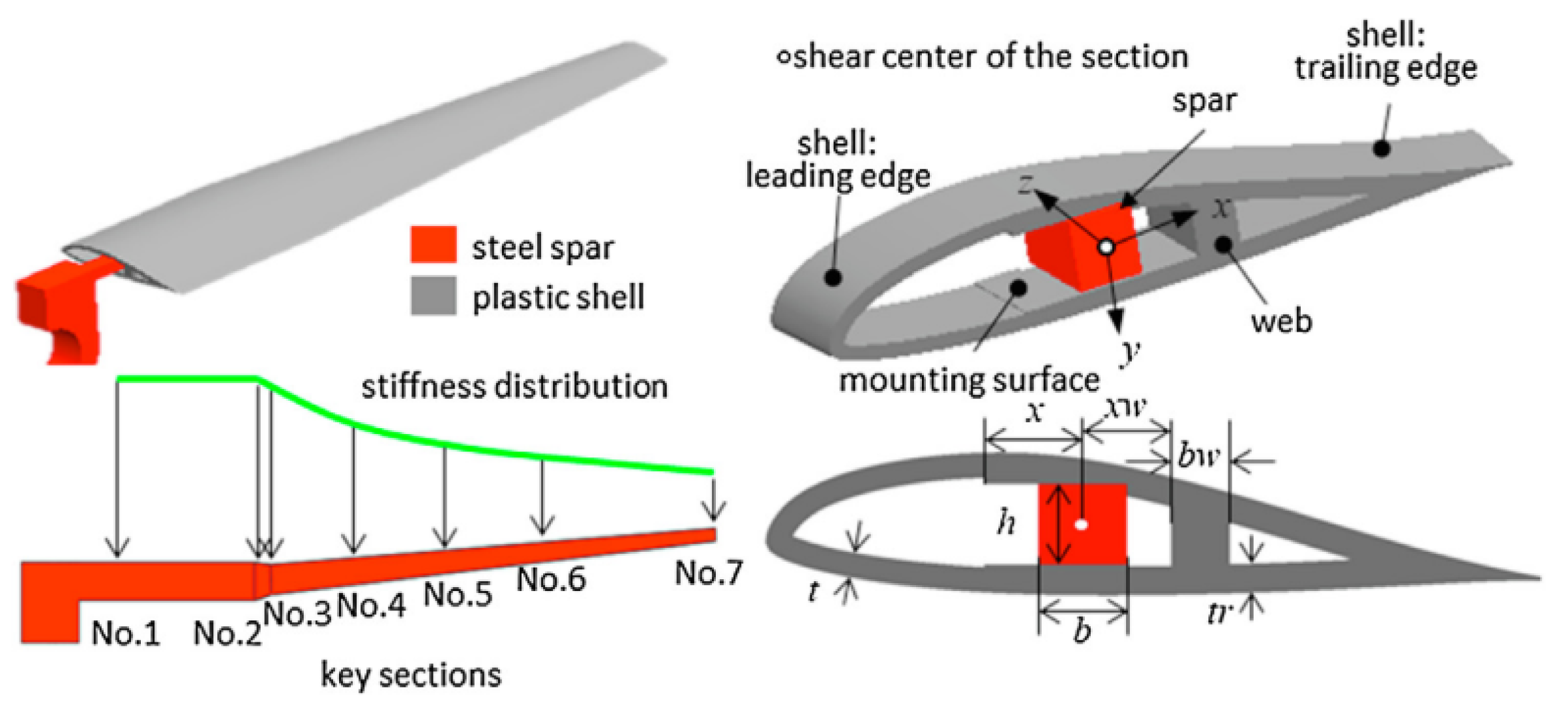
Figure 1. Early static aeroelastic experiment model, Reproduced with permission from [33].
Actuators 11 00309 g001
Figure 2. Static aeroelastic wind tunnel test, Adapt with permission from [43].
Actuators 11 00309 g002
Figure 3. Multi-layer composite plate with delamination, Adapt with permission from [46].
Actuators 11 00309 g003
Figure 4. Same thickness plate, Adapt with permission from [47].
Actuators 11 00309 g004
Figure 5. Single beam of wind tunnel model, Adapt with permission from [48].
Actuators 11 00309 g005
Figure 6. Aerodynamic model of aircraft, Adapt with permission from [28].
Actuators 11 00309 g006
Figure 7. Frame composite structure, Adapt with permission from [50].
Actuators 11 00309 g007
Figure 8. Full-scale wing of aerodynamic, Adapt with permission from [51].
Actuators 11 00309 g008
Figure 9. Photographs of model tests, Adapt with permission from [61].
Actuators 11 00309 g009
Figure 10. Low speed static aeroelastic test of high aspect ratio wing, Adapt with permission from [64].
Actuators 11 00309 g010
Figure 11. Geometry of the swept-wing aircraft, Adapt with permission from [82].
Actuators 11 00309 g011
Figure 12. Original and moved meshes, Adapt with permission from [96].
Actuators 11 00309 g012
Table 1. Comparison of materials properties used in aeroelastic model manufacture.
MaterialTensile Strength (MPa)Tensile Modulus (GPa)Strength (MPa·cm3/g)Stiffness
(GPa·cm3/g)
Density (g/cm3)
Aluminum42072151.125.92.78
Steel (structural)1200206152.926.37.85
Titanium alloy1000116.7221.225.84.52
Glass fiber/polyester composite material124548.262324.12.0
High-strength carbon/epoxy resin1471137.3101494.71.45
High modulus carbon/epoxy resin1049235656146.91.6
Aramid/epoxy resin137378.4981561.4
Publisher’s Note: MDPI stays neutral with regard to jurisdictional claims in published maps and institutional affiliations.