
The Research on Soft Pneumatic Actuators in Italy: Design Solutions and Applications


Department of Mechanical and Aerospace Engineering, Politecnico di Torino, 10129 Turin, Italy
*
Author to whom correspondence should be addressed.
Actuators 2022, 11(11), 328; https://doi.org/10.3390/act11110328
Submission received: 11 October 2022
/
Revised: 4 November 2022
/
Accepted: 8 November 2022
/
Published: 10 November 2022
(This article belongs to the Special Issue Artificial Muscles for Biorobotics: Study, Application and Future Perspectives)
Abstract
:Interest in soft actuators has increased enormously in the last 10 years. Thanks to their compliance and flexibility, they are suitable to be employed to actuate devices that must safely interact with humans or delicate objects or to actuate bio-inspired robots able to move in hostile environments. This paper reviews the research on soft pneumatic actuators conducted in Italy, focusing on mechanical design, analytical modeling, and possible application. A classification based on the geometry is proposed, since a wide set of architectures and manufacturing solutions are available. This aspect is confirmed by the extent of scenarios in which researchers take advantage of such systems’ improved flexibility and functionality. Several applications regarding bio-robotics, bioengineering, wearable devices, and more are presented and discussed.
1. Introduction
The observation of nature and the study of biology have always inspired the design of new technologies and, more recently, new robotic systems which are able to imitate their biological counterpart. Bio-robotics has found application in a wide range of industries over the years. In medicine, it has encouraged the development of minimally invasive surgical techniques [1,2], endoscopy [3], and the design of rehabilitation [4,5,6] and assistive devices [7,8,9] for the disabled or elderly. It has also been employed to explore extreme environments [10,11] and for environmental monitoring, such as inspecting and cleaning the seabed [12,13] and the soils [14].
In most of these applications, the developed devices must safely interact with human people or delicate objects with complex geometries and move quickly in unconventional environments. In this sense, soft robotics is an effective technology. The high compliance of the soft robots, in fact, improves human-machine interaction [15], both in terms of safety and acceptability. For instance, it allows the design of grippers that can autonomously adapt to the object’s shape to be grasped [16].
Soft robots can be actuated by soft actuators. There are many different types of soft actuators, which differ in their working principle. They can use electroactive polymers [17,18], shape memory alloys/polymers [19,20,21,22], hydrogels [23], jamming materials [24,25], electrorheological/magnetorheological fluids [26], or pressurized air [27,28]. The latter is simpler than other driving methods. In addition, pressurized air is a widely available power source in industrial processes, intrinsically safe, clean, low cost and does not involve electromagnetic interference problems.
Soft pneumatic actuators are typically known as Pneumatic Artificial Muscles (PAMs) and, generally, consist of a deformable inflatable chamber that can be reinforced with polymeric fibers [29,30] or inextensible fabrics [31], or stiff rings [32,33]. Depending on the inflatable chamber shape and on how the reinforcement material is arranged on its surface, the pressurization causes chamber expansion in the low stiffness direction which in turn develops a pushing or pulling force and producing axial [34], bending [35,36], or torsional deformations [16]. Therefore, several PAMs can be realized with different functionality, maximum supplying force, and range of movement. On the other hand, PAMs could be subjected to air leakage, and have reduced stroke and a non-linear behavior that requires sophisticated control [37] and the development of analytical models for sizing and choosing the actuator most suitable for the specific application [29,38,39,40]. Despite this, the advantages listed above as well as the modular structure of these actuators have promoted their use in very different fields, attracting scientific interest.
Over the years, several research groups have been developing PAM prototypes and analytical models to predict their behavior. Since 1997 [36], a great effort has also been made in Italy to improve the versatility of the PAMs by designing, developing and testing new geometric shapes and new construction materials. This paper reviews the advancement in PAMs technology carried out by researchers in Italy. Firstly, a classification for PAMs is proposed. Then, some particular applications of each pneumatic actuator type are presented and discussed.
2. Design Features and Functionality of Pneumatic Deformable (Soft) Actuators
The force exerted by the PAM mainly depends on the supply pressure, its geometric shape, and on materials selected. The development of different shaping has allowed for a widespread diffusion of these actuators in different fields. Therefore, a proper PAMs classification can be based on their geometry.
The data selection for this review was restricted to research groups from Italy, by querying the Scopus and Google Scholar databases with the following keywords: soft actuator; pneumatic artificial muscle; soft robotics; deformable actuator; McKibben muscle; bending actuator. Only the studies including the design and/or modeling of pneumatic-actuated devices were included.
As a result of this process, 51 papers were selected. The following typologies were derived: McKibben muscle, straight fibers muscle; linear bidirectionals actuator; bending pneumatic actuator; self-sensing actuator; air-pocket; and bellows muscle. Throughout this section, we will describe each architecture in detail and also provide mathematical modeling when available.
2.1. McKibben Muscle
The braided fiber muscle, also known as the McKibben’s muscle (MKM), is the most common PAM. It consists of a deformable cylindrical chamber, typically made of elastomeric material; two heads that allow fixing and supplying the actuator; an external net of not lengthening fibers wrapped in a helical configuration around the inflatable chamber and anchored to the two heads. The pressurization of the inner chamber causes its radial expansion. Due to the fibers’ inextensibility, the radial expansion is followed by an axial contraction of the actuator that generates a pulling force. MKM behavior is shown in Figure 1. It can be noted that the radial expansion is almost constant along the actuator axis, except for the parts near the ends.
MKM traction force depends on many factors such as the internal radius, the thickness, and the nominal length of the inflatable chamber; the winding angle of the fibers (i.e., the inclination angle between the fiber and the circular section of the actuator); the constitutive materials; the supply pressure and the contraction ratio (i.e., the ratio between the shortening of the actuator and the nominal length) imposed on the muscle. The typical force trend is shown in Figure 2. The tensile force increases as the initial radius, the winding angle, and the supply pressure increase, and the contraction ratio and chamber thickness decrease. On the other hand, high winding angles result in higher deformation of the inflatable chamber. A good compromise to increase the force developed without reaching higher chamber material strain is to achieve a winding angle of about 75° [29].
The relationship between the said parameters and the traction force is not linear. For this reason, several models have been developed to facilitate the choice of the most suitable actuator for the application and the development of appropriate control.
Ferraresi et al. [29] developed a mathematical model in which the actuator was modeled as a homogeneous isotropic tube with constant thickness. They derived the relation reported in Equation (1) by studying the equilibrium and by considering the material and geometric consistency equations.
In Equation (1), E is the Young module of the inflatable chamber; lf and n are the length and the number of coils of the inextensible fiber; p and F are the supply gauge pressure and the tensile force. The cross-section area of the elastomeric wall is computed as presented in Equation (2). The other geometric parameters are shown in Figure 1.
Equation (1) matched the actual behavior of the MKM except for low supply pressures and high loads. These mismatches are mainly related to neglecting the muscle construction imperfections, the friction between the inflatable chamber and the external net, and the non-cylindrical shape of the actuator near the two heads.
To take into account the effect of the rounding of the actuator near the heads, Belforte et al. [38] developed a model based on the virtual work principle, used to compute the traction force as:
In Equation (3), lf is the inextensible fiber total length; t0 is the distance between the projections of point B and point C (Figure 1) in a plane perpendicular to the actuator axis; p and F are the supply pressure and the tensile force. Equation (3) assumes the inflatable chamber as perfectly flexible and with zero thickness, hence it provides an overestimation of the muscle force since it does not consider the energy dissipated to deform the elastic membrane.
To overcome these limitations and evaluate the effect of both the thickness and the rounding of the terminal, Antonelli et al. [39] developed a 3D non-linear parametric finite element model. This model was used as a tool to achieve a formula aimed at predicting the behavior of MKM for a specific material (Dow Corning®, SILASTIC S) of the inner tube and a specific winding angle of the fiber (α = 62°) [41]. One-hundred simulations were carried out by numerical models for several combinations: 4 values of internal radius ([15, 20, 22.5, 25] mm); 5 values of thickness ([1,2,3,4,5] mm); 5 values of contraction ratio ([0, 0.05, 0.10, 0.15, 0.20]). The maximum supply pressure and its incremental step were set equal to 0.25 MPa and 0.01 MPa, respectively. All of the numerical curves can be described by Equation (4):
The values of coefficients Ai,j, Bi,j and Ci,k (i = 1,2,…,6; j = 1,2,3; k = 1,2) are reported in Antonelli et al. [39]. The models from [29] and [39] have been compared to highlight any difference in behavior, due to the different formulations. To achieve this, Equations (1) and (4) have been implemented to evaluate the behavior of a MKM for different values of contraction ratio and supply pressure. The curves obtained with the two models are similar and are shown in Figure 3, highlighting a good agreement between the two models.
2.2. Straight Fibers
Straight fibers muscle (SFM) is externally similar to the McKibben solution, but the deformation of the inflatable chamber occurs in a very different way. As shown in Figure 4, the SFM consists of a rubber tube reinforced with longitudinally arranged inextensible fibers which do not hinder the radial deformation of the muscle. Therefore, the SFM radial expansion is not constant along the actuator axis, and the latter assumes a cask-like shape when pressurized. That allows the SFM to achieve higher contraction ratios and to develop greater forces than the MKM at the same supply pressure but, on the other hand, it reaches the breaking point first [29]. The elastomeric chamber generally breaks close to the fibers due to mechanical stress. A first stress component is tensile stress due to circumferential muscle deformation. The other one is compressive stress, related to the supply pressure, applied between the fiber and the internal surface of the chamber [42]. In some cases, rigid rings divide the muscle into several sectors of equal length to reduce bulge and circumferential stress.
As well as for MKM, mathematical models have been developed to predict the behavior of SFM to varying physical (e.g., materials of tube and fibers, number of fibers N, number of rings Nr, muscle resting radius r0, muscle resting length l0, and tube thickness s) and functional parameters (e.g., supply pressure p, contraction, developed force F, and diameter deformation).
Ferraresi et al. [29] modeled the SFM as a tube of homogeneous and isotropic material having given Young modulus E. The tube is reinforced by N inextensible fibers having cross-section Af, initial length lf and Young modulus Ef. The fibers are connected to the heads of radius rh. Moreover, the cross-section of the deformed chamber is assumed to be circular with radius R and central angle φ. Finally, they derived the equations of static equilibrium of a single segment muscle along the direction parallel to its axis (Equation (5)) and the perpendicular one (Equation (6)):
In Equations (5) and (6), T is the tension in each inextensible fiber. The numerical solution of Equations (5) and (6), of the characteristic fiber equation (Equation (7)), and of the equations imposed to respect the geometric consistency of the muscle (Equations (8) and (9)) allows for the evaluation of the SFM’s tensile force for given supply pressure and length.
The relationship between the said parameters and the tensile force is shown in Figure 5; the force increases with the initial radius, the nominal length, and the supply pressure while decreasing with the contraction ratio and thickness of the chamber.
Due to the nonlinear rubber’s constitutive law, Durante et al. [40] preferred to develop an axisymmetric numerical model to describe the SFM behavior. The inner tube (r0 = 15 mm; s = 0.1 mm; E = 70 MPa) was described by the first-order Mooney-Rivlin model (C10 = 0.0694; C01 = 0.0628), while each inextensible fiber (made in glass fiber, Ef = 70,000 MPa; Af = 0.44 mm2) was treated as a single line of truss of equivalent axial stiffness. Twenty-seven different simulations were performed by varying the resting length of the muscle, the supply pressure, and the applied load to extrapolate the relationship between the characteristic parameters of the muscle and the generated force. The results of the simulations were used to create a correlation graph that relates the dimensionless parameters π1, π2, and π3:
The correlation graph can be used to obtain the static muscle characteristic of an SFM with known r0, l0, and s.
A particular type of SFM is the textile actuator designed at the Politecnico di Torino (Turin, Italy) in 2012 [43,44]. The prototype consists of an inner latex tube covered with two strips of orthotropic fabric sewn together with a cotton thread. The fabric used is a trilaminate fabric with two outer polyester layers and a breathable polyurethane inner membrane and is rigid in one direction and deformable in the perpendicular direction. Despite the seam lowering the breaking load (Fmax = 11 N), the overall characteristics of this actuator have revealed it to be suitable for integration into active garments to assist the upper limbs of an individual. It should be noted that the friction between the tissue layer and the latex tube makes it necessary to pressurize the muscle over a certain threshold before the prototype starts to contract. Generally, the thicker the latex tube, the higher the pressure that must be reached before it begins to contract. Finally, the friction between the two layers causes relevant hysteresis between the inflation and deflation cycles.
2.3. Linear Bidirectional Actuator
Both MKM and SFM only exert tensile forces. As a result, two actuators in an antagonistic configuration are needed to apply a double-effect actuation, hence increasing the bulkiness and complexity of the actuation mechanism. By analyzing of the literature, it has been shown that three different actuators have been designed and developed to overcome this limit.
The first one is BiFAc [45], developed at the Politecnico di Torino and shown in Figure 6a. It is a deformable fluid actuator consisting of three coaxial cylindrical rubber membranes linked to two rigid end plates. The central and external membranes are reinforced with longitudinally oriented inextensible fibers, while the intermediate membrane is reinforced with inextensible fibers oriented in a circumferential direction. As a consequence, all the membranes are inextensible along the direction of the fibers and compliant elsewhere.
The presence of three coaxial membranes involves the generation of three different chambers supplied by three ports: if the intermediate chamber and the outer chamber are simultaneously supplied, the muscle contracts; on the contrary, by pressurizing the central and the intermediate chamber, the muscle extends.
The force F exerted by BiFAc depends on the supply pressure p; the geometric characteristics of the muscle (length Lf and nominal radius r of the membranes and the active length L of the actuator); the angle of curvature φ (see Figure 4 for reference) of the membrane in working position. The value of the total force exerted by the actuator can be obtained from the forces’ equilibrium of the end plate:
In Equation (11), subscript c, i and e indicate the central, intermediate, and external chambers, respectively.
Another prototype bidirectional deformable actuator developed by Italian researchers is PATuCCo [46], a double-effect linear cylinder with tunable compliance constraints (Figure 6b). The actuator consists of a piston connected to a cylindrical chamber through two rolling membranes mounted in opposite directions. The volume of fluid contained within the two membranes constitutes chamber A. Pressurizing the latter allows for the variation of the stiffness in the not-actuated direction. Chamber C, on the top, is open and at atmospheric pressure (pc); chamber B, bottom, is pressurized at pressure pb. The differential pressure between chamber B and chamber C causes the piston motion.
Finally, the multifunctional pneumatic muscle [47] was born from the collaboration between Scuola Superiore Sant’Anna (Pisa, Italy), Istituto Italiano di Tecnologia (Genova, Italy), and the Arctic University of Norway. The actuator has a structure similar to the McKibben. It consists of an internal latex tube covered by an external PET net whose fibers are wound in a helical configuration. The inner latex chamber is connected to two heads; the first head is connected to one extremity of the external net, while the second head is provided with a longitudinal stem. The other extremity of the external net is attached to a slide that is able to move along the stem. The user can modify the net wrapping angle α (see Figure 1 for reference) by positioning the moveable slide. Angle α greater than 36° enables the muscle to expand radially and contract axially; on the other hand, if alpha is less than 36°, the muscle reduces radially and extends axially; finally, when alpha is equal to 36°, the muscle does not modify its length, but increases its stiffness as pressure increases. The performance of multifunctional muscle is mainly affected by the diameters of its heads. As the diameter increases, both the force developed and the actuator displacement decrease during the contraction state, while, in the extension phase, the force and the deformation increase. It is possible to reach a good compromise between the performance in the two different states with a diameter of 24 mm. Finally, the generated force and the axial deformation increase with the length of the internal chamber.
2.4. Bending Pneumatic Actuator
A compliant end-effector, able to grasp objects of different sizes and shapes and at the same time guarantee a safe human-machine collaboration, is fundamental for collaborative robots. A feasible solution to the problem is the implementation of single or multiple bending pneumatic actuators (BPAs), which bend as the supply pressure increases. The core of BPA is an elastomeric tube that can be made up of a single internal chamber or divided into two or three longitudinal chambers.
In the first case, a flexible and inextensible lateral reinforcement prevents the elongation of the BPA and causes its bend. An example is represented by a pneumatic finger made by Carello et al. [35]. The prototype, shown in Figure 7a, consists of an inner tube of elastomeric material, a leaf spring, and a flexible external tube. All three elements are connected to two heads. As the supply pressure increases, the inner tube tends to expand radially and axially. However, radial deformation is prevented by the external tube, while axial deformation is hindered only by the presence of the flat spring. Then, the BPA is forced to bend into a plane containing the spring.
On the other hand, the prototype developed by Antonelli et al. [48], shown in Figure 7b,c consists of an internal tube in hyper-elastic silicone rubber wrapped in a polyamide inextensible square-mesh gauze. The latter has some cuts perpendicular to the actuator axis, which guide the bending of the actuator. The kinematics of the actuator and the bending angle θ depend on the supply pressure p, the diameter and thickness of the inner tube, and the geometry of the gauze cuts (the angular extension of the uncut sector in correspondence to the cut region α; the axial length of the cut openF) according to the predictive formula given in Equation (12):
The diameter and thickness of the inner tube were equal to 20 mm and 2 mm, respectively. Antonelli et al. [48] developed a numerical model to find the predictive formula. Twenty-five simulations were performed to evaluate θ to varying α, openF, and p.
A BPA analytical model was instead developed by Cacucciolo et al. [30]. In this case, the BPA consists of an inner silicon rubber cylinder connected to two heads and wrapped by an inextensible fiber. The design of the actuator, shown in Figure 7d, is similar to that of MKM and SFM, but the fiber wrapping angle is less than 30°, so the actuator tends to privilege axial expansion rather than the radial one. The expansion is partially hindered by a high-density polyethylene fabric which acts in a similar way to the leaf spring used by Carello et al. [35]. Assuming that the curvature of the BPA is constant along its axis, Cacucciolo et al. [30] described and solved the kinematics of the actuator and finally wrote the equilibrium equations in the deformed configuration. The supply pressure that guarantees the equilibrium is then evaluated.
As mentioned above, the inner tube of the actuator can be divided into two or three longitudinal chambers. In this case, differentiating the power supply of the chambers, the BPA bends. However, the chambers must be separately actuated, and it is necessary to prevent fluid flow from one compartment to another, by means of special inserts housed in each chamber end [36].
The two-chamber BPA from Politecnico di Torino [32,49], shown in Figure 8a, consists of a rubber tube divided in two by a longitudinal wall. The rubber tube is reinforced with several metal rings to prevent the radial deformation of the muscle. By supplying the two chambers at different pressures, the actuator bends in a plane perpendicular to the longitudinal wall; on the other hand, by imposing the same pressure on the two chambers, the actuator deforms axially. The workspace was investigated thanks to a special test bench, where one end of the actuator was linked to the frame, while the end-effector was connected to four inextensible wires that were wrapped on the shafts of as many multiturn potentiometers, in turn mounted on the frame. By measuring the free length of the wires, the end-effector position was calculated. The workspace of a two-camber BPA (tube external radius = 27.5 mm; wall thickness = 4 mm; nominal length = 350 mm) is shown in Figure 8a. When chamber 1 is supplied with 4 bar pressure, the end-effector moves from point A to point B. At this point, supplying chamber 2 and maintaining chamber 1 pressure, the end-effector moves from point B to point C. By discharging chamber 1, the CD trajectory is obtained. Finally, by discharging both chambers, the end-effector returns to point A.
Figure 8b shows the three-chamber BPA from the same researchers [36], in which the chambers are equally spaced radially. When one chamber is actuated, the BPA bends in the longitudinal plane containing the centroid of the chamber. When two chambers are supplied at the same pressure, the BPA bends on the intermediate longitudinal plane between the two chambers with a radius of curvature greater than in the previous case. Finally, pressurizing all three chambers at the same pressure, the actuator expands axially. The workspace of the prototype (external radius = 3 mm; nominal length = 350 mm) is shown in Figure 8b and was measured through the test bench previously described. For this actuator, an analytical model which was able to calculate the bending angle as a function of the supply pressures of each chamber (p1, p2, p3) was derived [36]:
Equation (13) provides a theoretical calculation that does not take into account real aspects such as manufacturing inaccuracy, material viscoelasticity, chamber deformation during actuation, etc. Therefore, to control the position of the end-effector, the presence of internal sensors is required. This solution was adopted in Belforte et al. [50] and Ferraresi et al. [51], and detailed in Section 2.5.
STIFF-FLOP [25,52] is a particular type of 3-chamber BPA that integrates a stiffening mechanism based on granular jamming. At the center of the three actuation chambers, there is a latex membrane filled with coffee. As soon as the vacuum is applied, the density of the chamber and stiffness of the STIFF-FLOP increase. Therefore, the actuator behavior can be tuned to adapt to the external environment. Assuming constant curvature, Ranzani et al. [25] have developed an analytical model to predict the angle of bending β of the actuator as a function of geometrical parameters:
In Equations (14)–(17), α is the angle between the bending plane and the center-chamber centroid segment; r is the curvature radius; E is the Young modulus; I is the moment of inertia; Ap is the total pressurized area of the cross-section; d is the distance between the central axis of the actuator and the chamber centroids; L is the final length of the actuator; L0 is the rest length of the actuator; A0 is the total base area of the cross-section.
A multimodule actuator can be realized by composing multiple STIFF-FLOP [53]. The junction must not alter the actuator’s general behavior, so it contains the stiffness chamber and is realized in a stiffer silicone than that which is used for the internal chamber, with low length/diameter ratio. Another important aspect is the independent power supply of the two modules. The power supply tubes reach the distal module by passing through the proximal one, so they must be flexible enough to allow the actuator to move. It is also obvious that the size of the tubes limits the number of modules that can be connected to each other, with a maximum of four modules assembled.
2.5. Self-Sensing Actuator
As a result of the non-linear behavior and the compliance of PAMs, proper sensors should be embodied to monitor their deformation without hindering the actuator movement or increasing the overall encumbrance of the system. To this end, self-sensing PAMs that include the sensing element are spreading.
The detection of the end-effector position for the three-chamber BPA previously described was obtained by measuring the lengths of 3 generatrixes of the cylindrical tube radially equidistant from each other [51]. The sensors could be linear potentiometers, strain gauges, or little silicon tubes containing mercury. In all cases, the sensors must be attached to the chamber wall and arranged along the three generatrixes: as the pressure in the chamber increases, the sensors stretch, and their electrical resistance change. The actual end-effector position could therefore be used as feedback for closed-loop control.
A similar approach is also employed by Lorenzon et al. [54]. The authors developed an actuator consisting of a cylindrical inflatable chamber, two heads, and a reinforcement structure. The reinforcement structure is made up of a conductive polymeric wire inserted into a silicone tube doped with carbon particles, and it is helically wrapped around the inflatable chamber. The winding is facilitated by helical groves present on the external surface of the inflatable chamber. Finally, a silicone outer layer covers the reinforcement structure. The reinforcement structure has two functions: it prevents the radial deformation of the actuator and, at the same time, provides a measure of the actuator’s axial elongation. The electrical resistance of the wire increases as the wire is stretched, and its variation can be used as a strain measure.
2.6. Air-Pocket
Air-pocket (AP) is an inflatable bladder that transforms the air energy into a mechanical pushing action generating distributed forces along the entire contact surface. The output force depends on both the pressure inside the bladder and its shape. Several applications in the clinical and rehabilitation fields have been realized using such actuators.
As a first approximation, the AP can be modeled as two chambers with variable volumes which are connected to each other by a pneumatic resistance [55,56]. This solution allows for simulating the increase in chamber stiffness that occurs during inflation.
As shown in Figure 9, several prototypes of APs have been developed that differ in their shape and materials. In all cases, the AP efficiency depends on how much energy is transferred in the desired direction. For this reason, the bladder should expand only towards the point of interest, and the chamber walls should not generate high elastic resistance.
Manuello Bertetto et al. [57] proposed a textile AP (Figure 9a). The active chamber is made with a piece of fabric rolled on itself and sewn. Medical Windtex® is chosen for the construction, which is an elastic tissue made up of three layers, polyester, polyurethane, and polyester again. The active chamber is attached to a flexible but inextensible shell made up of Aqualight® 160D R to ensure that the AP deforms only on one side. A critical aspect of this actuator is the presence of seams that do not guarantee the perfect tightness of the chamber.
Antonelli et al. [58] designed a squared shape AP made in silicon rubber (Figure 9b). The unidirectional deformation is guaranteed by incorporating a metal plate inside one of the two walls. A thick layer of silicone rubber (3 mm) is first poured into a square mold. After the catalysis, a metal plate is placed on the newly formed layer, and a thinner (1 mm) layer of silicone rubber is poured over it. After the catalysis, a sheet of paper is placed on it, and a last thick layer of silicone rubber is cast. The last layer is drilled, and an air valve is fixed to the layer by a nut to allow for air inlet and outlet.
Mannella et al. [59] have made APs consisting of a cylindrical (or hemispherical) elastomeric membrane clamped to a rigid lower block (Figure 9c). The membranes have been fabricated in liquid silicone that was poured into a special mold and placed in a vacuum chamber to reduce the likelihood of air bubbles. The lower block presents a cavity and a nozzle to allow for the pressurization of the actuator. By comparing the two AP shapes (cylindrical and hemispherical), it emerged that the cylindrical AP allows for higher displacements with less material stress.
2.7. Bellow Muscle
Bellow muscle (BM) is a deformable pneumatic actuator whose shape resembles an accordion. Thanks to its shape, it can stretch very much compared to its resting size. Distinct from MKMs or SFMs, whose maximum contraction ratio is about 20–40%, BMs can reach 900% of their resting length even at low supply pressures (<1 bar). Belforte et al. [31,60] developed a four-chamber textile bellow muscle assembling six circular textile rings and two textile disks obtained by cutting them from a three-laminated fabric with three polyester layers. The external and internal edges of the fabric rings are glued to each other. The upper and bottom ends of the muscle are obtained by gluing the external edge of the two textile disks with the external edge of the first and the last ring, respectively. Finally, the textile disks are also connected to two metal disks necessary to link the muscle to the environment. The textile BM prototype is shown in Figure 10.
As soon as the BM is pressurized, it expands longitudinally and at the same time reduces its radial size. Elongation increases with increasing supply pressure and decreases with increasing compressive load.
3. Applications
The availability of PAMs in different sizes, and shapes, as well as the possibility of exploring different types of movement and adjusting the internal pressure to obtain different acting forces, allow for a wide customization of the behavior of these actuators. Versatility combined with high power/weight ratio, ease of assembly, inherent safety, and cost savings, have encouraged the spread of PAMs in various fields of application, ranging from robotic manipulation to bio-inspired robots to medical devices. The following section will describe some of the applications developed in Italy.
3.1. Clinical Investigation and Medical Research
Air-pocket actuators can be used to develop Intermittent Pneumatic Compression (IPC) devices able to impart controllable and tunable mechanical stimuli on the patient’s limb and to study and monitor vascular hemodynamic phenomena such as the hyperemic response and the patient’s volemic status. Ferraresi et al. [55] designed a single-chamber IPC device based on the actuation of an inflatable cuff communicating with a pressure transducer. The device is filled with pressured air through two 2-way digital solenoid valves for quick charge and discharge; a pressure-proportional valve is added for accurate control, made possible by a PID controller. The use in parallel of digital valves and a compact proportional pressure valve allowed for quick charge and discharge of the actuator and, at the same time, accurate control of the set constant pressure value. This setup allowed for the use of the single-chamber IPC device to generate complex profile stimuli required for this kind of hemodynamics study.
The wide variety of stimuli that can be delivered could help investigate several vascular phenomena, such as the rapid hyperemia occurring due to mechanical stimulation of a limb [61], or the attenuation of the hyperemic response after repetitive stimulation [62].
The single-chamber IPC device was also used to non-invasively measure the average velocity of a pulse-induced wave propagating along a vein, the so-called venous pulse wave velocity vPWV [63,64]. The measurement of pulse wave velocity PWV in arteries is a cardiovascular health index, and it is related to vessel stiffness and blood volume losses [65,66]. On the other hand, the measurement of pulse wave velocity along a vein could provide objective information on the volemic status of a patient. However, the lack of natural pulsatility and the low venous pressure make the evaluation of the venous PWV very challenging. The IPC technique is used to artificially generate venous pressure pulses through a rapid compression of the foot [63] or the hand [64], as shown in Figure 11. This technique could be used for long-term patient monitoring and early detection of excessive fluid depletion in patients undergoing dialysis.
3.2. Treatment of Cardiovascular Diseases
IPC devices are also employed to replace the muscle pump effect in bed rest patients to promote venous return, increase the End Diastolic Volume (EDV), and improve tissue perfusion. In this sense, they are suitable for treating cardiovascular diseases such as venous ulcers or reducing the risk of deep vein thrombosis.
Ferraresi et al. [67] developed a multi-chamber IPC device constituted of six textile air-pocket integrated within two shells (one mounted on the calf and the other one on the foot of the patient), six 3-way electro-pneumatic valves, six pressure sensors (one for each air-pocket), and a programmable logic controller. The latter issued sequential compressions that imitate peristaltic contraction along the patient leg. Finally, a PID controller regulated the supply pressure of the chambers [68]. The six-chamber IPC device is shown in Figure 12. The device’s ability to simulate the physiological muscle pump was demonstrated by comparing the hyperemic responses due to mechanical compression and the electrical stimulation of the same muscle. The two hemodynamic responses were equal in terms of both blood flow and tissue oxygenation index, suggesting a common fundamental mechanism related to the mechanical deformation of the blood vessel [61].
Maffiodo et al. [69] developed a lumped parameters model of the cardiovascular system of a pathological subject affected by diseased lower limb circulation and assisted by the six-chamber IPC device. The simulation showed that the IPC treatment restores the physiological ejection fraction, cardiac output, and ventricular stroke work value. Subsequently, the mechatronic device was tested on 19 healthy subjects. Their thoracic electrical bioimpedance decreased on average by 1.3% due to the increase in the thoracic blood volume after compressive stimuli [57]. Although the EDV was not measured in this study, based on previous similar studies [70], it can be speculated that it increased by about 10%.
Bed rest patients can suffer from pressure ulcers. Intense and prolonged pressure can occlude the blood vessels and causes the concentration of toxic substances that damage the surrounding soft tissues. Recently, Mannella et al. [59] designed a prevention ulcer cushion consisting of four concentric surfaces, each associated with a different risk zone. The surfaces are constituted by many cylindrical APs (diameter = 30 mm; height = 65 mm; thickness = 1.2 mm). Each level surface is connected to two digital valves, one to inflate and the other to deflate the actuators, and to a pressure sensor. The latter detects the cushion-body interface pressure. The system is completed by a controller that monitors the pressure values of the four surfaces and deflates the APs corresponding to the highest-pressure concentration zone while simultaneously inflating the APs belonging to the lowest pressure concentration zone. The cushion can be integrated into a reclining chair [71].
3.3. Minimally Invasive Surgery
Minimally invasive surgery (MIS) reduces the extent of incisions, hence the risk of infection, and the patient hospitalization time. The main MIS techniques are laparoscopic surgery, natural transluminal endoscopic surgery (NOTES), and robotic surgery.
Laparoscopic surgery involves a laparoscope and other miniaturized surgical instruments. Laparoscopic instruments are introduced into the body through 1 or 2 cm incisions and consist of a small rigid tube connected to the handle used by the surgeon to guide the device and to the end-effector. The latter could be scissors, grippers, clamps, etc. NOTES involves a natural orifice to introduce the device into the body. Due to the high distance between the end-effector and the entrance natural orifice, active degrees of freedom are required to allow for large and well-controlled movements of the device along its path. In addition, the device should adapt its stiffness to the surrounding environment to avoid damage to soft tissues. Finally, robotic surgery involves a multi-degree of freedom robotic arm able to reproduce the movement of the clinician. The robotic arm is remotely guided by the surgeon using a haptic interface, which gives the operator feedback on the pressure exerted by the device on the patient body. Over the years, PAMs have been successfully employed to develop both flexible NOTES manipulators and haptic interfaces.
De Falco et al. [1] developed a multimodule soft manipulator inspired by an octopus arm. The manipulator can elongate, bend, squeeze and separately change the stiffness of each single-module unit. All these characteristics allow the manipulator to safely move inside the patient’s body, move around an obstacle, move an organ away from the operative site, and so on. The soft multimodule manipulator, shown in Figure 13a, consists of three STIFF-FLOP actuators [25], one micro-camera, and one pneumatic gripper that can apply a maximum grasping force of 2.5 N. The system is completed by nine 3/2-way air valves (one for each active chamber) to actuate the manipulator; one 5/2-way air valve to actuate the pneumatic gripper; one air compressor to supply the 3 STIFF-FLOP actuators and the gripper; one vacuum pump to modulate the stiffness of the manipulator; two air-filters for the compressor; a voltage power supply.
The STIFF-FLOP actuator was previously described in Section 2.4. With reference to Figure 13b, the actuation system of the pneumatic gripper [72] consists of two pneumatic antagonistic actuators (1) made by a rigid hollow cylinder closed by a flexible membrane. The two actuators act on a body constrained by a prismatic joint and connected to the transmission system (3) through a rod (4). The transmission system consists of two symmetrical slider-crank-coupler linkages that transform the linear motion of the rod into the gripper opening angle. A linear transducer mounted on the transmission system measures the rod displacement. By activating the bottom actuator, the rod moves toward the transmission system and causes the opening of the gripper; on the contrary, if the upward actuator is pressurized, the rod moves in the opposite direction, and the gripper closes. Finally, it is possible to regulate the gripper stiffness by supplying both actuators simultaneously.
The minimum supply pressure required to activate the gripper is 0.8 bar, while the maximum opening angle is about 68°. The total length of the manipulator is 253 mm, and it can elongate to about 88 mm, while the maximum bending angle is about 248 degrees. Finally, the total stiffness of the manipulator can be increased by about 80%.
Concerning robotic surgery, Franco et al. [2,73] developed the haptic finger shown in Figure 14. The device consists of a four-bar linkage mechanism rotating on a sagittal plane. Proper sizing of rigid links is essential to ensure a physiological movement of the operator’s finger which is in contact with fingertip support connected with the coupler. The actuation system consists of a McKibben muscle mounted in parallel with a spring, and it is connected to a polyethylene fiber tendon that wraps around a pulley and joins the coupler.
The haptic finger is completed by an encoder that detects the rotation angle of the mechanism; a force sensor that measures the support-finger interaction force; a pressure proportional pneumatic valve and a controller to manage the actuator activation. In the work of Franco et al. [73], the operator interacts with a virtual object and is subjected to haptic feedback. The encoder output and the stiffness model of the virtual object are assumed as the inputs of the control system. Each angle value corresponds to a finger-support interaction force that must be compared with the sensor-measured force. The force error represents the input of the proportional controller that outputs the control signal for the proportional pressure valve.
3.4. Rehabilitation and Wearable Device
Thanks to the high power/weight ratio and the possibility to easily vary the exerted force by adjusting the supply pressure, PAMs are suitable for integration into devices aimed at the treatment of medical conditions, loading reduction, and retrieving the physiological range of movement of the joints. For example, the haptic finger device previously described and shown in Figure 14 has also been proposed in a different configuration as a rehabilitation device to retrieve the physiological finger range of movement [74]. In this configuration, the actuation drives the finger joints in the desired positions with selectable dynamics, according to a protocol that shall be defined by the therapist. Moreover, several PAM-based exoskeletons, orthoses, and wearable devices have recently been developed. The natural compliance of such actuators can also be considered as a driving factor in their adoption within human-machine interaction.
Antonelli et al. [58] developed a scoliosis brace based on the global thrust method. Contrary to traditional braces, the pneumatic brace, shown in Figure 15a, acts on the entire rib cage and not only on three spine points. The device consists of a patient trunk-modeled shell. The inner surface of the latter is covered with air-pockets. Each AP has a surface area of 80 × 80 mm and applies a 25 N pushing force at maximum operating pressure (0.56 bar). The number and the position of the APs depend on the patient’s scoliosis curvature. A grid of holes on the rear of the shell allows for the housing of the supply pipes.
A less disabling but widespread pathology is the low back pain that can be alleviated through massage therapy or a load reduction on the lumbar spine. Antonelli et al. [75] developed a pneumatic device for the massage treatment of the low back. The massage device, shown in Figure 15b, consists of three polymer modules, one upper, one central, and one lower. The upper and the lower module are hinged to the central one. In addition, their lateral edges are connected to two internal aluminum supports. The latter can move along a horizontal axis and rotate both around a horizontal axis and a vertical axis. Each support contains six air-pockets arranged on two columns and is hinged to one external support. The latter can rotate around a vertical axis and contains six air-pockets. The numerous degrees of freedom of the structure ensure the body-actuator contact, while the presence of a harness makes it easy to wear. The air-pockets aim to simulate the pressure exerted by the therapist’s thumb during the massage. Therefore, they have a 34 × 26 mm surface area and apply a maximum force equal to 24 N at 1 bar supply pressure. The massage treatment is applied by sequential activation of the actuators managed by 3/2-way air valves, PLC controller, and air compressor. The number of required valves depends on the massage technique. Six valves are sufficient to obtain a massage in the longitudinal direction, one for each row of actuators. Eight valves are needed to achieve a massage in the transverse direction, one for each column. Finally, 48 valves, one for each actuator, are required to applicate concentrated forces.
Raparelli et al. [76] developed a lumbar orthosis to apply a traction force up to 400 N on the lumbar spine to reduce the spine load. Two five-chamber bellow muscles actuate the orthosis. Each actuator is housed between two non-metal frames: one upper, linked to the user trunk, and one lower, positioned on the iliac crest. Pressurizing the actuators generates a traction force on the spine that increases as the supply pressure increases and decreases as the bellow muscle (BM) elongation increases. Supply pressures below 0.5 bar are sufficient to obtain the desired traction forces. Therefore, the employed BM can be actuated by manual pumps.
Durante et al. [77] designed an active exoskeleton to assist the users in lifting weights and preventing lower back pain. The exoskeleton, shown in Figure 15c, consists of two structural parts. The first is connected to the trunk, while the second is connected to the pelvis. The two parts are connected by a hinge. The exoskeleton is actuated by two MKMs (290 mm in length, 30 mm in diameter). The MKMs are mounted on the rear of the exoskeleton with the upper extremity connected to the trunk’s structural part, and the lower extremity connected to the pelvis structural part. Pressurizing the MKMs generates a torque that helps the user’s back extension. The control system consists of an Arduino, EMG sensors, and an algorithm that manages the air supply of the MKM accordingly to the signal activity of the erector muscles. Durante et al. [77] developed a multibody model to simulate a 25 kg lifting task. The results showed that the exoskeleton reduces the compressive load on the rachis and the anatomical muscle force by about 35% and 43%, respectively.
Figure 15.
Rehabilitation and wearable device. (a) scoliosis brace [58]; (b) massage device [75]; (c) active exoskeleton for the back [77]; (d) passive exoskeleton for upper limbs [78,79]; (e) active suit for upper limbs [80].
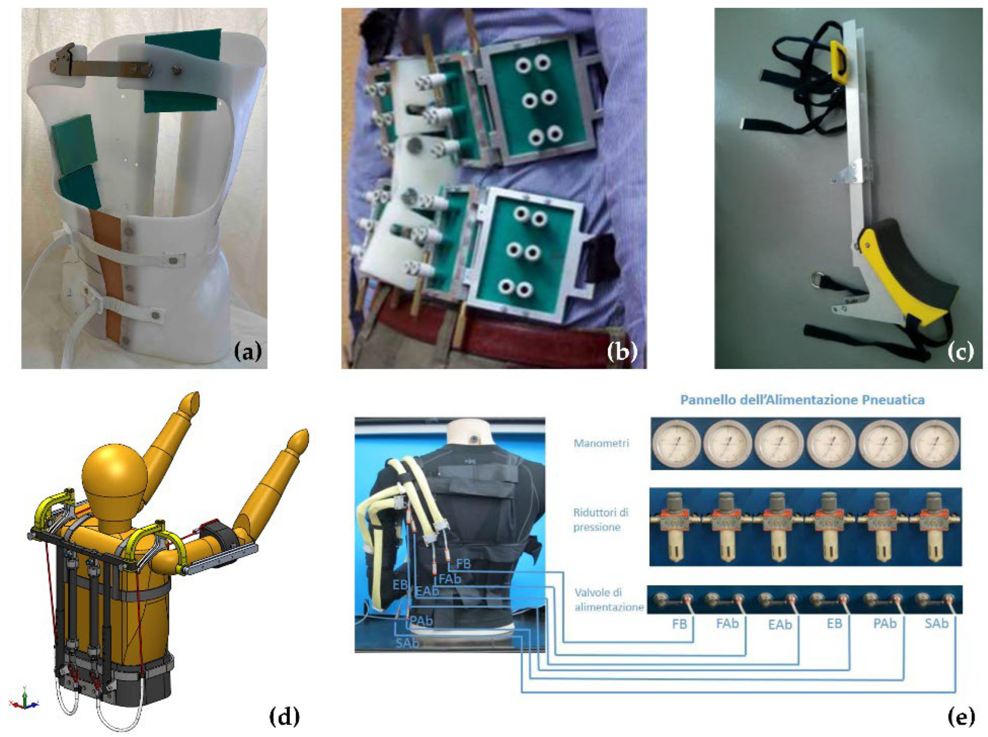
Due to their characteristics, PAMs can also be employed as passive elements (no actuation) within the structure of an exoskeleton [78,79]. The authors designed a passive upper limb exoskeleton based on MKMs to assist workers in keeping their arms in an elevated position (Figure 15d). The exoskeleton improves the performances of workers in repetitive and heavy tasks and reduces the risk of developing a musculoskeletal disease which entails a high cost for the industry and reduces the workers’ quality of life. The gravitational torque on shoulders is balanced by two MKMs positioned on the user’s back. The upper end of each actuator is connected to the exoskeleton frame, and the lower one is connected to a cable that wraps around a shoulder pad and joins the bracelet that supports the user’s arm. The shoulder pad has a cam-like profile and is centered in the shoulder joint; on the other hand, a universal joint connects the exoskeleton arm to the frame to allow flexion/extension and abduction/adduction of the shoulder. The cam radius and the lever arm of the MKM force grow as the flexion angle of the shoulder joint increases. This trend balances the reduction in the maximum force exerted by the MKM due to its contraction extending the workspace. The exoskeleton provides the user with 74% of the torque needed to maintain a shoulder flexion angle between 90 and 120 degrees. In addition, by adjusting the MKM pressure, the exoskeleton can adapt to the user’s weight and to different operating conditions.
Finally, thanks to their compliance, PAMs can also be used without any rigid support frame. For example, Belforte et al. [80] developed an active suit, shown in Figure 15e, made of six textile MKMs anchored on a t-shirt. The MKMs positions recall the anatomical patterns of the muscles responsible for anteposition of the hand, flexion-extension, and pronation-supination of the forearm. The prototype is designed to assist the user during upper limb rehabilitation. The textile bellow muscle has also been employed to develop an upper limb rehabilitation active suit [60].
3.5. Other Applications
Three other applications not strictly related to the human-machine interaction topic will be presented in this section. We are referring to a fruit-harvesting hand, a fish-like robot, and a variable Remote Center of Compliance (RCC) device.
Carello et al. [35] developed a fruit-picking hand shown in Figure 16. The hand is made of three single chamber bending actuators fixed on a base at 120° from each other. The BPAs have been dimensioned to grasp fruits with a diameter between 70 and 110 mm without colliding with each other.
Although the authors designed the soft robotic hand to harvest delicate fruits, the device can also be employed to promote industrial automated production iterations, such as automatic sorting and packing of irregularly shaped or fragile items.
Ferraresi et al. [33] developed a biomimetic fish-like underwater robot to inspect dangerous and hostile environments. The fish robot, shown in Figure 17, comprises three parts: the tail, the rear body, and the anterior body. The tail, which reproduces a carangiform caudal fin, is linked to the rear body through a hinge. The rear body is a cone-shaped two-chamber bending actuator. The other end of the actuator is rigidly connected to the anterior body. The latter is provided with a hollow chamber that contains the equipment needed for the functioning of the robot.
Starting from the PATuCCo actuator, previously described in Section 2.3, Bottero et al. [81] developed a method to identify and modify the RCC position of the device, depending on supply pressure and stroke. The study was conducted by means of a FEM model, comprising the external aluminum cylindrical wall and the rolling diaphragm, the latter modeled using the Mooney-Rivlin model. The simulations were performed imposing several values of stroke and of supply pressure, while a 5 N horizontal force was applied at 5 different piston points. This study allows for the use of this device in soft robotics applications where it is necessary to modify and control the compliance characteristics of the end effector. Devices developed with the RCC concept are generally employed in precise assembly industrial operations, such as inserting pegs into holes or screws into threaded cavities.
4. Discussion and Conclusions
In order to provide a synthetic overview of the activities produced by Italian researchers on deformable pneumatic actuators, a classification based on typologies and applications is proposed, resulting in 51 papers published between 1997 and 2022. For sake of clarity, a classification table (Table A1) summarizing all of the papers reviewed is presented in Appendix A. Of course, being focused only on Italian studies, this review cannot cover the whole of the work carried out on soft pneumatic actuators. Nevertheless, all of the activities carried out in Italy and reported in this work presents a relevant picture in this field, as concerns both the number of original solutions and the variety of applications. Despite being focused only on the Italian scenario, this manuscript clearly shows that this research has received increasing interest from researchers, and the outcomes provide information that can be of relevant interest in worldwide.
As shown in Figure 18a, 49% of the cited articles have been published in the last five years, testifying to a renewed interest in this technology, which may be related to the recent spread of soft robots. The latter involve safer interactions with humans and the external environment and serve several functions in medical and industrial applications. In most of the papers (67%, see Figure 18b), an analytical or numerical model used to describe the functionality of the PAM is presented. This is likely due to the highly nonlinear behavior of most of the solutions proposed, yet both the actuator’s design and control can take advantage of such models to optimize the result and fulfill the requirement specifications of each application. For actuator closed-loop control, proper flexible sensors should be integrated without hindering the actuator movement or increasing the overall bulkiness of the system. Tubes filled with liquid metal, semi-conductive polymer, magnetic and piezoelectric sensors, and optical fibers are generally used as sensing elements [37]. However, there is still much to investigate in the field of flexible sensors to improve their reliability and accuracy to make such technologies suitable for high-precision applications.
Despite this, PAMs have many advantages that make them preferable to other types of deformable actuators. They are low cost, have a high power/weight ratio, and are easy to install. Thanks to the constitutive material flexibility, it is also possible to produce very different shapes and sizes. Seven different PAM categories have been identified in this review: McKibben muscles (MKM); straight fiber muscles (SFM); bidirectional linear actuators; self-sensing actuators; bending pneumatic actuators (BPA); air-pocket (AP); bellow muscles (BM).
Regardless of the category, the actuators are generally manufactured in silicone materials through the casting-in-mold technique. Textile pneumatic actuators are a recent alternative. They can easily integrate into active suits and are particularly suitable for applications that involve prolonged actuator contact with human skin (e.g., multi-chamber IPC, Section 3.2). On the other hand, the presence of seams lowers the actuator breaking point and, hence, the maximum developed force.
The geometry of PAM affects the range of deformation and force it generates, which ranges from a few newtons to hundreds of newtons. This heterogeneity does not allow for a direct comparison between the performances of the various PAM categories. However, it encourages the PAM spread in very different fields of application, ranging from medicine to the exploration of hostile environments to industrial application. Figure 19 shows the distribution of references according to categories (Figure 19a) and applications (Figure 19b).
Most applications belong to the biomedical field, though relevant interest is also highlighted in applying PAMs to wearable devices, such as exoskeletons and active suits. This result is likely related to the inherent compatibility between soft actuators and natural structures such as the human body. In this sense, the improved flexibility and compliance allowed by PAMs seem convenient and advantageous for the design of mechanical/mechatronic systems which interact with humans, especially when safety is critical. On the other hand, the heaviness of the PAM power supply source discourages the development of portable or wearable devices.
In conclusion, the different PAM designs and the modularity and scalability of these actuators allow for the adaptation of the performance to the required task, encouraging the spread of the PAM in different fields of application. However, there are some critical issues. Production using casting-in-mold technology is slow, and reproducibility issues can arise. In this sense, textile actuators are easier and faster to manufacture, but they are not suitable when high forces are needed. In addition, further investigation is necessary on deformable sensors and light and portable pneumatic sources.
Author Contributions
Conceptualization, M.P., C.D.B. and C.F.; methodology, M.P. and C.D.B.; investigation, M.P.; writing—original draft preparation, M.P.; writing—review and editing, M.P. and C.D.B.; visualization, M.P.; supervision, C.F. All authors have read and agreed to the published version of the manuscript.
Funding
This research received no external funding.
Institutional Review Board Statement
Not applicable.
Informed Consent Statement
Not applicable.
Data Availability Statement
Not applicable.
Conflicts of Interest
The authors declare no conflict of interest.
Appendix A

Table A1.
Classification table of the 51 papers from Italian researchers reviewed. For each paper, year of publication, first author, and reference number are given. Furthermore, the type of PAM, the presence of an analytical/numerical model, and application (if available) are reported.
Table A1.
Classification table of the 51 papers from Italian researchers reviewed. For each paper, year of publication, first author, and reference number are given. Furthermore, the type of PAM, the presence of an analytical/numerical model, and application (if available) are reported.
| Year | 1st Author | Ref. | PAM 1 | Model | Application 2 |
|---|---|---|---|---|---|
| 1997 | Ferraresi, C. | [36] | BPA | YES | - |
| 1997 | Ferraresi, C. | [51] | BPA+Self-sensing | YES | - |
| 2001 | Ferraresi, C. | [29] | MKM+SFM | YES | - |
| 2001 | Cataudella, C. | [49] | BPA | YES | Fish Robot |
| 2001 | Belforte, G. | [50] | BPA | NO | - |
| 2003 | Ferraresi, C. | [33] | BPA | NO | Fish Robot |
| 2003 | Carello, M. | [35] | BPA | NO | Gripper |
| 2007 | Raparelli, T. | [76] | BM | NO | Orthosis |
| 2010 | Antonelli, M.G. | [58] | AP | YES | Orthosis |
| 2012 | Belforte, G. | [43] | SFM | NO | - |
| 2013 | Cianchetti, M. | [52] | BPA | NO | MIS |
| 2014 | Belforte, G. | [31] | MKM+SFM+BM | NO | - |
| 2014 | Ferraresi, C. | [45] | Bidirectional | YES | - |
| 2014 | Belforte, G. | [60] | BM | YES | Active Suit |
| 2014 | Ferraresi, C. | [67] | AP | YES | IPC |
| 2015 | Ranzani, T. | [53] | BPA | NO | MIS |
| 2016 | Ranzani, T. | [25] | BPA | YES | MIS |
| 2016 | Cacucciolo, V. | [30] | BPA | YES | - |
| 2016 | Manuello Bertetto, A. | [32] | BPA | NO | Fish Robot |
| 2016 | Ferraresi, C. | [68] | AP | YES | IPC |
| 2016 | Maffiodo, D. | [69] | AP | YES | IPC |
| 2017 | De Falco, I. | [1] | BPA | YES | MIS |
| 2017 | Belforte, G. | [38] | MKM | YES | - |
| 2017 | Antonelli, M.G. | [39] | MKM | YES | - |
| 2017 | Manuello Bertetto, A. | [57] | AP | NO | IPC |
| 2017 | Antonelli, M.G. | [72] | BPA | YES | MIS |
| 2018 | Durante, F. | [40] | SFM | YES | - |
| 2018 | Antonelli, M.G. | [41] | SFM | YES | - |
| 2018 | Belforte, G. | [44] | SFM | NO | - |
| 2018 | Messere, A. | [61] | AP | NO | IPC |
| 2018 | Messere, A. | [62] | AP | NO | IPC |
| 2018 | Antonelli, M.G. | [75] | AP | NO | Rehabilitation Device |
| 2018 | Durante, F. | [77] | MKM | YES | Exoskeleton |
| 2018 | Belforte, G. | [80] | MKM | YES | Active Suit |
| 2019 | Franco, W. | [2] | MKM | YES | MIS |
| 2019 | Hassan, T. | [47] | Bidirectional | YES | - |
| 2019 | Ferraresi, C. | [55] | AP | YES | IPC |
| 2019 | Ferraresi, C. | [56] | AP | YES | IPC |
| 2019 | Franco, W. | [73] | MKM | YES | MIS |
| 2019 | De Benedictis, C. | [74] | MKM | YES | Rehabilitation Device |
| 2020 | Muscolo, G.G. | [46] | Bidirectional | YES | Soft Robotics |
| 2020 | Antonelli, M.G. | [48] | BPA | YES | Gripper |
| 2020 | Ermini, L. | [63] | AP | NO | IPC |
| 2020 | Bottero, S. | [81] | Bidirectional | YES | Soft Robotics |
| 2021 | Durante, F. | [42] | SFM | YES | - |
| 2021 | Ermini, L. | [64] | AP | NO | IPC |
| 2021 | Magnetti Gisolo, S. | [78] | MKM | YES | Exoskeleton |
| 2022 | Lorenzon, L. | [54] | Self-sensing | NO | - |
| 2022 | Mannella, D. | [59] | AP | YES | Ulcer Prevention |
| 2022 | Bellusci, M. | [71] | AP | YES | Ulcer Prevention |
| 2022 | Paterna, M. | [79] | MKM | YES | Exoskeleton |
1 MKM: McKibben muscle; SFM: Straight fiber muscle; BPA: bending pneumatic actuator; AP: air-pocket; BM: bellow muscle. 2 IPC: Intermittent pneumatic compression; MIS: minimally invasive surgery.
References
- De Falco, I.; Cianchetti, M.; Menciassi, A. A Soft Multi-Module Manipulator with Variable Stiffness for Minimally Invasive Surgery. Bioinspir. Biomim. 2017, 12, 056008. [Google Scholar] [CrossRef] [PubMed]
- Franco, W.; Maffiodo, D.; De Benedictis, C.; Ferraresi, C. Dynamic Modeling and Experimental Validation of a Haptic Finger Based on a McKibben Muscle. Mech. Mach. Sci. 2019, 66, 251–259. [Google Scholar] [CrossRef]
- Chen, G.; Pham, M.T.; Maalej, T.; Fourati, H.; Moreau, R.; Sesmat, S. A Biomimetic Steering Robot for Minimally Invasive Surgery Application. In Advances in Robot Manipulators; Hall, E., Ed.; IntechOpen Limited: London, UK, 2010; pp. 1–25. [Google Scholar]
- Klein, J.; Spencer, S.J.; Allington, J.; Minakata, K.; Wolbrecht, E.T.; Smith, R.; Bobrow, J.E.; Reinkensmeyer, D.J. Biomimetic Orthosis for the Neurorehabilitation of the Elbow and Shoulder (BONES). In Proceedings of the 2nd Biennial IEEE/RAS-EMBS International Conference on Biomedical Robotics and Biomechatronics, Scottsdale, AZ, USA, 19–22 October 2008; pp. 535–541. [Google Scholar]
- Lyu, M.; Chen, W.; Ding, X.; Wang, J.; Bai, S.; Ren, H. Design of a Biologically Inspired Lower Limb Exoskeleton for Human Gait Rehabilitation. Rev. Sci. Instrum. 2016, 87, 104301. [Google Scholar] [CrossRef] [PubMed]
- Kim, B.; Ahn, K.H.; Nam, S.K.; Hyun, D.J. Upper Extremity Exoskeleton System to Generate Customized Therapy Motions for Stroke Survivors. Rob. Auton. Syst. 2022, 154, 104128. [Google Scholar] [CrossRef]
- Zeilig, G.; Weingarden, H.; Zwecker, M.; Dudkiewicz, I.; Bloch, A.; Esquenazi, A. Safety and Tolerance of the ReWalk Exoskeleton Suit for Ambulation by People with Complete Spinal Cord Injury: A Pilot Study. J. Spinal Cord Med. 2012, 35, 96–101. [Google Scholar] [CrossRef] [Green Version]
- Polygerinos, P.; Lyne, S.; Wang, Z.; Nicolini, L.F.; Mosadegh, B.; Whitesides, G.M.; Walsh, C.J. Towards a Soft Pneumatic Glove for Hand Rehabilitation. In Proceedings of the IEEE International Conference on Intelligent Robots and Systems (IROS), Tokyo, Japan, 3–7 November 2013; pp. 1512–1517. [Google Scholar]
- Chen, S.; Wang, Z.; Li, Y.; Tang, J.; Wang, X.; Huang, L.; Fang, Z.; Xu, T.; Xu, J.; Guo, F.; et al. Safety and Feasibility of a Novel Exoskeleton for Locomotor Rehabilitation of Subjects With Spinal Cord Injury: A Prospective, Multi-Center, and Cross-Over Clinical Trial. Front. Neurorobot. 2022, 16, 1–15. [Google Scholar] [CrossRef]
- Kim, S.; Asbeck, A.T.; Cutkosky, M.R.; Provancher, W.R. SpinybotII: Climbing Hard Walls with Compliant Microspines. In Proceedings of the 2005 International Conference on Advanced Robotics, ICAR ’05, Seattle, WA, USA, 18–20 July 2005; Volume 2005, pp. 601–606. [Google Scholar]
- Rollinson, D.; Choset, H. Pipe Network Locomotion with Snake Robot. J. Field Robot. 2014, 33, 322–336. [Google Scholar] [CrossRef]
- Cianchetti, M.; Calisti, M.; Margheri, L.; Kuba, M.; Laschi, C. Bioinspired Locomotion and Grasping in Water: The Soft Eight-Arm OCTOPUS Robot. Bioinspir. Biomim. 2015, 10, 035003. [Google Scholar] [CrossRef] [PubMed] [Green Version]
- Picardi, G.; Chellapurath, M.; Iacoponi, S.; Laschi, C.; Calisti, M. Surveying and Cleaning Plastic Pollution in the Sediment: SILVER+ Approach. In OCEANS 2019-Marseille; IEEE: Marseille, France, 2019; pp. 1–8. [Google Scholar]
- Sadeghi, A.; Mondini, A.; Del Dottore, E.; Mattoli, V.; Beccai, L.; Taccola, S.; Lucarotti, C.; Totaro, M.; Mazzolai, B. A Plant-Inspired Robot with Soft Differential Bending Capabilities. Bioinspir. Biomim. 2017, 12, 015001. [Google Scholar] [CrossRef] [Green Version]
- Rus, D.; Tolley, M.T. Design, Fabrication and Control of Soft Robots. Nature 2015, 521, 467–475. [Google Scholar] [CrossRef]
- Guo, L.; Li, K.; Cheng, G.; Zhang, Z.; Xu, C.; Ding, J. Design and Experiments of Pneumatic Soft Actuators. Robotica 2021, 39, 1806–1815. [Google Scholar] [CrossRef]
- Alici, G.; Mui, B.; Cook, C. Bending Modeling and Its Experimental Verification for Conducting Polymer Actuators Dedicated to Manipulation Applications. Sens. Actuators A Phys. 2006, 126, 396–404. [Google Scholar] [CrossRef]
- Mirfakhrai, T.; Madden, J.D.W.; Baughman, R.H. Polymer Artificial Muscles. Mater. Today 2007, 10, 30–38. [Google Scholar] [CrossRef]
- Small, W., IV; Wilson, T.S.; Benett, W.J.; Loge, J.M.; Maitland, D.J. Laser-Activated Shape Memory Polymer Intravascular Thrombectomy Device. Opt. Express 2005, 13, 8204. [Google Scholar] [CrossRef] [PubMed]
- Copaci, D.; Blanco, D.; Moreno, L.E. Flexible Shape-Memory Alloy-Based Actuator: Mechanical Design Optimization According to Application. Actuators 2019, 8, 63. [Google Scholar] [CrossRef] [Green Version]
- Villoslada, A.; Flores, A.; Copaci, D.; Blanco, D.; Moreno, L. High-Displacement Flexible Shape Memory Alloy Actuator for Soft Wearable Robots. Robot. Auton. Syst. 2015, 73, 91–101. [Google Scholar] [CrossRef]
- Takashima, K.; Imazawa, T.; Cho, H. Variable-Stiffness and Deformable Link Using Shape-Memory Material and Jamming Transition Phenomenon. J. Robot. Mechatron. 2022, 34, 466–477. [Google Scholar] [CrossRef]
- Ionov, L. Hydrogel-Based Actuators: Possibilities and Limitations. Mater. Today 2014, 17, 494–503. [Google Scholar] [CrossRef]
- Amend, J.R.; Brown, E.; Rodenberg, N.; Jaeger, H.M.; Lipson, H. A Positive Pressure Universal Gripper Based on the Jamming of Granular Material. IEEE Trans. Robot. 2012, 28, 341–350. [Google Scholar] [CrossRef]
- Ranzani, T.; Cianchetti, M.; Gerboni, G.; De Falco, I.; Menciassi, A. A Soft Modular Manipulator for Minimally Invasive Surgery: Design and Characterization of a Single Module. IEEE Trans. Robot. 2016, 32, 187–200. [Google Scholar] [CrossRef]
- Hartzell, C.M.; Choi, Y.T.; Wereley, N.M.; Leps, T.J.G. Performance of a Magnetorheological Fluid-Based Robotic End Effector. Smart Mater. Struct. 2019, 28, 035030. [Google Scholar] [CrossRef]
- Xie, D.; Ma, Z.; Liu, J.; Zuo, S. Pneumatic Artificial Muscle Based on Novel Winding Method. Actuators 2021, 10, 100. [Google Scholar] [CrossRef]
- Fracczak, L.; Nowak, M.; Koter, K. Flexible Push Pneumatic Actuator with High Elongation. Sens. Actuators A Phys. 2021, 321, 112578. [Google Scholar] [CrossRef]
- Ferraresi, C.; Franco, W.; Manuello Bertetto, A. Flexible Pneumatic Actuators: A Comparison between the McKibben and the Straight Fibres Muscle. J. Robot. Mechatron. 2001, 13, 56–63. [Google Scholar] [CrossRef]
- Cacucciolo, V.; Renda, F.; Poccia, E.; Laschi, C.; Cianchetti, M. Modelling the Nonlinear Response of Fi Bre- Reinforced Bending Fluidic Actuators. Smart Mater. Struct. 2016, 25, 105020. [Google Scholar] [CrossRef] [Green Version]
- Belforte, G.; Eula, G.; Ivanov, A.; Sirolli, S. Soft Pneumatic Actuators for Rehabilitation. Actuators 2014, 3, 84–106. [Google Scholar] [CrossRef] [Green Version]
- Manuello Bertetto, A.; Cadeddu, A.; Besalduch, L.A.; Ricciu, R.; Ferraresi, C. Energy Balance and Mechanical Behaviour of a Flexible Pneumatic Actuator for Fish-like Propulsion. Int. J. Mech. Control 2016, 17, 23–30. [Google Scholar]
- Ferraresi, C.; Manuello Bertetto, A.; Costamagna, A.; Gollè, D. Integrated Fin-Actuator Systems for a marine robot. In Proceedings of the 12th International Workshop on Robotics in Alpe-Adria-Danube Region (RAAD), Cassino, Italy, 7–10 May 2003. [Google Scholar]
- Kojima, A.; Okui, M.; Nakamura, T. Development of Soft Pneumatic Actuators Using High-Strain Elastic Materials with Stress Anisotropy of Short Fibers. Proceedings 2020, 64, 41. [Google Scholar] [CrossRef]
- Carello, M.; Ferraresi, C.; Visconte, C. A New Flexible Pneumatic Finger for a Fruit Harvesting Hand. In Proceedings of the 7th International Symposium on Fluid Control, Measurement and Visualization, Sorrento, Italy, 25–28 August 2003. [Google Scholar]
- Ferraresi, C.; Manuello Bertetto, A.; Mazza, L. Design and Realisation of a Flexible Pneumatic Actuator for Robotics. In Proceedings of the 5th Scandinavian International Conference on Fluid Power, SICFP ’97, Linkoping, Sweden, 28–30 May 1997; pp. 29–43. [Google Scholar]
- Walker, J.; Zidek, T.; Harbel, C.; Sanghyun, Y.; Strickland, F.S.; Kumar, S.; Shin, M. Soft Robotics: A Review of Recent Developments of Pneumatic Soft Actuators. Actuators 2020, 9, 3. [Google Scholar] [CrossRef] [Green Version]
- Belforte, G.; Raparelli, T.; Sirolli, S.A. A Novel Geometric Formula for Predicting Contractile Force in McKibben Pneumatic Muscles. Int. J. Autom. Technol. 2017, 11, 368–377. [Google Scholar] [CrossRef]
- Antonelli, M.G.; Beomonte Zobel, P.; Durante, F.; Raparelli, T. Numerical Modelling and Experimental Validation of a McKibben Pneumatic Muscle Actuator. J. Intell. Mater. Syst. Struct. 2017, 28, 2737–2748. [Google Scholar] [CrossRef]
- Durante, F.; Antonelli, M.G.; Beomonte Zobel, P.; Raparelli, T. Development of a Straight Fibers Pneumatic Muscle. Int. J. Autom. Technol. 2018, 12, 413–423. [Google Scholar] [CrossRef]
- Antonelli, M.G.; Beomonte Zobel, P.; D’Ambrogio, W.; Durante, F.; Raparelli, T. An Analytical Formula for Designing McKibben Pneumatic Muscles. Int. J. Mech. Eng. Technol. 2018, 9, 320–337. [Google Scholar]
- Durante, F.; Antonelli, M.G.; Beomonte Zobel, P.; Raparelli, T. A Procedure for the Fatigue Life Prediction of Straight Fibers Pneumatic Muscles. Actuators 2021, 10, 300. [Google Scholar] [CrossRef]
- Belforte, G.; Eula, G.; Appendino, S. Design and Development of Innovative Textile Pneumatic Muscles. J. Text. Inst. 2012, 103, 733–743. [Google Scholar] [CrossRef]
- Belforte, G.; Eula, G.; Ivanov, A.; Raparelli, T.; Sirolli, S. Study and Experimentation of Innovative Textile Pneumatic Muscle Prototypes. Mech. Mach. Sci. 2018, 49, 854–861. [Google Scholar] [CrossRef]
- Ferraresi, C.; Franco, W.; Quaglia, G. A Novel Bi-Directional Deformable Fluid Actuator. Proc. Inst. Mech. Eng. Part C J. Mech. Eng. Sci. 2014, 228, 2799–2809. [Google Scholar] [CrossRef] [Green Version]
- Muscolo, G.G.; Fontana, M. A Novel Linear Pneumatic Actuator with Tunable Compliance Constraint. Int. J. Mech. Control 2020, 21, 73–85. [Google Scholar]
- Hassan, T.; Cianchetti, M.; Moatamedi, M.; Mazzolai, B.; Laschi, C.; Dario, P. Finite-Element Modeling and Design of a Pneumatic Braided Muscle Actuator With Multifunctional Capabilities. IEEE/ASME Trans. Mechatron. 2019, 24, 109–119. [Google Scholar] [CrossRef]
- Antonelli, M.G.; Beomonte Zobel, P.; D’ambrogio, W.; Durante, F. Design Methodology for a Novel Bending Pneumatic Soft Actuator for Kinematically Mirroring the Shape of Objects. Actuators 2020, 9, 113. [Google Scholar] [CrossRef]
- Cataudella, C.; Ferraresi, C.; Manuello Bertetto, A. Flexible Actuator for Oscillating Tail Marine Robot. Int. J. Mech. 2001, 2, 13–21. [Google Scholar]
- Belforte, G.; Dabbene, F.; Ferraresi, C.; Gay, P.; Manuello Bertetto, A. Sensorizzazione e Controllo Di Un Manipolatore Pneumatico Flessibile. In Proceedings of the XXX Convegno Nazionale dell’Associazione Italiana per l’Analisi delle Sollecitazioni, Alghero, Italy, 12–15 September 2001; pp. 1387–1396. [Google Scholar]
- Ferraresi, C.; Manuello Bertetto, A.; Mazza, L. Studio Della Sensorizzazione Di Un Manipolatore Pneumatico Flessibile. In Proceedings of the 41° Convegno Nazionale ANIPLA, Turin, Italy, 5–7 November 1997; pp. 503–511. [Google Scholar]
- Cianchetti, M.; Ranzani, T.; Gerboni, G.; De Falco, I.; Laschi, C.; Menciassi, A. STIFF-FLOP Surgical Manipulator: Mechanical Design and Experimental Characterization of the Single Module. In Proceedings of the 2013 IEEE International Conference on Intelligent Robots ans Systems (IROS), Tokyo, Japan, 3–7 November 2013; pp. 3576–3581. [Google Scholar]
- Ranzani, T.; Gerboni, G.; Cianchetti, M.; Menciassi, A. A Bioinspired Soft Manipulator for Minimally Invasive Surgery. Bioinspir. Biomim. 2015, 10, 035008. [Google Scholar] [CrossRef]
- Lorenzon, L.; Beccali, G.; Maselli, M.; Cianchetti, M. A Self-Sensing Inverse Pneumatic Artificial Muscle. In Proceedings of the 2022 IEEE 5th International Conference on Soft Robotics, RoboSoft 2022, Edinburgh, UK, 4–8 April 2022; pp. 817–822. [Google Scholar] [CrossRef]
- Ferraresi, C.; De Benedictis, C.; Maffiodo, D.; Franco, W.; Messere, A.; Pertusio, R.; Roatta, S. Design and Simulation of a Novel Pneumotronic System Aimed to the Investigation of Vascular Phenomena Induced by Limb Compression. J. Bionic Eng. 2019, 16, 550–562. [Google Scholar] [CrossRef]
- Ferraresi, C.; De Benedictis, C.; Maffiodo, D.; Franco, W.; Messere, A.; Pertusio, R.; Roatta, S. A Novel Pneutronic Device for the Investigation of Compression-Induced Physiological Phenomena: Modeling and Experimental Testing. In New Trends in Medical and Service Robotics. Mechanism and Machine Science; Carbone, G., Ceccarelli, M., Pisla, D., Eds.; Springer: Cham, Switzerland, 2019; pp. 182–190. ISBN 978-3-030-00329-6. [Google Scholar] [CrossRef]
- Manuello Bertetto, A.; Meili, S.; Ferraresi, C.; Maffiodo, D.; Crisafulli, A.; Concu, A. A Mechatronic Pneumatic Device to Improve Diastolic Function by Intermittent Action on Lower Limbs. Int. J. Autom. Technol. 2017, 11, 501–508. [Google Scholar] [CrossRef]
- Antonelli, M.G.; Beomonte Zobel, P.; Raimondi, P.; Raparelli, T.; Costanzo, G. An Innovative Brace with Pneumatic Thrusts for Scoliosis Treatment. Int. J. Des. Nat. Ecodynamics 2010, 5, 354–367. [Google Scholar] [CrossRef]
- Mannella, D.; Bellusci, M.; Graziani, F.; Ferraresi, C.; Muscolo, G.G. Modelling, Design and Control of a New Seat-Cushion for Pressure Ulcers Prevention. Proc. Inst. Mech. Eng. Part H J. Eng. Med. 2022, 236, 592–602. [Google Scholar] [CrossRef]
- Belforte, G.; Eula, G.; Ivanov, A.; Visan, A.L. Bellows Textile Muscle. J. Text. Inst. 2014, 105, 356–364. [Google Scholar] [CrossRef]
- Messere, A.; Tschakovsky, M.; Seddone, S.; Lulli, G.; Franco, W.; Maffiodo, D.; Ferraresi, C.; Roatta, S. Hyper-Oxygenation Attenuates the Rapid Vasodilatory Response to Muscle Contraction and Compression. Front. Physiol. 2018, 9, 1078. [Google Scholar] [CrossRef] [Green Version]
- Messere, A.; Pertusio, R.; Macrì, C.; Maffiodo, D.; Franco, W.; De Benedictis, C.; Ferraresi, C.; Roatta, S. Delivery of Customizable Compressive Patterns to Human Limbs to Investigate Vascular Reactivity. Biomed. Phys. Eng. Express 2018, 4, 067003. [Google Scholar] [CrossRef]
- Ermini, L.; Ferraresi, C.; De Benedictis, C.; Roatta, S. Objective Assessment of Venous Pulse Wave Velocity in Healthy Humans. Ultrasound Med. Biol. 2020, 46, 849–854. [Google Scholar] [CrossRef]
- Ermini, L.; Chiarello, N.E.; De Benedictis, C.; Ferraresi, C.; Roatta, S. Venous Pulse Wave Velocity Variation in Response to a Simulated Fluid Challenge in Healthy Subjects. Biomed. Signal Process. Control 2021, 63, 102177. [Google Scholar] [CrossRef]
- Safar, M.E. Arterial Stiffness as a Risk Factor for Clinical Hypertension. Nat. Rev. Cardiol. 2018, 15, 97–105. [Google Scholar] [CrossRef] [PubMed]
- Boutouyrie, P.; Briet, M.; Collin, C.; Vermeersch, S.; Pannier, B. Assessment of Pulse Wave Velocity. Artery Res. 2008, 3, 3–8. [Google Scholar] [CrossRef]
- Ferraresi, C.; Maffiodo, D.; Hajimirzaalian, H. A Model-Based Method for the Design of Intermittent Pneumatic Compression Systems Acting on Humans. Proc. Inst. Mech. Eng. Part H J. Eng. Med. 2014, 228, 118–126. [Google Scholar] [CrossRef] [PubMed]
- Ferraresi, C.; Maffiodo, D.; Hajimirzaalian, H. Simulation and Control of a Robotic Device for Cardio-Circulatory Rehabilitation. In Advances in Robot Design and Intelligent Control; Borangiu, T., Ed.; Springer International Publishing: Cham, Switzerland, 2016; pp. 357–365. [Google Scholar] [CrossRef]
- Maffiodo, D.; De Nisco, G.; Gallo, D.; Audenino, A.; Morbiducci, U.; Ferraresi, C. A Reduced-Order Model-Based Study on the Effect of Intermittent Pneumatic Compression of Limbs on the Cardiovascular System. J. Eng. Med. 2016, 230, 279–287. [Google Scholar] [CrossRef]
- Schairer, J.R.; Stein, P.D.; Keteyian, S.; Fedel, F.; Ehrman, J.; Alam, M.; Henry, J.W.; Shaw, T. Left Ventricular Response to Submaximal Exercise in Endurance-Trained Athletes and Sedentary Adults. Am. J. Cardiol. 1992, 70, 930–933. [Google Scholar] [CrossRef]
- Bellusci, M.; Ferraresi, C.; Muscolo, G.G. Design and Control of a Reclining Chair with Soft Pneumatic Cushions. In Advances in Service and Industrial Robotics; Muller, A., Brandstötter, M., Eds.; Springer International Publishing: Cham, Switzerland, 2022; Volume 120, pp. 239–246. ISBN 9783031048692. [Google Scholar] [CrossRef]
- Antonelli, M.G.; Beomonte Zobel, P.; Durante, F.; Gaj, F. Development and Testing of a Grasper for NOTES Powered by Variable Stiffness Pneumatic Actuation. Int. J. Med. Robot. Comput. Assist. Surg. 2017, 13, 1–12. [Google Scholar] [CrossRef]
- Franco, W.; Maffiodo, D.; De Benedictis, C.; Ferraresi, C. Use of McKibben Muscle in a Haptic Interface. Robotics 2019, 8, 13. [Google Scholar] [CrossRef] [Green Version]
- De Benedictis, C.; Franco, W.; Maffiodo, D.; Ferraresi, C. Hand Rehabilitation Device Actuated by a Pneumatic Muscle. Mech. Mach. Sci. 2019, 67, 102–111. [Google Scholar] [CrossRef]
- Antonelli, M.G.; Beomonte Zobel, P.; Durante, F.; Raparelli, T. Development and Pre-Clinical Investigation of a Massage Device for the Low Back. Int. J. Mech. Eng. Technol. 2018, 9, 742–754. [Google Scholar]
- Raparelli, T.; Beomonte Zobel, P.; Durante, F.; Antonelli, M.G.; Raimondi, P.; Costanzo, G. First Clinical Investigation on a Pneumatic Lumbar Unloading Orthosis. In Proceedings of the 2007 IEEE/ICME International Conference on Complex Medical Engineering, Beijing, China, 23–27 May 2007; pp. 1327–1330. [Google Scholar]
- Durante, F.; Antonelli, M.G.; Beomonte Zobel, P. Development of an Active Exoskeleton for Assisting Back Movements in Lifting Weights. Int. J. Mech. Eng. Robot. Res. 2018, 7, 353–360. [Google Scholar] [CrossRef]
- Magnetti Gisolo, S.; Muscolo, G.G.; Paterna, M.; De Benedictis, C.; Ferraresi, C. Feasibility Study of a Passive Pneumatic Exoskeleton for Upper Limbs Based on a Mckibben Artificial Muscle; Springer International Publishing: Cham, Switzerland, 2021; Volume 102, ISBN 9783030752590. [Google Scholar] [CrossRef]
- Paterna, M.; Magnetti Gisolo, S.; De Benedictis, C.; Muscolo, G.G.; Ferraresi, C. A Passive Upper-Limb Exoskeleton for Industrial Application Based on Pneumatic Artificial Muscles. Mech. Sci. 2022, 13, 387–398. [Google Scholar] [CrossRef]
- Belforte, G.; Eula, G.; Ivanov, A.; Raparelli, T.; Sirolli, S. Presentation of Textile Pneumatic Muscle Prototypes Applied in an Upper Limb Active Suit Experimental Model. J. Text. Inst. 2018, 109, 757–766. [Google Scholar] [CrossRef]
- Bottero, S.; Muscolo, G.G.; Ferraresi, C. A New Soft RCC Device with Pneumatic Regulation. Robotics 2020, 9, 98. [Google Scholar] [CrossRef]
Figure 1.
McKibben artificial muscle at resting and working condition. r0, l0, l, and s are, respectively, the initial radius, the nominal length, the working length, and the thickness of the inflatable chamber; Δl is the contraction of the actuator; α is the winding angle of the fibers; B and C are the connections between the inextensible fiber and the upper and bottom head, respectively.
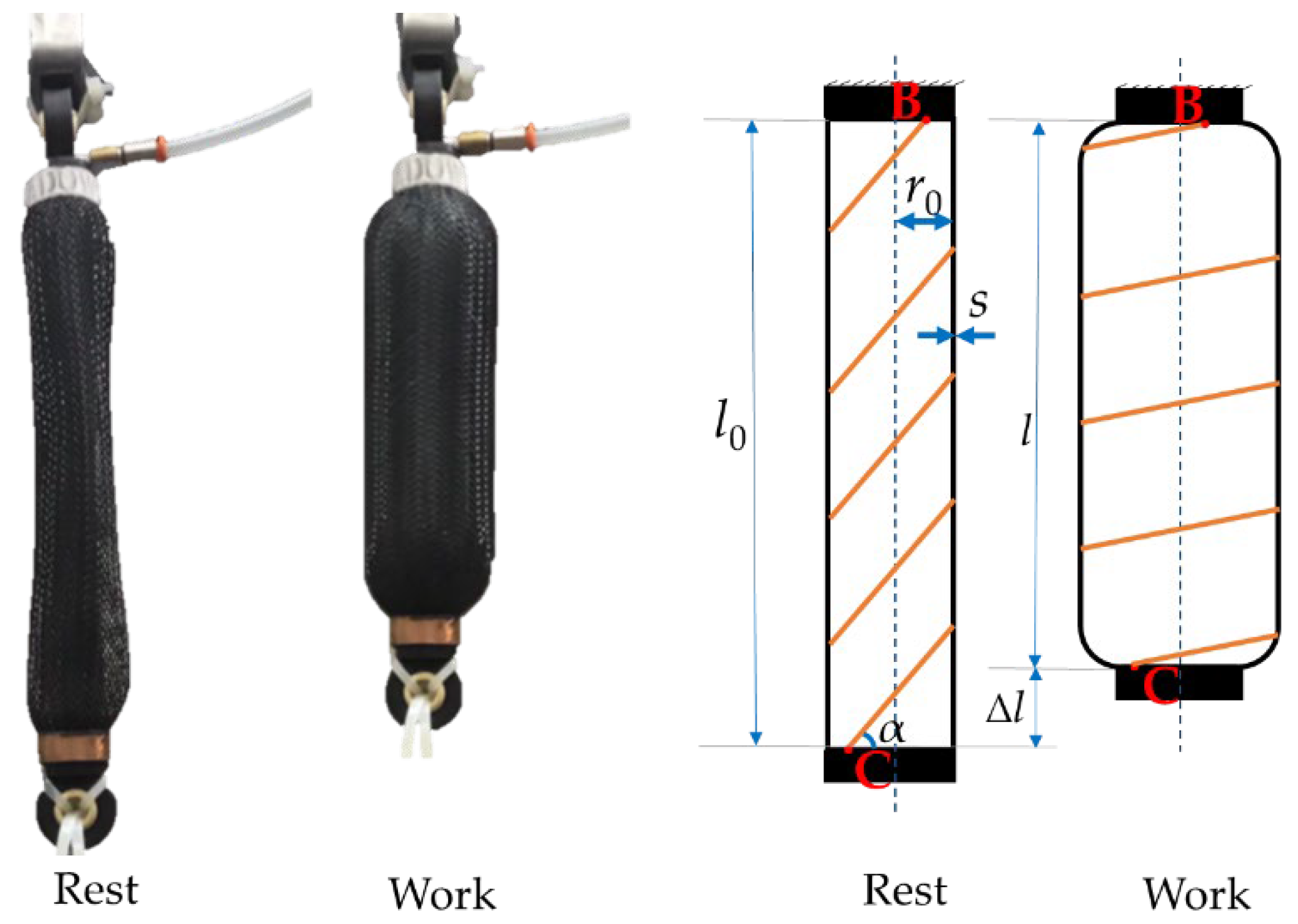
Figure 2.
Traction force of McKibben’s muscle for different geometrical and functional parameters. (a) The MKM tensile force for different supply pressure p [0.5; 1; 1.5; 2; 2.5] bar; (b) The MKM tensile force for different winding angle α of the inextensible fibers [45; 50; 55; 60; 65]°; (c) The MKM tensile force for different thickness s of the inflatable chamber [1; 2; 3; 4; 5] mm. The nominal length has been set to 0.2 m for all simulations. In the graph r0 is the resting radius; k is the contraction ratio.
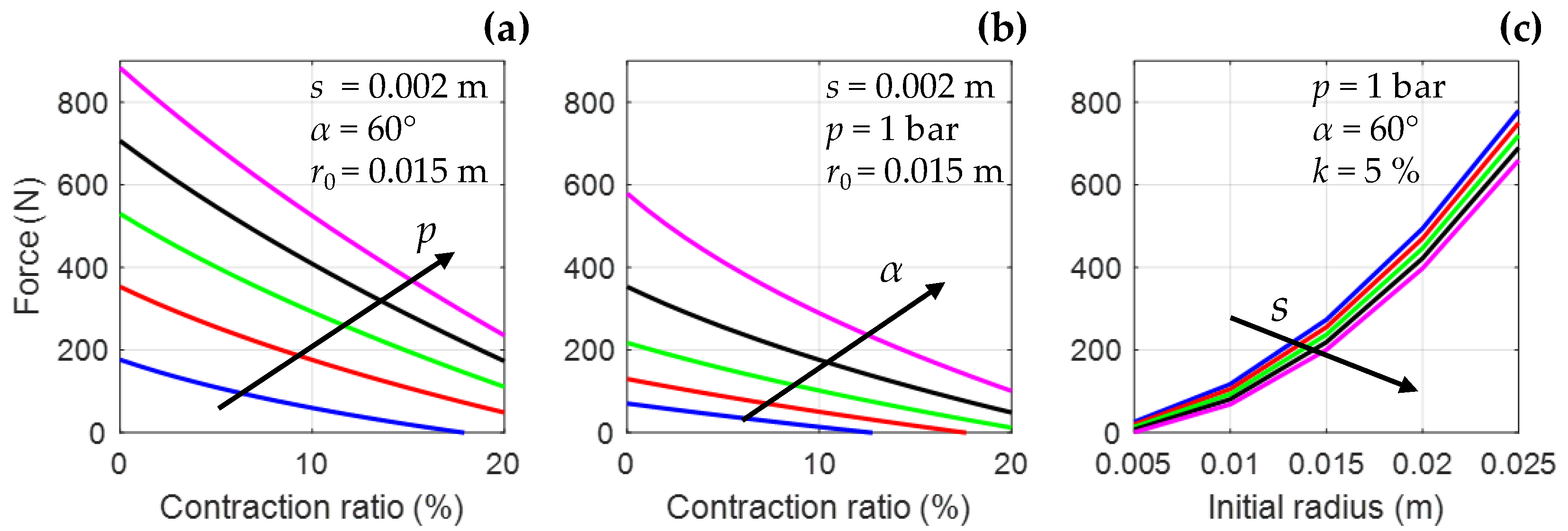
Figure 3.
Tensile force vs. contraction ratio as simulated by implementing Equation (1) [29] (dashed lines) and Equation (4) [39] (continuous lines) for different supply pressure. The analysis has been carried out for a common reference geometry: initial length 0.2, initial radius 0.015 m, chamber wall thickness 0.002 m.

Figure 4.
Straight fiber artificial muscle at resting and working condition [42]. rh, r0, l0, lf, and s are, respectively, the head radius, the initial radius, the nominal length, the fibers length, and the thickness of the inflatable chamber in resting condition; while l, R and φ are the length, the radius of curvature, and the central angle of the deformed inflatable chamber, respectively.
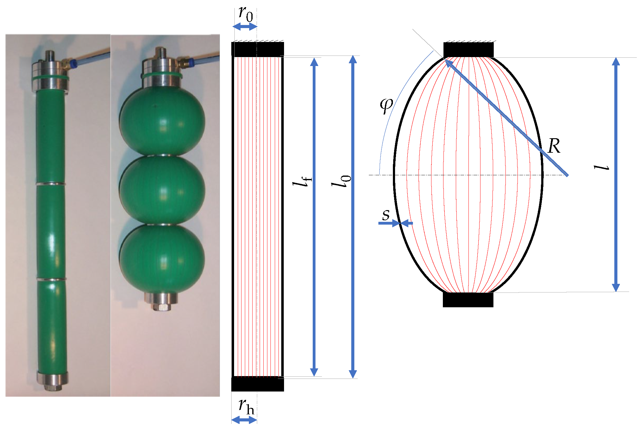
Figure 5.
Traction force of straight fiber muscle for different physical and functional parameters. (a) The SFM tensile force for different contraction ratio (k) and supply pressure p [0.5; 0.75; 1; 1.25; 1.5] bar; (b) The SFM tensile force for different initial length l0 and p; (c) The SFM tensile force for different initial radius r0 and thickness s of the inflatable chamber [1; 2; 3; 4] mm.


Figure 8.
Bending actuators prototypes with two ((a) [32,49]), and three chambers ((b) [36,50]) and their related workspaces.
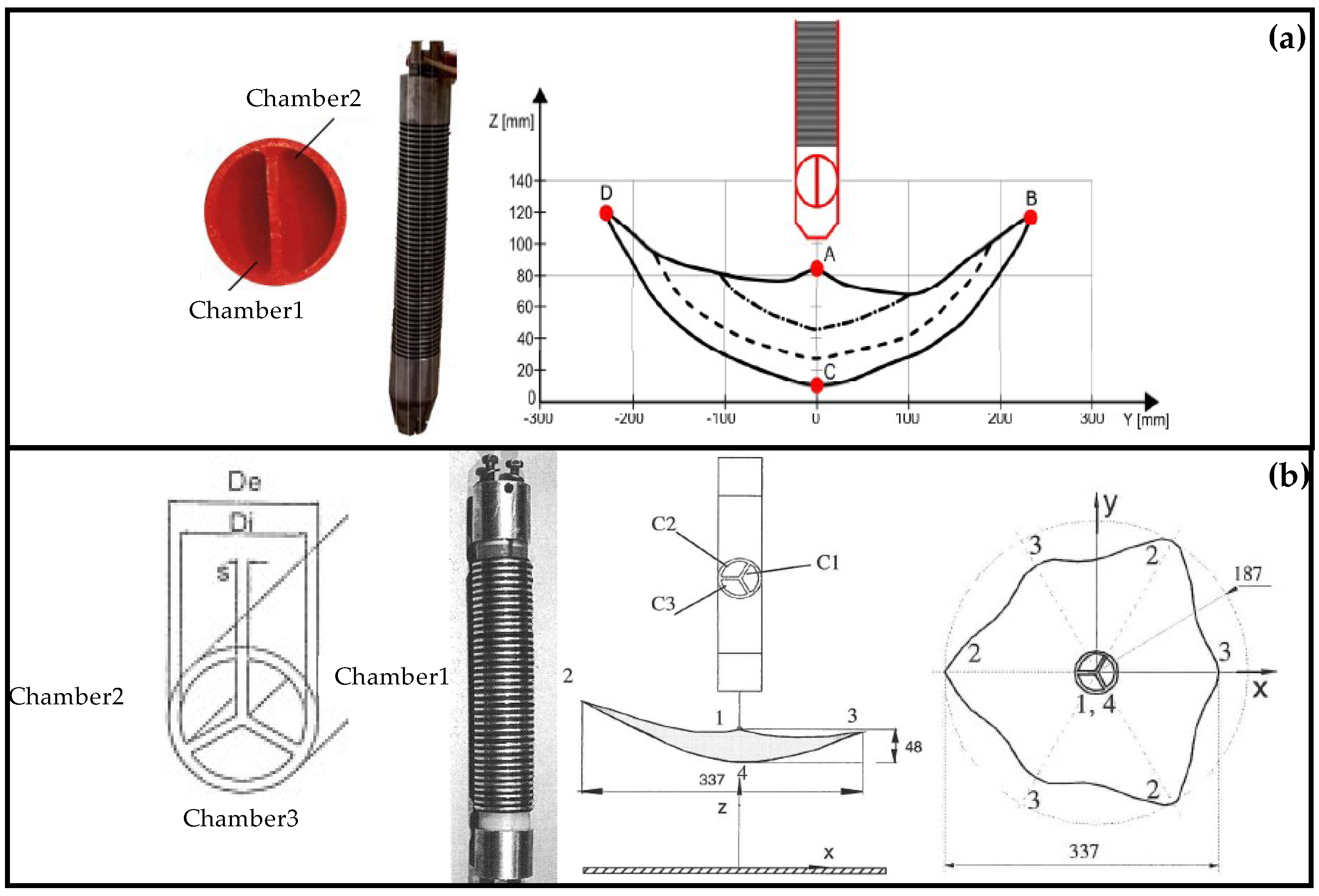

Figure 10.
Textile bellow muscle prototype: (a,b) sketches of actuator’s section; (c) picture of the actuator in pressurized condition [31,60].
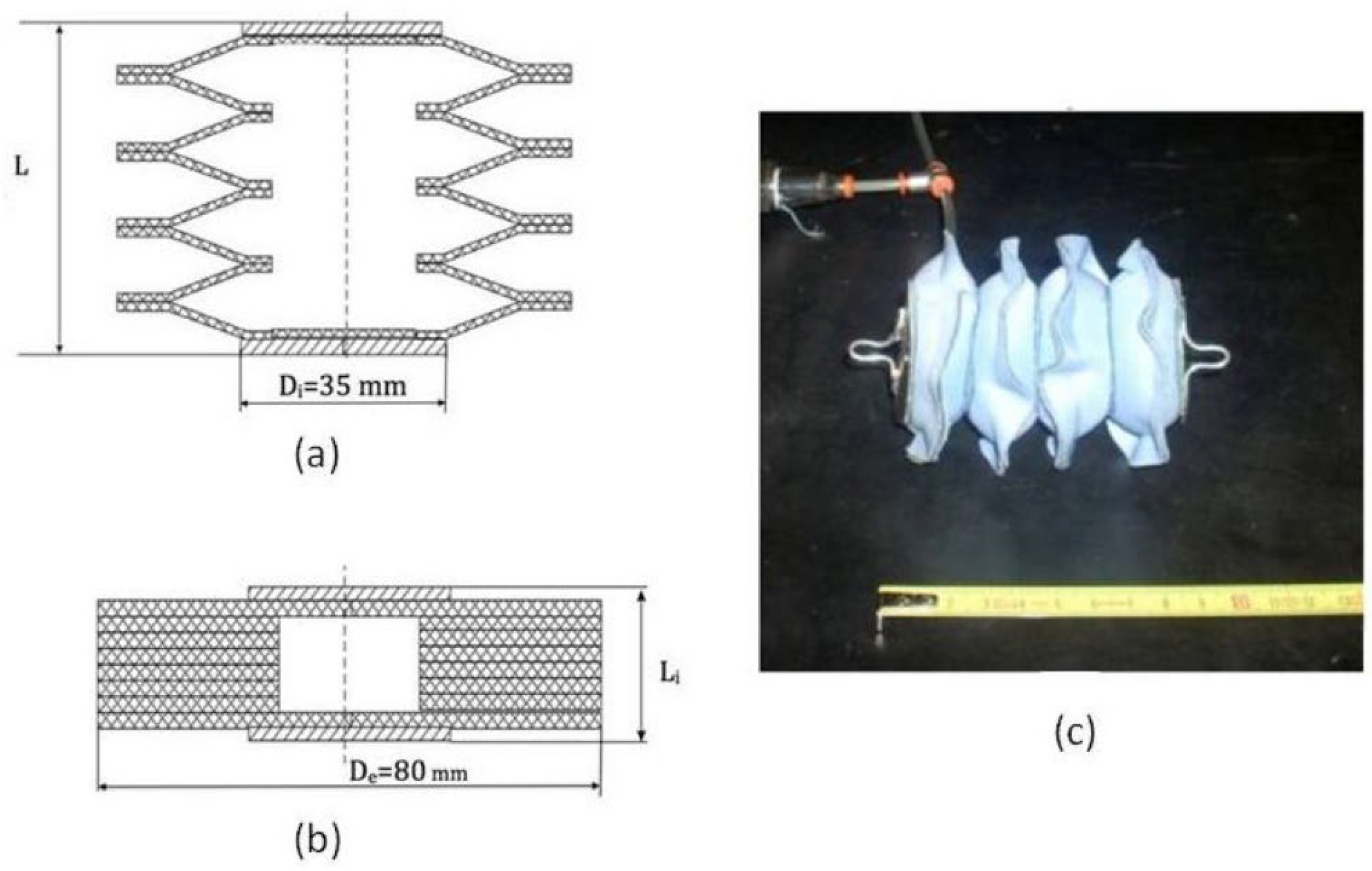
Figure 11.
Set-up to estimate vPWV [64].
Figure 11.
Set-up to estimate vPWV [64].
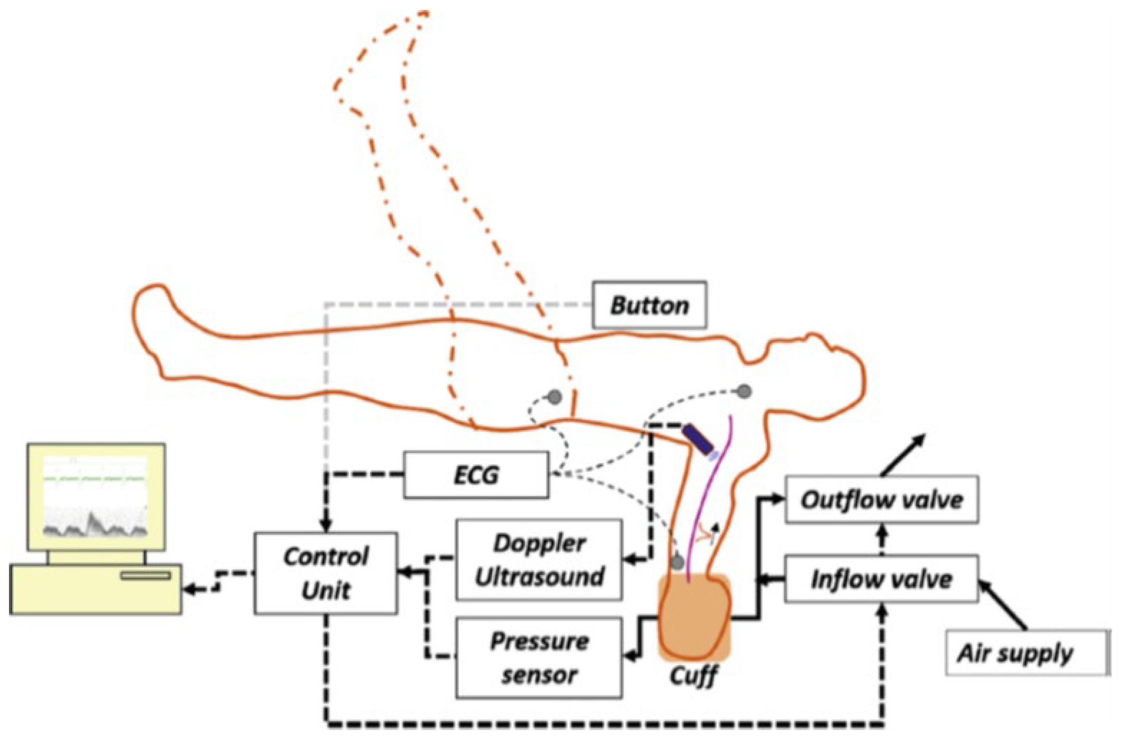
Figure 12.
A picture (a) and a sketch (b) of the six-chamber IPC device [67]. The textile air-pockets are marked with the letter a, the shells with the letter b.
Figure 12.
A picture (a) and a sketch (b) of the six-chamber IPC device [67]. The textile air-pockets are marked with the letter a, the shells with the letter b.

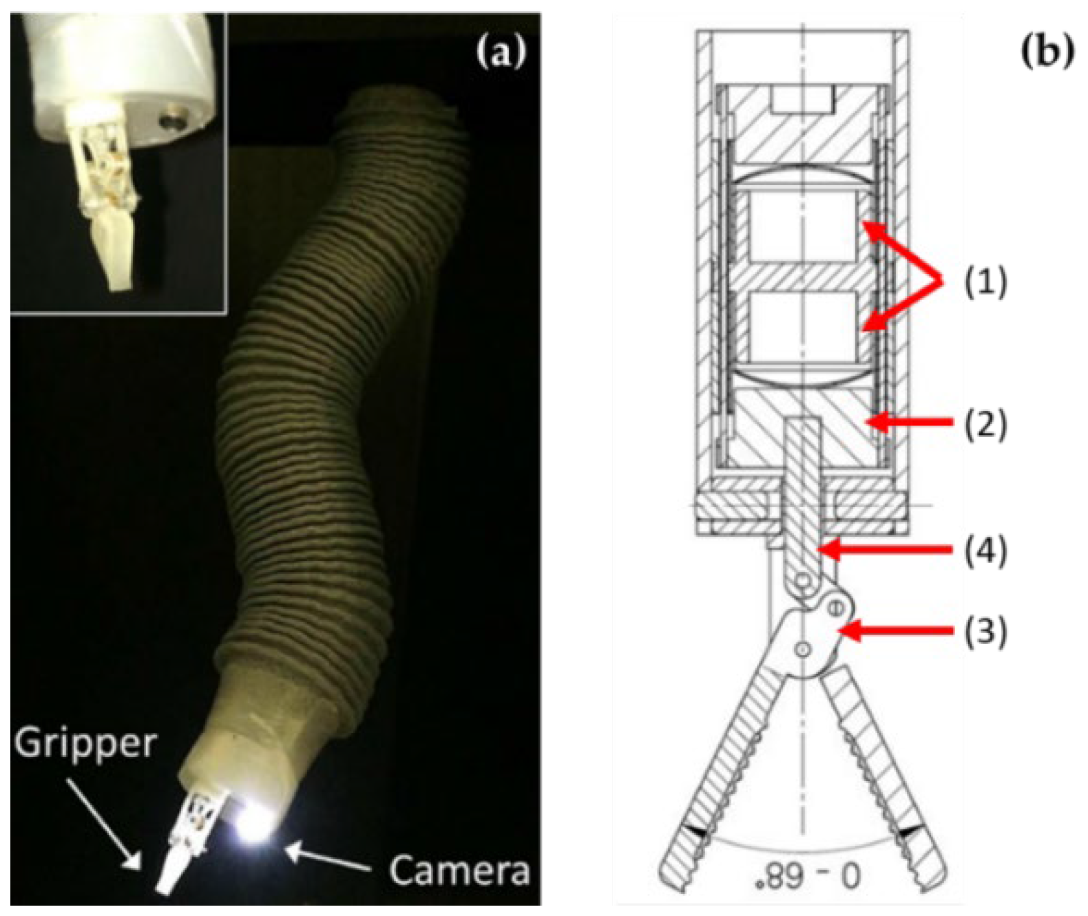
Figure 14.
A picture (a) and a sketch (b) of the haptic finger device [73].
Figure 14.
A picture (a) and a sketch (b) of the haptic finger device [73].
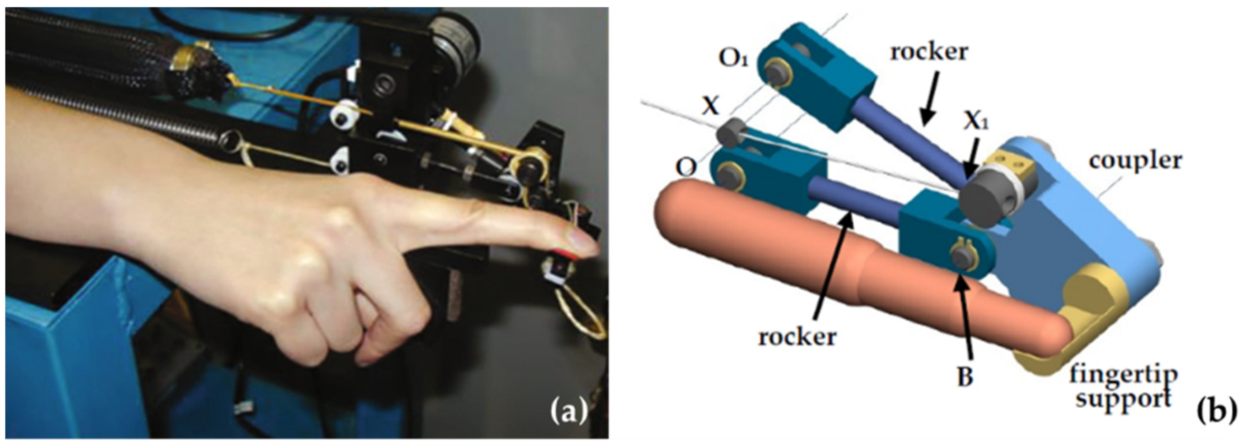
Figure 16.
Fruit-picking hand [35].
Figure 16.
Fruit-picking hand [35].
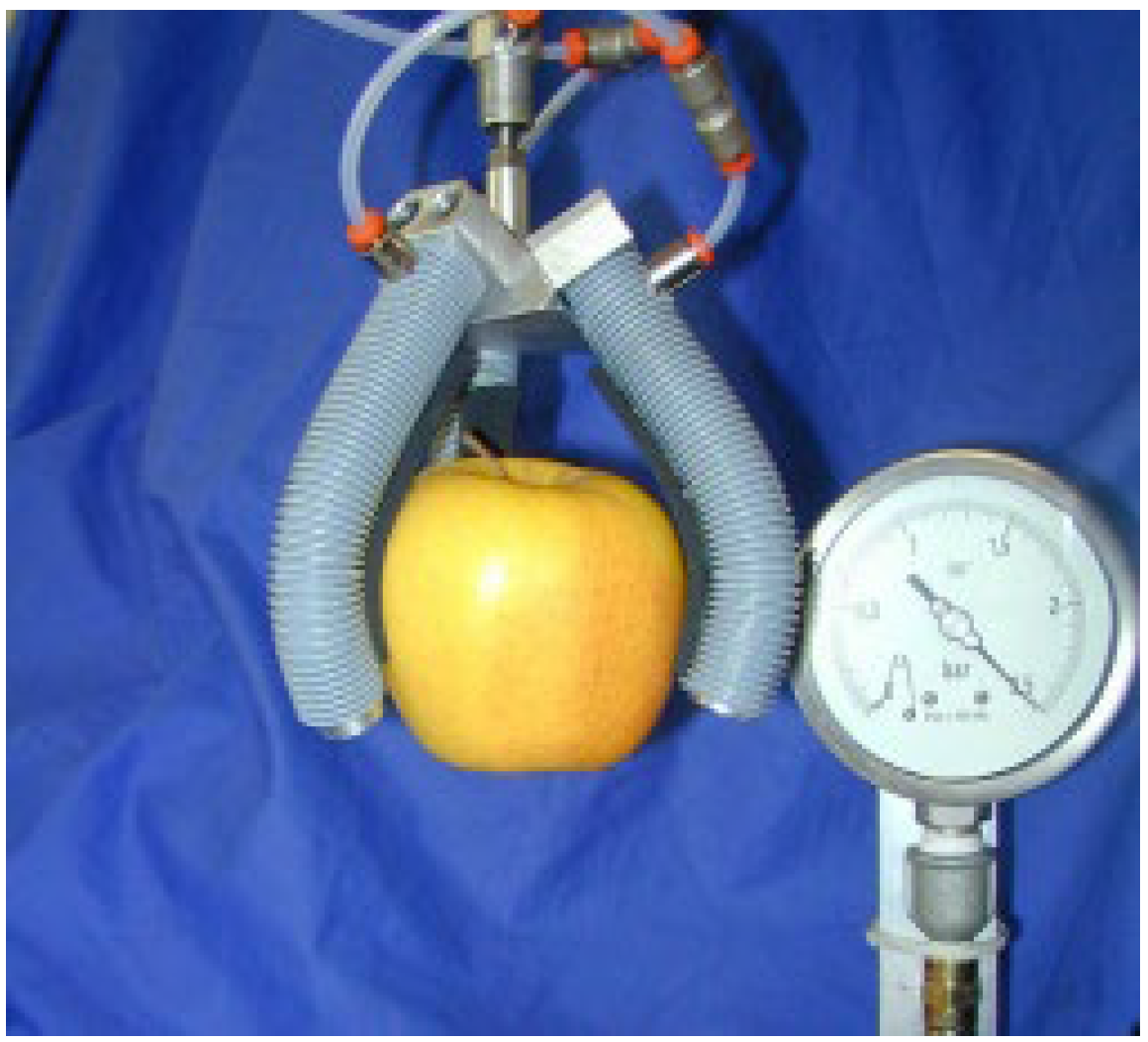
Figure 17.
Fish-robot prototype [33].
Figure 17.
Fish-robot prototype [33].
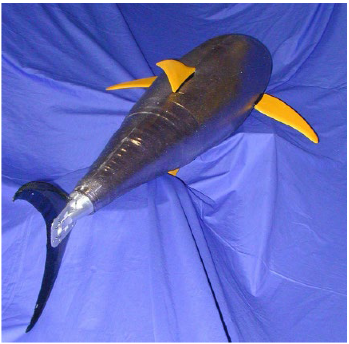
Figure 18.
(a) The frequency of publication over the years; (b) The frequency of model description. The values are expressed in percentages.
Figure 18.
(a) The frequency of publication over the years; (b) The frequency of model description. The values are expressed in percentages.
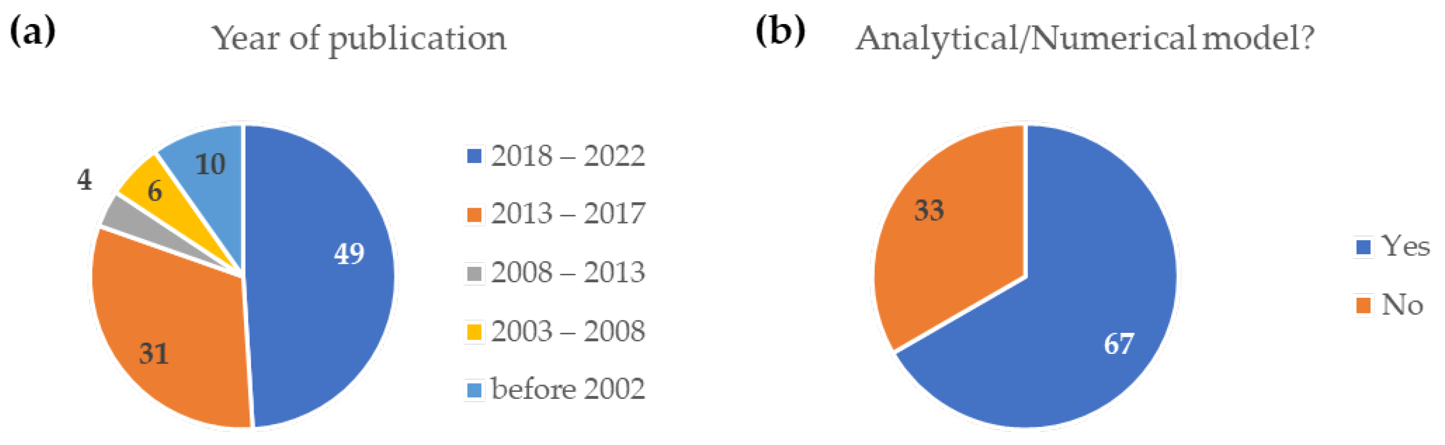
Figure 19.
Actuators type (a) and proposed applications (b). The values are expressed in percentages.
Figure 19.
Actuators type (a) and proposed applications (b). The values are expressed in percentages.

Publisher’s Note: MDPI stays neutral with regard to jurisdictional claims in published maps and institutional affiliations. |
© 2022 by the authors. Licensee MDPI, Basel, Switzerland. This article is an open access article distributed under the terms and conditions of the Creative Commons Attribution (CC BY) license (https://creativecommons.org/licenses/by/4.0/).
Share and Cite
MDPI and ACS Style
Paterna, M.; De Benedictis, C.; Ferraresi, C. The Research on Soft Pneumatic Actuators in Italy: Design Solutions and Applications. Actuators 2022, 11, 328. https://doi.org/10.3390/act11110328
AMA Style
Paterna M, De Benedictis C, Ferraresi C. The Research on Soft Pneumatic Actuators in Italy: Design Solutions and Applications. Actuators. 2022; 11(11):328. https://doi.org/10.3390/act11110328
Chicago/Turabian StylePaterna, Maria, Carlo De Benedictis, and Carlo Ferraresi. 2022. "The Research on Soft Pneumatic Actuators in Italy: Design Solutions and Applications" Actuators 11, no. 11: 328. https://doi.org/10.3390/act11110328
Note that from the first issue of 2016, this journal uses article numbers instead of page numbers. See further details here.