1. Introduction
The mobile robot is an extremely important part of the current society, and has been widely applied in exploration, disaster relief, logistics, entertainment and other scenarios. Mobile robots can be divided into three categories according to their walking modes, that is, wheeled robots [
1,
2,
3,
4], tracked robots [
5,
6] and legged robots [
7,
8,
9,
10,
11,
12,
13,
14,
15,
16,
17,
18,
19,
20,
21,
22,
23,
24,
25,
26,
27,
28,
29,
30]. Wheeled robots and tracked robots are suitable for working on flat ground. However, in daily life, mobile robots usually work in the environments with complex terrain such as gullies, steep hills and stairs. Therefore, the application of wheeled robots and tracked robots is restricted in the above-mentioned terrain. However, legged robots can imitate the movements of animals, and adapt to all kinds of uneven and steep terrain with the help of flexible coordinated motions, and further complete the work better. Therefore, the legged robot has become one of the important research focuses at present.
As shown in
Table 1, from the perspective of bionics, the traditional legged robots can fall into three categories according to their walking modes, i.e., mammalian structure [
7,
8,
9,
10,
11,
12,
13,
14,
15], reptile structure [
16,
17,
18,
19,
20,
21,
22] and arthropod structure [
23,
24,
25,
26,
27,
28,
29,
30]. Mammalian structure is the most common of them [
12], the axis of hip joint (the first joint of the leg) of these robots is parallel to longitudinal direction of the trunk, which is conducive to lateral movement of legs. The axes of other joints are perpendicular to the axis of the hip joint and parallel to transverse direction of the trunk simultaneously, which is helpful for the bending and stretching of legs. As these robots have a large workspace for legs in the vertical direction perpendicular to the ground [
11,
12], they can cross high obstacles [
12,
13,
14,
15], and further run in a leaping manner [
7,
12,
14], with a high moving speed [
7,
8,
9,
10,
11]. Therefore, mammalian legged robots are generally tall [
11,
14]. However, due to the high center of gravity, they are not stable and cannot turn flexibly, so complex sensing and control systems are needed to maintain stable motions.
On the contrary, the reptile legged robots are generally simple in structure [
16,
20,
22]. The axis of the hip joint is perpendicular to the plane of the trunk, which is helpful for the swing of legs. The axes of other joints of legs are perpendicular to the axis of the hip joint and parallel to the plane of the trunk, which is conducive to the bending and stretching of legs. As such, robots have only a small workspace for legs in the vertical direction, they have poor obstacle crossing ability and low moving speed. However, thanks to the low center of gravity [
17], the support polygon formed by foot endpoints has a large area. Thus, the said robots are of strong stability [
18,
19], can easily turn in unstructured terrain [
21,
22], and are suitable to be used as small and medium-sized household legged robots. Arthropod legged robots mostly have multiple legs, which are distributed on both sides of the body in pairs, and the bottom of the trunk is close to the ground. Compared with reptile legged robots, the said robots are characterized by lower center of gravity [
23,
26,
28,
30,
31] and better load-bearing capacity [
24,
25,
27,
29]. Nevertheless, their speed is generally slow, and their application is restricted.
Due to high flexibility, strong adaptability and good load-bearing capacity, the legged robots have attracted wide attention in recent years. However, a systematic solution has not yet been formed for the tasks in unstructured terrain and complex environment. To solve this problem, the metamorphic mechanism [
26,
32,
33] is applied to the legged robot. The “metamorphic” aspect means that institutions can reconfigure themselves according to their demands [
34]. This theory can be applied to the structural design of legged robots, for example, the conceptual walking robot which can recover from roll-over with actuated universal joints [
35], the design of a leg based on the reconfigurable Theo Jansen linkage [
36], the quadruped robot that can adapt to various terrains stably [
37,
38,
39,
40], the multi-modal ALPHRED with strong operation performance [
41], and the Scorpio with the motion ability of rolling, crawling and wall climbing [
42]. These robots can change forms according to different working conditions, thus increasing the adaptability of the environment, and the addition of reconfigurable mechanism is beneficial to enrich the function of robot. However, they did not deeply discuss the stability [
36,
37,
38,
42], workspace [
35,
38,
40,
41,
42] and reconfiguration process [
36,
39,
42] of the robot, and the problem of the robot turning over after capsizing was not effectively solved [
36,
37,
38,
40]. In this paper, the reconfigurable mechanism is applied to design a metamorphic flipping robot. The robot can transform freely between mammals, reptiles and arthropods. Therefore, it can cope with all kinds of unstructured terrain well, and turn over more quickly after capsizing. As one of the important foundations of mobile robot, the reconfigurable theory will provide a new bridge for these present questions, and a new driving force for the promotion and upgrading of mobile robots.
Furthermore, the traditional legged robots mostly adopt a rigid trunk structure, so they cannot imitate well animals which have a flexible waist. Because a flexible waist plays a key role in crawling, turning and jumping during the motion of animals [
29], the lack of a flexible waist has greatly restricted the development of legged robots. Therefore, robots with flexible waists have become the research targets of scholars. In recent years, many robots have been developed, such as centipede-inspired robots that can adapt to complex terrain [
43,
44], gecko-inspired robots with strong climbing ability [
16,
18,
20,
45,
46], modular robots that can traverse complex obstacles [
47], and milliped-inspired robots that can be used for multi-terrain exploration [
48]. These studies have confirmed that the flexible waist can help the robot to obtain better motion stability and flexibility, and adapt to more complex environments. However, the impact of the flexible waist on the robot’s workspace and stability lacks quantitative expression [
18,
43,
46,
47,
48]. In this paper, the body of the robot is designed as a flexible waist, and the influence on the stability of the robot is analyzed mathematically. Through a MATLAB simulation, the changes in workspace of foot endpoints have a more intuitive expression. The present study focuses on kinematical modeling, gait planning and reconfigurable characteristics of said robot.
2. Design of Configuration
The legged robot usually consists of legs and trunk. Legs need at least three DOF, and therefore, a 3R serial mechanism is mostly employed in the structure. The waist falls into two categories, rigid and flexible ones, according to the structure. The metamorphic flipping robot is inspired by quadrupeds in nature, and it is composed of four legs and a trunk. The structure design focuses on the legs and trunk.
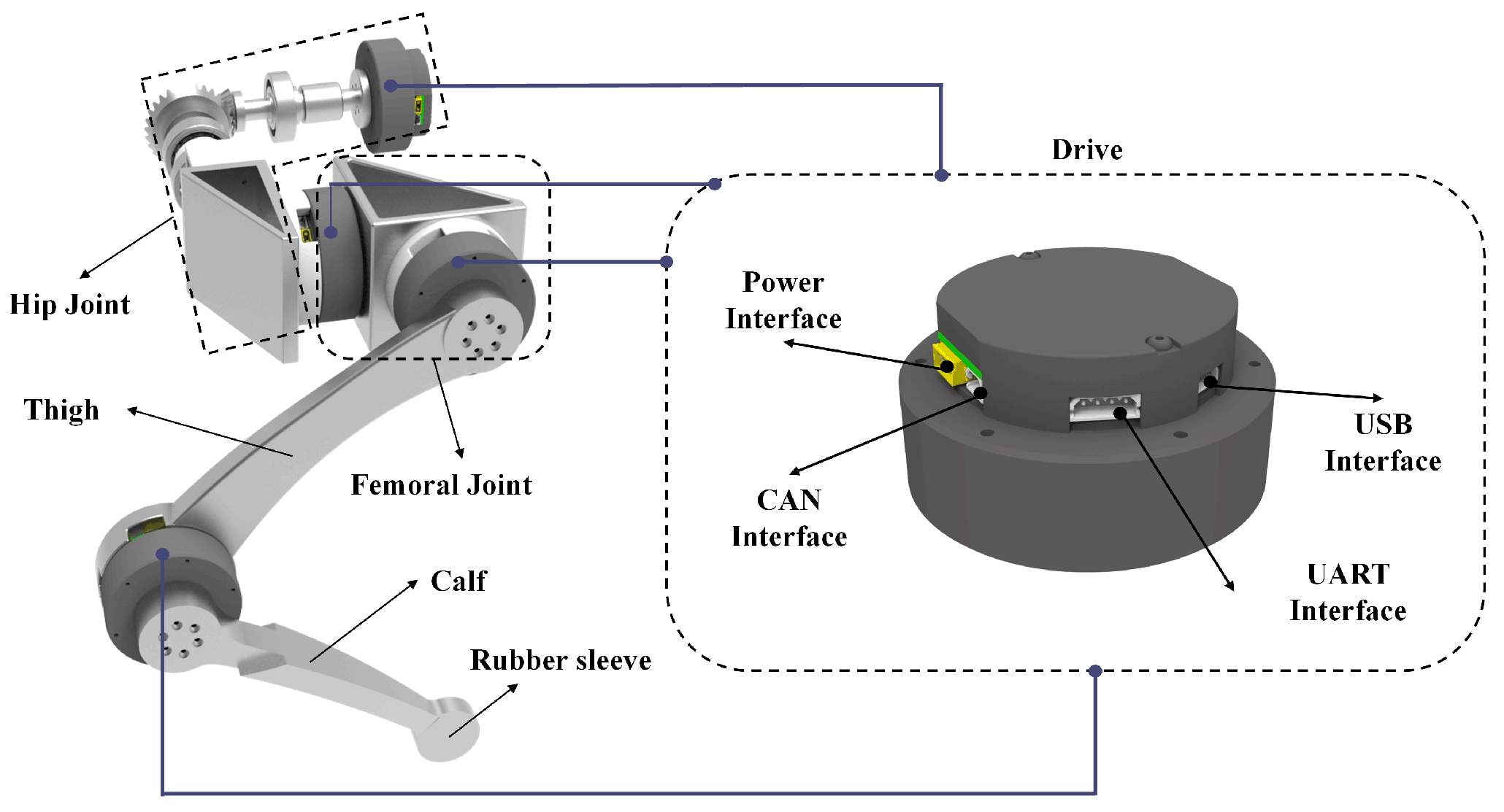
The four legs of the robot are identical in structure, and are all composed of hip joint, femoral joint, thigh, calf and four actuators, as marked in
Figure 1. The hip joint, mostly hidden in the body, is extremely important to realize the reconfigurable characteristics of the robot. The femoral joint connects the hip joint and thigh, which can coordinate the reconfiguration and motion of the robot. The thigh and calf are main moving parts of the robot, and simultaneously play the role of supporting the robot. Rubber sleeves are added to the foot position to ensure adequate friction. The moment of inertia is easily generated in the process of legs’ movement, which may cause instability of the robot and bring interference to the control. Therefore, the leg structure is designed to be lightweight while ensuring structural strength and aesthetics. At the same time, the legs have a tight lateral arrangement, with the thighs and calves close to the hip joint, where the moment of inertia of the legs is relatively low. Four actuators are power sources of the robot. Actuator 1 is located at hip joint, actuators 2 and 3 are located at femoral joint, and actuator 4 is installed at the connection position of the thigh and calf.
Actuators are core parts of the robot, which play a decisive role in motion performance of the robot. A light actuator with high controllability and comprehensive functions and its control system are developed and designed so that the actuator can adapt to all functions of the robot. The basic parameters are as shown in
Table 2.
The actuator is subject to two position control modes, namely, trajectory tracking mode and trapezoidal trajectory mode. In the trajectory tracking mode, only the target position parameters need to be specified, with no need to designate the speed and other parameters. The controller will automatically plan the corresponding speed and torque. Thus, the position and speed curves are smooth. In the trapezoidal trajectory mode, the actuator will first accelerate to the target speed with the specified acceleration, then move at the target speed for a period and decelerate to 0 with the opposite acceleration, and finally arrive at the target position. The actuator is provided with three communication control interfaces, that is, USB interface, CAN interface and UART interface, as shown in
Figure 1. In order to facilitate the control, a PC software is developed, which can connect with the actuator through USB and CAN interfaces for the control and development of the actuator.
The trunk of the robot is divided into three parts, including the front, the waist and the back. As shown in
Figure 2, both the front and the back are made by two connected boxes which are almost identical in structure. The internal structure of the box matches the hip joint structure of the robot, and there is enough space for storing batteries. Most parts of the robot are made of aluminum alloy, which has high strength and a low mass, and the total mass is 11.89 kg. Considering the influence of the moment of inertia generated during the robot motion on the stability, the mass of the robot is mainly concentrated in the trunk. This design makes the projection of the center of gravity concentrate on the interior of the robot’s supporting triangle during different motions to maintain stability. A hinge structure is arranged at the waist of the robot, so that the robot can have a flexible waist. To ensure overall beauty of the robot and protect internal electronic components and circuits, the overall waist structure is wrapped in an organ cover which can connect the front and the back. Take the mammalian form as an example, the key parameters of robot are shown in
Table 3.
3. Analysis of Motion Ability
Many animals in nature have a characteristic that cannot be ignored during their motions; that is, their trunks do not keep straight all the time, but twist constantly with the motions of their limbs. In relevant studies on legged robots, quite a few scholars have discovered the changes to robot motion by implementing a flexible waist. Park [
49] found that the flexible waist played a crucial role in the turning motion of the robot, and this structure could greatly improve the turning ability of the robot. Khoramshahi [
50] found that the flexible waist could improve the robot’s moving speed, thus improving its motion efficiency. Pouya [
51] found that the flexible waist could improve the motion stability of the robot, thereby reducing the sliding phenomenon of the robot.
To sum up, it can be stated that compared with a rigid trunk, the flexible waist endows the robot with some new advantages. In this paper, a reconfigurable robot with a flexible waist was proposed, which could change its motion characteristics by twisting the waist. In this section, the influence of flexible waist on the workspace of the robot’s trunk and foot endpoints and stability margin will be analyzed.
3.1. Influence on Trunk Workspace
Trunk workspace refers to the set of spaces that the robot’s center of mass can reach without sliding [
52], which is an important feature affecting the motion stability of the robot. Compared with the robot with a rigid trunk, the flexible waist enables the robot’s center of mass to move in a larger space by twisting. Its function will be specifically analyzed by virtue of the model.
As shown in
Figure 3, the robot can twist its trunk to make its center of mass change from the original point
O to point
C. For the convenience of analysis, the trunk of the robot is regarded as a movable platform, and the four legs are treated as four chains, which together form a parallel mechanism [
53]. A trunk workspace can be calculated based on each single chain. Therefore, the intersection of four workspaces calculated based on four chains is the final trunk workspace of the robot. In this model, the four chains are identical, so only the workspace of a single chain needs to be calculated.
Next, the chain formed by leg 4 is taken as an example for analysis. As shown in
Figure 3, the robot body coordinate system
O-xyz is established with the robot’s original center-of-mass point
O as the origin. The robot’s center-of-mass point
C is connected with the center point
S4 of the femoral joint to obtain the vector
CS4, and
S4 is connected with the foot endpoint
F4 to acquire
S4F4. Subsequently, point
C4 is taken along the direction of vector
S4F4 through point
C to make the vectors
CC4 and
S4F4 equal in size. Connect
F4C4 to obtain a parallelogram
CS4F4C4. Based on the vector operation rules, the following formulae can be obtained.
where
,
C and
are vectors from the origin
O to the center point
of the femoral joint, the center-of-mass point
C and the foot endpoint
, respectively. Therefore, Formulas (1) and (2) can be rewritten as
where
represents the distance from the foot endpoint
to the center point
of the femoral joint, which is represented by
d.
As the center point
of the femoral joint is the position where chain
i connects with the movable platform, it will always be in the workspace of chain
i. The foot endpoint
is a fixed point. When leg
i is in the maximum stretching state, the trajectory of
will form a spherical surface centering on
, with the spherical radius expressed by
dmax. When leg
i is in the maximum folding state, the trajectory of
will also form a spherical surface centering on
, with the spherical radius expressed by
dmin. The two spherical surfaces constitute the inner and outer boundaries of
, and the folding and stretching of legs correspond to the movement of
in the inner and outer boundaries. Therefore, the motion range of
can be regarded as the whole space between two spherical surfaces. Since the quadrilateral
CH4F4C4 is a parallelogram, the formula below is obtained.
where
represents the vector from point
O to point
(
i = 1,2,3,4).
Assume that
= [
], Formula (3) can be rewritten as
According to Formula (5), it can be concluded that the center-of-mass point C can be regarded as a set of points centering on with a distance of d. When d = dmax, the center-of-mass point C is the farthest from , and its trajectory forms a spherical surface. When d = dmin, the center-of-mass point C is the closest to , and its trajectory also forms a spherical surface. The space between the two spherical surfaces constitutes the active area of the center of mass. Therefore, the final trunk workspace is the intersection of active areas centering on and corresponding to the four chains.
When the robot twists its trunk, its center of mass will move accordingly, so will , which will lead to the movement of active areas corresponding to the four chains, and finally result in the movement of the intersection of four active areas. As such, the space area swept by the intersection of active areas will be expanded. To sum up, the robot with a flexible waist will be provided with a larger trunk workspace, which means that the robot has a larger adjustment margin when walking, and can adjust its motion performance in a wider range.
3.2. Influence on Workspace of Foot Endpoints
The workspace of foot endpoints refers to the set of space areas that the foot endpoints of the robot can reach, which is of great significance for the study on gait planning and obstacle crossing planning of the robot. For the robot with a rigid trunk, the legs are generally regarded as a 3R serial mechanism in research to further study the workspace of this mechanism. However, for the robot with a flexible waist, the twisting of the waist enables the foot endpoints of the robot to arrive at a larger space area. In order to deeply study the influence of the flexible waist on foot workspace, simulation will be conducted by MATLAB next. Considering that the four legs of the robot are the same in structure, the simulation is needed only for one leg. To make the comparison better, simulation tests were carried out for the robots with a rigid trunk and a flexible waist, respectively. Except for waist parameters, other joint parameters of the two robots are identical. The torsion parameters of each joint are as shown in
Table 4.
The test results are as shown in
Figure 4. By comparing the projections of workspace in
x-
y directions, it can be found that the range of the robot with a rigid trunk is (5 cm, 22 cm) on
X-axis and (−45 cm, −10 cm) on
Y-axis, while the range of the robot with a flexible waist is (−1 cm, 22 cm) on
X-axis and (−55 cm, −10 cm) on
Y-axis. Obviously, the robot with a flexible waist has a larger workspace, which proves that the flexible waist can improve the foot workspace. With a larger foot workspace, the robot can implement more moving postures, and greatly improve its obstacle crossing ability and stability at the same time.
3.3. Influence on Static Stability Margin
As mentioned above, when the robot twists its trunk, its center of mass will move accordingly, which will impose a great impact on static stability margin (SSM) of the robot, and further affect motion ability and anti-interference ability of the robot. In this section, the influence of the flexible waist on SSM will be analyzed.
SSM of the robot refers to the shortest distance from the projection of the robot’s center of mass on the ground to the boundary of its support polygon [
54,
55]. Only when the projection falls inside the support polygon can the robot remain static stability. However, for SSM, it is required to calculate and compare the distances between the projection point and several straight lines, which is complicated in the practical application. To simplify the calculation process, longitudinal stability margin (LSM) was adopted. LSM refers to the distance between the projection of the robot’s center of mass on the ground and the boundary of its support polygon in longitudinal direction of the robot, which is a simpler calculation method of SSM. Longitudinal direction of the robot generally refers to the forward motion direction.
As shown in
Figure 5, point
O is the projection point of the robot’s center of mass on the ground. A straight line is drawn through point
O along the longitudinal direction to intersect with the support polygon, and the line segment formed is LSM. In order to measure the LSM of quadrupeds, a periodic static gait with a series of leg lifts was selected. Taking the proposed robot as an example, the sequence is Leg 4, Leg 2, Leg 3 and Leg 1, which is called the standard cyclic gait of quadruped robots. Further, it is assumed that the robot walks in a straight line on the flat ground at a constant moving speed, with the distance between the center of gravity and the ground remaining unchanged. With the front of the robot trunk as a reference, if the waist rotates counterclockwise, the torsion angle will be positive, while otherwise, it will be negative. The robot gait is shown in
Figure 6:
As shown in
Figure 7, when the robot moves forward in a periodic gait, both the support polygon and the center-of-mass are in a transition state.
(
i = 1, 2, 3, 4) is the foot endpoint of leg
i. ∆
is the support triangle when leg 4 moves, and ∆
is the support triangle when leg 2 moves.
H is the intersection point of straight lines
and
. For the traditional robot with a rigid trunk, its center-of-mass is always located at the point
O. However, for the robot with a flexible waist, its center of mass will move to point
C after twisting.
As shown in
Figure 7, in the coordinate system
-
, the coordinates of points
,
,
and
can be expressed as
(0,
b),
(
a,
b − (
s/2)),
(0, 0) and
(−
a, (
s/2) −
b), respectively. Then, vectors
= [−
a b – (
s/2)]
T and
= [−
a (
s/2) −
b]
T. As ∠
H is always an acute angle,
The x-coordinate of
H in
O-xyz can be expressed as
At this time, the longitudinal stability margin of the robot can be expressed as
where
φ = ∠
F1 HF3/2.
Let
η =
/
, and Formula (9) can be rewritten as
where
(
i = 1, 2, 3, 4) represents the mass of four legs of the robot.
refers to half the length of the robot trunk, and
represents the width of the robot trunk.
φ is related to the distribution of foot endpoints of the robot, but has nothing to do with the torsion angle
θ.
For robots with a rigid trunk, they cannot move horizontally like the center of mass of the robots with a flexible waist. Therefore, their longitudinal stability margin can be expressed as
Therefore, the increment of longitudinal stability margin of the robot with a flexible waist relative to the robot with a rigid trunk can be expressed as
By dividing
by
, a dimensionless element can be obtained, which is expressed as
The dimensionless element τ is called stability improvement factor, which can be used to evaluate the improvement of robot stability margin due to the flexible waist. In addition, the stability improvement factor can also be used to guide the gait optimization of robots with a flexible waist, so as to obtain a better stability margin. It can be seen from Formula (12) that with a larger torsion angle of the robot waist, the increment of longitudinal stability margin will also increase monotonically.
4. Motion Planning
4.1. Reconfigurable Motion
A kind of reconfigurable robot was proposed in this paper. The said robot can be freely reconfigured among mammal, reptile and arthropod forms, and has the advantages that common robots with a single form do not have. In this section, the reconfiguration process of the robot will be expounded.
As the four legs of the robot are distinguished by front and rear boxes, and are in pairs, it is only necessary to analyze the reconfiguration process of one foreleg and one hind leg. As shown in
Figure 8, the left foreleg is taken as an example. When the robot needs to be reconfigured from mammal form to reptile form, it will perform the following motions successively. First of all, actuator 4 will drive the calf to move closer to the thigh, so as to reduce the motion moment in the subsequent motion process. Then, actuator 2 will drive the whole leg to turn over by 180°, so that the femoral joint can move to the designated position. Finally, driven by actuators 3 and 4, the thigh and calf will move until the calf finally touches the ground to complete the motions. The motion sequence of the right foreleg is exactly the same as that of the left foreleg.
As shown in
Figure 9, the left hind leg is taken as an example. First of all, actuator 4 will drive the calf to approach the thigh. Then, actuator 3 will drive the thigh and calf to move together to the designated position. Finally, actuator 4 will drive the calf to touch the ground to complete the motions. The motion sequence of right hind leg is exactly the same as that of the left hind leg. The four legs will move in succession according to the order of left foreleg, right foreleg, left hind leg and right hind leg. In the motion process of each leg, other three legs will keep supporting the robot, so as to ensure the stability of its body and motions.
Through the above-mentioned simple motions, the robot can complete the reconfiguration from mammal form to reptile form. As mentioned in the introduction, the robot is suitable for scenarios that require fast movement in the mammal form, such as carrying small goods over long distances. When the robot is in reptile form, it is suitable for performing tasks in complex environments, such as field expeditions.
If the robot is required to further lower its center of gravity in the working environment and fold its legs to reduce the occupied space, the robot can be reconfigured from reptile form to arthropod form. As shown in
Figure 10, actuator 1 will drive the femoral joint of the robot to gradually move to the designated position, while the other three actuators will drive the legs to cooperate with the motion of the femoral joint, finally completing the motions. In this process, the motions of four legs can be carried out simultaneously without affecting the overall stability of the robot. When the robot is in the form of arthropod, it is suitable for handling large goods at close range, or replacing human work in some dangerous environments, such as rescue and disaster relief.
Of course, the robot can also be directly reconfigured from mammal form to arthropod form by completing continuous motions. The specific motions are the same as the above transformation process, and they will not be repeated here. With the help of free reconfiguration among the three forms, the robot can greatly improve its adaptability, adapt to more environments and accomplish more work. For example, when the robot encounters a tall obstacle in the reptile form, it can transform to the mammal form instead of turning around.
4.2. Motion of Turning over after Capsizing
For animals in nature, turning over quickly after capsizing is one of the key survival skills to avoid predators. A great number of animals such as dogs, cats and tigers have good ability of turning over after capsizing. However, the existing robot structure cannot be as flexible as that of animals, which has greatly restricted the application of robots, and how to turn over after capsizing becomes a new problem. In attempt to provide robots with the ability of turning over after capsizing, numerous scholars have carried out relevant research. Li et al. [
55], inspired by cockroach, proposed a kind of robot that could turn over by wings. PENG et al. [
56] designed an insect-like hexapod robot which could turn over after capsizing by imitating the motion of turning over of insects in nature and through the coordinated motions of six legs. Wang et al. [
57] propose a four-step backflip strategy by kinematics and energy analysis; they verify that reconfiguration makes it easier for the robot to turn over after capsizing.
As a whole, the robots may capsize in two forms; that is, the body capsizes sideways and along the forward motion direction. The existing solutions to a robot turning over after capsizing mostly rely on closed-loop control, dynamic adjustment or additional parts, which cannot adapt to the complicated and changeable situations in practical application. Therefore, these solutions may not have a good effect.
In the three forms of robots, the robots in reptile and arthropod forms have lower center of gravity, larger support area and more stable body. Thus, capsizing mostly occurs in mammal form. Additionally, it should be noted that mammalian robots can be divided into four types according to leg structure, i.e., total-knee type, full-elbow type, front-knee and back-elbow type, front-elbow and back-knee type, and the robot can complete normal work in all these types. Based on this, with mammal form of the robots as an example, a novel strategy of turning over after capsizing was put forward by virtue of reconfigurable characteristics of the robot in this paper.
As shown in
Figure 11, if the reconfigurable quadruped robot capsizes sideways, it will turn over by the following motions. Firstly, the calf, driven by actuator 4, will move closer to the thigh, so as to reduce the moment required for leg rotation. Then, actuator 3 will drive the thigh and calf to approach the ground until the calf touches the ground. Finally, actuators 3 and 4 will work together to drive the thigh and calf to slowly support the whole robot. The robot will change from total-knee type to full-elbow type, and can return to normal work.
If the reconfigurable robot capsizes due to flip, the restoration process is similar to sideways capsizing. Finally, the robot will also change from total-knee type to full-elbow type, and can return to normal work. The turning over process is as shown in
Figure 12.
Under the conditions of the same size and the same requirements for turning over, in the proposed solution, the robot only needs to overcome its own gravity to complete the motion of turning over. However, in traditional solutions, the robots mostly turn over by inertia and rely on actuators to provide instantaneous huge force. The proposed solution to a robot turning over makes the best of the unique structural advantages of the reconfigurable quadruped robot. As such, the robot can not only turn over quickly, but also keep its center of gravity in the support polygon all the time. Therefore, the robot can transform stably and adapt to various complex working scenarios. Meanwhile, the proposed solution also reduces the requirements of robots for actuators, and improves the efficiency of turning over.
5. Simulation Based on ADAMS
To test the proposed gait planning and reconfiguration process, a model is developed for the metamorphic flipping robot and a simulation is carried out based on ADAMS. In order to simulate the real environment, robot is given real material properties, and all 17 degrees of freedom of the robot are constrained. According to the standard cyclic gait designed in
Section 3.3, the driving function is designed for control, and a flat plate model is established as the ground, and parameters such as contact force and friction force are added between the position of the foot endpoints and the ground. In order to verify the influence of the twisted waist on the robot motion, this paper also simulates the rigid trunk robot. For comparison, the drive of other joints is unchanged except that the drive of the waist is set to 0. The simulation videos of motion process are showed in the
Supplementary Materials.
Figure 13 shows the motion process obtained by ADAMS simulation. The simulation process well demonstrates the robot’s superior motion performance. Under the given drive, the robot moves on the ground according to the planned gait, and achieves stable progress, which indicates that the structural design of the robot is reasonable.
Figure 13 also shows the displacement–time curves of the two kinds of robots. It can be clearly seen that in the case where only the waist is different, the robot with a flexible waist has a larger displacement than the rigid trunk robot in a standard cyclic gait, specifically, about 0.04 m more. This suggests that the flexible waist contributes to the growth of the robot’s movement speed. Furthermore, the slope of the curve in the forward process of the flexible waist robot changes, which means that the speed of the robot changes. Especially when the waist returns to a straight state, the speed of the robot is greater, which is the key to widen the gap between the flexible waist robot and the rigid trunk robot.
In addition, the reconfiguration and turning process of the robot is also demonstrated in ADAMS.
Figure 14 shows the simulated motion process. Driven by the plan, the robot transforms from the initial mammal state to the reptile state and finally to the arthropod state according to the action designed in
Section 4. The same effect is also reflected in the turning action. The simulation process shows that the structure of the robot is capable of reconfiguring and turning over. In order to explore whether the actuators can make the robot work properly, the torque of the robot joints is also obtained in the simulation. Represented by the turning action with large joint force,
Figure 14 shows the change in the torque of the actuator 3 and 4 with time during the turning process. It can be seen that the maximum torque appears around 1.5 Nm and 0.45 Nm, respectively, which is smaller than the actuator’s rated torque, so the robot can complete the action normally.
In order to explore the improvement of the robot’s environmental adaptability brought by reconfigurable performance, two scenarios are designed in this paper and simulated in ADAMS. As shown in
Figure 15, when there is a low table in front of the robot, the mammal robot cannot pass. The traditional approach is to go around or jump, but both are highly influenced by the environment. However, if the robot is reconfigured as arthropod, it can pass through easily, and the simulation shows this process. When the robot is used in the field, it will inevitably encounter steep slope, especially when the slope is large, the movement will be more challenging. When the robot is in the mammal form, the center of gravity is high, the support area is small, the impact of movement is large, which makes the body very unstable, and the body will often tilt or even slide down. When the robot changes to the arthropod form, the motion stability is significantly improved. The simulation shows the process of the robot climbing the slope.
However, the simulation process also exposes some unconsidered problems. When the joints of the robot are moving, the rotational inertia will cause instability of the robot’s body, which will bring trouble to the control of the robot. In severe cases, it may even cause the robot to capsize. Therefore, in the subsequent process of making the prototype, the mass distribution and rotational inertia balance of the robot should be deeply considered, and the properties of the materials should be reasonably configured to make the robot’s structure more reliable.
6. Summary
In recent years, the legged robot has been widely concerned by scholars all over the world and has become a research focus in the field of robots because of high flexibility, strong adaptability, good load-bearing capacity and other advantages. In this paper, a kind of reconfigurable legged robot is proposed, with the characteristics as follows:
The proposed robot has outstanding reconfigurable characteristics and can transform freely among three forms. With an innovative flexible waist, the robot can twist its trunk flexibly, thus changing its motion performance.
By establishing a mathematical model of the robot, it is proved that the flexible waist can increase the trunk workspace and static stability margin of the robot. Additionally, MATLAB is employed for simulation, and the conclusion is drawn that the flexible waist can increase the workspace of foot endpoints.
By imitating the quadrupeds in nature, the gait planning of the robot is provided. In addition, the motion plan of robot posture reconfiguration is introduced by analyzing reconfigurable characteristics of the robot. Aiming at capsizing, a solution to a robot turning over, achieved by posture reconfiguration, is put forward.
To test the robot’s gait planning, reconfigurable characteristics and whether the actuator is capable of working, the model of the robot is established and simulated by ADAMS. The simulation results show that the robot can complete various actions well with the cooperation of the designed driver and accomplish tasks that traditional robots cannot, which further verifies the rationality of structural design and motion planning.
In order to further improve the performance and practicability of robots in the future research, the robot will be planned and improved from the perspective of the control system, lightweight structure and artificial intelligence. In the future, the metamorphic flipping robot can give full play to its own advantages and make greater contributions to humans in complex environment detection, transportation of goods, education, entertainment, etc.


 ,
, 


 Leopard


 Chameleon


 Spider

