Article

Vibration Isolation Performance of an Adaptive Magnetorheological Elastomer-Based Dynamic Vibration Absorber

Department of Aerospace Engineering, University of Maryland, College Park, MD 20742, USA
*
Author to whom correspondence should be addressed.
Actuators 2022, 11(6), 157; https://doi.org/10.3390/act11060157
Submission received: 15 April 2022 / Revised: 20 May 2022 / Accepted: 23 May 2022 / Published: 12 June 2022
(This article belongs to the Special Issue Active, Semi-active and Passive Vibration Control)

Abstract

:
This study evaluates the vibration isolation performance of an adaptive magnetorheological elastomer (MRE)-based dynamic vibration absorber (MRE-DVA) for mitigating the high frequency vibrations (100–250 Hz) of target devices. A simple and effective MRE-DVA design was presented and its vibration isolation performance was experimentally measured. A cylindrical shaped MRE pad was configured to be operated in shear mode and also worked as a semi-actively tunable spring for achieving adaptive DVA. A complex stiffness analysis for the damper force cycle was conducted and it was experimentally observed that the controllable dynamic stiffness range of the MRE-DVA was greater than two over the tested frequency range. The transmissibility of a target system was measured and used as a performance index to evaluate its vibration isolation performance. It was also experimentally demonstrated that a better vibration isolation performance of the target device exposed to the high frequency vibrations could be achieved by using the adaptive MRE-DVA.

1. Introduction

Since structures and systems are inevitably exposed to undesirable vibrations, vibration isolation technology has been an important research topic for several decades to protect them. One effective way of achieving vibration isolation is to use dynamic vibration absorbers (DVAs) because of their simplicity and low cost [1,2]. Typically, DVAs consist of a stiffness, a damping, and an oscillating mass, but can effectively reduce the forced vibration of host structures and systems excited by external harmonic excitations with a specific frequency [3,4,5]. However, passive DVAs typically have a narrow working frequency bandwidth only focused at their resonant frequency. Thus, they lack adaptability to changes in the excitation harmonic frequency [6,7]. As a result, even a slight mistuning of passive DVAs can result in poor vibration isolation performance. To broaden the working frequency bandwidth, adaptive DVAs that can adjust their resonant frequency via external control inputs have been recently developed in order to cope with shifting harmonic excitation. Several studies using electromagnets [8,9], piezoelectric materials [10,11], shape memory allosy [12,13], and magnetorheological elastomer (MRE) [14,15,16,17,18,19,20,21,22,23,24,25,26,27,28,29,30,31,32,33] have been reported to implement adaptive DVAs.
Among these adaptive DVAs, this study focused on the MRE-based adaptive DVA, or MRE-DVA because it can provide a continuously controllable stiffness and damping. Such an adaptability of the MRE-DVA is attributed with MREs, which are smart particle reinforced composites [34,35]. MREs can significantly change their physical or mechanical properties by adjusting an external magnetic field, similar to magnetorheological fluids (MRFs). However, unlike MRFs [36,37,38,39,40], MREs are immune to sedimentation because the micron-sized iron particles are permanently dispersed in an elastomeric matrix. In the absence of a magnetic field, MREs are generally designed to show the behavior of passive rubbers with lower stiffness and lower damping. However, when a magnetic field is applied, the stiffness and damping of MREs are substantially increased. Such an increment is rapid and continuous, and also simply achieved by applying a current to an electromagnet. Thus, MREs have been applied to various engineering applications especially for vibration isolation such as engine mounts [18,41] and seismic isolators [42,43,44,45,46]. In this study, an MRE was applied to implement adaptive DVA that can adjust its resonant frequency and, hence, has adaptability on vibration isolation performance.
On the other hand, from the perspective of vibration isolation, the vibrations below 100 Hz can be considered as low frequency vibrations. Most of the semi-active and active vibration isolation devices and systems have been developed to reduce such low frequency vibrations. High frequency vibrations for vibration isolation are usually higher than 100 Hz. For the vibration isolation of high frequency vibrations above 100 Hz, passive vibration isolation methods such as elastomers and DVAs have been the most feasible and reliable solutions because many semi-active and active actuators do not have a sufficiently fast enough response time for handling such high frequency vibrations. Thus, even though many studies on adaptive MRE-DVAs have been reported, most of them had focused on the low frequency vibration reduction of a target system as shown in Figure 1. Thus, this study proposed a simple and effective semi-active MRE-DVA design to cope with the high frequency vibrations (100–250 Hz) of target devices and experimentally investigate its vibration isolation performance. To this end, an MRE (circular cylindrical) pad was designed and fabricated to be operated in shear mode. This MRE pad operated as a semi-actively tunable spring for achieving an adaptive DVA. First, the damper force controllability of the adaptive MRE-DVA with respect to applied current inputs was experimentally confirmed using a material testing system. The vibration testing setup for the frequency response measurement of a target device with the adaptive MRE-DVA was constructed. The transmissibility in the frequency domain was measured under different magnetic field inputs in order to evaluate the vibration isolation performance of the MRE-DVA. The feasibility of the adaptive MRE-DVA for the vibration isolation of target devices exposed to the high frequency vibrations was then experimentally validated.

2. Magnetorheological Elastomer-Based Dynamic Vibration Absorber (MRE-DVA)

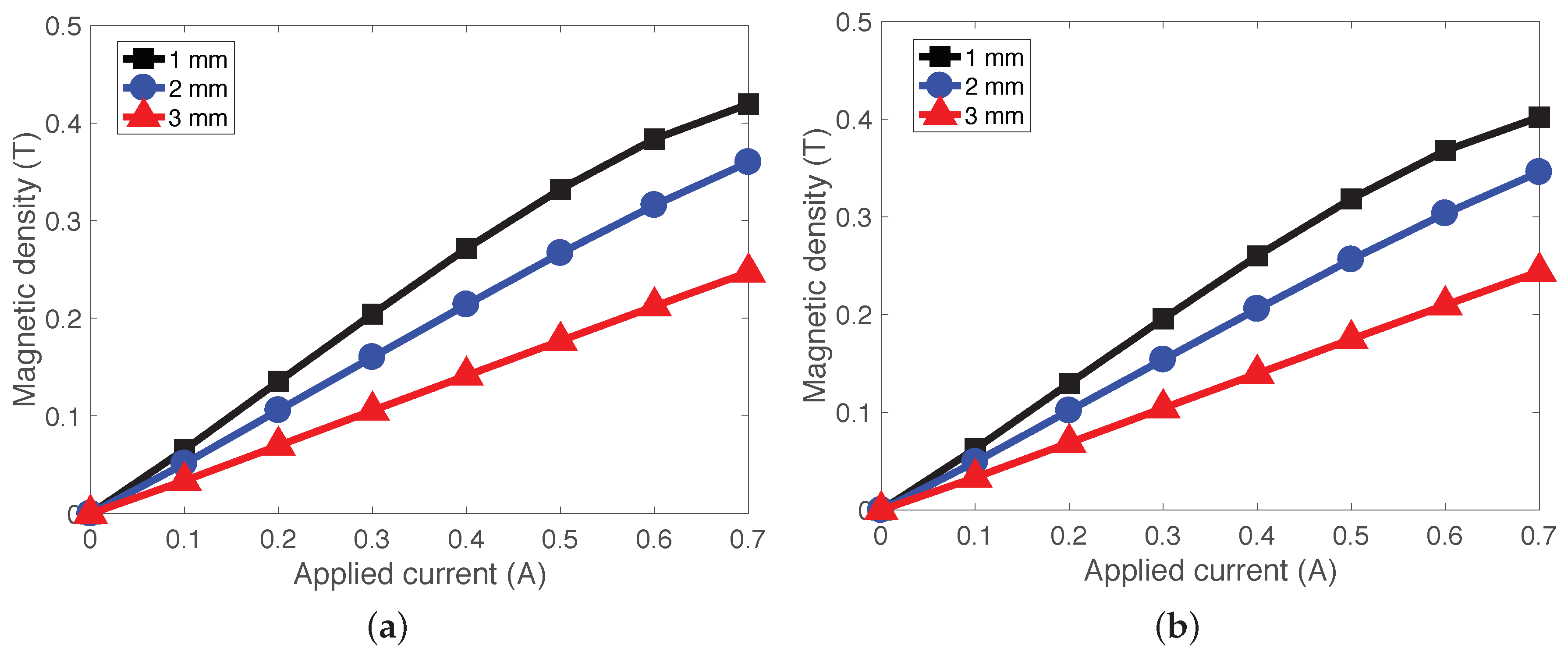
2.1. Electromagnetic Analysis

Figure 2 presents a schematic of the adaptive MRE-DVA used in this study. The MRE-DVA consisted of the electromagnetic coil wound around the bobbin, two MRE pads, and an outer cylinder. The outer cylinder provided the magnetic flux return guides for the magnetic field produced from the electromagnetic coil in the bobbin. The MRE pads, in the shape of a circular tube, were sandwiched between the bobbin and the outer cylinder and attached using adhesive. At stationary status shown in Figure 2a, the MRE pads were not nearly deformed by the magnetic core consisting of the bobbin and electromagnetic coil. However, when a disturbance is applied through the bottom frame or base, the magnetic core is vibrated and the MRE pads are deformed as shown in Figure 2b. On the other hand, in the absence of magnetic field, the MRE pad behaves as a soft (i.e., low spring and low damping) passive rubber isolator. However, when a current input is applied to the electromagnetic coil, the magnetic field generated from the magnetic core activates the MRE pad. The micron-sized iron particles suspended in the activated MRE pad tend to align with the magnetic flux direction. The magnetic interactions between carbonyl Fe particles primarily induce an increase in the stiffness and damping of the MRE pad. Such increments of the stiffness and damping can be rapidly and continuously controlled by the magnetic field strength. Because of this feature of the MRE pad, the MRE-DVA can change its resonant frequency so as to match with the resonant frequency of the target system by adjusting the magnetic field strength.
In order to analytically evaluate the electromagnetic characteristics of the MRE-DVA, a finite element method (FEM) was used in this study. Figure 3 presents one example of the analytical electromagnetic characteristics of the MRE-DVA at an applied current input of 0.7 A. In this design, the outer diameter and height of the DVA were 1.64 inches and 1.25 inches, respectively. The top and bottom active lengths were 0.2 inches that were selected to achieve the desired stiffness of the MRE-DVA and the electromagnetic coil height was 0.7 inches. Two MRE pads were placed at the top and bottom active lengths and each MRE pad height was 0.45 inches. The coil turn number of the electromagnetic coil was 625 and the coil wire was 28 AWG (American wire gauge). The maximum applied current input was 0.7 A that was selected by the maximum allowable current not to burn out the electromagnetic coil wire. The magnetic behavior of the bobbin and the outer cylinder was emulated by the nonlinear B H saturation curve of a low-carbon steel. The magnetic behavior of the MRE pad was assumed to be linear and its relative magnetic permeability was chosen to be three, which was the measured magnetic property for an isotropic MRE with the volume fractions (percentage by volume, vol%) of 30–40% carbonyl Fe particles reported in the reference [47]. As seen in Figure 3a, the magnetic flux generated from the electromagnetic coil was well circulated through a closed path in the confined area. The magnetic flux leakage to the air space surrounding this MRE-DVA was insignificant because there was a significantly large magnetic permeability difference between the low-carbon steel (e.g., μ s t e e l 2000 ) and the air (e.g., μ a i r = 1 ). Thus, the magnetic flux density was well concentrated at the active length areas and its magnetic flux density level was almost uniformed. Three different MRE pad gaps such as 1 mm, 2 mm, and 3 mm were considered in this study. As seen in Figure 3b, the 1 mm gap case presented the highest magnetic flux density over the active length areas. In addition, the magnetic flux density decrement from the 2 mm to the 3 mm gap case was larger than the decrement from the 1 mm to the 2 mm gap case, because the magnetic flux density is inversely proportional to the gap squared. As a result, the lowest magnetic flux density level over the active length areas was obtained in the 3 mm gap case.
Figure 4 presents the analytical magnetic flux densities on the active lengths of the MRE-DVA with respect to the applied current inputs. For the 2 mm and 3 mm gap cases, the magnetic flux density increased almost linearly in response to the applied current input. However, for the 1 mm gap case, the magnetic flux density started to be saturated for applied current inputs above 0.6 A. On the other hand, the magnetic flux density levels for the top and bottom active lengths, as well as their field-dependent behaviors, were very similar.

2.2. MRE Pad Material

The isotropic MRE pad sample was fabricated by randomly dispersing micron-sized carbonyl Fe particles into liquid silicone rubber (Ecoflex, Smooth-On Inc., Macungie, PA, USA) in the absence of a magnetic field. A rapid curing process at room temperature (cure time: 4 h) was used. The composition of the MRE pads was as follows. The Shore number of the liquid silicone rubber was in the range of 0–20 and its volume fraction was 30 vol%. To adjust (for mainly softening purpose) the stiffness of the MRE pad, a 1000 cSt viscosity of silicone oil was added and its volume fraction was 35%. This mixture of the liquid silicone rubber and the silicone oil were mixed and served as the matrix of the MRE composite. The solids loading of the carbonyl Fe powder dispersant was 35 vol%.

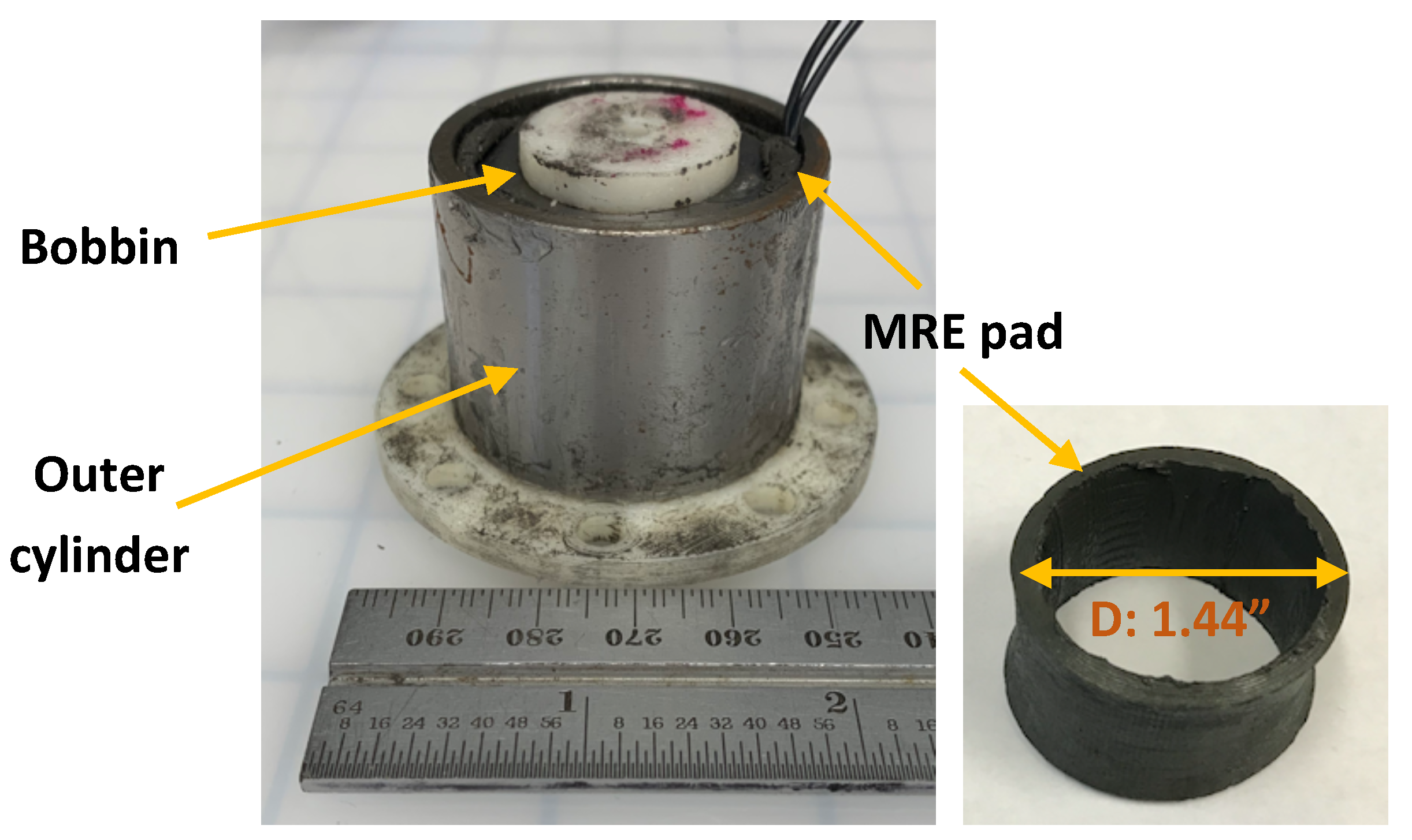
2.3. Fabrication of the MRE-DVA

Figure 5 presents a photograph of the fabricated MRE-DVA. The bobbin and the outer cylinder were made of a low-carbon 12L14 steel and the bottom frame was made of 3D printed plastic material (ABS-P430, Stratasys). In this study, MRE pads with three different thicknesses (i.e., 1 mm, 2 mm, and 3 mm) were fabricated and their effects on the vibration isolation performance of the MRE-DVA were experimentally investigated. To this end, three different MRE-DVAs with different MRE pad thicknesses were fabricated and tested.

3. Damper Force Characteristics of the MRE-DVA

3.1. Complex Stiffness Analysis Method

In order to evaluate the damper force behavior of the MRE-DVA, an Instron material testing system (model: DynaMight 8841) shown in Figure 6 was used. The bottom of the DVA was connected to the fixed load cell and the magnetic core (i.e., bobbin) was attached to the hydraulic actuator. When a sinusoidal excitation displacement was applied to the magnetic core, the damper force of the MRE-DVA was measured by the load cell with respect to different current inputs. The excitation displacement was measured by a linear variable differential transformer (LVDT) built into the hydraulic actuator. The commanded amplitude of the excitation displacement was ± 0.3 mm and the excitation frequencies were 0.1 Hz and 150 Hz. The sampling frequency for the data acquisition in this study was 5 kHz.
On the other hand, complex stiffness analysis was selected for evaluating the damper force characteristics of the MRE-DVA in this study because it has been widely used to characterize the mechanical behaviors of the vibration isolation materials and devices. This complex stiffness analysis is a linearization technique in the frequency domain, which replaces the nonlinear hysteresis damper force loop by an equivalent elliptical viscoelastic damper force loop. In this analysis, the complex stiffness, K * ( ω , i ) is expressed as [48]
K * ( ω , i ) = K ( ω , i ) + j K ( ω , i )
Here, ω is the frequency, i is the current input, and j is the imaginary unit. K ( ω , i ) is the storage stiffness, which is a measure of the energy stored over a cycle and K ( ω , i ) is the loss stiffness, which is a measure of the energy dissipated over a period. The magnitude of the complex stiffness implies the dynamic stiffness, K d ( ω , i ) in this study. That is given by
K d = | K * ( ω , i ) |
Using the storage stiffness and the loss stiffness, the loss factor, η is given by
η = K ( ω , i ) K ( ω , i )
This loss factor was used to evaluate the linearized damping capability of the MRE-DVA corresponding to the nonlinear hysteresis damper force loop. On the other hand, the loss factor, η , is similar to the damping ratio, ζ , of a system at resonance such as
η = 2 ζ = C K M
Here, K, C, and M are the stiffness, viscous damping, and mass of a system. From Equation (4), the loss factor increment implies the increment of the effective viscous damping.

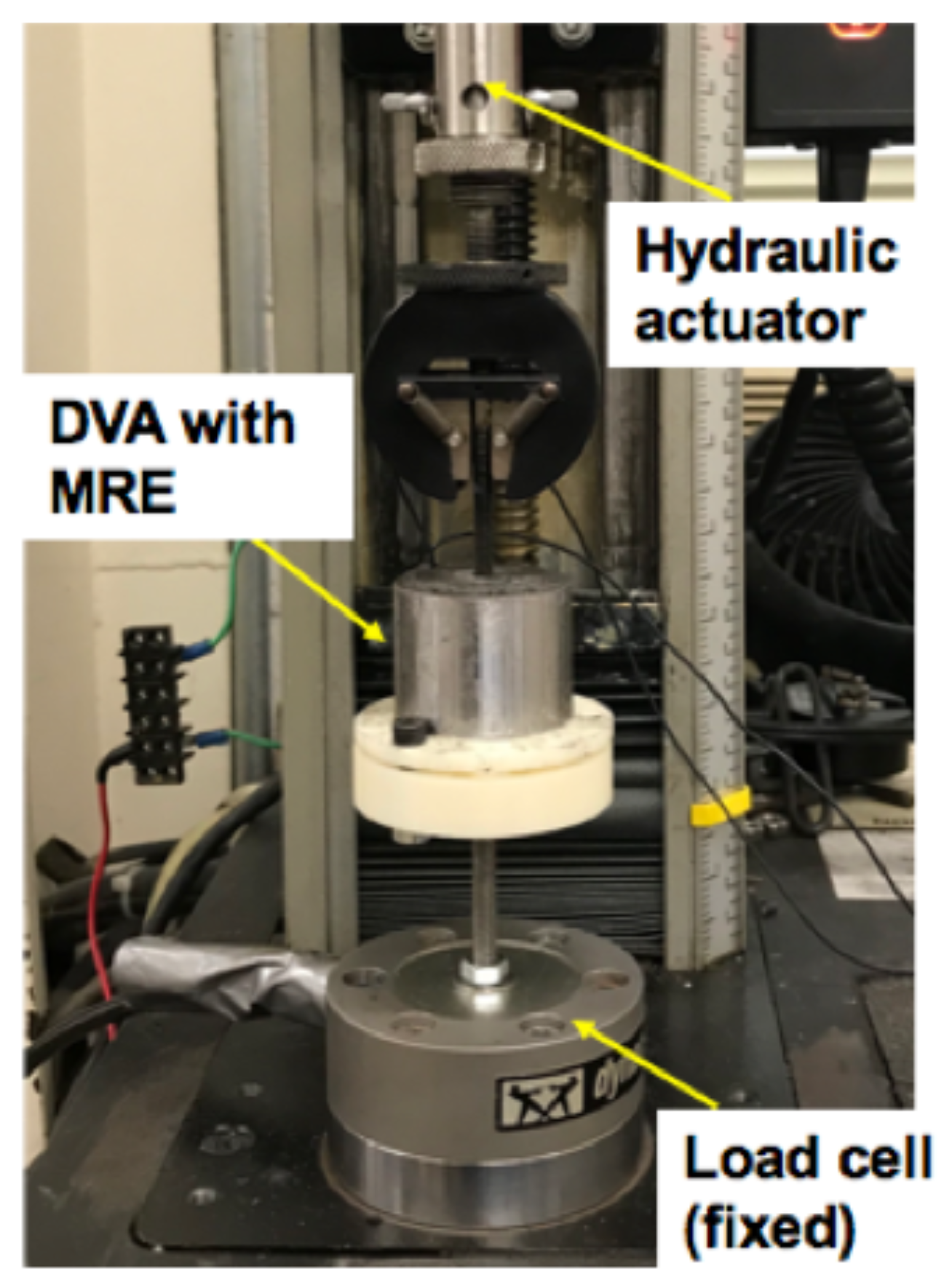
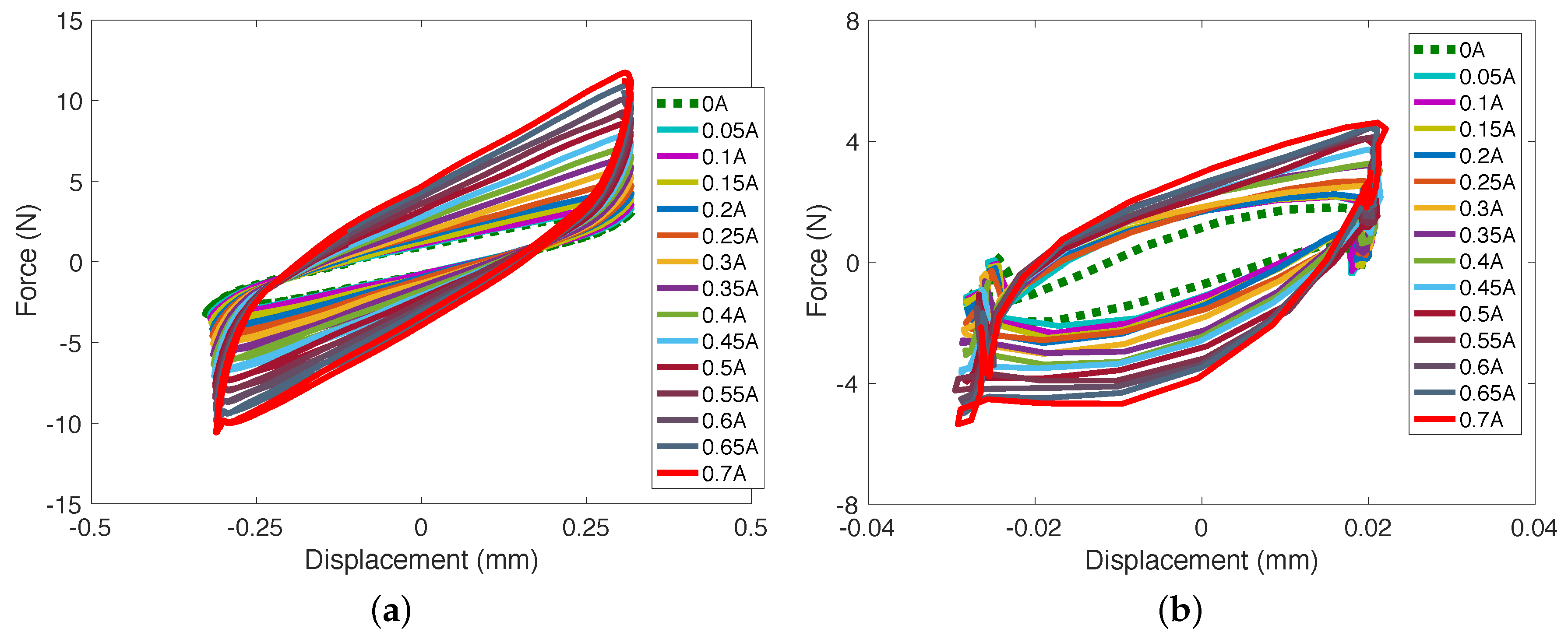
3.2. Experimental Results for the Damper Force Behavior

Figure 7 presents one example of the measured damper force of the MRE-DVA versus the displacement. In this case, the MRE-DVA with 3 mm MRE pad thickness was selected because as observed in the electromagnetic analysis in chapter 2, the lowest magnetic flux density in the active lengths was obtained in the 3 mm MRE pad thickness case. Thus, it was needed to confirm if the MRE-DVA with 3 mm MRE pad thickness produced sufficiently large damper force increment. As seen in Figure 7, the measured excitation displacement at 0.1 Hz was almost the same as the command signal (i.e., ±0.3 mm), but it reduced to almost ±0.03 mm at 150 Hz because of the performance limitation of the hydraulic actuator of the Instron testing machine. On the other hand, the damper force of the MRE-DVA increased as the applied current input increased. At 0.1 Hz excitation input, the shape of the field-on damper force cycle was similar to the rectangle. This physically implies that the MRE-DVA produced the damper force like nonlinear Coulomb friction damping force due to the yield stress of the MRE. In addition, the inclined slope of the damper force cycle physically implies the stiffness. As the current increased, the inclined slope became steeper. In addition, the enclosed area of the damper force cycle also increased. The enclosed area physically implies the viscous damping. In response to the applied current input, the MRE-DVA could increase the damping as well as the stiffness at the same time. On the other hand, at as high as 150 Hz excitation input, the shape of the field-on damper force turned into the elliptical shape. This physically implies that the MRE-DVA at a much higher frequency showed adjustable viscoelastic damping behavior. In addition, the initial twist at both ends of the force-displacement plot at 150 Hz excitation input was observed. This phenomenon may result from the occurrence of other dynamics by not only vertical motion, but also rocking motion due to the high frequency vibration.
Figure 8 presents the complex stiffness analysis of the MRE-DVA in the frequency domain. In this case, the excitation frequencies were changed to 0.1, 25, 50, 75, 100, 125, 150 Hz. As seen in this figure, the dynamic stiffness, K d ( ω , i ) , showed linear behavior with the frequency in the frequency range of 0–50 Hz, but started to exponentially increase with the frequency after 50 Hz. On the other hand, the loss factor, η , at the frequency range of 0–50 Hz increased with the applied current input. At the frequency range of 50–100 Hz, the loss factor was hardly changed by the applied current input. However, after 100 Hz, the loss factor decreased with the applied current input. This phenomenon implies that the loss stiffness, K ( ω , i ) increment was larger than the storage stiffness, K ( ω , i ) increment in response to the applied current input until the frequency reached 50 Hz. In other words, the damping increment of the MRE-DVA by the applied current input was larger than its stifness increment. However, at the frequency range of 50–100 Hz, the storage stiffness increment with respect to the applied current inputs was almost similar to the loss stiffness increment. Finally, after 100 Hz, the storage stiffness increment by the applied current inputs was larger than the loss stiffness increment. In other words, the stiffness increment of the MRE-DVA by the applied current was larger than the damping increment after 100 Hz. Such trends can be also observed in the studies published by other researchers [49,50,51]. This phenomenon may result from the interaction between the iron particles and the matrix [52]. At the lower current input and high frequency vibration, the particle-particle interaction induced by the magnetic field can increase the interfacial friction between the particles and the matrix, thereby increasing the loss factor. However, at the higher current input and high frequency vibration, the stronger magnetic fields hold the iron particles very tightly in parallel to the magnetic flux direction, thus decreasing the interaction between the particles and the matrix. This caused an increase in the dynamic stiffness of the MRE-DVA but a decrease in the loss factor at the high current input and high frequency vibration. Figure 8e showed the dynamic range, DR , which is defined as the ratio of the dynamic stiffness at a current input to the dynamic stiffness at no current input, K d ( ω , i = 0 A ) , mathematically represented by
DR = K d ( ω , i ) K d ( ω , i = 0 A )
As seen in Figure 8e, the dynamic range over the tested frequency range was DR 2 at relatively higher current inputs (above 0.5 A). This implies that the dynamic stiffness at the current input above 0.5 A was at least two times as large as that at no current input. In addition, this dynamic range is related to the resonant frequency adaptability of the MRE-DVA. Using this dynamic range value, DR 2 , the resonant frequency, ω n , i = 0.5 A of the MRE-DVA at the current input of above 0.5 A was estimated to be shifted from ω n , i   =   0 A to ω n , i   =   0.5 A 2 ω n , i   =   0 A . Here, ω n , i   =   0 A is the resonant frequency of the MRE-DVA at no current input.

4. Vibration Isolation Performance of the MRE-DVA

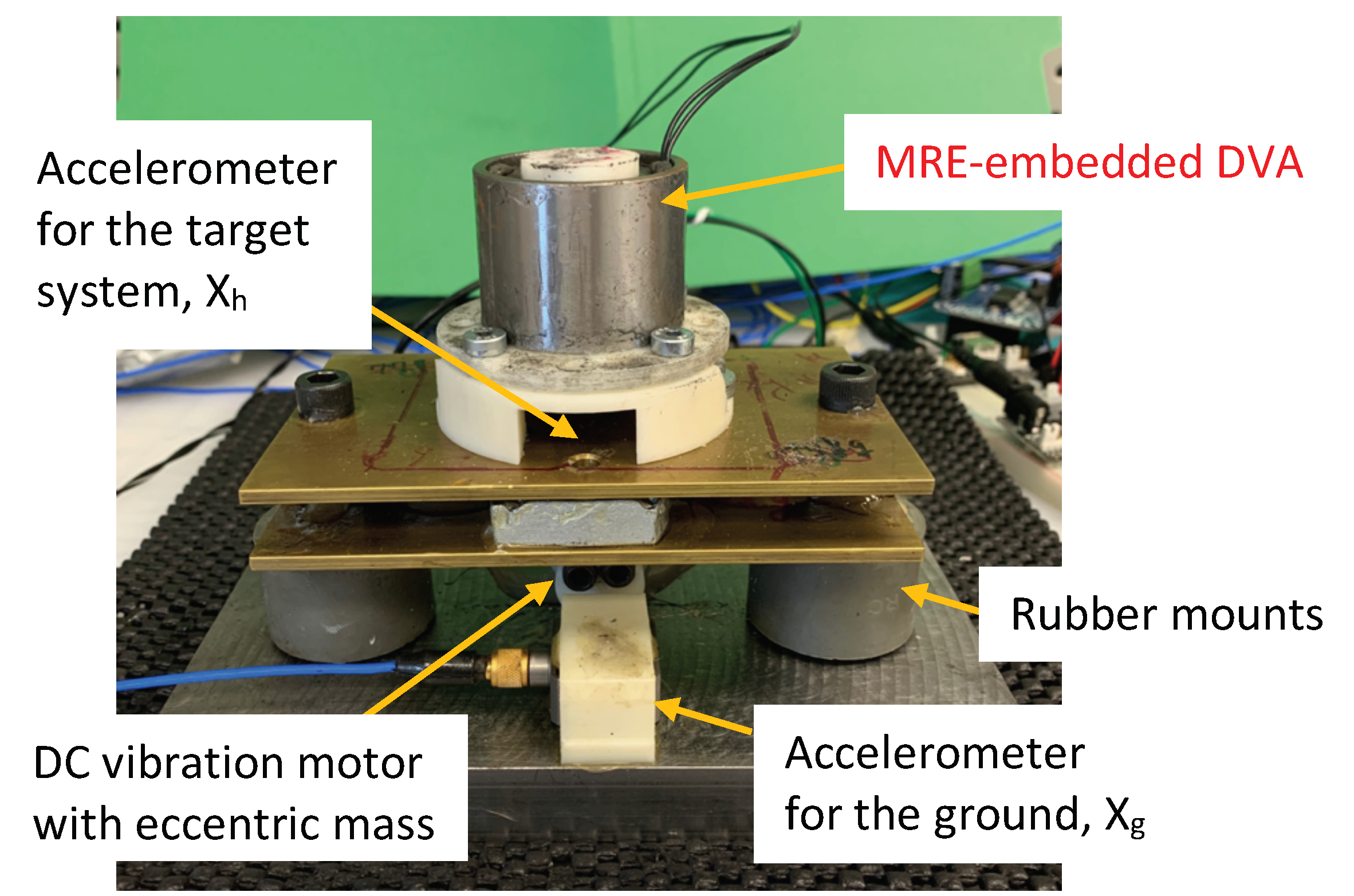
4.1. Experimental Setup and Results

Figure 9 presents the testing setup for measuring the frequency response of the target system with the MRE-DVA. The mass of the target system was 1027 g and the rubber mounts worked as a supporter of the target mass and also the stiffness and damping components of the target system. To excite the target mass, the eccentric vibrating motor with an eccentric mass of 4 g was configured at the bottom base. The rpm of the eccentric vibrating motor was swept by using the DC motor controller to excite the target mass up to 250 Hz. To measure the vibrations of the target mass and the bottom base, the accelerometers were placed atop the target mass and also the bottom base. The measured accelerations of the target mass and the bottom base were stored at the computer through the data acquisition device. In Figure 9, the displacement of the bottom base was denoted by X g , and the displacement of the target mass was denoted by X h . In this study, the excitation amplitude of X g was about ± 0.75 G at 150 Hz. Here G is the gravitational acceleration. This corresponds to the displacement amplitude of about ±8.3 μ m at 150 Hz.
Figure 10 presents the vibration isolation performance of the MRE-DVA for a 3 mm pad thickness. Testing was conducted for current ranging in the electromagnet from 0 to 0.7 A. As seen in this figure, the MRE-DVA could improve the vibration isolation performance over the baseline system with no DVA. Initially, the target system with the MRE-DVA at zero current input had a resonance frequency of about 170 Hz, and a nominal crossover frequency of about 220 Hz. As the current increased, the vibration at the resonant frequency of around 170 Hz was significantly reduced. However, for current inputs larger than 0.35 A, the resonant frequency significantly shifted to a lower frequency of about 135 Hz. As the current increased further, the vibration at the resonant frequency of about 135 Hz became larger and the resonant frequency slightly shifted again to the right side (i.e., toward a higher frequency) in the frequency domain.

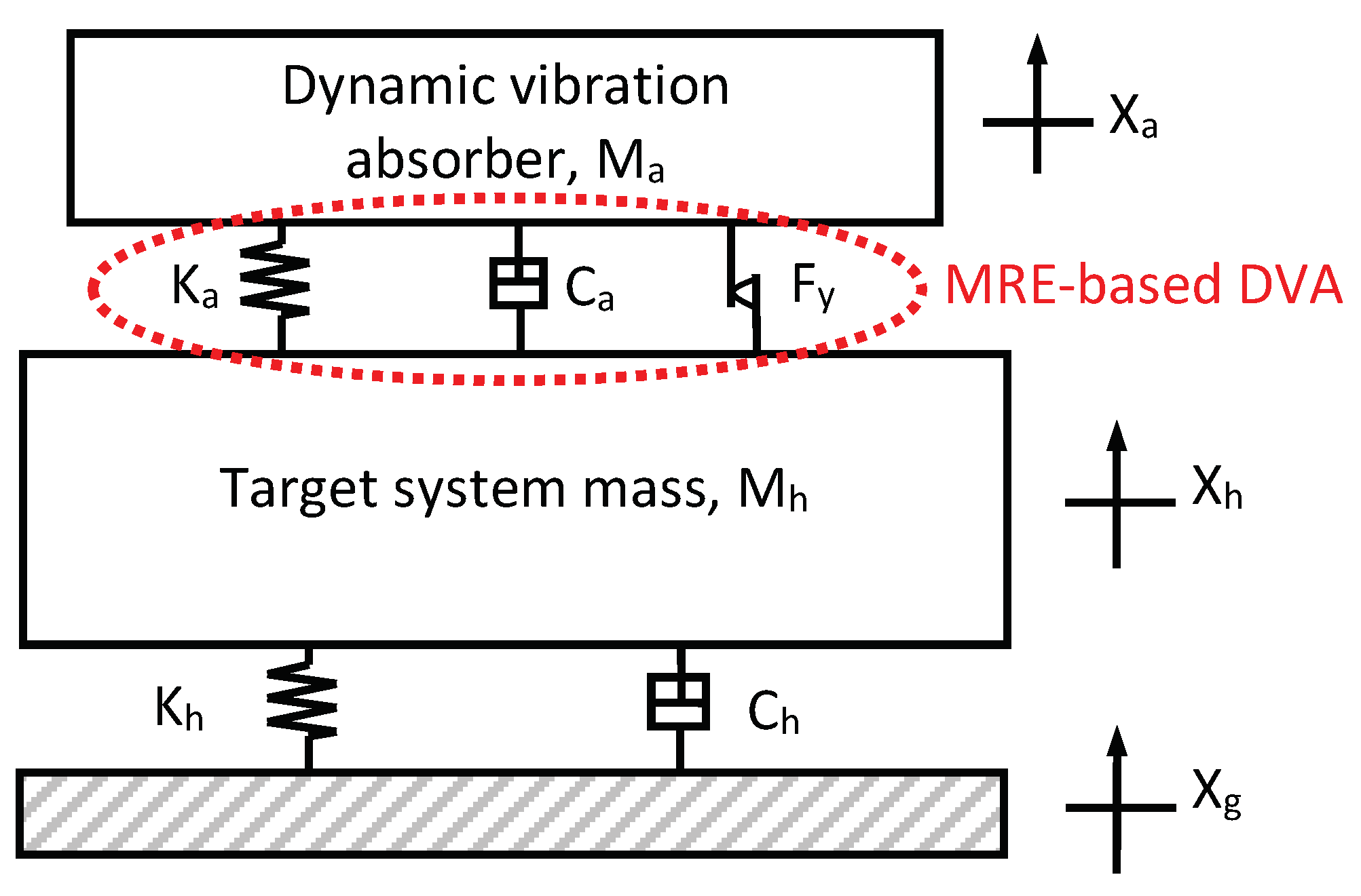
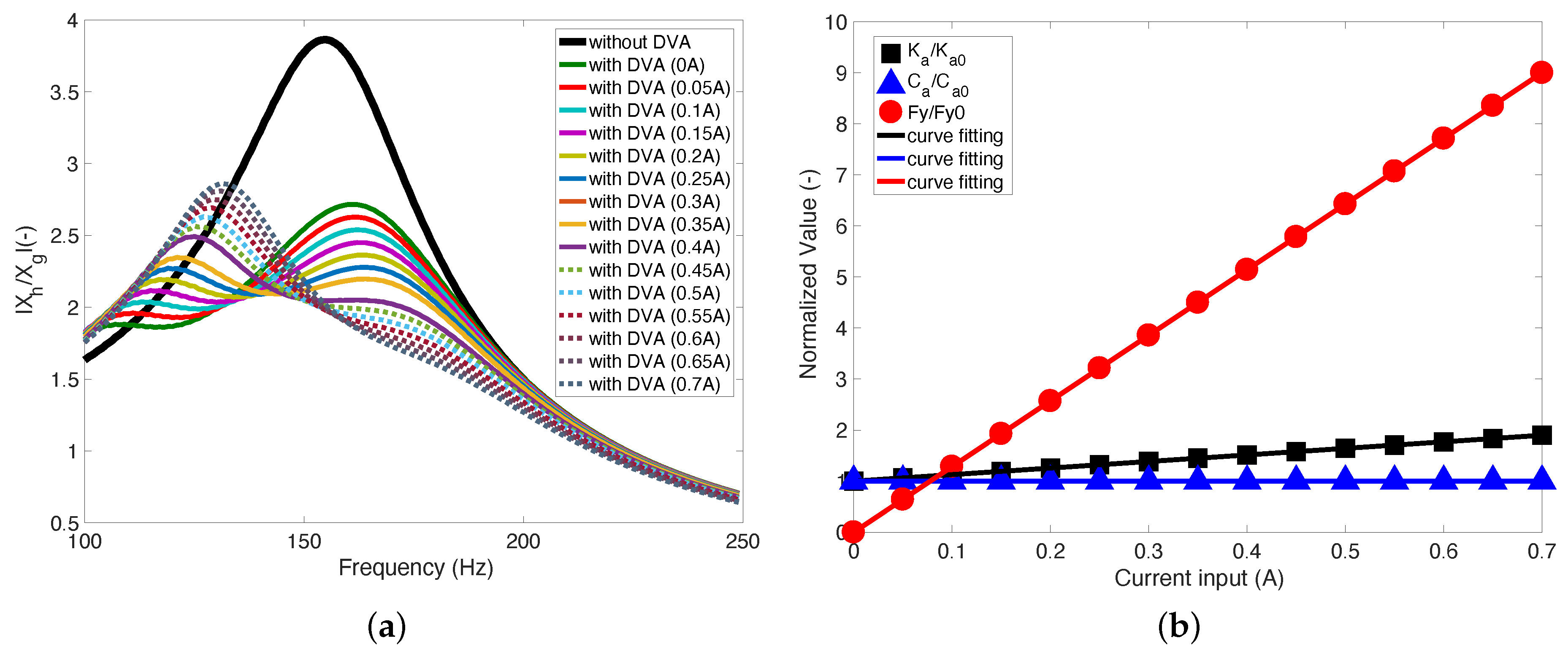
4.2. Equivalent Mechanical Model of the MRE-DVA

Figure 11 presents the equivalent mechanical model of the MRE-DVA. As seen in this figure, the MRE-DVA consisted of a stiffness K a , a viscous damping C a and a Coulomb friction damping force (i.e., yield force) F y . The damper force of the MRE-DVA, F a is given.
F a = K a ( X a X h ) + C a ( X ˙ a X ˙ h ) + F y s i g n ( X ˙ a X ˙ h )
Here, X a and X ˙ a are the displacement and velocity of the MRE-DVA, respectively. X ˙ h is the velocity of the target system. s i g n ( · ) is the signum function. The governing equation of a motion for the equivalent mechanical model of the MRE-DVA is obtained as follows:
M a X a ¨ = F a
M h X h ¨ = F a K h ( X h X g ) C h ( X ˙ h X ˙ g )
Here, K h and C h are the stiffness and viscous damping of the target system, respectively. X ˙ g is the velocity of the excitation.
Figure 12 presents the simulated vibration isolation performance and identified system parameters of the MRE-DVA using the equivalent mechanical model. As seen in this figure, the simulated vibration isolation performance could well capture the behavior of the measured vibration isolation performance shown in Figure 10. The normalized system parameters identified through this simulated vibration isolation responses are presented in Figure 12b. In this figure, K a 0 and C a 0 are the stiffness and viscous damping at no current input. F y 0 is the Coulomb friction damping force at a current input of 0.05 A. Using these values, the identified system parameters shown in Figure 12b were normalized. The identified system parameters are listed in Table 2. As expected from the experimental behavior of the MRE-DVA shown in Figure 10, the stiffness and Coulomb friction damping force of the MRE-DVA increased when the current input increased. Especially, the Coulomb friction damping force increment was significantly larger than the stiffness increment. However, the viscous damping of the MRE-DVA was kept constant. Thus, the stiffness and Coulomb friction damping force increments caused to significantly shift the resonant frequency of the MRE-DVA toward lower frequency ranges. The identified stiffness, viscous damping, and Coulomb friction damping force of the MRE-DVA can be expressed as a linear function of current input as follows:
K a = 79 , 573 i + K a 0 [ N / m ]
C a = C a 0 [ N · s / m ]
F y = 5.14 i [ N ]
As seen in Figure 12b, the curve-fitted functions well captured the identified system parameters of the MRE-DVA. From Equations (9)–(11), it was again confirmed that the stiffness and Coulomb friction damping force of the MRE-DVA were proportional to the current input. However, the viscous damping of the MRE-DVA did not depend on the current input. This behavior of the MRE-DVA used in this study is similar to an ideal Bingham plastic damper force model in which a viscous damping force is independent with the current input but a yield force is a function of the current input.

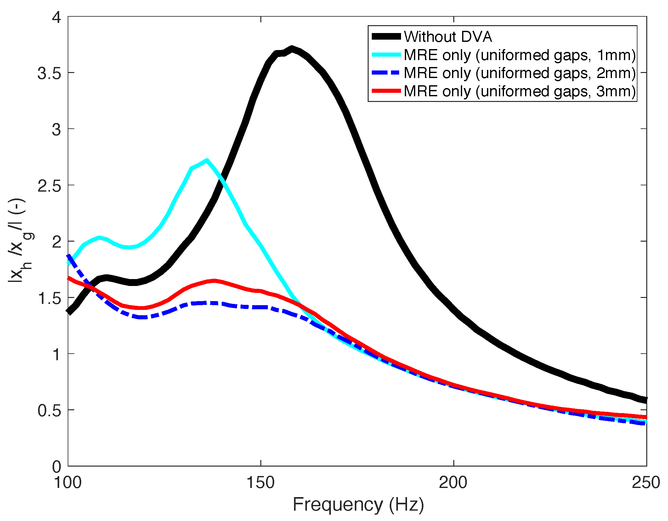
4.3. Effect of the MRE Pad Thickness

Figure 13 presents the effect of the MRE pad thickness on the vibration isolation performances of the MRE-DVAs. In this case, three different MRE pad thicknesses such as 1 mm (seen in Figure 13a), 2 mm (seen in Figure 13b), and 3 mm (seen in Figure 10) were tested. As seen in these figures, the case of 1 mm thickness did not particularly show the vibration isolation improvement over the baseline system with no DVA because the passive (i.e., zero current input) stiffness of the DVA at 1 mm MRE pad thickness became too large (please refer to Appendix A) As a result, the moving mass of the DVA worked like an almost lumped mass attached to the target mass and could not much improve the vibration isolation performance of the baseline system with no DVA. On the other hand, as seen in these figures, the resonant frequency of the MRE-DVA with 1 mm MRE pad thickness shifted only to the right side in the frequency domain, as the applied current input increased. However, for the cases of 2 mm and 3 mm MRE pad thicknesses, the resonant frequency of the MRE-DVA initially shifted to the right side at current inputs lower than 0.4 A. However, at a current input of 0.4 A, the resonant frequency jumped to the left side (i.e., from about 170 Hz to about 135 Hz). For further current inputs, the resonant frequency shifted again to the right side.
Figure 14 presents the comparison on the minimum envelopes of the vibration isolation performance for three different MRE pad thicknesses. First, it should be noted that these minimum envelopes in the frequency domain were extracted from Figure 10 and Figure 13 under the assumption that optimal current inputs at each frequency were applied to the MRE-DVAs. As clearly observed in this figure, the 2 mm and 3 mm MRE pad thickness improved the vibration isolation performance of the baseline system with no DVA over most of its tested frequency range. However, if considering the vibration magnitude reduction around the resonant frequency, the 2 mm thickness case showed a slightly better performance than the 3 mm thickness case. In contrast, the 1 mm thickness case showed good vibration isolation performance around the resonant frequency of the target system. However, because of the too stiff system, the vibration isolation performance was deteriorated at the frequency range below the resonant frequency of the target system. On the other hand, it should be noted that the MRE-DVA used in this study was aimed at reducing the steady-state vibration of the target system at a periodic excitation condition, not for transient and random vibrations. In addition, this MRE-DVA is not an active actuator but a semi-active actuator, in which its stiffness and damping can be adjusted by an applied current input. Thus, the response time of this MRE-DVA was not an important factor for this study.
Figure 15 presents the power consumption of the MRE-DVA. The maximum power consumption of the MRE-DVA used in this study was as small as nominally 6.1 W at a current input of 0.7 A.

5. Conclusions

In this study, the vibration isolation performance of the magnetorheological elastomer (MRE)-based dynamic vibration absorber (MRE-DVA) for mitigating the high frequency vibrations (100–250 Hz) was experimentally investigated. From the results presented in this study, the following conclusions were obtained.
  • To soften the stiffness of the MRE pads, a silicone oil was added to the mixture of the liquid silicone rubber and carbonyl Fe particles before curing.
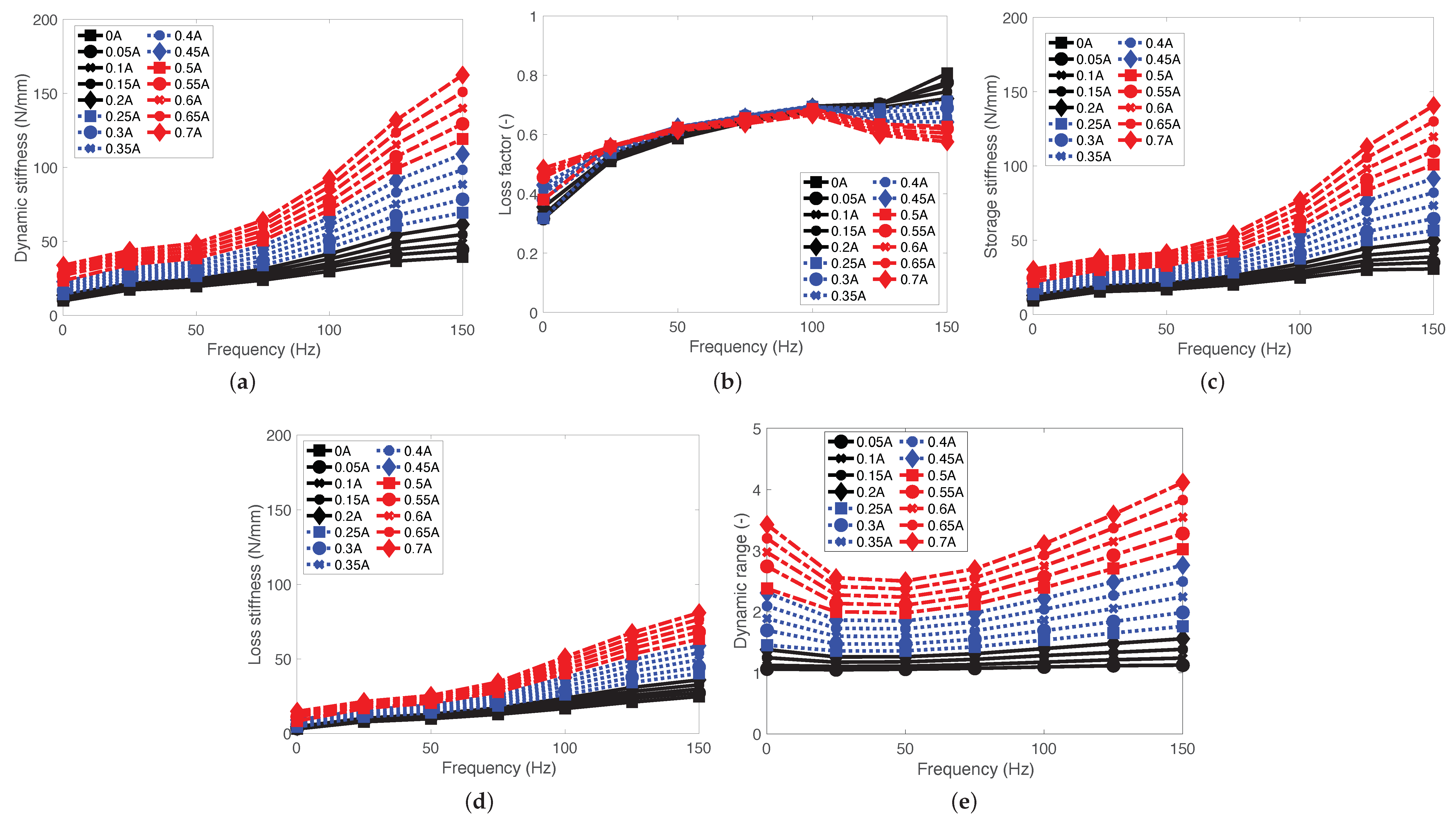
  • From the complex stiffness analysis for the damper force cycle, it was confirmed that the dynamic range (DR) was DR 2 at a relatively higher current input of above 0.5 A over the tested frequency range.
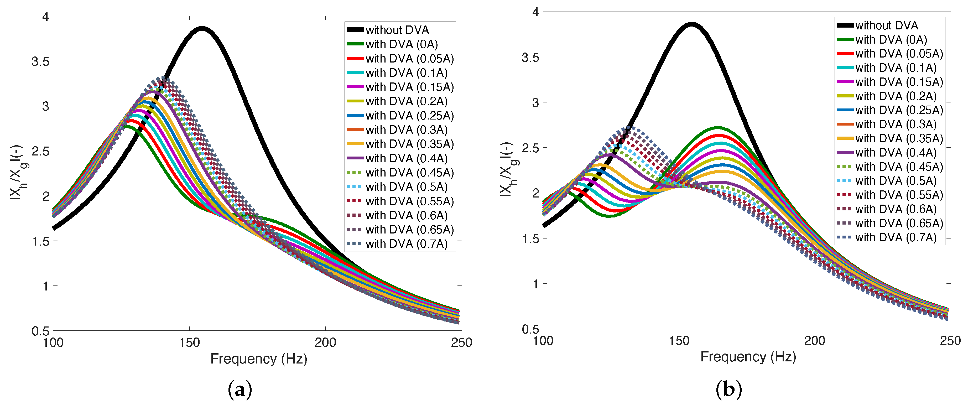
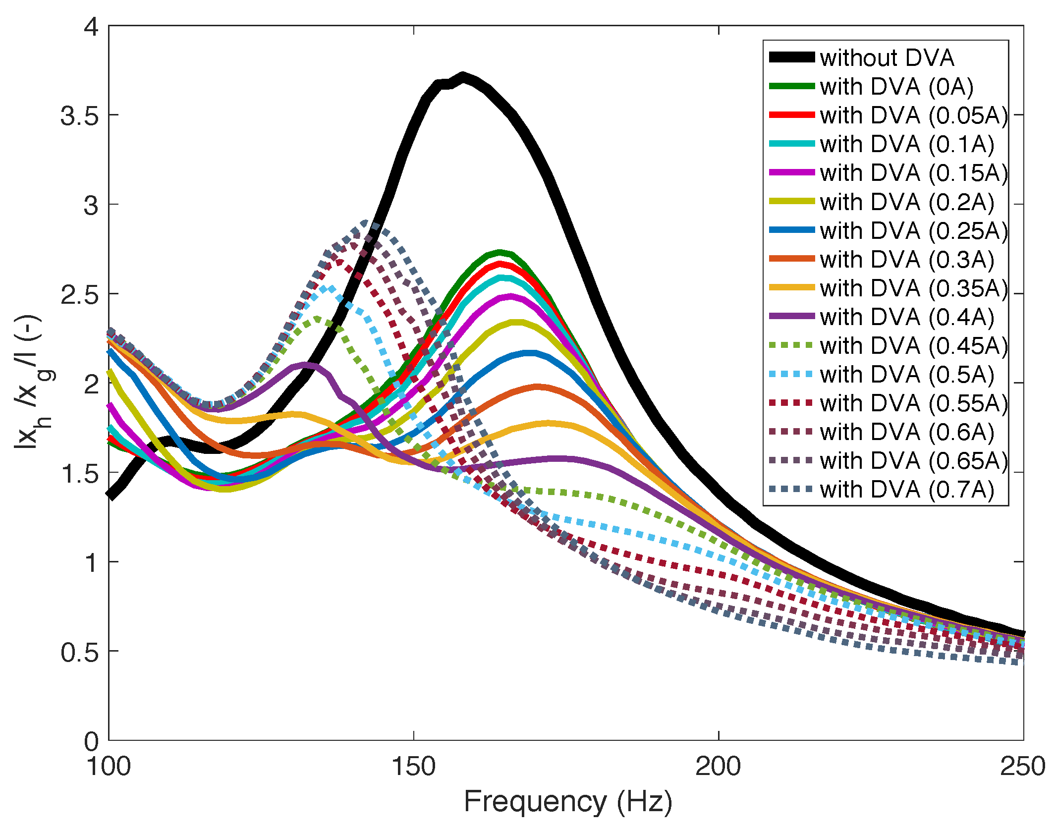
  • From the vibration isolation testing, it was observed that the resonant frequencies of the MRE-DVAs could be substantially adjusted using an applied current input. For the 2 mm and 3 mm MRE pad thickness cases, the adjustable resonant frequency range by the current input was about 135–170 Hz. However, for the 1 mm MRE pad thickness case, the resonant frequency change was small because it was initially too stiff for no current input (0 A).
  • From the minimum envelopes shown the in vibration frequency response plots for the tested frequency range from 100 Hz to 250 Hz, it was demonstrated that the system with the MRE-DVAs achieved much better vibration isolation performance than the baseline system with no DVA.
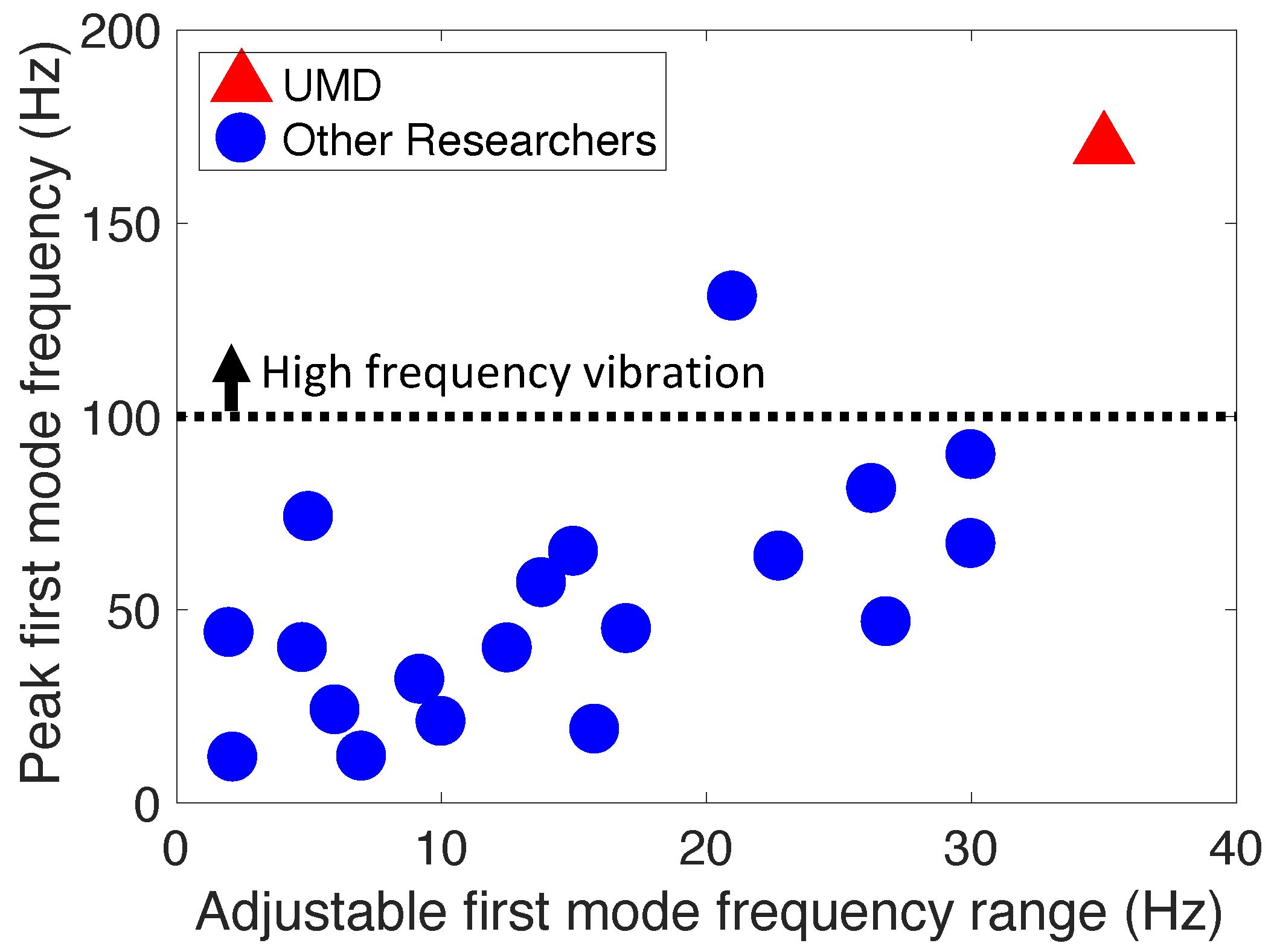
  • It was confirmed that the design of the MRE-DVAs used in this study was simple but effective to reduce the vibration of the target system for the high frequency vibrations (i.e., 100–250 Hz).
As a future work, the reliability and endurability of the MRE-DVA need to be investigated. In addition, an appropriate control algorithm for this adaptive MRE-DVA will be developed in future.

Author Contributions

Y.C. and N.M.W. equally contributed. All authors have read and agreed to the published version of the manuscript.

Funding

This research received no external funding.

Institutional Review Board Statement

Not applicable.

Informed Consent Statement

Not applicable.

Data Availability Statement

Not applicable.

Conflicts of Interest

The authors declare no conflict of interest.

Appendix A

Figure A1 presents the simulated vibration isolation performances of the MRE-DVAs using the equivalent mechanical model for the 1 mm and 2 mm MRE pad thickness cases. In this figure, the curves of the normalized system parameters were exactly the same as the curve of Figure 12b, but the values of the identified system parameters were different as shown in Table A1. If comparing Figure A1 to Figure 13, the equivalent mechanical model could still capture the behaviors of the measured vibration isolation performance of the MRE-DVAs with the 1 mm and 2 mm MRE pad thicknesses well.
Figure A1. Simulated vibration isolation performances of the MRE-DVAs using the equivalent mechanical model: (a) 1 mm thickness and (b) 2 mm thickness.
Actuators 11 00157 g0a1
Table A1. The identified system parameters for the MRE-DVAs with the 1 mm, 2 mm and 3 mm MRE pad thicknesses.
           VariablesValues
For the 1 mm MRE pad thickness case
         Stiffness of the MRE-DVA at no current input, K a 0 107.8 kN/m
         Viscous damping of the MRE-DVA at no current input, C a 0 45.9 N · s/m
         Coulomb friction damping force (i.e., yield force), F y 0 0.51 N
         of the MRE-DVA at a current input of 0.05 A
For the 2 mm MRE pad thickness case
         Stiffness of the MRE-DVA at no current input, K a 0 67.2 kN/m
         Viscous damping of the MRE-DVA at no current input, C a 0 27.2 N · s/m
         Coulomb friction damping force (i.e., yield force), F y 0 0.39 N
         of the MRE-DVA at a current input of 0.05 A
For the 3 mm MRE pad thickness case
         Stiffness of the MRE-DVA at no current input, K a 0 60.9 kN/m
         Viscous damping of the MRE-DVA at no current input, C a 0 34.5 N · s/m
         Coulomb friction damping force (i.e., yield force), F y 0 0.26 N
         of the MRE-DVA at a current input of 0.05 A

References

  1. Hua, Y.; Wong, W.; Cheng, L. Optimal Design of a Beam-Based Dynamic Vibration Absorber Using Fixed-Points Theory. J. Sound Vib. 2018, 421, 111–131. [Google Scholar] [CrossRef]
  2. Phuc, V.; Tran, V.T. Optimization Design for Multiple Dynamic Vibration Absorbers on Damped Structures Using Equivalent Linearization Method. Proc. Inst. Mech. Eng. J. Multi-Body Dyn. 2021, 236, 41–50. [Google Scholar] [CrossRef]
  3. Ormondroyd, J.; Hartog, J.P.D. The Theory of Dynamic Vibration Absorber. ASME J. Appl. Mech. 1928, 50, 9–22. [Google Scholar]
  4. Yang, C.; Li, D.; Cheng, L. Dynamic Vibration Absorbers for Vibration Control within a Frequency Band. J. Sound Vib. 2011, 330, 1582–1598. [Google Scholar] [CrossRef]
  5. Brock, J.E. A Note on the Damped Vibration Absorber. ASME J. Appl. Mech. 1946, 13, A284. [Google Scholar] [CrossRef]
  6. Sun, J.Q.; Jolly, M.R.; Norris, M.A. Passive, Adaptive and Active Tuned Vibration Absorbers-A Survey. ASME J. Vib. Acoust. 1995, 117, 234–242. [Google Scholar] [CrossRef]
  7. Inman, D.J. Engineering Vibration; Prentice-Hall: Hoboken, NJ, USA, 2001. [Google Scholar]
  8. McDaid, A.J.; Mace, B.R. A Self-Tuning Electromagnetic Vibration Absorber with Adaptive Shunt Electronics. Smart Mater. Struct. 2013, 22, 105013. [Google Scholar] [CrossRef]
  9. Gonzalez-Buelga, A.; Clare, L.R.; Neild, S.A.; Burrow, S.G.; Inman, D.J. An Electromagnetic Vibration Absorber with Harvesting and Tuning Capabilities. Struct. Control Health Monit. 2015, 22, 1359–1372. [Google Scholar] [CrossRef]
  10. Herold, S.; Mayer, D. Adaptive Piezoelectric Absorber for Active Vibration Control. Actuator 2016, 5, 7. [Google Scholar] [CrossRef]
  11. Herold, S.; Mayer, D.; Roglin, T. Design and Testing of a Piezoelectric Inertial Mass Actuator for Active Vibration Control. Vib. Eng. Technol. Mach. 2014, 23, 587–597. [Google Scholar] [CrossRef]
  12. Mani, Y.; Senthikumar, M. Shape Memory Alloy-Based Adaptive-Passive Dynamic Vibration Absorber for Vibration Control in Piping Application. J. Vib. Control 2015, 21, 1838–1847. [Google Scholar] [CrossRef]
  13. Kumbhar, S.B.; Chavan, S.P.; Gawade, S.S. Adaptive Tuned Vibration Absorber Based on Magnetorheological Elastomer-Shape Memory Alloy Composite. Mech. Syst. Signal Process. 2018, 100, 208–223. [Google Scholar] [CrossRef]
  14. Liao, G.J.; Gong, X.L.; Kang, C.J.; Xuan, S.H. The Design of an Active-Adaptive Tuned Vibration Absorber Based on Magnetorheological Elastomer and its Vibration Attenuation Performance. Smart Mater. Struct. 2011, 20, 075015. [Google Scholar] [CrossRef]
  15. Li, Y.; Li, J.; Tian, T.; Li, W. A Highly Adjustable Magnetorheological Elastomer Based Isolator for Applications of Real-Time Adaptive Control. Smart Mater. Struct. 2013, 22, 095020. [Google Scholar] [CrossRef]
  16. Komatsuzaki, T.; Iwata, Y. Design of a Real-Time Adaptively Tuned Dynamic Vibration Absorber with a Variable Stiffness Property Using Magnetorheological Elastomer. Shock Vib. 2015, 2015, 676508. [Google Scholar] [CrossRef]
  17. Sun, S.; Deng, H.; Yang, J.; Li, W.; Du, H.; Alici, G.; Nakano, M. An Adaptive Tuned Vibration Absorber Based On Multilayered MR Elastomers. Smart Mater. Struct. 2015, 24, 045045. [Google Scholar] [CrossRef]
  18. Xin, F.L.; Bai, X.X.; Qian, L.L. Principle, Modeling, and Control of a Magnetorheological Elastomer Dynamic Vibration Absorber for Powertrain Mount Systems of Automobiles. J. Intell. Mater. Syst. Struct. 2017, 3, 2239–2254. [Google Scholar] [CrossRef]
  19. Bastola, A.K.; Li, L. A New Type of Vibration Isolator Based on Magnetorheological Elastomer. Mater. Des. 2018, 157, 431–436. [Google Scholar] [CrossRef]
  20. Bian, Y.; Liang, X.; Gao, Z. Vibration Reduction for a Flexible Arm Using Magnetorheological Elastomer Vibration Absorber. Shock. Vib. 2018, 2018, 9723538. [Google Scholar] [CrossRef]
  21. Yang, J.; Sun, S.S.; Ning, D.; Li, Z.; Deng, L.; Christie, M.; Du, H.; Zhang, S.W.; Li, W.H. Development and Evaluation of a Highly Adaptive MRF-Based Absorber with a Large Effective Frequency Range. Smart Mater. Struct. 2019, 28, 105003. [Google Scholar] [CrossRef]
  22. Komatsuzaki, T.; Inoue, T.; Iwata, Y. Experimental Investigation of an Adaptively Tuned Dynamic Absorber Incorporating Magnetorheological Elastomer with Self-Sensing Property. Exp. Mech. 2016, 56, 871–880. [Google Scholar] [CrossRef]
  23. Deng, H.X.; Gong, X.L. Application of Magnetorheological Elastomer to Vibration Absorber. Commun. Nonlinear Sci. Numer. Simul. 2008, 13, 1938–1947. [Google Scholar] [CrossRef]
  24. Gao, P.; Liu, H.; Xiang, C.; Yan, P.; Mahmoud, T. A New Magnetorheological Elastomer Torsional Vibration Absorber: Structural Design and Performance Test. Mech. Sci. 2021, 12, 321–332. [Google Scholar] [CrossRef]
  25. Sinko, R.; Karnes, M.; Koo, J.H.; Kim, Y.K.; Kim, K.S. Design and Test of an Adaptive Vibration Absorber Based on Magnetorheological Elastomers and a Hybrid Electromagnet. J. Intell. Mater. Syst. Struct. 2012, 24, 803–812. [Google Scholar] [CrossRef]
  26. Xu, Z.; Gong, X.; Liao, G.; Chen, X. An Active-Damping-Compensated Magnetorheological Elastomer Adaptive Tuned Vibration Absorber. J. Intell. Mater. Syst. Struct. 2010, 21, 1039–1047. [Google Scholar] [CrossRef]
  27. Liu, G.; Lu, K.; Zou, D.; Xie, Z.; Rao, Z.; Ta, N. Development of a Semi-Active Dynamic Vibration Absorber for Longitutdinal Vibration of Propulsion Shaft System Based on Magnetorheological Elastomer. Smart Mater. Struct. 2017, 26, 075009. [Google Scholar] [CrossRef]
  28. Deng, H.X.; Gong, X.L. Adaptive Tuned Vibration Absorber Based on Magnetorheological Elastomers. J. Intell. Mater. Syst. Struct. 2007, 18, 1205–1210. [Google Scholar] [CrossRef]
  29. Komatsuzaki, T.; Inoue, T.; Terashima, O. A Broadband Frequency-Tunable Dynamic Absorber for the Vibration Control of Structures. J. Phys. Conf. Ser. 2016, 744, 012167. [Google Scholar] [CrossRef]
  30. Komatsuzaki, T.; Inoue, T.; Terashima, O. Broadband Vibration Control of a Structure by Using a Magnetorheological Elastomer-Based Tuned Dynamic Absorber. Mechatronics 2016, 40, 128–136. [Google Scholar] [CrossRef]
  31. Sun, S.; Chen, Y.; Yang, Y.; Tian, T.; Deng, H. The Development of an Adaptive Tuned Magnetorheological Elastomer Absorber Working in Squeeze Mode. Smart Mater. Struct. 2014, 23, 075009. [Google Scholar] [CrossRef]
  32. Deng, H.X.; Gong, X.L.; Wang, L.H. Development of an Adaptive Tuned Vibration Absorber with Magnetorheological Elastomer. Smart Mater. Struct. 2006, 15, N111–N116. [Google Scholar] [CrossRef]
  33. Jeong, U.C. Application of Adaptive Tuned Magneto-Rheological Elastomer for Vibration Reduction of a Plate by a Variable-Unbalance Excitation. Appl. Sci. 2020, 10, 3934. [Google Scholar] [CrossRef]
  34. Samal, S.; Skodova, M.; Abate, L.; Blanco, I. Magneto-Rheological Elastomer Composite. A Review. Appl. Sci. 2020, 10, 4899. [Google Scholar] [CrossRef]
  35. Samal, S.; Vlach, J.; Kavan, P. Improved Mechanical Properties of Magneto Rheological Elastomeric Composite with Isotropic Iron Filler Distribution. Cienc. Tecnol. dos Mater. 2016, 28, 155–161. [Google Scholar] [CrossRef]
  36. Hartzell, C.M.; Choi, Y.T.; Wereley, N.M.; Leps, T.J. Performance of a Magnetorheological Fluid-Based Robotic End Effector. Smart Mater. Struct. 2019, 28, 035030. [Google Scholar] [CrossRef]
  37. Choi, Y.T.; Hartzell, C.M.; Leps, T.; Wereley, N.M. Gripping Characteristics of an Electromagnetically Activated Magnetorheological Fluid-Based Gripper. AIP Adv. 2018, 8, 056701. [Google Scholar] [CrossRef]
  38. Xie, L.; Choi, Y.T.; Liao, C.R.; Wereley, N.M. Long Term Stability of Magnetorheological Fluids Using High Viscosity Linear Polysiloxane Carrier Fluids. Smart Mater. Struct. 2016, 25, 075006. [Google Scholar] [CrossRef]
  39. Choi, Y.T.; Xie, L.; Wereley, N.M. Testing and Analysis of Magnetorheological Fluid Sedimentation in a Column Using a Vertical Axis Inductance Monitoring System. Smart Mater. Struct. 2016, 25, 04LT01. [Google Scholar] [CrossRef]
  40. Ahuré-Powell, L.A.; Choi, Y.T.; Hu, W.; Wereley, N.M. Nonlinear Modeling of Adaptive Magnetorheological Landing Gear Dampers under Impact Conditions. Smart Mater. Struct. 2016, 25, 115011. [Google Scholar] [CrossRef]
  41. Ladipo, I.; Fadly, J.D.; Faris, W.F. Characterization of Magnetorheological Elastomer (MRE) Engine Mounts. Mater. Today Proc. 2016, 3, 411–418. [Google Scholar] [CrossRef]
  42. Yarra, S.; Gordaninejad, F.; Behrooz, M. Performance of a Large-Scale Magnetorheological Elastomer Based Vibration Isolator for Highway Bridges. J. Intell. Mater. Syst. Struct. 2018, 29, 3890–3901. [Google Scholar] [CrossRef]
  43. Yu, Y.; Royel, S.; Li, J.; Li, Y.; Ha, Q. Magnetorheological Elastomer Based Isolator for Earthquake Response Mitigation on Building Structures: Modeling and Second-Order Sliding Mode Control. Earthq. Struct. 2016, 11, 943–966. [Google Scholar] [CrossRef]
  44. Li, Y.; Li, J.; Li, W.; Samali, B. Development and Characterization of a Magnetorheological Elastomer Based Adaptive Seismic Isolator. Smart Mater. Struct. 2013, 22, 035005. [Google Scholar] [CrossRef]
  45. Ismail, R.; Ibrahim, A.; Hamid, H.A. A Review of Magnetorheoogical Elastomers: Characterization Properties for Seismic Protection. In Proceedings of the International Civil and Infrastructure Engineering Conference 2013; Springer: Singapore, 2014; pp. 237–248. [Google Scholar] [CrossRef]
  46. Eem, S.H.; Jung, H.J.; Koo, J.H. Application of MR Elastomers for Improving Seismic Protection of Based-Isolated Structures. IEEE Trans. Magn. 2011, 47, 2901–2904. [Google Scholar] [CrossRef]
  47. Bastola, A.K.; Paudel, M.; Li, L. Magnetic Circuit Analysis to Obtain the Magnetic Permeability of Magnetorheological Elastomers. J. Intell. Mater. Syst. Struct. 2018, 29, 2946–2953. [Google Scholar] [CrossRef]
  48. Brigley, M.; Choi, Y.T.; Wereley, N.M. Experimental and Theoretical Development of Multiple Fluid Mode Magnetorheological Isolators. J. Guid. Control Dyn. 2008, 31, 449–459. [Google Scholar] [CrossRef]
  49. Boczkowska, A.; Awietjan, S. Microstructure and Properties of Magnetorheological Elastomers. In Advanced Elastomers; IntechOpen: London, UK, 2012; Chapter 6. [Google Scholar] [CrossRef]
  50. Abdul Aziz, S.A.; Mazlan, S.A.; Ismall, N.I.; Choi, S.-B.; Yunus, N.A.B. An Enhancement of Mechanical and Rheological Properties of Magnetorheological Elastomer with Multiwall Carbon Nanotubes. J. Intell. Mater. Syst. Struct. 2017, 28, 3127–3138. [Google Scholar] [CrossRef]
  51. Hapipi, N.; Mazlan, S.A.; Abdul Aziz, S.A.; Ubaidillah, U.; Mohamad, N.; Yazid, I.I.M.; Choi, S.-B. Effect of Curing Current on Stiffness and Damping Properties of Magnetorheological Elastomers. Int. J. Sustain. Transp. 2018, 1, 51–58. [Google Scholar] [CrossRef]
  52. Samal, S.; Blanco, I. Investigation of Dispersion, Interfacial Adhesion of Isoltropic and Anisotropic Filler in Polymer Composite. Appl. Sci. 2021, 11, 8561. [Google Scholar] [CrossRef]
Figure 1. Peak first mode frequency versus adjustable first mode frequency range of a target system of most reported studies on adaptive MRE-DVAs (refer to Table 1). Here, “UMD” implies this study.
Actuators 11 00157 g001
Figure 2. Schematic of the magnetorheological elastomer (MRE)-based dynamic vibration absorber (MRE-DVA): (a) at stationary status and (b) at dynamic status.
Actuators 11 00157 g002
Figure 3. One example of the analytical electromagnetic characteristics of the MRE-DVA at an applied current input of 0.7 A: (a) magnetic field contour (2 mm gap case) and (b) magnetic density versus bobbin length.
Actuators 11 00157 g003
Figure 4. Analytical magnetic flux density as a function of the applied current for the top and bottom active lengths of the MRE-DVA: (a) for the top active length (upper MRE pad) and (b) for the bottom active length (lower MRE pad).
Actuators 11 00157 g004
Figure 5. Photograph of the fabricated MRE-DVA.
Actuators 11 00157 g005
Figure 6. Experimental setup for the damper force testing of the MRE-DVA.
Actuators 11 00157 g006
Figure 7. Measured damper force of the MRE-DVA versus the displacement (for a 3 mm pad thickness): (a) at 0.1 Hz and (b) at 150 Hz.
Actuators 11 00157 g007
Figure 8. Complex stiffness analysis of the MRE-DVA in the frequency domain (3 mm pad thickness): (a) dynamic stiffness, K d ( ω , i ) , (b) loss factor, η , (c) storage stiffness, K ( ω , i ) , (d) loss stiffness, K ( ω , i ) and (e) dynamic range, DR .
Actuators 11 00157 g008
Figure 9. Testing setup for frequency response measurement of the target system with the MRE-DVA.
Actuators 11 00157 g009
Figure 10. Vibration isolation performance of the MRE-DVA (3 mm pad thickness).
Actuators 11 00157 g010
Figure 11. Equivalent mechanical model of the MRE-DVA.
Actuators 11 00157 g011
Figure 12. Simulated vibration isolation performance and identified system parameters of the MRE-DVA using the equivalent mechanical model: (a) simulated vibration isolation performance and (b) identified system parameters.
Actuators 11 00157 g012
Figure 13. Effect of the MRE pad thicknesses on the vibration isolation performances of the MRE-DVAs: (a) 1 mm thickness and (b) 2 mm thickness.
Actuators 11 00157 g013
Figure 14. Comparison of the minimum envelopes of the vibration isolation performances of the MRE-DVAs for three different MRE pad thicknesses.
Actuators 11 00157 g014
Figure 15. Power consumption of the MRE-DVA.
Actuators 11 00157 g015
Table 1. Comparison on the peak first mode frequency and adjustable first mode frequency range of a target system in most reported studies on adaptive MRE-DVAs.
Peak First Mode Frequency of a Target System (Hz)Adjustable First Mode Frequency Range of a Target System (Hz)References
11.772.14[20]
127[21]
1915.8[17]
2110[14]
246[22]
31.99.2[18]
4012.5[23]
40.094.77[24]
442[25]
4517[26]
46.826.8[16]
56.8813.79[27]
63.7522.75[28]
6515[29]
6515[30]
6730[31]
745[13]
81.2526.25[32]
9030[14]
13121[33]
Table 2. The identified system parameters for the MRE-DVA.
VariablesValues
Mass of the target system, M h 1027 g
Stiffness of the target system, K h 1005 kN/m
Viscous damping of the target system, C h 274.3 N · s/m
Moving mass of the MRE-DVA, M a 122 g
Stiffness of the MRE-DVA at no current input, K a 0 60.9 kN/m
Viscous damping of the MRE-DVA at no current input, C a 0 34.5 N · s/m
Coulomb friction damping force (i.e., yield force), F y 0 0.26 N
of the MRE-DVA at a current input of 0.05 A
Publisher’s Note: MDPI stays neutral with regard to jurisdictional claims in published maps and institutional affiliations.

