Article

Multi-Physics Simulation and Experimental Verification of Magnetorheological Damper with Additional Stiffness

Key Laboratory of Optoelectronic Technology and Systems, Ministry of Education, College of Optoelectronic Engineering, Chongqing University, Chongqing 400044, China
*
Authors to whom correspondence should be addressed.
Actuators 2023, 12(6), 251; https://doi.org/10.3390/act12060251
Submission received: 30 April 2023 / Revised: 30 May 2023 / Accepted: 14 June 2023 / Published: 16 June 2023
(This article belongs to the Special Issue Active, Semi-active and Passive Vibration Control)

Abstract

:
Single-rod magneto-rheological dampers (MRD) have the advantages of a simple mechanism, high reliability, and broad application range. They are widely used in various semi-active vibration control fields. However, their working mode requires a compensating mechanism to perform volume compensation on the rod, leading to additional stiffness for the system. Ignoring this point makes it tough to establish an accurate mechanical model to describe its performance in the design stage, affecting its application. To address this issue, this study proposes a multi-physics simulation model based on gas compensation for single-rod MRD to characterize their mechanical performance accurately. Firstly, the mechanism and mechanical model of the single-rod gas compensation MRD are introduced. Secondly, considering that its performance is affected by the coupling effect of multiple physical fields, including magnetic, flow, and solid mechanics fields, the control equations and boundary conditions of each field are analyzed separately, and a multi-physics coupling simulation model is established by COMSOL. In particular, the gas compensation unit is considered in the multi-physics simulation model. The effect of the compensating mechanism on the mechanical performance of the damper under different excitation speeds, currents, and initial pressures is analyzed. Finally, the accuracy of the proposed method is verified through the demonstration power test. The results show that the simulation can describe the additional stiffness in the damper. The average error between experimental value and simulation value is 7%. This demonstrates the degree of agreement between the experiment and simulation.

1. Introduction

MRD is a device that utilizes the magnetic control characteristics of MR fluids (MRF) to achieve the reversible transformation between Newtonian and non-Newtonian fluids, enabling a continuous damping control. They are widely used in vibration control fields such as aerospace [1,2], vehicles [3,4,5,6,7], buildings [8,9,10,11], and more. In particular, single-rod MRD, with its advantages of a simple and stable mechanism, large stroke, and small radial installation size, has been extensively studied and applied. However, due to structural limitations, single-rod MRD requires compensation for the volume of oil entering and exiting the valve rod cavity. Common compensation systems include inert gas compensation and metal spring compensation. Compared to metal spring compensation, gas compensation has the advantages of higher sensitivity, wider operating temperature range, less susceptibility to material degradation, and no wear, making it suitable for applications that require long-term stability and reliability [12,13,14].
However, the compensating mechanism inevitably brings additional stiffness [15], which, if not accurately predicted and described during the design process, could lead to deviation from the actual mechanical properties, thus affecting the application of the MRD. Unfortunately, analysis remains very hard due to the nonlinearity of gas compensation systems, and the problem of the additional stiffness is often not explored in the present research. To address this issue, we concentrated on the issue of additional stiffness in the compensation mechanism and conducted theoretical modeling research on a single-rod MRD with a floating valve gas compensation system, laying the basis for the development and application of it. Among them, characterizing and predicting the mechanical performance of MRD is an important basis for verifying the effectiveness and rationality of the design [16,17,18]. Accurate models can not only explain the rheological behavior of MRD from a mechanistic perspective, but also shorten the research cycle, reduce costs, and broaden their applications, thus possessing high academic significance and practical value. In the current design stage of MRD, a quasi-static mechanical model is typically used in conjunction with finite element simulations to predict their output damping force. Among them, significant research progress has been made in the independent simulation of single physical fields such as magnetic and fluid fields [19,20,21,22,23]. However, the mechanical characteristics of MRD are influenced by multiple physical fields. Analyzing only one or a few physical fields separately cannot accurately describe and evaluate their mechanical properties. To more accurately predict the performance of MRD, comprehensive multi-physics analysis is necessary to fully consider the coupling effect among magnetic, fluid, and solid mechanics fields. Through the coupling analysis of multiple physics fields, the performance of the damper under different operating conditions could be comprehensively evaluated, thereby guiding the design and optimization of the damper, reducing research and development costs, and improving its mechanical performance and reliability [24]. Researchers have employed different methods for the multi-physics coupling simulation of MR dampers, such as ADINA-based methods, ANSYS/CFX [25] combined simulation methods, and COMSOL-based methods [26,27,28,29]. The results of these studies have shown that the multi-physics simulation models can accurately describe the performance of MRD, and the simulation curves have a great overlap with experimental results. In addition, multi-physics simulation of multi-coil MRD [30,31,32] has also been studied, and the results show that the multi-physics simulation still has a good descriptive ability. These studies provide a theoretical basis and technical support for the design and optimization of MRD.
However, there are still some unresolved issues in the multi-physics coupling analysis of MRD. Firstly, most scholars currently adopt the method of separately simulating the magnetic field and the fluid field, which makes it challenging to reflect the dynamic response characteristics of the MRD accurately. Secondly, there is still a significant research gap in the study of single-rod MRD. In particular, existing research often ignores the effect of the compensation mechanism, resulting in a large deviation between the actual mechanical performance of the damper and the expected performance during the design stage, which ultimately affects its practical application. Therefore, further research should be done to improve the design and application level of MRD.
Therefore, this study aims to establish a full 2D model of MRD with the compensation mechanism, coupling the gas flow field, and in particular, consider the compensation mechanism model to accurately describe and predict the mechanical properties of single-rod MRD. The framework of the article is as follows: first, this study focuses on analyzing the additional stiffness brought by the compensation mechanism on MRD and derives its theoretical model. Secondly, a multi-physics coupled modeling and simulation of the MRD was established using COMSOL, considering the influence of the mutual coupling between the magnetic, flow, and solid mechanics fields. In the simulation, the influence of the compensation mechanism on the damping force is analyzed under different excitation speeds, currents, and compensation air pressures. Finally, the accuracy of the proposed method is verified by experiments.
In summary, this study has established a full 2D model of MRD with the compensation mechanism, considering the compensation mechanism model, which improves the accuracy of describing and predicting the mechanical properties of them. This research could provide valuable insights and guidance for the design and optimization of single-rod MRD.

2. Introduction the Gas-Compensated Single-Rod MRD

The mechanism of the damper includes a suspension ring, a connecting rod, an end cover, an oil seal, a valve head, a compensating gas chamber, a floating valve, and other components as shown in Figure 1. The coil is wound in the middle space of the valve, and the magnetic pole causes the reciprocating flow of the MRF in the damping gap with the periodic reciprocating motion of the valve. By controlling the current to produce different magnetic fields, an adjustable damping force could be obtained. The compensation principle is that during compression, the valve rod enters the cylinder, and since the MRF is incompressible, space is needed to accommodate the volume of the rod. This space is compensated for by compressing the gas in the compensation chamber to ensure that the damper can be compressed. During extension, there will be additional space inside the damper due to the pulling out of the valve rod. If there is no material to fill this space, the damper will experience an air gap phenomenon, which will affect the performance of the damper. The compensating gas chamber fills this space by expanding in volume to ensure the normal operation of the damper.
Additionally, to ensure good rheological properties of the MR fluid and avoid channel blockage, the clearance of the damping channel is designed as 1.2 mm, and the specific dimensions of the damper are given in Table 1.
Its quasi-static mechanical model is studied [33,34]. According to the force balance conditions, the valve and floating valve are selected for force balance analysis respectively, and neglecting the friction between the components, the mechanical expression of this type of damper can be obtained as in Equation (1).
F d a m p e r = F η + F τ + F g a s = 3 π η L ( D 1 2 d 2 ) 2 4 D 1 h 3 v + 3 L π ( D 1 2 d 2 ) 4 h τ y sgn ( v ) + p 0 V 0 V 0 π d 2 4 x k π d 2 4
where η is the viscosity of the MRF without magnetic field, τ y is the shear yield stress, v is the valve speed, V0 is the initial volume of the compensating air chamber, p0 is the initial pressure of the compensating air chamber, Vg indicates the working volume of the compensating air chamber, and k is the multivariable coefficient, which is taken as 1.4.
Equation (1) shows that Fdamper consists of three components: MRF viscous damping force F η , coulomb damping force F τ and gas compensation force F g a s . The model did not consider the additional stiffness effects of the compensating air chamber on the system. Although some studies [16,35] provide complex mathematical relationships to explain the additional stiffness, the model is too complicated, requiring the identification of many parameters, and does not consider the coupling of multiple physical fields, which affects the model’s accuracy. With the improvement of computer processing power, multi-physics simulation analysis based on finite element analysis has become possible. A more comprehensive simulation model can be established to predict and characterize the mechanical performance of the damper, which is more in line with the actual situation. Therefore, it is necessary to select a multi-physics simulation model for this damper.

3. Multi-Physics FIELD Analysis

3.1. Electromagnetic Field Analysis

(1)
Field control equation
At the macroscopic level, the regular properties of the electromagnetic field are generally described by a system of Maxwell equations, which reveal the intrinsic laws of electromagnetic interactions and are widely used in various technical fields in the differential form as in Equation (2):
× H = J + D t × E = B t B = 0 D = ρ
where ∇ denotes the Hamiltonian operator, H denotes the electric field density, J denotes the current density, D denotes the potential shift, E denotes the electric field strength, and B denotes the magnetic flux density. At low frequencies, the potential shift can be neglected.
J can be expressed as (3):
J = σ v × B + J e
where Je denotes the external current density vector, and ignoring the weak eddy currents generated when the excitation coil moves with the valve head, σ v × B = 0 . In this study, using the excitation coil as the external current, Je could be expressed as (4):
J e = N I A c o i l e c o i l
where N denotes the number of turns of the coil; I denotes the current; Acoil denotes the cross-sectional area of the coil; ecoil denotes the direction of positive charge motion of the unit vector in the direction of positive charge motion.
B with respect to the magnetic vector potential A, can be defined as (5):
B = × A
According to the properties of the magnetic conductivity of different materials, their Ampere-loop laws can be expressed as:
Areas of non-permeable materials or materials with fixed permeability:
× ( μ 0 1 μ 1 1 B ) = J e
where μ 0 denotes the vacuum permeability and μ 1 denotes the relative permeability of the material.
Areas of MRF and non-linear soft magnetic materials such as electro-pure iron:
× H = J e
In addition, the B-H curves of nonlinear soft magnetic materials can be described by polynomial functions:
B = f ( H )
where f() represents a nonlinear functional relationship with directionality. The direction of B coincides with the spatial magnetic induction line generated by the coil. And the directions of B and H are coincident.
Equations (4)–(8) constitute the field control equations of the electromagnetic field. By combining the above equations with the relevant parameters of the designed structure and selected materials, the distribution and numerical relationship of the magnetic induction intensity in the MRD can be obtained for different excitation currents.
(2)
Boundary conditions
When solving electromagnetic field problems, the effect of boundary conditions must be considered. For magnetic fields, since different media have different permeabilities and magnetic permeabilities, the intersecting surfaces between them should follow the following boundary conditions:
n i j ( B i B j ) = 0
where nij is the boundary normal of different media i and j.

3.2. Flow Field Analysis

3.2.1. MRF Flow Field

(1)
Field control equation
For the analysis, the magnetorheological fluid is considered as a single-phase flow, incompressible, judged on the basis of the Reynolds number, considering that the fluid works in the laminar flow region. In the finite element simulation analysis, for the analysis of the laminar flow regime of the incompressible fluid, the properties are described according to the Navier-Stokes Equation (10).
ρ ( u ) u = p I + μ ( u + ( u ) T ) + F V ρ u = 0
where ρ denotes fluid density, u denotes flow rate, I is the unit matrix, p is the pressure, μ is dynamic viscosity, and FV is volume force.
The volume force FV on the MRF is the sum of the force on the fluid due to the magnetic field gradient Fm and the centrifugal force fe. Centrifugal forces are mainly considered in the commutation process of the reciprocating motion of the MRD. Which could be expressed as (11):
F m = μ 0 M H f e = ρ u 2 r
where M is the magnetization intensity.
According to the Frohlich-Kennelly empirical formula, it is known that the magnetization strength M is nonlinearly related to the magnetic field strength H. Its vectoral definition M = χ H can be seen as nonlinear.
Frohlich-Kennelly empirical formula:
M = χ H 1 + χ H M S
where M s denotes saturated magnetization, χ denotes magnetization rate.
In addition, to realize the coupling analysis between electromagnetism and fluid mechanics, an expression describing the relationship between the applied magnetic field and the apparent viscosity of the MRF needs to be established. In order to solve the problem of discontinuity in the description of viscosity due to the traditional Bingham model and consequently the non-convergence in simulation calculations, a modified Bingham model [26,36,37] is used to define the viscosity of MRF in simulations.
τ = η p γ ˙ + τ y ( B ) 1 e ( m γ ˙ )
where τ is the shear stress; η p is the viscosity after yielding; γ ˙ is the shear rate; τ y is the yield stress; m is the model parameter controlling the viscosity growth of non-Newtonian fluids at extreme low shear rates.
Dividing both sides of the equation by γ ˙ , the kinetic viscosity is obtained as Equation (14). And set in the CFD module using the volumetric force relationship of the magnetic field on the fluid to establish the coupling between electromagnetism and the fluid.
μ = η p + τ y ( B ) γ ˙ 1 e ( m γ ˙ )
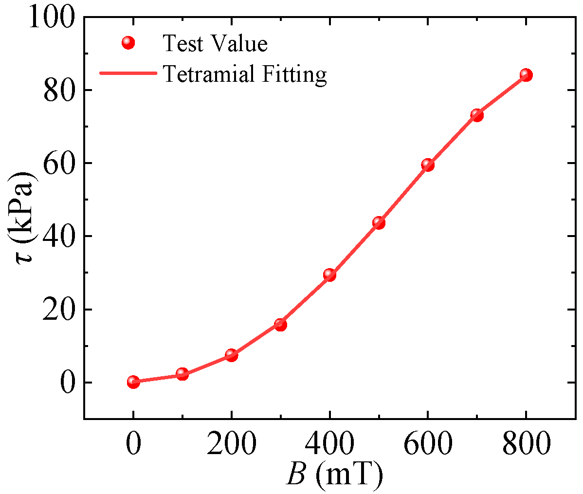
The MRF was selected from the SSCL-LV (Smart Structure Control Laboratory) created in our lab. The composition ratios are as follows, 18.8 wt% of dimethyl silicone oil, 10 wt% of oleic acid, 70 wt% of carbonyl iron powder, and 1.2 wt% of Nano-silicon dioxide. The τ y B connections could be determined using an Anton Para MRC301 rheometer [38]. Moreover, it was fitted using multinomial fitting. Figure 2 depicts the test and fitting findings.
Equation (15) depicts the fitted connection equation:
τ y = 5.20 × 10 13 B 5 1.27 × 10 9 B 4 + 8.85 × 10 7 B 3 5.57 × 10 5 B 2 + 0.02 B + 0.01
where the unit of τ y is kPa and the unit of B is mT.
The liquid flow field can be expressed in mathematical terms by the joint Equations (10), (11) and (14).
(2)
Boundary conditions
The boundary conditions are indispensable for solving fluid problems, and the viscous fluid boundary conditions are as follows (16):
u F = u s u n F = u n s
where uF and unF denote the velocity at a point on the surface of the fluid wall and its velocity component in the normal direction, respectively; us and uns denote the velocity at a point on the surface of the solid wall and its velocity component in the normal direction, respectively.

3.2.2. Gas Flow Field

(1)
Field control equation
Due to the compressibility of the gas and the non-negligible inertia forces. In the finite element simulation analysis, the performance is described according to the Navier-Stokes equation as follows (17).
ρ 1 u 1 t + ρ ( u 1 ) u 1 = p 1 I + μ a i r ( u 1 + ( u 1 ) T ) 2 3 μ a i r ( u 1 ) I + F V ρ 1 t + ( ρ 1 u 1 ) = 0
(2)
Boundary conditions
The gas flow field boundary conditions are as follows (18):
u g = u s u n g = u n s
where ug and ung denote the velocity at a point on the surface of the gas wall and its velocity component in the normal direction, respectively.

3.3. Solid Mechanics Field

(1)
Field control equation
Because the load on the valve head comes from the MRF, the solid mechanic’s analysis of the damper should consider both the stress-strain of the mechanism and the flow of the internal MRF, as well as the interaction between them, and the solution process involves the solution of the fluid domain and the solid domain as well as the data interaction between the two domains, taking into account the gas-flow field coupling. Combined with reference [27], it is known that the multi-body dynamic field equation is (19):
ρ 2 2 d s o i l d t 2 = σ k + F V F s = σ k n f s = n p I + μ ( u 1 + ( u 1 ) T )
where ρ 2 is the solid material density, dsoild is the structural displacement vector, defined as a vector pointing from the original position of a point in a solid structure to its new position, σ k is the quadratic Corsi stress tensor, Fs is the force acting on the solid mechanical domain, n denotes the normal vector at the fluid-solid coupling boundary, and fs is the combined force acting on the fluid-solid coupling boundary.
The Cauchy stress can be calculated using the Piola-Kirchhoff stress (20) as follows:
σ k = J 1 F S p F T
where J is the deformation of the Jacobi matrix; F is the deformation gradient vector, and Sp is the Piola-Kirchhoff stress tensor.
The deformation gradient vector F could be expressed in terms of the gradient of the structural displacement vector solid (21):
F = I + d s o i l s
The Piola-Kirchhoff stress tensor Sp could be derived from the ratio of the strain energy density v ε to the Lagrangian strain tensor ε L (22):
S p = v ε ε L
ε L is calculated from [39]:
ε L = 1 2 ( d s o l i d   ) T + d s o l i d   + ( d s o l i d   ) T d s o l i d  
(2)
Boundary conditions
For the fluid-solid coupling boundary, a no-slip boundary condition is set for it, where the flow velocity ut of the fluid is equal to the structural velocity u2.
u t = u 2 = d s o i l t

4. Multi-Physics Field Coupling Simulation

4.1. Simulation Model Building

Currently, research on the multi-physics simulation of the MRD with compensation mechanisms has neglected the compensation mechanism and established a symmetrical simulation mechanism for simulation. This excessive simplification leads to a significant deviation between the simulation model and reality, and ignores the additional stiffness brought by the compensation cavity to the mechanism. Therefore, this paper establishes a multi-physics coupling simulation model of an MR damper based on a single-rod compensation mechanism, as shown in Figure 3, with the aim of further accurately characterizing its mechanical performance.
The model drives the valve motion to move the MR fluid with the floating valve by giving the valve displacement load; the pressure distribution and flow velocity distribution within the flow field during the motion are calculated and obtained through the setting of the fluid-solid coupling boundary, and the data are transferred to the solid mechanic’s module to further obtain the mechanical properties of the damper including the F-S and additional stiffness curves. Meanwhile, the coil wound on the valve, through the excitation current, the electric field, generates the magnetic induction intensity coupling the magnetic field with the flow field through the defined properties of the MR fluid. Meanwhile, the coil wound on the valve generates a magnetic induction intensity through the excitation current, which couples the magnetic field with the fluid field by defining the characteristics of the MRF. The specific coupling relationship is as follows. Firstly, for the coupling of the electromagnetic field and flow field, the yield strength τ y of MRF changes under the action of magnetic field B. The Bingham viscoelastic model of MRF is established in the simulation, and the results of the electromagnetic field are output to the flow field through multiple physical field interfaces so that the magnetic field is coupled with the flow field. Secondly, the fluid-structure coupling is due to the interaction between the fluid and the solid. The motion u of the damping valve causes the flow of the fluid, and the flow of the fluid generates a pressure drop Δ p , which in turn gives a reaction force to the valve, resulting in a damping force. Among them, the fluid-solid coupling boundary needs to satisfy two boundary conditions:
  • The displacement of the solid and fluid on the coupling boundary is equal d s = d f .
  • The stress at the boundary between solid and fluid is equal n · τ s = n · τ f .
The proposed multi-physics coupling simulation model of the MRD based on a single-rod compensation mechanism can more accurately describe its mechanical performance. It can not only help optimize product design and improve product performance and quality but also reduce experimental costs and time, providing a more effective method for the research of this type of MR damper.
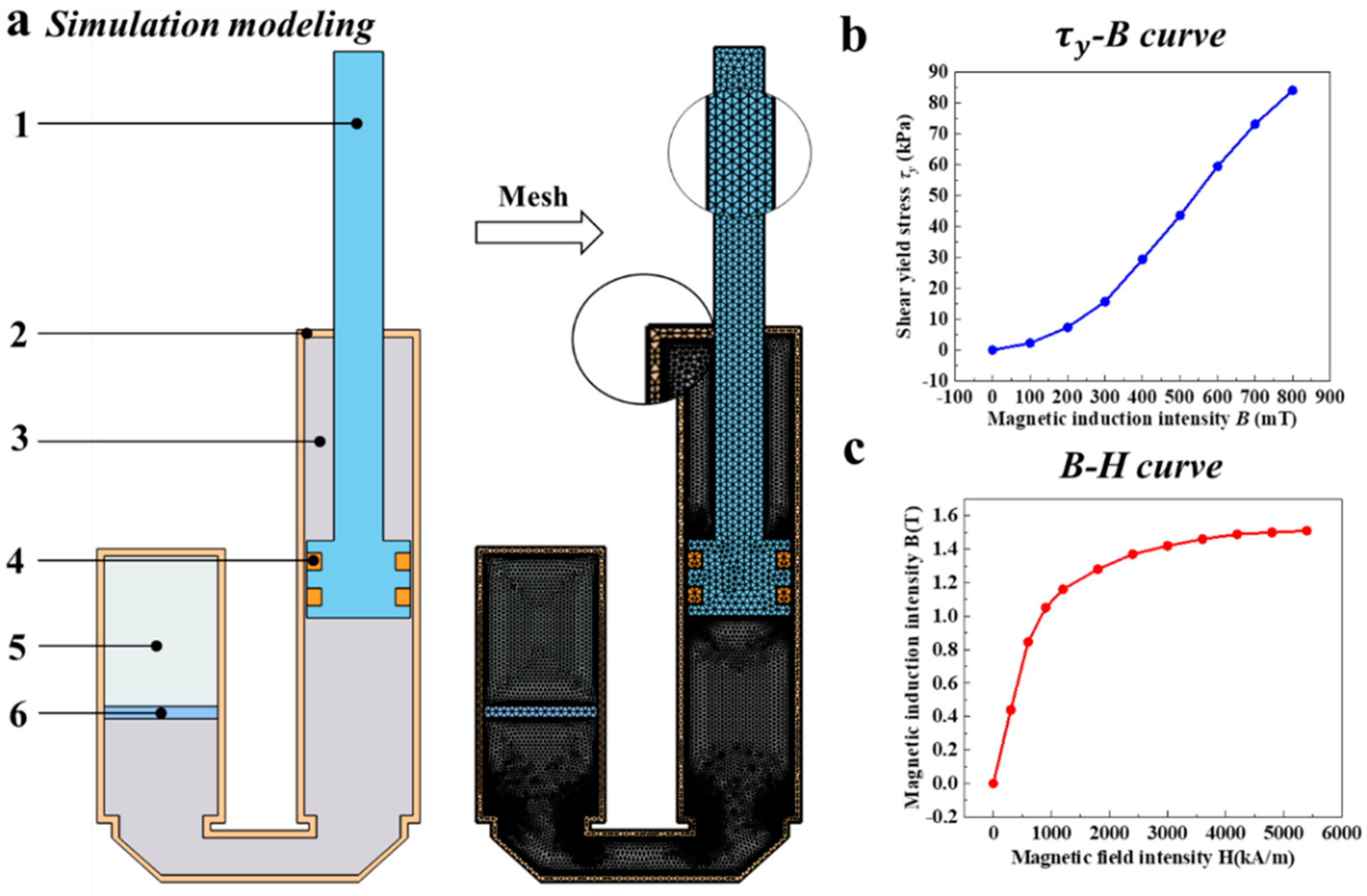
To accurately analyze the mechanical performance of an MRD, a two-dimensional simulation model for analyzing the simulation results of this type of damper was created in COMSOL, as shown in Figure 4a. The model consists of a valve and valve rod, coils, an outer wall, a floating valve, MRF, and air. The appropriate finite element simulation mesh division is crucial for accurately predicting physical behavior, and a free triangular mesh is used to ensure calculation accuracy and computational space. To ensure the accuracy of the fluid part, more layers of mesh are divided at the fluid boundary, and two fluid domains are set as dynamic meshes for fluid dynamic simulation. At the same time, the MRF is defined as a non-Newtonian Bingham model, and the magnetic field and flow field are coupled through this model. During the coupling process, the τ y -B relationship plays a key intermediary role in connecting the magnetic field and the flow field. To better fit the properties of the magnetorheological fluid, a polynomial fitting method is used to fit the B-H relationship and the τ y -B relationship of the magnetorheological fluid, as shown in Figure 4b,c.

4.1.1. Magnetic Field Simulation

The MRD is a control device based on the magneto-rheological effect, and its key component is the magnetic field. The quality of the magnetic field directly affects the performance of the MRD. Therefore, in the design and performance optimization research of the MRD, the analysis and evaluation of the magnetic field are particularly important. In order to improve the control performance of the MRD, this article adopts a double-coil design to increase the effective length of the channel. In the simulation analysis, the dimensions of the coil slot design were estimated and the number of turns of the single coil was determined to be 150. At the same time, based on the maximum driving current of the actual driver, a simulation analysis of the current ranges from 1 to 5 A was conducted. The simulation results are shown in Figure 5.
The simulation results of the flow field indicate that the magnetic field lines originate from the valve, pass through the MRF region and the cylinder wall, and then return to the valve head, forming a closed-loop magnetic circuit. Compared with a single coil, the design of a dual coil increases the magnetic field intensity in the middle of the valve by a factor and extends the effective magnetic field strength in the flow channel, thereby improving the magnetic control performance of the MRD. This result is consistent with the design expectations and validates the superiority of the dual coil design. To better describe the change in magnetic field intensity, this paper selects the centerline of the flow channel as the reference line and quantitatively analyzes its magnetic induction intensity. From the simulation results, it can be seen that within the range of current variation from 1 A to 5 A, the maximum magnetic field in the flow channel changes from 50 mT to 260 mT, and the adjustable ratio reaches 5.4. This result indicates that the magneto-rheological damper can control the magnetic field intensity by changing the current, thereby adjusting the damping force of the damper.

4.1.2. Flow Field Simulation

(1)
MRF flow field
According to Figure 5, the magnetic field is mainly concentrated in the MRF in the damping channel, especially in the area around the valve, which is referred to as the activated zone. In contrast, the other regions are referred to as the inactivated zone. Since the magnitude of the magnetic field is directly related to the shear yield strength of the magnetorheological fluid, the shear yield strength of the MRF close to the valve is higher than that of the other regions.
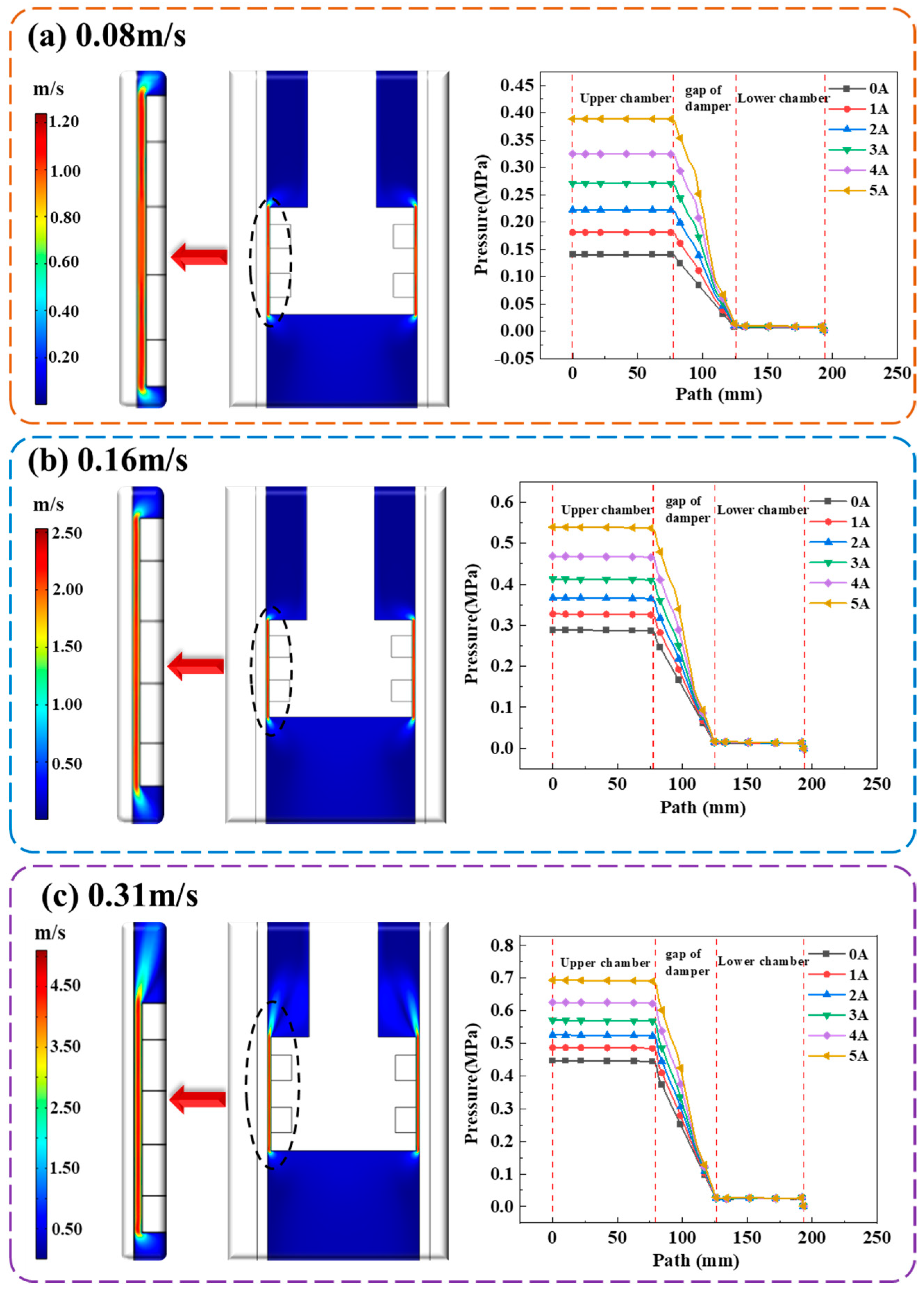
By importing the magnetic induction intensity distribution data into the fluid-mechanism coupling field and combining it with the laboratory’s self-equipped parameters of MR materials, the yield strength distribution of MRF was obtained, and a partial differential equation describing the stress-strain relationship of the MRF was established, considering the apparent viscosity of the fluid. In this system, the cylinder body was fixed, while the valve rod and valve were subjected to sinusoidal displacement excitation. The MRF flowed through the damping channel from the high-pressure area to the low-pressure area, producing a reactive force that hindered the valve’s movement. In Figure 6, the velocity cloud map and pressure map of the MRF flow field under different valve speeds and control current conditions were shown. It could be observed that with the increase of valve speed and current, the fluid velocity in the channel and pressure in the flow field also increase continuously. Based on the qualitative analysis of the simulation results, it can be concluded that the behavior of the system conforms to basic logic and design expectations.
(2)
Gas flow field
Neglecting the compensating force of the compensation gas chamber while evaluating the mechanical performance of a single-rod gas-compensated MRD may result in considerable variations between the simulation model and the actual system. This is because the increased stiffness generated by the compensating mechanism is not considered.
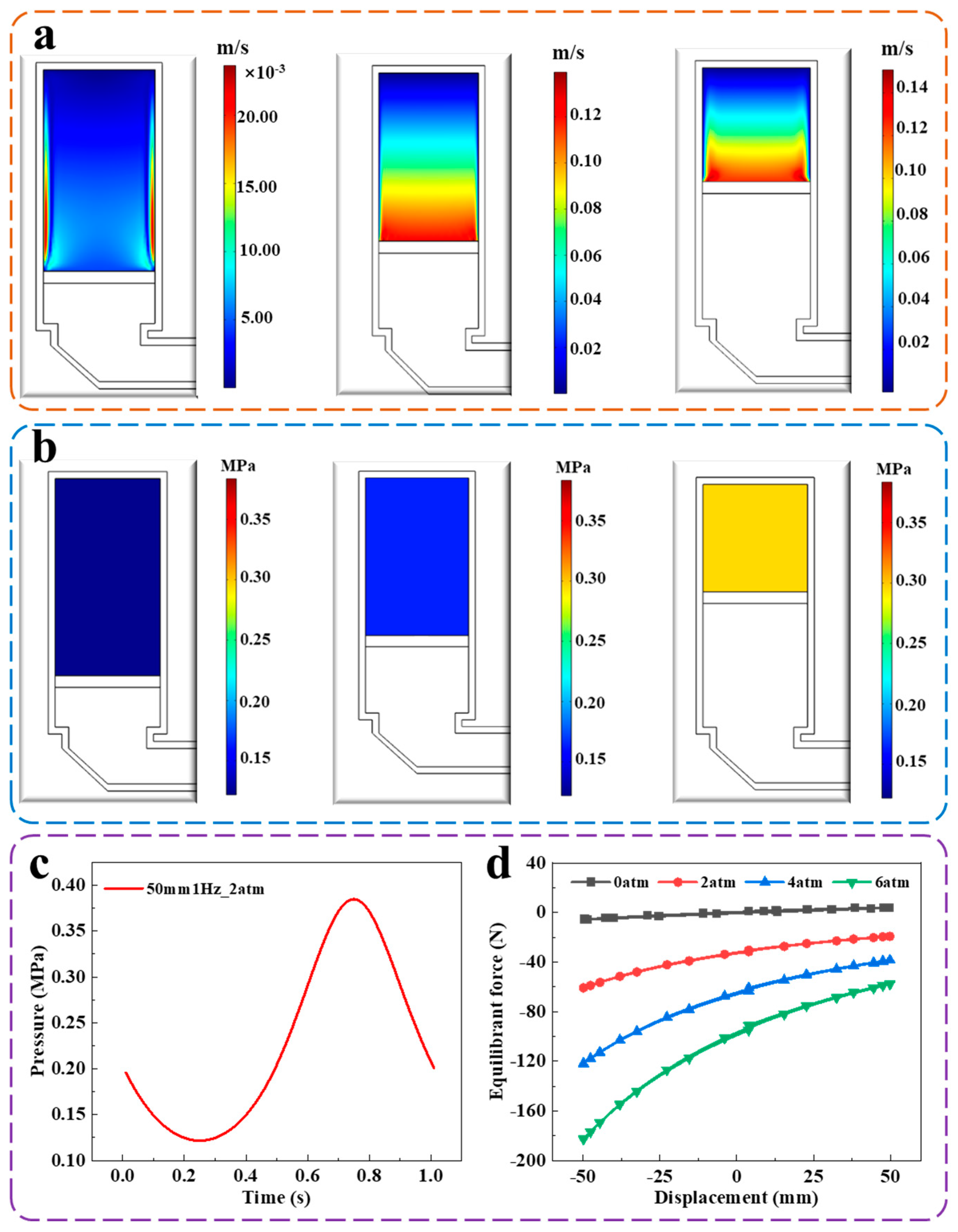
As a result, the influence of the compensation gas chamber’s compensating force on the mechanical performance of the MRD must be considered. A gas flow simulation program for this purpose was presented. The study is based on the basic theory of fluid mechanics and the boundary conditions of fluid-mechanism coupling. The gas flow field part is set as an air domain and set as a compressible fluid, and dynamic mesh is used for simulation. By analyzing the simulation results, velocity and pressure distribution diagrams of the flow field under different operating modes are obtained, as shown in Figure 7a,b. From the figures, it could be seen that as the volume of the compensation gas chamber is compressed, both the flow field velocity and pressure increase continuously. The flow field velocity gradually decreases from the floating valve to the cylinder wall, while the flow field pressure is uniformly distributed in the compensation gas chamber. Qualitative analysis shows that the simulation results conform to the theoretical characteristics. At the same time, quantitative analysis is performed, and it is found that under the operating conditions of the amplitude of 50 mm, frequency of 1 Hz, and compensation gas pressure of 2 atm, its pressure is asymmetric as shown in Figure 7c. The reason is that the compensating gas chamber is in compression for the first half cycle and in tension for the second half cycle. According to the gas ideal Equation (24) and the damper motion relationship from Equation (25), it is known that the different motion directions of the damper cause the asymmetric change of Va, which in turn makes the pressure in the compensating gas cavity appear asymmetric.
p a = p 0 V 0 V a k
where p a is the pressure in the compensating gas chamber during operation. Other parameters are defined in Equation (1).
The Va may be introduced based on the working state of the damper, as shown in Equation (25).
V a = V 0 π d 2 4 x
The direction of motion is different and the positive and negative of x are different.
Figure 7d shows that the compensation force value varies in one cycle under different pressures and increases with the increase of the initial compensation gas pressure. This simulation method helps to understand better the mechanical performance of the MRD and its important role in the compensation gas chamber. The research results have a deep understanding of the mechanical performance of this type of MRD and provide a reference for its design optimization in practical applications.

4.1.3. Solid Force Field Simulation

The equations of motion of the valve head are necessary to model the excited vibration of the dampers and to carry out dynamic simulations to analyze the mechanical characteristics of MRD under the impact of numerous physical fields. Simultaneously, the “work shown” properties of the damper must be configured for varied speeds and control currents at the same compensating air pressure.
The starting air pressure in the compensation chamber is set to 2 atm in the simulation, the valve head travels sinusoidally with an amplitude of 50 mm and velocities of 0.08 m/s, 0.16 m/s, and 0.31 m/s, and the excitation current is set to 0/1/3/5 A. Figure 8a depicts the simulation findings. During motion, the compensating air chamber provides a certain amount of compensation stiffness, which makes the damping F-S curve appear as a full “back” shape, and the displacement ring is not strictly symmetrical about the x-axis, but has a certain tilt, the larger the angle of tilt, the greater the additional stiffness of the system. It is worth noting that the additional stiffness is only speed-dependent and is not controlled by the current (the slope of the power curve is the same for different currents at the same speed). This is because the additional stiffness is not controlled by the current and is provided entirely by the compensating cavity.
In the simulation, it was also necessary to investigate the effect of different initial air pressures on the dynamic performance of the MRD. The dynamic simulations were carried out by setting the excitation current to a constant 1 A, given different initial air pressures in the valve head and a sinusoidal excitation with different velocities. From the simulation results in Figure 8b, it could be found that the additional stiffness increases with increasing initial air pressure at the same speed. Equation (1) shows that the F η increases as the valve velocity increases, but the F g a s is not affected by the velocity. Therefore, at low speeds, the F-S curve will show a significant slope because the F g a s accounts for a relatively large amount. Moreover at high speeds, it becomes less influential on the output damping force as the F g a s accounts for a lower percentage. Therefore, the additional stiffness has less and less influence on it.
It can be visualized from the diagram that the MRD have great magneto-control properties, especially at low speeds. In addition, the multi-physical field-coupled simulation system built could visualize the mechanical properties of the MRD with a compensation mechanism under different operating conditions. In particular, the additional stiffness characteristics have often been neglected in previous simulations.

5. Experimental Testing and Verification

5.1. Experimental Tests

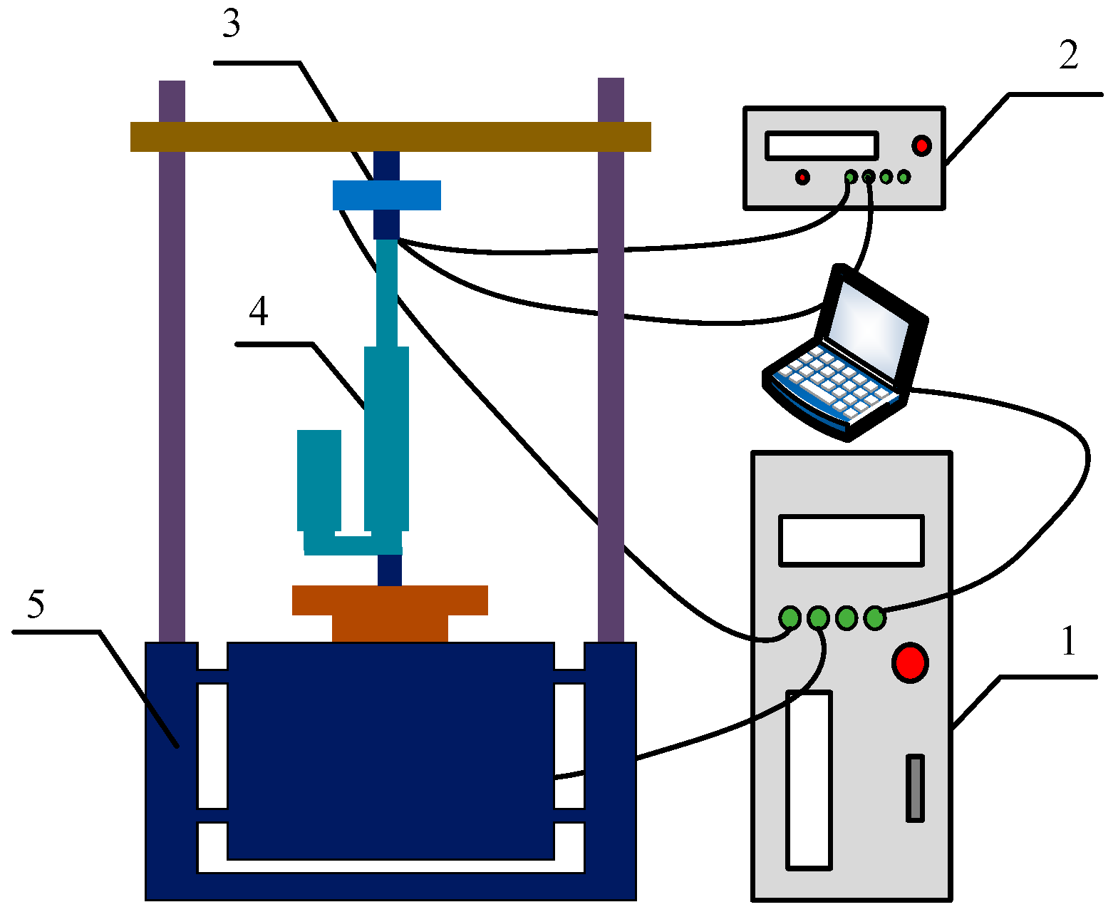
In order to verify the accuracy of the Multiphysics simulation, a physical model of a MRD was made and tested using an experimental system (shown in Figure 9).
During the testing process, a working dynamometer Mechanical Test & Simulation (WDTS) vibration testing platform was used to provide excitation, and mechanical characteristic data were collected at different speeds (0.08 m/s, 0.16 m/s, and 0.31 m/s), different currents (0 A, 1 A, 3 A, and 5 A), and different pressures (2 atm and 4 atm). At the same time, an Agilent DC power supply (8032 A) was used to provide voltage/current, and the temperature was kept constant at 25 ± 2 °C.

5.2. Experimental Verification

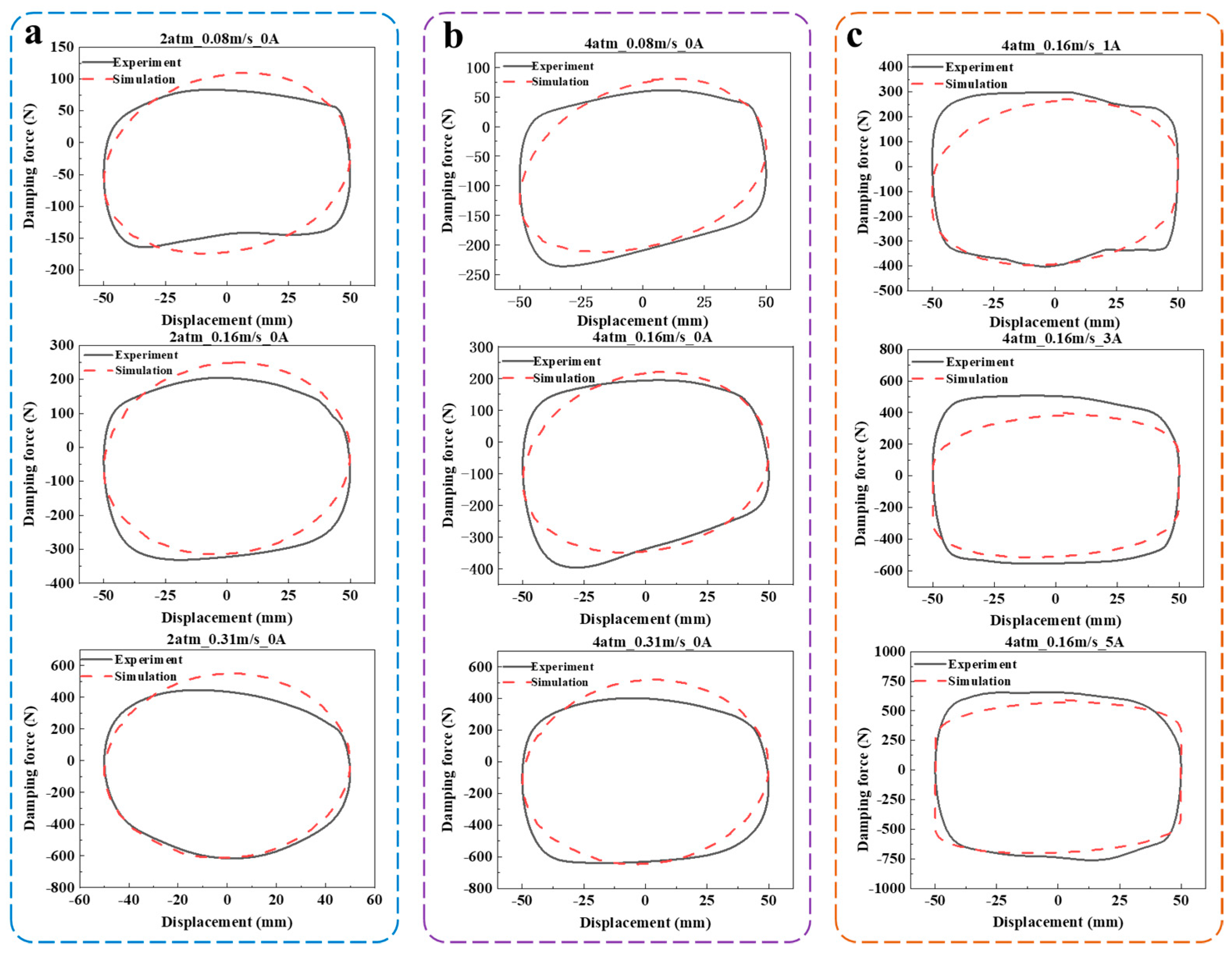
The results in Figure 10 compare the simulated and experimental hysteresis curves of the damper under different current, velocity, and initial pressure compensation conditions. Panel (a) shows the comparison of the experimental and simulated hysteresis curves at a 0 A current and different velocities, with an initial compensation pressure of 2 atm. Panel (b) shows the comparison of the hysteresis curves at a 0 A current and different velocities, with an initial pressure of 4 atm. Panel (c) shows the comparison of the hysteresis curves at a velocity of 0.16 m/s and different currents, with an initial pressure of 4 atm. Qualitatively, the simulation results could represent the experimental results under different operating conditions, and could accurately describe the additional stiffness characteristics of this type of MRD. Therefore, the simulation results are of certain reference value.
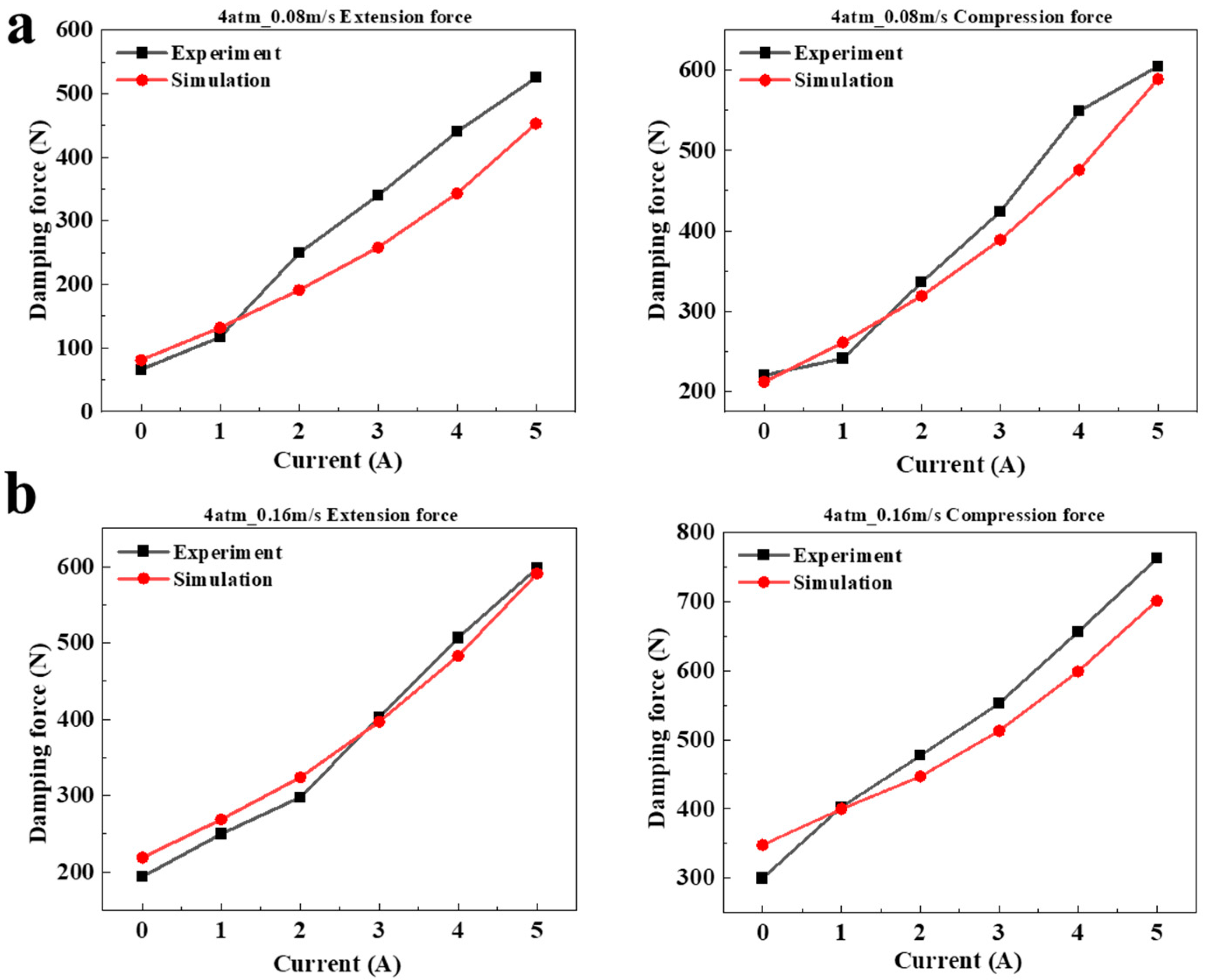
Quantitatively, Figure 11 and Table 2 demonstrate the errors between the tested and simulated damping forces at the 0-displacement point under different operating conditions. The results show that the error of the extension force is relatively large at a velocity of 0.08 m/s, with a maximum error of 24.1%, while most errors remain within 10%. This phenomenon may be caused by the following two aspects. First, Equation (1) shows that the damping force is smaller at a low speed and the base of the relative error of calculation is also smaller, which leads to a more significant relative error of the damping force at low speed and less relative error of the damping force at high speed. Especially in the extension stage, the gas expansion movement may cause a hysteresis effect in the compensation force during actual work. Secondly, the dampers may have certain assembly errors and be affected by environmental factors, which can lead to certain absolute errors between the experiment and simulation results. Overall, the relative errors are below 25%, with the minimum being 0.7%, which is within an acceptable range and directly verifies the accuracy of the multi-physics coupling simulation. The reasons for the errors also may be that the effect of gravity was not considered in the multi-physics simulation, or there were certain experimental deviations during the actual testing process, which needs further exploration.

6. Conclusions

A 2D full model of a single-rod compensating pneumatic MRD was established, and a corresponding damper damping force model was derived to address the issue of additional stiffness and force values. Existing Multiphysics simulation models were unable to describe this problem accurately.
(1)
The simulation model was built based on the non-Newtonian constitutive relationship of the MRF, and the coupling analysis of the three fields utilized COMSOL. The simulation results showed the feasibility of the damper simulation system, including the magnetic field characteristics, MRF liquid flow characteristics, compensating mechanism of gas flow characteristics, and the damper dynamic mechanical diagram under the coupling action of multiple physical fields.
(2)
The damping force was experimentally tested, and the F-S curves were compared under different excitation conditions, with error analysis conducted. The experimental and simulation results had a high degree of coincidence, with a maximum error of 24.1% and a minimum error of only 0.7% for the damping force under different currents. The accuracy of the Multiphysics coupling simulation was further verified. The average error between experimental value and simulation value is 7%.
(3)
As the maximum error between the experiment and simulation was 24.1%, further analysis was necessary to determine the cause and improve the accuracy of the experiment and simulation.
This study allows a more accurate prediction of the mechanical properties of MRD with a compensating mechanism, in particular the description of the additional stiffness, without the need for extensive physical experiments, which thus reduces the development costs. In addition, it is of academic and practical value as a guide to the design and application of it.

Author Contributions

Conceptualization, H.L.; Methodology, H.L. and J.F.; Software, J.L.; Validation, J.L. and M.L.; Investigation, Y.W.; Writing—original draft, H.L.; Writing—review & editing, J.F., L.L. and M.Y.; Supervision, M.Y.; Funding acquisition, J.F. and M.Y. All authors have read and agreed to the published version of the manuscript.

Funding

This research was supported by the National Natural Science Foundation of China (Grant No. 51875056). The authors are grateful for the helpful comments from the reviewers and editor to improve the paper.

Data Availability Statement

All data that support the findings of this study are included within the article (and any supplementary files).

Conflicts of Interest

The authors declare no conflict of interest.

References

  1. Deng, X.; Pan, Z.W.; Xing, J.W.; Zhang, Z.Y.; Li, Y.X.; Yan, M.S.; Dong, X.M. Controllability analysis and intelligent control of magnetorheological whole-satellite under small amplitude and medium-high frequency vibration. J. Intell. Mater. Syst. Struct. 2023, 34, 229–248. [Google Scholar] [CrossRef]
  2. Dong, L.; Chen, Z.Q.; Sun, M.W.; Sun, Q.L. Phase compensation active disturbance rejection control for shimmy vibration with magnetorheological damper of aircraft. Expert Syst. Appl. 2023, 213, 119126. [Google Scholar] [CrossRef]
  3. Deng, Z.X.; Wei, X.X.; Li, X.Q.; Zhao, S.E.; Zhu, S.K. Design and multi-objective optimization of magnetorheological damper considering vehicle riding comfort and operation stability. J. Intell. Mater. Syst. Struct. 2021, 33, 1215–1228. [Google Scholar] [CrossRef]
  4. Marathe, A.P.; Khot, S.M.; Nagler, J. Development of low-cost optimal magneto-rheological damper for automotive application. J. Vib. Eng. Technol. 2022, 10, 1831–1850. [Google Scholar] [CrossRef]
  5. Du, X.M.; Han, G.W.; Yu, M.; Peng, Y.X.; Xu, X.Y.; Fu, J. Fault detection and fault tolerant control of vehicle semi-active suspension system with magneto-rheological damper. Smart Mater. Struct. 2021, 30, 014004. [Google Scholar] [CrossRef]
  6. Hou, S.; Liu, G. Research on Theoretical Modeling and Parameter Sensitivity of a Single-Rod Double-Cylinder and Double-Coil Magnetorheological Damper. Math. Probl. Eng. 2020, 2020, 5489896. [Google Scholar] [CrossRef] [Green Version]
  7. Xiao, W.; Fei, C.; Aimin, L.; Nana, S. Research on the Performance of a Novel Magnetorheological Damper for Mining. J. Vib. Eng. Technol. 2023. [Google Scholar] [CrossRef]
  8. Abdeddaim, M.; Djerouni, S.; Ounis, A.; Athamnia, B.; Noroozinejad Farsangi, E. Optimal design of magnetorheological damper for seismic response reduction of Base-Isolated structures considering Soil-Structure interaction. Structures 2022, 38, 733–752. [Google Scholar] [CrossRef]
  9. Şahin, Ö.; Gökhan Adar, N.; Kemerli, M.; Çaglar, N.; Şahin, İ.; Parlak, Z.; Kükrek, S.; Engin, T. A comparative evaluation of semi-active control algorithms for real-time seismic protection of buildings via magnetorheological fluid dampers. J. Build. Eng. 2021, 42, 102795. [Google Scholar] [CrossRef]
  10. Tell, S.; Andersson, A.; Najafi, A.; Spencer, B.F.; Karoumi, R. Real-time hybrid testing for efficiency assessment of magnetorheological dampers to mitigate train-induced vibrations in bridges. Int. J. Rail Transp. 2021, 10, 436–455. [Google Scholar] [CrossRef]
  11. Xu, Z.D.; Xu, Y.W.; Wang, C.; Zhao, Y.L.; Ji, B.H.; Du, Y.L. Force tracking model and experimental verification on a novel magnetorheological damper with combined compensator for stay cables of bridge. Structures 2021, 32, 1971–1985. [Google Scholar] [CrossRef]
  12. Kanarachos, S.; Savitski, D.; Lagaros, N.; Fitzpatrick, M.E. Automotive magnetorheological dampers: Modelling and parameter identification using contrast-based fruit fly optimisation. Soft Comput. 2017, 22, 8131–8149. [Google Scholar] [CrossRef]
  13. Kim, B.-G.; Yoon, D.-S.; Kim, G.-W.; Choi, S.-B.; Tan, A.S.; Sattel, T. Design of a Novel Magnetorheological Damper Adaptable to Low and High Stroke Velocity of Vehicle Suspension System. Appl. Sci. 2020, 10, 5586. [Google Scholar] [CrossRef]
  14. Song, X.Y.; Dong, X.M.; Yan, M.S.; Li, X. Investigation of an Automobile magnetorheological damper with asymmetric mechanical characteristics. J. Phys. Conf. Ser. 2020, 1678, 012012. [Google Scholar] [CrossRef]
  15. Guo, D.L.; Hu, H.Y. Nonlinear stiffness of a magneto-rheological damper. Nonlinear Dyn. 2005, 40, 241–249. [Google Scholar] [CrossRef]
  16. Graczykowski, C.; Pawłowski, P. Exact physical model of magnetorheological damper. Appl. Math. Model. 2017, 47, 400–424. [Google Scholar] [CrossRef]
  17. Sun, M.; Li, X.; Zhou, Z.; Zhu, Q.; Liu, B.; Chen, X.; Wang, J.; Zhang, G.; Cai, S. Analysis of Damping Characteristics of Magnetorheological Damper under Impact Load. Materials 2022, 15, 4161. [Google Scholar] [CrossRef] [PubMed]
  18. Tu, J.; Li, Z.; Zhang, J.; Gao, K.; Liao, J.; Gao, J. Development, Test, and Mechanical Model of the Leak-Proof Magnetorheological Damper. Front. Mater. 2019, 6, 118. [Google Scholar] [CrossRef] [Green Version]
  19. Elsaady, W.; Oyadiji, S.O.; Nasser, A. Magnetic Circuit Analysis and Fluid Flow Modelling of an MR Damper with Enhanced Magnetic Characteristics. IEEE Trans. Magn. 2020, 56, 4600420. [Google Scholar] [CrossRef]
  20. Jian, Y.; Longlei, D. Design and modeling of a magnetorheological damper with double annular damping gap. J. Intell. Mater. Syst. Struct. 2022, 34, 976–989. [Google Scholar] [CrossRef]
  21. Palomares, E.; Morales, A.L.; Nieto, A.J.; Chicharro, J.M.; Pintado, P. Modelling Magnetorheological Dampers in Preyield and Postyield Regions. Shock Vib. 2019, 2019, 5636053. [Google Scholar] [CrossRef] [Green Version]
  22. Pei, P.; Peng, Y.; Qiu, C. Magnetorheological damper modeling based on a refined constitutive model for MR fluids. J. Intell. Mater. Syst. Struct. 2021, 33, 1271–1291. [Google Scholar] [CrossRef]
  23. Xu, F.H.; Dong, D.W.; Huang, Y.; Song, S.; Yan, B. Physical modeling and experimental verification of magneto-rheological damper under medium and high frequency excitation. Proc. Inst. Mech. Eng. Part L J. Mater. Des. Appl. 2020, 235, 353–365. [Google Scholar] [CrossRef]
  24. Sternberg, A.; Zemp, R.; de la Llera, J.C. Multiphysics behavior of a magneto-rheological damper and experimental validation. Eng. Struct. 2014, 69, 194–205. [Google Scholar] [CrossRef]
  25. Gurubasavaraju, T.M.; Kumar, H.; Mahalingam, A. An approach for characterizing twin-tube shear-mode magnetorheological damper through coupled FE and CFD analysis. J. Braz. Soc. Mech. Sci. Eng. Struct. 2018, 40, 139. [Google Scholar] [CrossRef]
  26. Hu, G.L.; Wu, L.F.; Deng, Y.J.; Yu, L.F.; Luo, B. Damping Performance Analysis of Magnetorheological Damper Based on Multiphysics Coupling. Actuators 2021, 10, 176. [Google Scholar] [CrossRef]
  27. Hu, G.L.; Wu, L.F.; Deng, Y.J.; Yu, L.F.; Li, G. Optimal design and performance analysis of magnetorheological damper based on multiphysics coupling model. J. Magn. Magn. Mater. 2022, 558, 169527. [Google Scholar] [CrossRef]
  28. Nie, S.L.; Xin, D.K.; Ji, H.; Yin, F.L. Optimization and performance analysis of magnetorheological fluid damper considering different piston configurations. J. Intell. Mater. Syst. Struct. 2019, 30, 764–777. [Google Scholar] [CrossRef]
  29. Liu, G.; Gao, F.; Liao, W.-H. Magnetorheological damper with multi-grooves on piston for damping force enhancement. Smart Mater. Struct. 2020, 30, 025007. [Google Scholar] [CrossRef]
  30. Zhang, G.; Wang, H.X.; Qing, O.Y.; Wang, J. Numerical analysis of multiphysical field for independent three-stage magnetorheological damper of double rod during recoil process of artillery. Proc. Inst. Mech. Eng. Part C J. Mech. Eng. Sci. 2019, 233, 4960–4979. [Google Scholar] [CrossRef]
  31. Zheng, J.J.; Li, Y.C.; Wang, J. Design and multi-physics optimization of a novel magnetorheological damper with a variable resistance gap. Proc. Inst. Mech. Eng. Part C-J. Mech. Eng. Sci. 2017, 231, 3152–3168. [Google Scholar] [CrossRef]
  32. Zheng, J.J.; Li, Z.C.; Koo, J.; Wang, J. Magnetic Circuit Design and Multiphysics Analysis of a Novel MR Damper for Applications under High Velocity. Adv. Mech. Eng. 2014, 6, 402501. [Google Scholar] [CrossRef] [Green Version]
  33. Yuan, X.J.; Qiu, T.Y.; Tian, T.Y. Design and modelling methodology for a new magnetorheological damper featuring a multi-stage circumferential flow mode. Int. J. Mech. Mater. Des. 2022, 18, 785–806. [Google Scholar] [CrossRef]
  34. Hu, G.; Long, M.; Huang, M.; Li, W. Design, Analysis, Prototyping, and Experimental Evaluation of an Efficient Double Coil Magnetorheological Valve. Adv. Mech. Eng. 2014, 6, 403410. [Google Scholar] [CrossRef] [Green Version]
  35. Hu, W.; Wereley, N.M. Hybrid magnetorheological fluid–elastomeric lag dampers for helicopter stability augmentation. Smart Mater. Struct. 2008, 17, 045021. [Google Scholar] [CrossRef]
  36. Susan-Resiga, D. A Rheological Model for Magneto-rheological Fluids. J. Intell. Mater. Syst. Struct. 2009, 20, 1001–1010. [Google Scholar] [CrossRef]
  37. Min, J.; Xiaoting, R.; Fufeng, Y.; Wei, Z.; Hongtao, Z.; Wenjiao, H. Design and dynamic performance research of MR hydro-pneumatic spring based on multi-physics coupling model. Nonlinear Dyn. 2023, 111, 8191–8215. [Google Scholar] [CrossRef]
  38. Li, S.; Yu, M.; Liu, J.; Fu, J.; Gan, R.; Li, Y.; Yao, H.; Qi, S. Attenuation of magneto-induced yield stress by magnetic carrier liquid in magnetorheological fluids. Appl. Phys. Lett. 2022, 121, 162901. [Google Scholar] [CrossRef]
  39. Takaddus, A.T.; Chandy, A.J. A three-dimensional (3D) two-way coupled fluid-structure interaction (FSI) study of peristaltic flow in obstructed ureters. Int. J. Numer. Methods Biomed. Eng. 2018, 34, e3122. [Google Scholar] [CrossRef]
Figure 1. Mechanism diagram of a single-rod gas-compensated MRD. 1—Lifting ring; 2—Valve rod; 3—Head cap; 4—Oil seal; 5—Guide ring; 6—Cylinder barrel; 7—Valve outer barrel; 8—Coil; 9—Magnetic induction line; 10—compensating air chamber; 11—Floating valve; 12—Base.
Actuators 12 00251 g001
Figure 2. B curve of SSCL-LV MRF.
Actuators 12 00251 g002
Figure 3. Multi-physical field coupling simulation diagram of a single-rod gas compensated MRD.
Actuators 12 00251 g003
Figure 4. Simulation model of MRD. (a) The simulation model and meshing diagram; (b) τ y -B curve; (c) B-H curve.
Actuators 12 00251 g004
Figure 5. Electromagnetic field simulation results. (a) Cloud map of the magnetic field distribution under different currents; (b) Distribution of the magnetic induction intensity in the channel.
Actuators 12 00251 g005
Figure 6. MRD fluid force field simulation results. (a) 0.08 m/s flow field velocity and pressure changes; (b) 0.16 m/s flow field velocity and pressure changes; (c) 0.31 m/s flow field velocity and pressure changes.
Actuators 12 00251 g006
Figure 7. Simulation result of compensated gas chamber fluid force field. (a) Velocity distribution; (b) Pressure distribution; (c) Pressure change in a period; (d) Change of compensating force under different initial pressure.
Actuators 12 00251 g007
Figure 8. Solid force field simulation results. (a) 2 atm F-S curve of different speed and current; (b) 1 A F-S curve of different initial pressure and speed.
Actuators 12 00251 g008
Figure 9. MRD performance experimental system. 1—Operations Station; 2—DC Power Supply; 3—Force Sensor; 4—MRD; 5—WDTS.
Actuators 12 00251 g009
Figure 10. Comparison of simulation and experiment F-S curves. (a) Comparison of 2 atm–0 A F-S with different speeds; (b) Comparison of 4 atm–0 A F-S with different speeds; (c) Comparison of 4 atm–0.16 m/s F-S with different currents.
Actuators 12 00251 g010
Figure 11. Comparison of damping force between experiment and simulation value at position 0 mm. (a) 0.08 m/s; (b) 0.16 m/s.
Actuators 12 00251 g011
Table 1. MRD mechanism parameter.
ParametersValue (mm)ParametersValue (mm)
Valve rod length 233Compensating cylinder length103
Valve diameter/D144Valve rod diameter/d15
Valve radius/r220Floating valve diameter46
Valve length/L38.4Channel gap/h1
Iron core radius/r013Outer cylinder thickness/h11.75
Table 2. Relative error between experimental and simulated values.
Velocity (m/s)0 A1 A2 A3 A4 A5 A
Extension/0.08−22.7%−12.8%23.3%24.1%22.1%13.7%
Compression/0.083.6%−8.3%5.1%8.3%13.3%1.2%
Extension/0.16−12.9%−7.6%−8.7%1.5%4.7%1.2%
Compression/0.16−16.0%0.7%6.3%7.2%8.7%8.0%
Disclaimer/Publisher’s Note: The statements, opinions and data contained in all publications are solely those of the individual author(s) and contributor(s) and not of MDPI and/or the editor(s). MDPI and/or the editor(s) disclaim responsibility for any injury to people or property resulting from any ideas, methods, instructions or products referred to in the content.