Article

Plasma Actuators for Cycloidal Rotor Thrust Vectoring Enhancement in Airships

by
Amine Benmoussa
*,
Frederico F. Rodrigues
* and
José C. Páscoa
Centre for Mechanical and Aerospace Science and Technologies (C-MAST), Universidade da Beira Interior, Rua Marquês D’Ávila e Bolama, 6201-001 Covilhã, Portugal
*
Authors to whom correspondence should be addressed.
Actuators 2023, 12(12), 436; https://doi.org/10.3390/act12120436
Submission received: 9 October 2023 / Revised: 21 November 2023 / Accepted: 22 November 2023 / Published: 24 November 2023
(This article belongs to the Section Aircraft Actuators)

Abstract

:
Airships are a method of transportation with reduced fuel consumption and great potential for different applications. However, these aerial vehicles still present considerable control and maneuverability problems. To overcome these issues, in the current work, we propose the use of plasma-enhanced cycloidal rotor thrusters to increase the controllability and maneuverability of airships. Numerical simulations are carried out to demonstrate the potential of plasma actuators to enhance the efficiency and thrust vectoring capabilities of cycloidal rotors. The fluid dynamics of the flow effects created via the operation of the cycloidal rotor is analyzed with and without plasma actuation. In addition, smart combined plasma actuation is proposed to further optimize the plasma-coupled cycloidal rotor device. The results demonstrated that by using this novel approach, the lift coefficient was increased by about 27%. To summarize, the obtained results for a rotational speed of 100 rpm are compared with results for 200 rpm, and it is demonstrated that for lower rotational speeds, the plasma effect is increased and more significant. This allows us to conclude that airships are an ideal application for plasma-enhanced cycloidal rotors, because since the lift is mostly generated via aerostatic principles, the plasma-enhanced thruster can be operated at lower rotational speeds and effectively increase the controllability and maneuverability of the aerial vehicle.

1. Introduction

Airships are aerial vehicles with great potential for a wide variety of applications, including heavy cargo transportation, environmental monitoring, civil communications, emergency rescue, scientific exploration, observation, real-time surveillance, or space-transferring platforms [1,2]. This type of aerial vehicle has received increased attention because it makes use of aerostatic principles to achieve considerable fuel consumption reduction comparatively to that achieved by heavier-than-air vehicles [3]. Under the MAAT (Multibody Advanced Airship for Transport) project, several European researchers and institutions worked on developing a cruiser/feeder airship system which would enable a connection between the larger populated centers of the world [4]. This project demonstrated the potential of airships for long permanence at high altitudes and the middle- and long-range transport of passengers and goods as a sustainable and low-pollution means of transportation [5,6]. Since this type of aerial vehicle still presents some control problems, such as near-instant changes in the thrust vector, a lack of maneuver capabilities, self-docking, or a downward vector during cargo offloading, different researcher groups started to study the implementation of cycloidal rotors in airships to overcome these issues [7,8,9,10].
Cycloidal rotors are fluid propulsive devices constituting several oscillating blades which rotate around an axis perpendicular to the travelling direction. These devices present several interesting advantages when compared to conventional propellers. Additionally, they function as electric propulsion, providing benefits for Unmanned Aerial Vehicles (UAVs) [11]. Contrasting the conventional helicopter rotor, the blades of a cyclorotor operate at a uniform speed along their span, which allows the achievement of the best aerodynamic efficiency from each blade [12]. In fact, studies have shown that these propulsive systems can generate higher thrust per power unit than conventional screw propellers can when operating under a similar disk load [13]. In addition, by changing the pitching angle of the blades and controlling the rotational speed, the propulsive jet can be instantaneously controlled in terms of magnitude and direction, providing higher maneuverability and controllability to the aircraft [14]. Moreover, since cycloidal rotors operate at much lower rotational speeds than conventional propellers do, they produce considerably lower levels of noise [12,15].
These propulsive devices were initially introduced in 1926 as a result of the collaboration between the researcher Fredric Kirsten and the Boeing group, which was at this time designated to Kirsten–Boeing propellers [16]. The emergence of this new technology led to the development of several works [17,18,19]; however, after 1940, the research on this new type of propulsion system was somehow abandoned for almost 50 years [20]. The main reason for that was the lack of advanced technologies for the optimization of the control of these devices and, also, the poor analytical methods used to study the cycloidal rotor thruster, which was uncapable of capturing the complex flow phenomena produced via their operation [21]. In the late nineties, with the advance of existent technologies and improvement in computational power and codes, this innovative propulsion system started to grab the attention of several research groups again. The research group of the BOSCH Aerospace incorporation used new methods and knowledge to build and test the efficiency of an unmanned aerial vehicle (UAV) based on cycloidal rotor thrusters [7,22]. These works were followed by studies performed by Onda et al. [8,9,10], who focused on the use of cycloidal rotors for airships, and Hwang et al. [12,23,24], who studied and developed a four-rotor cyclocopter. Meanwhile, Benedict et al. [14,25,26] performed several works with the aim of applying cycloidal rotors for micro-air vehicles (MAV). At this time, a European consortium, under the project CROP (Cycloidal Rotor Optimized for Propulsion), developed several works which allowed the undertaking of various important conclusions regarding the use of cycloidal rotors in commercial aircrafts. Under this project, various works were performed, including analytical studies [27,28], numerical simulations [13,29,30] and experimental tests [31], and demonstrated that cycloidal rotors can be integrated with helicopters, allowing an increase in efficiency to about 60%, or with wings, allowing an efficiency increase of about 40% [32]. In a follow-up of this project, Habibnia and Pascoa [33,34,35] numerically studied the operation of cycloidal rotors under diverse conditions and altitudes, and demonstrated the possibility of optimizing these devices by implementing artificial neural network algorithms.
In order to optimize the performance of cycloidal rotors at different flight operations, in our previous work, we proposed the implementation of dielectric barrier discharge (DBD) plasma actuators for boundary layer flow control on the blades [36,37]. Plasma actuators are very promising devices that only started to be studied for flow control purposes at the end of the last century with the works of Liu and Roth [38] and Roth et al. [39]. In the following years, several researchers focused on the study and analysis of these devices, motivated by appealing features such as their very light weight, instant response, simple fabrication, easy implementation even in curved surfaces, and ability be activated/deactivated using pure electronical means [40,41]. Various studies have been performed since then to understand the influence of dielectric thickness and electrode structure [42], and the influence of the applied voltage signal [43,44], to estimate the plasma force produced [45], to propose new configurations [46,47] and new dielectric materials [48,49] or to increase the durability of the device [50]. The studies performed have focused on different applications and have proven the potential of plasma actuators for separation control [51], transitional flow control [52], wake control [53], airfoil tip gap forcing [54], flow modification based on harmonic forcing [55,56,57], noise reduction [58], improvement in vectorized thrusters’ efficiency [59], or the enhancement of wind power production [60]. Recently, a few authors have also demonstrated that the potential of plasma actuators is not limited to flow control applications by proving that these devices generate considerable thermal effects that can be used for ice mitigation applications [61,62]. Moreover, since they present capacitor behavior, authors demonstrated that they can be used as a capacitive sensor for smart ice detection and mitigation [63,64].
Considering the potential of plasma actuators for flow control, in the current work, we propose the use of these innovative electronic devices for the optimization of cyclorotor thrust vectoring in airships. Numerical simulations are performed with and without plasma actuators for flow control in cycloidal rotors operating at 100 rpm, and these results will be compared with those of the operation of cycloidal thrusters at 200 rpm. The results demonstrate that the plasma flow control effect is increased when the cycloidal thrusters work at a lower rpm. Since for improving the control and maneuverability of airships we do not need high rotational speeds, we conclude that this is the ideal application for plasma-enhanced cycloidal thrusters.

2. Numerical Modeling

2.1. Cycloidal Rotor Test Case

A cyclorotor system is characterized by a rotating-wing apparatus consisting of multiple pitching blades that pivot around an axis aligned with the blade’s span. This mechanical configuration enables the adjustment of the blade pitch angle over a rotation cycle [65]. Manipulating the eccentricity, phase angle, and magnitude of the system offers the unique ability to dynamically alter both the magnitude and direction of the thrust vector. This distinctive ability provides these aspects great potential to eliminate the control and maneuverability problems of airships. The motion of the cyclorotor blades is determined by the dimensions of the mechanical system, and the changes in this motion depend on the control settings of the mechanical system. Each section of the rotor blade operates in accordance with Equation (1), which defines the blade pitch angle variation, θ, through a four-bar linkage mechanism, as depicted in Figure 1.
This variation in the blade pitch angle, θ, is achieved as follows:
θ = π 2 s i n 1 e a cos Ψ + ε c o s 1 a 2 + d 2 L 2 2 a d
where e is the magnitude of eccentricity, Ψ is the azimuth angle, L is the control rod length, ε is the phase angle, and d is the control rod distance. The rotor dimensions are shown in Table 1.
The distance, a , between the eccentricity point and the pivot point is given by the following:
a = e 2 + R 2 2 R e c o s Ψ + ε + π 2
In turn, the blade’s angular pitch speed, ω , is given by the following:
ω = d θ d Ψ Ω
where Ω denotes the rotational speed.
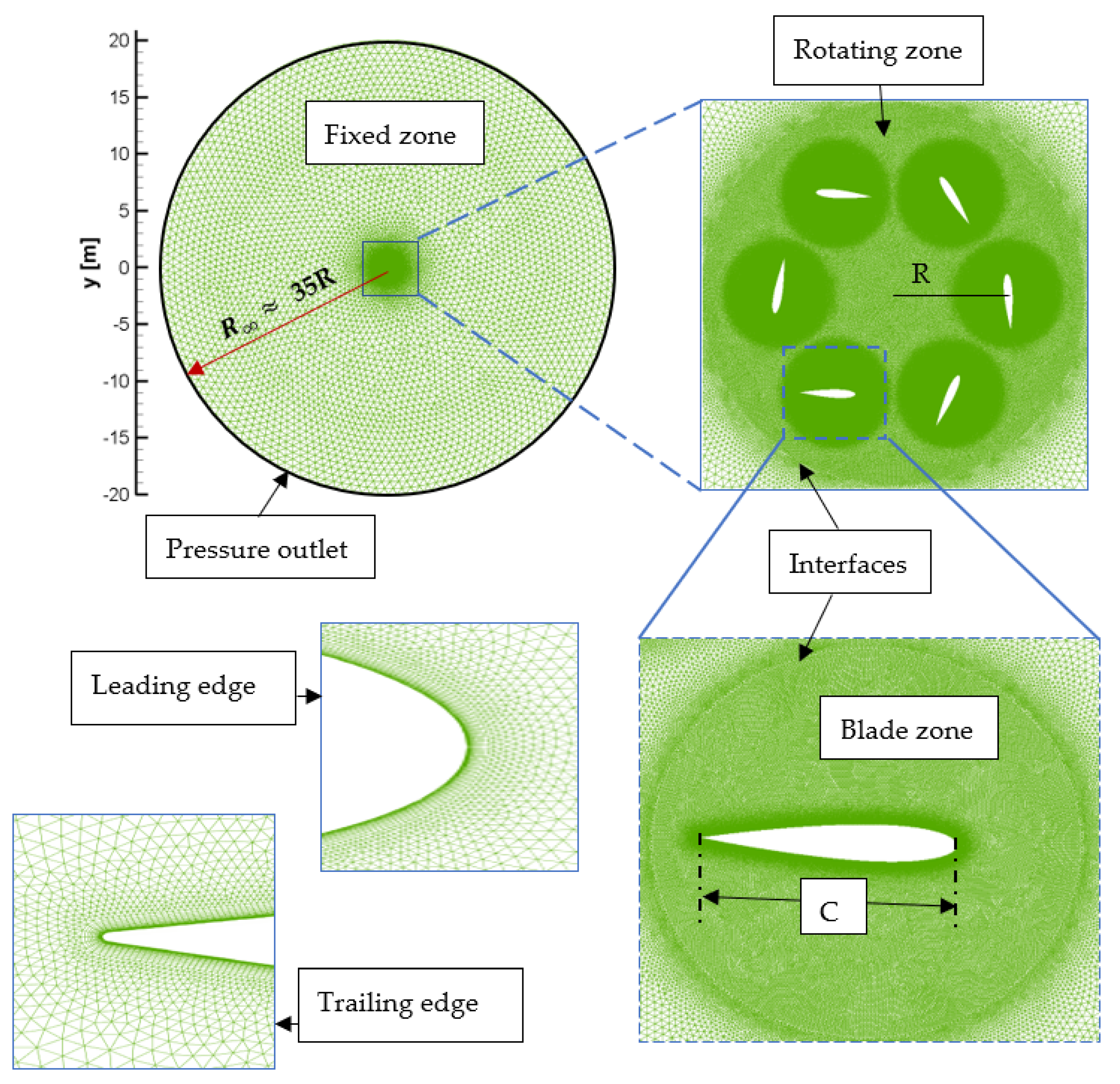
A two-dimensional computational domain was defined, adopting a circular shape with a radius of around 35 times the rotor radius. The unstructured mesh topology of the cyclorotor and boundary conditions are shown in Figure 2. The numerical domain of the cycloidal rotor comprises three distinct regions: the blade region, rotor region, and the environment region. Within this configuration, the blade domain interacts with the rotor domain through a sliding mesh interface, which also encompasses an area for the boundary layer to keep the y+ value close to 1., while the rotor itself maintains a constant angular velocity and interacts with the outer domain a via sliding mesh interface.

2.2. Fluid Flow Equations

In the current study, the 2D unsteady and incompressible approach based on Reynolds-averaged Navier–Stokes equations is used to depict the flow field. The governing equations encompass the filtered continuity and momentum conservation equations, and are expressed as follows:
u i x i = 0 .
ρ u i t + ( u i u j ) x j = p x i + x j μ u i x j + u j x i ρ u i u j ¯ + F p .
where ρ, μ, p and u represent the air density, the dynamic viscosity, the pressure and the mean velocity, respectively. i and j are the subscripts of velocity. ρ u i u j ¯ is the Reynolds stress, and lastly, F p is the external electrodynamic body force generated by the plasma actuator.

2.3. Plasma Model

The plasma body force, denoted as F p , is added into the momentum equation using user-defined functions (UDF) and integrated into the Fluent solver. For this study, the empirical approach outlined by Shyy et al. [66] is adopted to model the plasma body force effect per the assumptions made. Shyy’s model was chosen because it is one of the best-established plasma models in the literature, and although it is a simplified model, it offers results with very good accuracy when compared to that of alternative models. As demonstrated in a study conducted by Abdelraouf et al. [67], the effect of the plasma actuator on a NACA 0012 airfoil was evaluated using both Shyy [66] and Suzen [68] models. Their investigation revealed that the Shyy model offers reasonably accurate results for simulating plasma effects, particularly when assuming the linearity of the electric field, and provides nearly identical results to those of the Suzen model while requiring less time and fewer iterations to achieve a converged solution. Notably, this phenomenological model has been selected in numerous publications for unsteady applications, including those of De Giorgi et al. [69], Yu and Zheng [70], Lu Ma et al. [71], and Daree and Abbasi [72].
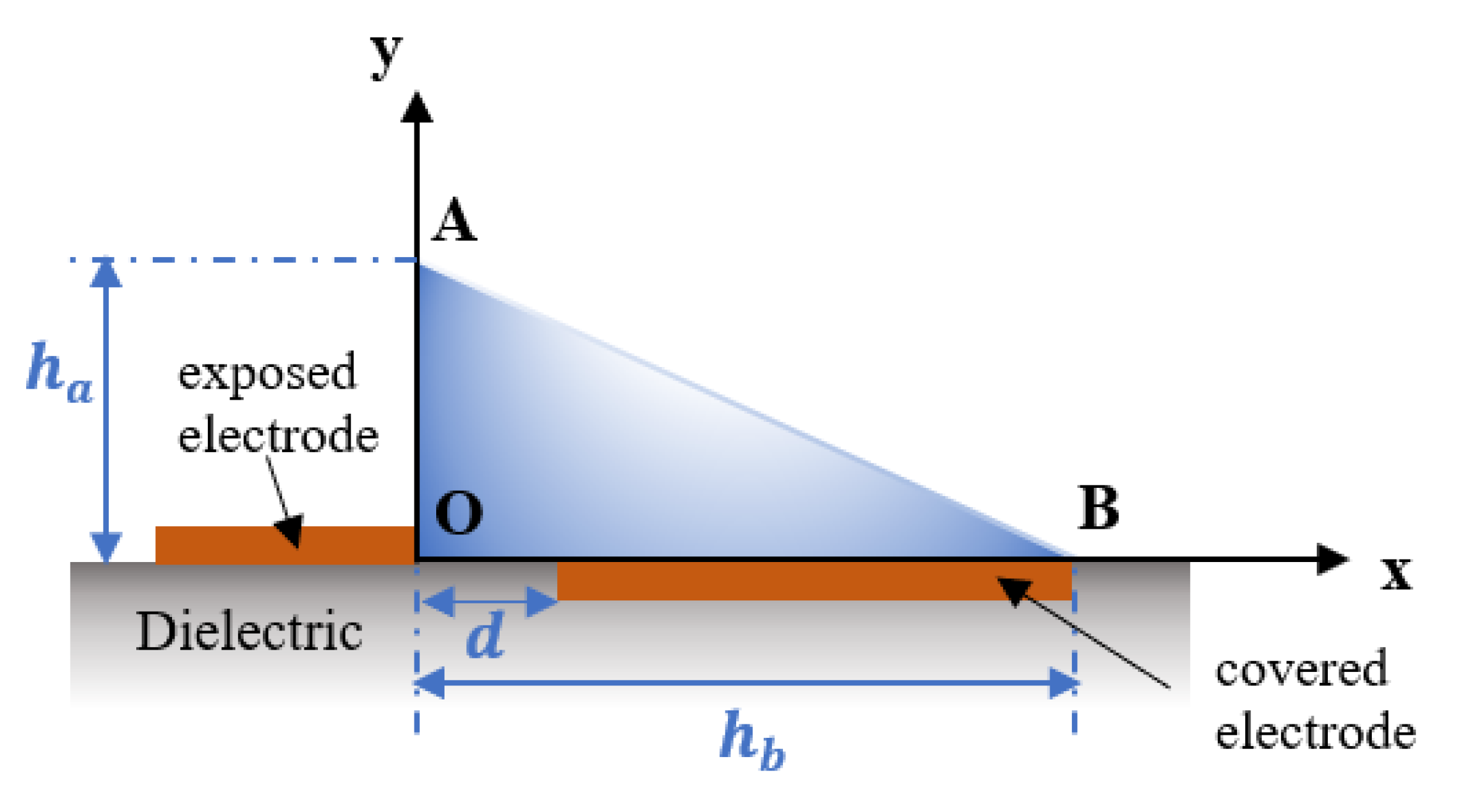
The plasma’s generated body force, per Shyy’s assumptions, is approximated based on calculations derived from the linearized electric field. In this model, the electric field lines exhibit a concentration towards the end of the exposed electrode, while they are uniformly distributed across the covered electrode. Shyy’s model simplifies the electric field by assuming that its intensity diminishes linearly as one moves further away from the internal edge of the exposed electrode, as illustrated in Figure 3.
The electric field variation is expressed as follows:
E = E 0 q 1 x q 2 y
where E 0 denotes the maximum electric field value between the two electrodes at a distance, d, and is defined by the following:
E 0 = U 0 d
q 1 and q 2 are defined using Equations (8) and (9) according to the electric field’s linear distribution, where E b r is the breakdown electric field strength; h a and h b correspond to the height and length of the triangular region, respectively.
q 1 = ( E 0 E b r ) h b
q 2 = ( E 0 E b r ) h a
The body force distribution generated by the plasma actuator is expressed via Equation (10), as follows:
F p = E υ ρ c e c α c δ Δ t
where υ is the applied voltage frequency, ρ c is the charge density, α c is the collision efficiency factor, e c is the constant electron charge, δ is the Dirac function, and Δ t is the plasma discharge time.
The correlations expressed by Yoon et al. [73] and Abdollahzadeh et al. [74] were used to calculate the power consumption of the actuator ( P p ) as follows:
P p = 2 π l p C p e q ( U 0 V b d ) 2
in which U 0 , V b d , and l p denote the applied voltage, the breakdown voltage, and the plasma length, respectively.
The equivalent capacitance of the DBD actuator, C p e q , can be calculated as follows:
C p e q = C p 1 C p 2 C p 1 + C p 2
where C p 1 and C p 2 are capacitor-equivalent properties of the electrodes and calculated via the following:
C p 1 = 2 π ϵ 0 ln ( 0.5 t e + λ d 0.5 t e )
C p 2 = π ϵ d ln ( 0.5 t e + 2 t d 0.5 t e )
where ϵ 0 = 8.85 × 10 19   F m , ϵ r = 3 and ϵ d = ϵ 0 ϵ r as provided in Abdollahzadeh et al. [74] and according to the Deby length, λ d , (mm), which is estimated via Equation (15):
λ d = 0.2 ( 0.3 × 10 3 U 0 7.42 × 10 4 )
Several parameters defining this dielectric barrier discharge (DBD) setup are described in detail by Shyy et al. [66] and the experimental data of Roth et al. [75], including the elementary charge, e c = 1.602 × 10⁻¹⁹ C; the charge density, ρ c = 1 × 10¹⁷ m−3; an applied voltage frequency of 3000 Hz; applied voltage of 4000 Vrms; breakdown electric field strength of 30 × 105 V/cm; and discharge time of 67 μs. The electrode thickness, t e = 0.1   mm , dielectric thickness t d = 0.75   mm and plasma length l p = 3   mm ; using these parameters, the power consumption of the plasma actuator is given by P p = 1.112   W , as described in Benmoussa and Páscoa [37].

2.4. Solver Setting

The 2D numerical simulations were performed using the commercial CFD software ANSYS FLUENT. The movements of the rotor and the blades, as well as the body force terms of the DBD model, were implemented through a user-defined functions (UDF) framework provided within this software.
The second-order linear-upwind scheme was selected for space interpolation, and the Gauss–Seidel iteration method was employed for solving discrete equations with a pressure–velocity coupled algorithm. For turbulence modeling, the k-ω SST model was selected. This model offers the advantage of a two-equation eddy viscosity turbulence approach, where the free stream is effectively resolved using k-ε, and the k-ω model is used to address the shear layer regions. This model was identified as a suitable choice in several studies [76,77,78,79,80] demonstrating its ability to predict the main flow features around the blades.
The airflow was treated as incompressible, with a density of 1.225 kg/m3 and a viscosity of 1.7894 × 10⁻⁵ kg/ms. Convergence was considered achieved when the residuals of all variables remained below 10⁻⁵, and the time step size was chosen to achieve a rotor rotation of 0.1° per time step, allowing us to capture the unsteady behavior of the flow.

3. Results and Interpretations

3.1. Mesh Independence Test

In order to ascertain the optimal mesh density for accurate and reliable results, it is crucial to assess result dependency on mesh configuration. Three distinct meshes were utilized, consisting of 590,102, 734,276 and 810,216 cells. The time history of the lift coefficient results is depicted in Figure 4. It is observed that after 10 full rotations, the cyclorotor achieves stability with periodic oscillations, and meshes 2 and 3 exhibit a negligible impact on the results. Therefore, mesh 2, with 734,276 cells across the entire computational domain (Figure 2), was selected for this analysis.

3.2. Model Validation

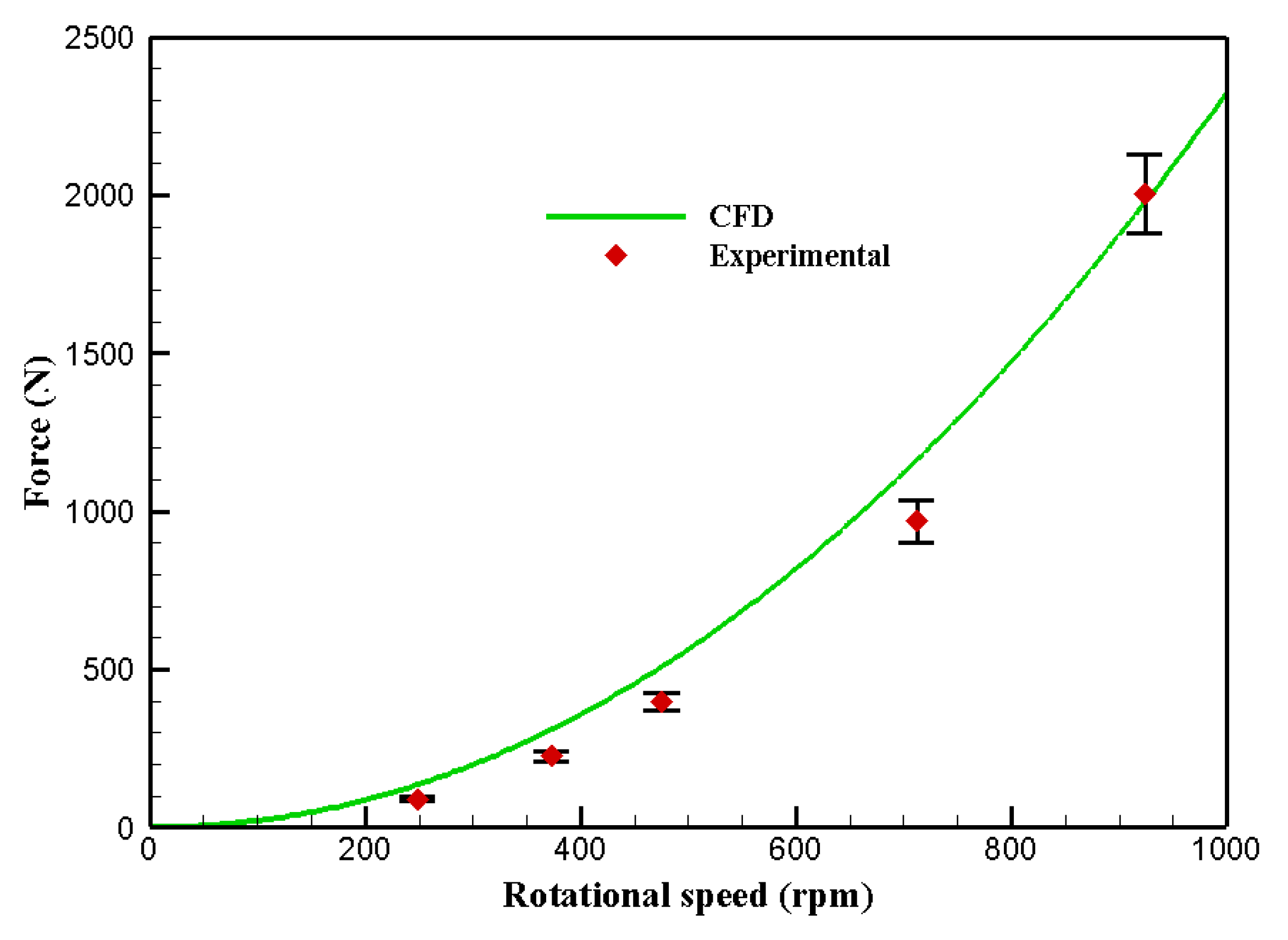
The validation procedure has been conducted for both the computational model and the DBD plasma model. Experimental data for the IAT21 L3 cycloidal rotor configuration [81], whose characteristics are illustrated in Table 1, were used to validate the numerical model.
The simulation results are computed over twenty cycles, with the converged periodic solution achieved after ten full rotations; the average data obtained from the last ten cycles are used to determine the thrust. These results are measured for each blade and then integrated to calculate the total thrust. As illustrated in Figure 5, the computed results exhibit a good trend as compared to that of the experimental data [81].
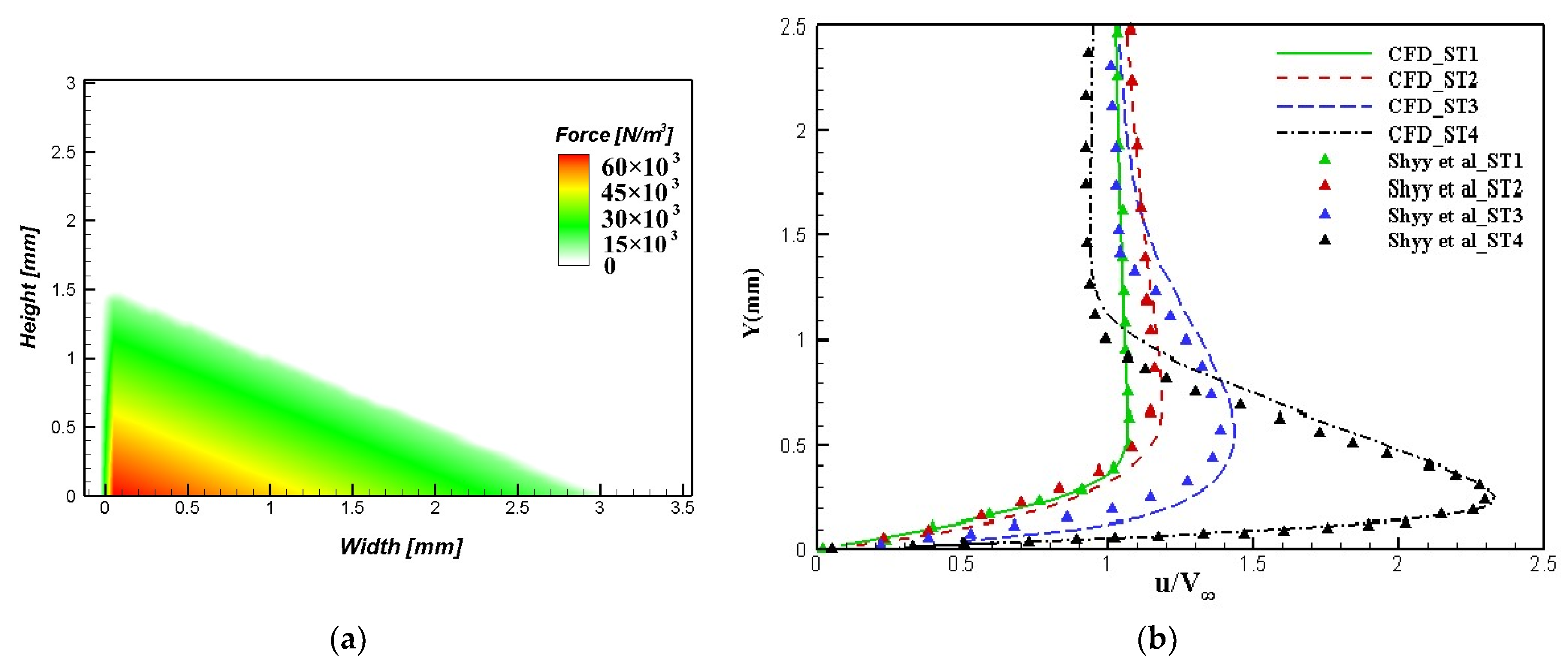
Afterwards, the DBD plasma model was validated using a numerical simulation conducted by Shyy et al. [66] on a flat plate with dimensions of 0.0205 m. The computational domain is a 2D rectangular space situated on an x–y plane. Within this domain, a plasma actuator was positioned at the bottom, embedded in the solid wall. Figure 6a presents the CFD-modeled body force distribution characterized by a height ( h a ) of 1.5 mm and width ( h b ) of 3 mm. In Figure 6b, velocity profiles are shown, normalized by the freestream velocity ( V ) of 5 m/s, at four different horizontal positions. ST1 and ST2 are situated upstream of the actuator, while ST3 and ST4 are positioned downstream. The figure also provides a comparative analysis of our results with those of Shyy et al. [59]. Remarkably, very close agreement is observed across all four sections.

3.3. Cyclorotor Base Case

In this study, the pitching axis is situated at 35% of the chord, and the rotor rotates at a speed of 100 rpm in a counterclockwise direction while operating in hover mode. The pitching schedule generates an asymmetric pitching profile, ranging from θ m a x   + 36° in the top section of the rotor at Ψ = 90° to θ m i n = −39° in the bottom section of the rotor at Ψ = 270°.
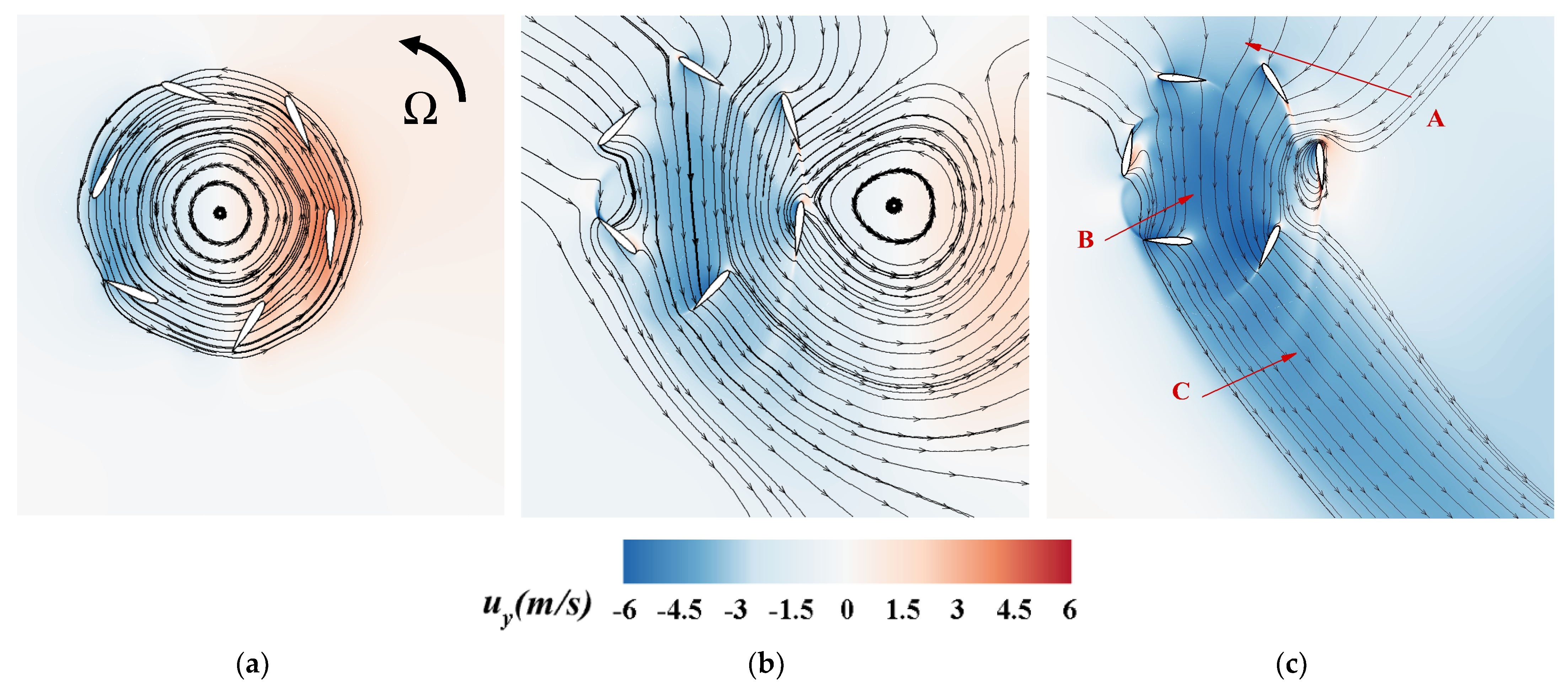
The flow patterns generated by cycloidal rotors undergo numerous curvatures and deformations as they produce the downwash jet. Figure 7 illustrates the downwash velocity contour presented by the induced velocity in the negative y-direction and the flow pattern of a cycloidal rotor operating in hover mode at 100 rpm and at different times ( t ) . Analyzing Figure 7a, we observe that as the blades start rotating, a distinct recirculation zone is formed in which the streamlines exhibit a symmetrical and closed pattern, synchronized with the cyclorotor’s counterclockwise rotation. As the blades rotate further in Figure 7b, this zone gradually shifts towards the right. Subsequently, the flow enters and exits the rotor cage, generating a slight right-inclined downwash. This evolution arises due to the rotation of the blades, variations in velocity between top and bottom positions that are a result of cyclorotor movement, and interactions with the wakes generated by the blades. As the cyclorotor continues to rotate, we observe the incoming flow descending directly into the rotor cage. Upon closer examination, we observe the presence of circulation in the flow around the blade located at 0°, as shown in Figure 7c. This flow undergoes three sequential stages. Firstly, in zone A, it enters the inhaling region, drawing from the majority of the upper half of the cyclorotor. Secondly, it experiences a downward flow within the rotor cage, descending into the interior in zone B. Lastly, as it exits the lower portion of the cyclorotor, it generates a downwash jet that inclines slightly to the right (zone C).
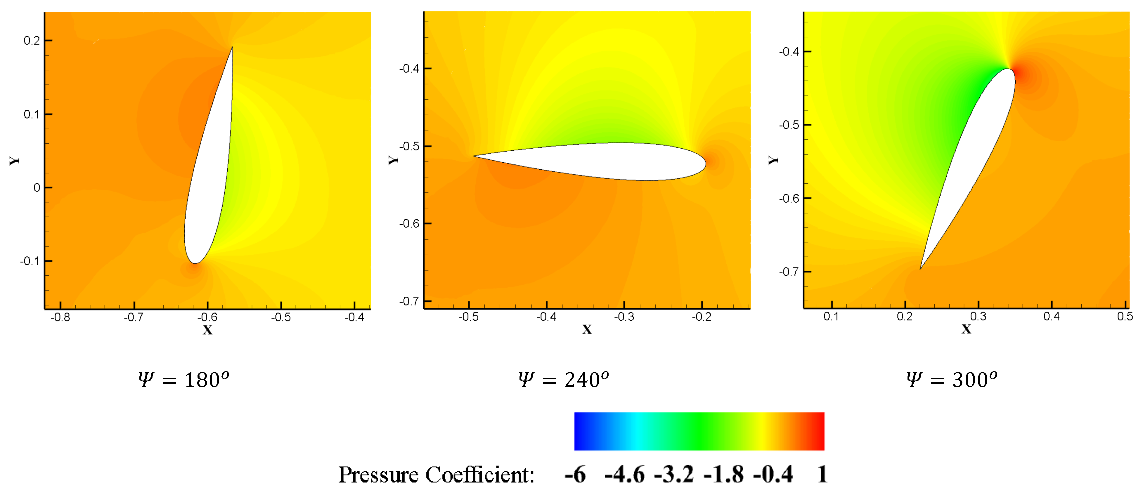
Figure 8 shows the pressure coefficient contour of the cyclorotor blades in different azimuth positions. Notably, each blade transitions from the pressure side to the suction side during one full rotation. This transition occurs as the flow accelerates on the pressure side, resulting in lower pressure. Subsequently, this side transforms into the pressure side, where the flow velocity decreases, leading to higher pressure. When the pressure beneath the airfoil’s lower surface surpasses that on the upper surface, it induces an upward force on the blade, generating lift. It is also evident that at 240° and 300° in the lower half, the blade exhibits higher pressure on its outer surface compared to its inner surface, indicating that it generates considerably more lift than when it is operating in the upper half at 60° and 120°, respectively. Additionally, at 120° the blade experiences greater pressure on its rear upper surface, explaining the negative lift produced in this position.
Figure 9 illustrates the lift coefficient (red line) and the pitching angle variations (blue dashed line) as a function of azimuth positions of a cyclorotor blade for a full revolution. It is evident that the blade of the cyclorotor describes a cycloidal path, with an external up-stroke motion from 0° to 90°, during which the pitching angle increases from −3° until it reaches the maximum of 36° in the topmost position. A decrease in lift force is observed before the lift starts increasing, due to the transition from a negative to a positive angle of attack. Moving from 90° to 180°, the blade undergoes an external downstroke, resulting in a decrease in the angle of attack and the production of negative lift. In the lower half of the rotation, an internal up-stroke spans from 180° to 270°, during which the pitch angle increases, reaching a maximum of 39°, and produces a positive lift, before the blade returns to its initial angle of attack, implying an internal downstroke from 270° to 360°. Altering the angle of attack during rotation plays a crucial role in generating lift force. Nevertheless, these variations are not favorable throughout the entire rotation cycle.
Furthermore, the analysis reveals that the lower section of the cyclorotor generates greater vertical forces compared to those generated by the upper section. This phenomenon is a result of the blades’ virtual camber effect [14]. The upper half primarily serves as the primary inlet region, where the airflow is drawn inward from near-zero velocities. Compared to the upper half, the lower part encounters a concentrated flow with significantly higher velocities.

3.4. Effect of DBD Plasma Actuator

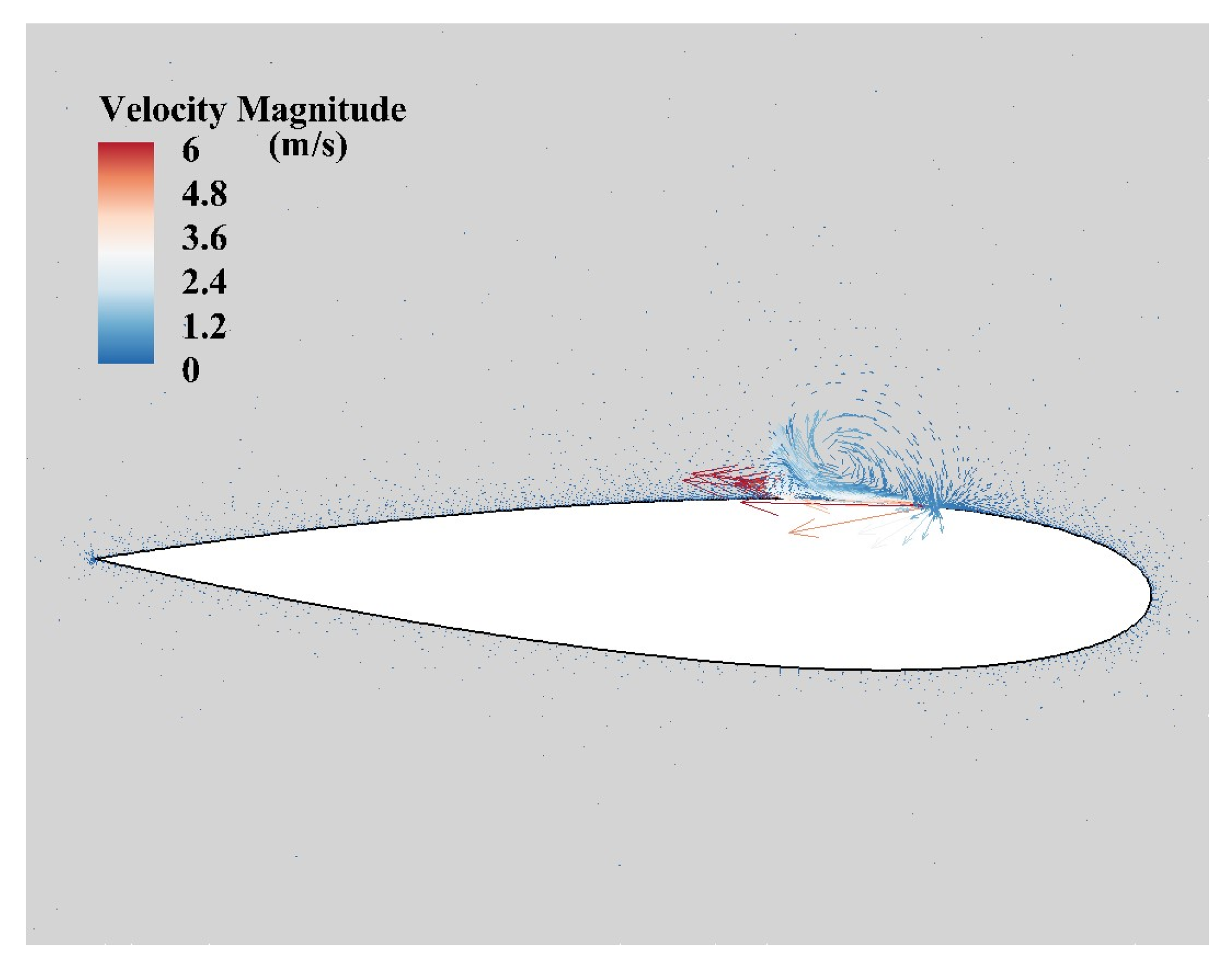
To analyze the effect of the plasma actuator on the cyclorotor’s performance, a DBD plasma actuator is applied to each cycloidal blade on both the inner and outer sides, positioned at a 0.2 chord length from the leading edge. Figure 10 shows the induced velocity of the inner DBD actuator (inside the rotor cage) in quiescent air on a cyclorotor blade at a 240° azimuth position. The ionized air in the presence of the electric filed gradient generated by the electrodes results in a body force vector which drives the fluid along the surface of the blade, from the exposed to the covered electrode. From this figure, we observe that the plasma actuator interacts with the adjacent flow and creates a wall jet with a significant magnitude that can be used to manipulate the flow around the airfoil and increase the lift.
Figure 11 shows the effect of the plasma actuation side on the vorticity magnitude field for a cyclorotor blade during a rotating cycle. In this figure, four different azimuth positions are shown, referring to the places where the blade introduces an upstroke and a downstroke motions.
Notable distinctions are observed among the four investigated scenarios. In Figure 11a, vorticity forms on both the upper and lower surfaces of the airfoil, albeit with relatively low intensity on the leading edges; it significantly influences lift generation and, consequently, the cyclorotor’s performance. In the upper half, vortices on this blade’s upper section are more pronounced, while as the blade proceeds to the lower half, vortices shift to the blade’s bottom surface. Figure 11b presents the case where the plasma actuator positioned on the inner side of the airfoil (inner actuation) is activated. Here, plasma actuation exhibits a stronger effect in the lower half of the cyclorotor’s trace as compared to that in the upper half. Here, vorticity on the inner surface tends to flatten and diminish at positions 240°and 300°. In Figure 11c, the plasma actuator on the outer side of the airfoil (outside the cage) is activated. In this instance, external actuation proves more efficient in the upper half, causing a reduction in the vorticity’s strength appearing on the upper surface of the blade, which is the converse of the case in the lower trajectory, where no beneficial effect is observed.
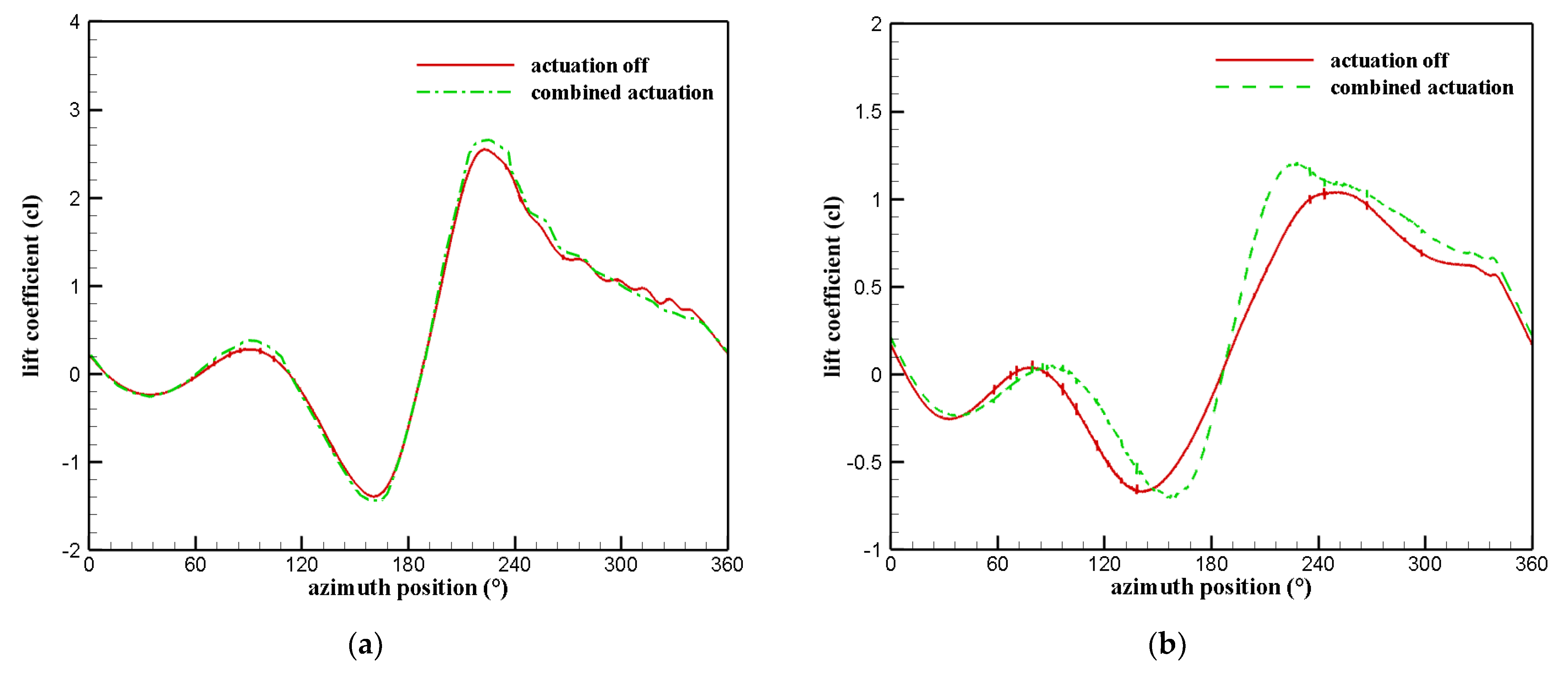
In Figure 12, we present the lift coefficient comparisons for the cases with and without plasma actuation. Analyzing Figure 12a, it is evident that plasma actuation affects the aerodynamic force coefficient generated by the cyclorotor blade. Notably, the inner actuator demonstrates a beneficial effect on the lift coefficient between 200° and 340°, while the outer actuator leads to an increase in the lift coefficient between 90° and 140°. Consequently, each actuator can enhance cyclorotor performance only during specific azimuth positions. To achieve this, combined control actuation is applied based on the lift results. Figure 12b illustrates the impact of control actuation on the lift force, revealing that the combination effectively enhances the lift coefficient in the upper half when the outer actuator is activated and in the lower half when the inner actuator is activated. However, a decrease in the lift coefficient is observed between 150° and 180°, which is attributed to the delay time when turning off the upper actuator while turning on the lower one.
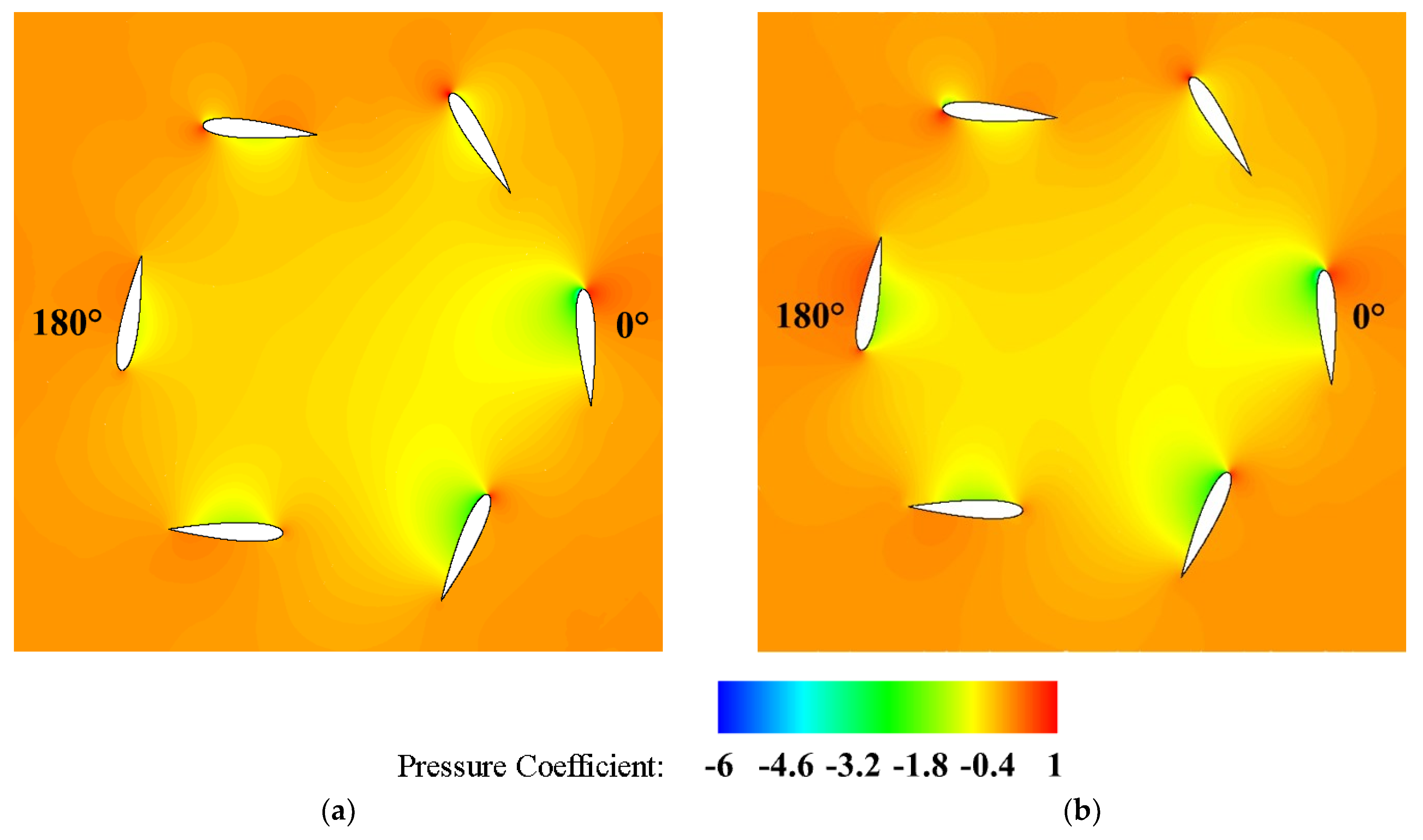
Furthermore, Figure 13 presents a detailed view of the pressure coefficient contour distribution on the cyclorotor blades. This visualization allows us to gain a deeper understanding of the aerodynamic impact of both the clean (no actuation) and combined actuation case. Significant differences are evident in the upper half when the outer actuator is activated, and in the lower half when the inner actuator is activated. The pressure contours on the suction side are lower for control actuation compared to the case without actuation, leading to flow acceleration and a higher pressure difference between the suction and pressure sides. Therefore, more lift force is generated, which enhances the overall efficiency of the cyclorotor.
Figure 14 demonstrates that combined control actuation results in a notably more intense and concentrated downwash velocity. Additionally, the thrust angle decreases by 3° as compared to that with the clean cyclorotor, indicating changes in the flow dynamics induced by the plasma actuators. This leads to a significant reduction in the incidence angle and the associated virtual camber effects, resulting in improved stability for the cyclorotor during hover and vertical movements.
In addition, in order to compare the operation of the plasma-enhanced cycloidal rotor at different rotational speeds, the results obtained for 100 rpm were compared with the results obtained for 200 rpm. Figure 15 illustrates the impact of plasma actuation on the lift coefficient of a cyclorotor blade operating at these two rotational speeds for the same control application. It is evident that the lift force increases as the rotational speed is raised to 200 rpm compared to that when the latter is raised to 100 rpm. Additionally, we can observe that the plasma actuator is more effective and significantly improves the lift coefficient at lower rotational speeds. This effectiveness is attributed to the blade operating at a relatively higher angle of attack at 100 rpm, where the DBD plasma has a strong influence in reducing the effective angle and mitigating the blade’s virtual camber effect.
Overall, the presented results demonstrate the great potential of DBD plasma actuators to optimize the vectorized jet produced by cycloidal rotors. The proposed combined actuation clearly increases the lift forces for different rotational speeds; however, at lower rotation speeds the plasma optimization is much more significant. On the other hand, considering the application of plasma-enhanced cycloidal thrusters in airships, the lift forces of the aerial vehicle are mostly produced via aerostatic means and thus, this is an ideal application for plasma-enhanced cycloidal rotors, since they can operate at lower rotational speeds, being more effective, and still providing the required maneuverability to the airship.

4. Conclusions

Airships have great potential for several applications and require much lower fuel consumption than commercial airplanes do; however, they still present maneuverability issues. In the current work, we proposed and numerically studied a novel concept of plasma-enhanced cycloidal rotor thrusters for the increased controllability and maneuverability of airships. Cycloidal rotors are rotating wing devices that, by manipulating the operational parameters, offer the unique ability to dynamically alter both the magnitude and direction of the thrust vector, which makes them a solution to the maneuverability issues of airships. In addition, the implementation of DBD plasma actuators on the cycloidal rotor blades allows the active control of the separation of the flow and the effective optimization of the lift and vectorization capabilities of this innovative device.
Numerical results were obtained in order to understand the operation of the cycloidal rotor with and without plasma actuators. By simulating the cycloidal rotor base case, we concluded that, depending on the blade position, it will create a different impact on the lift produced. We also demonstrated that angle of attack variations play a crucial role in the generated lift; however, these variations are not favorable throughout the entire rotation cycle. The effect of the plasma actuator on the cycloidal rotor blades was investigated, and it was shown that plasma actuation allows the manipulation of vorticity and lift forces. In addition, smart combined actuation that takes advantage of the actuation of inner and outer actuators only in the key azimuth positions was proposed. This combined method of operation allows a maximization of the plasma flow control effect on the cycloidal rotor blades. In addition, we concluded that combined control actuation resulted in a notably more intense and concentrated downwash velocity produced by the cycloidal rotor device. This smart control effect allowed the obtention of a 27% improvement in lift forces.
Combined plasma actuation was also compared for different cycloidal rotor rotational speeds. We concluded that although plasma actuation is clearly more effective at lower rotational speeds, it is also effective in increasing the lift forces at 200 rpm. The increased effectiveness at lower rotational speeds is attributed to the blade operating at a relatively higher angle of attack, where the DBD plasma has a strong influence on reducing the effective angle and mitigating the blade’s virtual camber effect. Since airships produce the lift mainly via aerostatic means, we concluded that plasma-enhanced cycloidal thrusters are an optimum solution with which to overcome the maneuverability issues of these aerial vehicles.

Author Contributions

Conceptualization, A.B. and F.F.R.; methodology, A.B.; software, A.B.; validation, A.B.; formal analysis, A.B., F.F.R. and J.C.P.; investigation, A.B., F.F.R. and J.C.P.; resources, J.C.P.; writing—original draft preparation, A.B. and F.F.R.; writing—review and editing, A.B., F.F.R. and J.C.P.; supervision, J.C.P.; project administration, F.F.R. and J.C.P.; funding acquisition, F.F.R. and J.C.P. All authors have read and agreed to the published version of the manuscript.

Funding

This research was funded by R&D Project ‘‘GreenAuto: Green innovation for the Automotive Industry’’, founded by the incentive system ‘‘Agendas Mobilizadoras para a Inovação Empresarial’’ (Portugal) and by C-MAST (Center for Mechanical and Aerospace Science and Technology), Research Unit No. 151, project grant number UIDB/00151/2020.

Data Availability Statement

Data are contained within the article.

Conflicts of Interest

The authors declare no conflict of interest.

References

  1. Manikandan, M.; Pant, R.S. Research and Advancements in Hybrid Airships—A Review. Prog. Aerosp. Sci. 2021, 127, 100741. [Google Scholar] [CrossRef]
  2. Chen, L.; Zhou, G.; Yan, X.J.; Duan, D.P. Composite Control of Stratospheric Airships with Moving Masses. J. Aerosp. Eng. 2012, 49, 794–801. [Google Scholar] [CrossRef]
  3. Manikandan, M.; Vaidya, E.; Pant, R.S. Design and analysis of hybrid electric multi-lobed airship for cargo transportation. Sustain. Energy Technol. Assess. 2022, 51, 101892. [Google Scholar] [CrossRef]
  4. Bonnici, M.; Tacchini, A.; Vucinic, D. Long Permanence High Altitude Airships: The Opportunity of Hydrogen. Eur. Transp. Res. Rev. 2014, 6, 253–266. [Google Scholar] [CrossRef]
  5. Cimarelli, A.; Madonia, M.; Angeli, D.; Dumas, A. Aerodynamic Study of Advanced Airship Shapes. J. Aerosp. Eng. 2017, 30, 04016087. [Google Scholar] [CrossRef]
  6. Smith, T.; Bingham, C.; Stewart, P.; Allarton, R.; Stewart, J. Energy harvesting and power network architectures for the multibody advanced airship for transport high altitude cruiser–feeder airship concept. Proc. Inst. Mech. Eng. Part G J. Aerosp. Eng. 2013, 227, 586–598. [Google Scholar] [CrossRef]
  7. Boschma, J.H. Modern Aviation Applications for Cycloidal Propulsion. In Proceedings of the 1st AIAA Aircraft, Technology Integration, and Operations Forum, Los Angeles, CA, USA, 16–18 October 2001. [Google Scholar] [CrossRef]
  8. Onda, M.; Matsuuchi, K.; Ohtsuka, N.; Kimura, Y. Cycloidal Propeller and Its Application to Advanced LTA Vehicles. In Proceedings of the AIAA’s 3rd Annual Aviation Technology, Integration, and Operations (ATIO) Forum, Denver, CO, USA, 17–19 November 2003. [Google Scholar] [CrossRef]
  9. Onda, M.; Matsuuchi, K.; Kimura, Y.; Hashimoto, S. Aerobatic Airship Robot with Advanced Propulsors. In Proceedings of the IEEE Conference on Robotics and Automation, Minato, Japan, 18–19 November 2004; Available online: https://ieeexplore.ieee.org/stamp/stamp.jsp?arnumber=1425014 (accessed on 23 August 2023).
  10. Onda, M.; Sano, M.; Iwata, K.; Tomita, K.; Watanabe, M.; Koyama, N.; Akinaga, W.; Maruyama, M. Airship-Type Crane Robot with Cycloidal Propellers. In Proceedings of the 6th AIAA Aviation Technology, Integration, and Operations Conference, Wichita, KS, USA, 25–27 September 2006. [Google Scholar] [CrossRef]
  11. Benmoussa, A.; Gamboa, P.V. Effect of Control Parameters on Hybrid Electric Propulsion UAV Performance for Various Flight Conditions: Parametric Study. Appl. Mech. 2023, 4, 493–513. [Google Scholar] [CrossRef]
  12. Hwang, I.S.; Min, S.Y.; Lee, C.H.; Kim, S.J. Development of a Four-Rotor Cyclocopter. J. Aircr. 2008, 45, 1251–1257. [Google Scholar] [CrossRef]
  13. Xisto, C.M.; Leger, J.A.; Páscoa, J.C.; Gagnon, L.; Masarati, P.; Angeli, D.; Dumas, A. Parametric Analysis of a Large-Scale Cycloidal Rotor in Hovering Conditions. J. Aerosp. Eng. 2016, 30, 04016066. [Google Scholar] [CrossRef]
  14. Benedict, M.; Jarugumilli, T.; Chopra, I. Effect of Rotor Geometry and Blade Kinematics on Cycloidal Rotor Hover Performance. J. Aircr. 2013, 50, 1340–1352. [Google Scholar] [CrossRef]
  15. Jarugumilli, T.; Benedict, M.; Chopra, I. Wind tunnel studies on a micro air vehicle-scale cycloidal rotor. J. Am. Helicopter Soc. 2014, 59, 1–10. [Google Scholar] [CrossRef]
  16. Sachse, H. Kirsten-Boeing Propeller; National Advisory Committee for Aeronautics: Washington, DC, USA, 1926.
  17. Garrick, I.E. Propulsion of a Flapping and Oscillating Airfoil; National Advisory Committee for Aeronautics: Washington, DC, USA, 1937.
  18. Wheatley, J.B.; Windler, R. Wind-Tunnel Tests of a Cyclogiro Rotor; National Advisory Committee for Aeronautics: Washington, DC, USA, 1935.
  19. Wheatley, J.B. Simplified Aerodynamic Analysis of the Cyclogiro Rotating Wing System; National Advisory Committee for Aeronautics: Washington, DC, USA, 1930.
  20. Boirum, C.G.; Post, S.L. Review of historic and modern cyclogyro design. In Proceedings of the 45th AIAA/ASME/SAE/ASEE Joint Propulsion Conference and Exhibit, Denver, CO, USA, 2–5 August 2009. [Google Scholar] [CrossRef]
  21. Xisto, C.M.; Páscoa, J.C.; Abdollahzadeh, M.; Leger, J.A.; Masarati, P.; Gagnon, L.; Schwaiger, M.; Wills, D. PECyT—Plasma Enhanced Cycloidal Thruster. In Proceedings of the 50th AIAA/ASME/SAE/ASEE Joint Propulsion Conference, Cleveland, OH, USA, 28–30 July 2014. [Google Scholar] [CrossRef]
  22. Gibbens, R.P.; Boschma, J.H. Construction and Testing of a New Aircraft Cycloidal Propeller. In Proceedings of the 13th Lighter-Than-Air Systems Technology Conference, Norfolk, VA, USA, 28 June–1 July 1999; pp. 131–140. [Google Scholar] [CrossRef]
  23. Hwang, I.S.; Min, S.Y.; Kim, M.K.; Kim, S.J. Multidisciplinary Optimal Design of Cyclocopter Blade System. In Proceedings of the 46th AIAA/ASME/ASCE/AHS/ASC Structures, Structural Dynamics and Materials Conference, Austin, TX, USA, 18–21 April 2005; pp. 6005–6011. [Google Scholar] [CrossRef]
  24. Hwang, I.S.; Hwang, C.S.; Kim, S.J. Structural Design of Cyclocopter Blade System. In Proceedings of the 46th AIAA/ASME/ASCE/AHS/ASC Structures, Structural Dynamics and Materials Conference, Austin, TX, USA, 18–21 April 2005; pp. 2743–2749. [Google Scholar] [CrossRef]
  25. Benedict, M.; Ramasamy, M.; Chopra, I.; Leishman, J.G. Performance of a Cycloidal Rotor Concept for Micro Air Vehicle Applications. J. Am. Helicopter Soc. 2010, 55, 22002. [Google Scholar] [CrossRef]
  26. Benedict, M.; Mattaboni, M.; Chopra, I.; Masarati, P. Aeroelastic Analysis of a Micro-Air-Vehicle-Scale Cycloidal Rotor in Hover. AIAA J. 2012, 49, 2430–2443. [Google Scholar] [CrossRef]
  27. Leger, J.A.; Páscoa, J.C.; Xisto, C.M. Analytical Modeling of a Cyclorotor in Hovering State. Proc. Inst. Mech. Eng. Part G J. Aerosp. Eng. 2015, 229, 2163–2177. [Google Scholar] [CrossRef]
  28. Monteiro, J.A.L.; Páscoa, J.C.; Xisto, C.M. Aerodynamic Optimization of Cyclorotors. Aircr. Eng. Aerosp. Tech. 2016, 88, 232–245. [Google Scholar] [CrossRef]
  29. Gagnon, L.; Morandini, M.; Quaranta, G.; Muscarello, V.; Masarati, P. Aerodynamic models for cycloidal rotor analysis. Aircr. Eng. Aerosp. Technol. 2016, 88, 215–231. [Google Scholar] [CrossRef]
  30. Singh, K.; Páscoa, J.C. Numerical Modeling of Stall and Poststall Events of a Single Pitching Blade of a Cycloidal Rotor. J. Fluids Eng. 2019, 141, 011103. [Google Scholar] [CrossRef]
  31. Schwaiger, M.; Wills, D. D-Dalus VTOL—Efficiency Increase in Forward Flight. Aircr. Eng. Aerosp. Tech. 2016, 88, 594–604. [Google Scholar] [CrossRef]
  32. Cycloidal Rotor Optimized for Propulsion | CROP | Project | Fact Sheet | FP7 | CORDIS | European Commission, (n.d.). Available online: https://cordis.europa.eu/project/id/323047 (accessed on 7 August 2023).
  33. Habibnia, R.M.; Pascoa, J.C. Performance Optimization of Forward-Flight and Lift-Up Phases in a Cycloidal Rotor Using an Active Control Mechanism. J. Aerosp. Eng. 2021, 34, 04021039. [Google Scholar] [CrossRef]
  34. Habibnia, R.M.; Pascoa, J. Active Control Assessments Towards Optimizing the Performance of a Cycloidal Rotor at Hover. Aerosp. Sci. Technol. 2021, 119, 107141. [Google Scholar] [CrossRef]
  35. Habibnia, M.; Pascoa, J. ANN Assisted Flow Modeling and Analysis for a Cyclorotor in Ground Effect. Aerosp. Sci. Technol. 2019, 95, 105495. [Google Scholar] [CrossRef]
  36. Benmoussa, A.; Páscoa, J.C. Performance Improvement and Start-Up Characteristics of a Cyclorotor Using Multiple Plasma Actuators. Meccanica 2021, 56, 2707–2730. [Google Scholar] [CrossRef]
  37. Benmoussa, A.; Páscoa, J.C. Cycloidal Rotor Coupled with DBD Plasma Actuators for Performance Improvement. Aerosp. Sci. Technol. 2021, 110, 106468. [Google Scholar] [CrossRef]
  38. Liu, C.; Roth, J.R. An Atmospheric Glow Discharge Plasma For Aerodynamic Boundary Layer Control. In Proceedings of the 1994 IEEE 21st International Conference on Plasma Sciences (ICOPS), Santa Fe, NM, USA, 6–8 June 1994. [Google Scholar]
  39. Roth, J.R.; Sherman, D.M.; Wilkinson, S.P. Boundary Layer Flow Control with a One Atmosphere Uniform Glow Discharge Surface Plasma. In Proceedings of the 36th AIAA Aerospace Sciences Meeting and Exhibit, Reno, NV, USA, 12–15 January 1998. [Google Scholar] [CrossRef]
  40. Rodrigues, F.; Abdollahzadehsangroudi, M.; Nunes-Pereira, J.; Páscoa, J. Recent Developments on Dielectric Barrier Discharge (DBD) Plasma Actuators for Icing Mitigation. Actuators 2022, 12, 5. [Google Scholar] [CrossRef]
  41. Benard, N.; Moreau, E. Electrical and mechanical characteristics of surface AC dielectric barrier discharge plasma actuators applied to airflow control. Exp. Fluids 2014, 55, 1–43. [Google Scholar] [CrossRef]
  42. Hink, R.; Pipa, A.V.; Schafer, J.; Caspari, R.; Weichwald, R.; Foest, R.; Brandenburg, R. Influence of dielectric thickness and electrode structure on the ion wind generation by micro fabricated plasma actuators. J. Phys. D Appl. Phys. 2020, 53, 405201. [Google Scholar] [CrossRef]
  43. Pescini, E.; Suma, A.; De Giorgi, M.G.; Francioso, L.; Ficarella, A. Optimization of Plasma Actuator Excitation Waveform and Materials for Separation Control in Turbomachinery. Energy Procedia 2017, 126, 786–793. [Google Scholar] [CrossRef]
  44. Wang, J.J.; Choi, K.S.; Feng, L.H.; Jukes, T.N.; Whalley, R.D. Recent developments in DBD plasma flow control. Prog. Aerosp. Sci. 2013, 62, 52–78. [Google Scholar] [CrossRef]
  45. Singh, K.P.; Roy, S. Force approximation for a plasma actuator operating in atmospheric air. J Appl Phys. 2008, 103, 13305. [Google Scholar] [CrossRef]
  46. Moreau, E.; Sosa, R.; Artana, G. Electric wind produced by surface plasma actuators: A new dielectric barrier discharge based on a three-electrode geometry. J. Phys. D Appl. Phys. 2008, 41, 115204. [Google Scholar] [CrossRef]
  47. Erfani, R.; Erfani, T.; Utyuzhnikov, S.V.; Kontis, K. Optimisation of multiple encapsulated electrode plasma actuator. Aerosp. Sci. Technol. 2013, 26, 120–127. [Google Scholar] [CrossRef]
  48. Nunes-Pereira, J.; Rodrigues, F.F.; Abdollahzadehsangroudi, M.; Páscoa, J.C.; Lanceros-Mendez, S. Improved Performance of Polyimide Cirlex-Based Dielectric Barrier Discharge Plasma Actuators for Flow Control. Polym. Adv. Technol. 2022, 33, 1278–1290. [Google Scholar] [CrossRef]
  49. Portugal, S.; Roy, S.; Lin, J. Functional relationship between material property, applied frequency and ozone generation for surface dielectric barrier discharges in atmospheric air. Sci. Rep. 2017, 7, 6388. [Google Scholar] [CrossRef] [PubMed]
  50. Shvydyuk, K.O.; Rodrigues, F.F.; Nunes-Pereira, J.; Páscoa, J.C.; Lanceros-Mendez, S. Long-Lasting Ceramic Composites for Surface Dielectric Barrier Discharge Plasma Actuators. J. Eur. Ceram. Soc. 2023, 43, 6112–6121. [Google Scholar] [CrossRef]
  51. Huang, J.; Corke, T.C.; Thomas, F.O. Plasma actuators for separation control of low-pressure turbine blades. AIAA J. 2016, 44, 51–57. [Google Scholar] [CrossRef]
  52. Das Gupta, A.; Roy, S. Effect of plasma actuator control parameters on a transitional flow. J. Phys. D Appl. Phys. 2018, 51, 135204. [Google Scholar] [CrossRef]
  53. Mclaughlin, T.E.; Munska, M.D.; Vaeth, J.P.; Dauwalter, T.E.; Goode, J.R.; Siegeli, S.G. Plasma-Based Actuators for Cylinder Wake Vortex Control. In Proceedings of the 2nd AIAA Flow Control Conference, Portland, OR, USA, 28 June–1 July 2004. [Google Scholar] [CrossRef]
  54. Anzalotta, C.; Joshi, K.; Fernandez, E.; Bhattacharya, S. Effect of forcing the tip-gap of a NACA0065 airfoil us-ing plasma actuators: A proof-of-concept study. Aerosp. Sci. Technol. 2020, 107, 106268. [Google Scholar] [CrossRef]
  55. Bhattacharya, S.; Gregory, J.W. The optimum wavelength of spanwise segmented plasma actuator forcing of a circular cylinder wake. In Proceedings of the 51st AIAA Aerospace Sciences Meeting Including the New Horizons Forum and Aerospace Exposition, Grapevine, TX, USA, 7–10 January 2013. [Google Scholar] [CrossRef]
  56. Joshi, K.; Latrobe, B.; Bhattacharya, S. Altering the wake dynamics of a circular cylinder with harmonic forcing. Phys. Fluids 2023, 35, 65139. [Google Scholar] [CrossRef]
  57. Joshi, K.; Bhattacharya, S. Large-eddy simulation of the effect of distributed plasma forcing on the wake of a circular cylinder. Comput. Fluids 2019, 193, 104295. [Google Scholar] [CrossRef]
  58. Kopiev, V.F.; Kazansky, P.N.; Kopiev, V.A.; Moralev, I.A.; Zaytsev, M.Y. HF DBD Plasma Actuators for Reduction of Cylinder Noise in Flow. J. Phys. D Appl. Phys. 2017, 50, 475204. [Google Scholar] [CrossRef]
  59. Neretti, G.; Cristofolini, A.; Borghi, C.A. Experimental investigation on a vectorized aerodynamic dielectric barrier discharge plasma actuator array. J. Appl. Phys. 2014, 115, 163304. [Google Scholar] [CrossRef]
  60. Benmoussa, A.; Páscoa, J.C. Enhancement of a Cycloidal Self-Pitch Vertical Axis Wind Turbine Performance Through DBD Plasma Actuators at Low Tip Speed Ratio. Int. J. Thermofluids 2023, 17, 100258. [Google Scholar] [CrossRef]
  61. Kaneko, Y.; Nishida, H.; Tagawa, Y. Visualization of the Electrohydrodynamic and Thermal Effects of AC-DBD Plasma Actuators of Plate- and Wire-Exposed Electrodes. Actuators 2022, 11, 38. [Google Scholar] [CrossRef]
  62. Meng, X.; Hu, H.; Li, C.; Abbasi, A.A.; Cai, J.; Hu, H. Mechanism study of coupled aerodynamic and thermal effects using plasma actuation for anti-icing. Phys. Fluids 2019, 31, 37103. [Google Scholar] [CrossRef]
  63. Xie, L.; Liang, H.; Zong, H.; Liu, X.; Li, Y. Multipurpose distributed dielectric-barrier-discharge plasma actuation: Icing sensing, anti-icing, and flow control in one. Phys. Fluids 2022, 34, 71701. [Google Scholar] [CrossRef]
  64. Zhong, Y.; Jin, Z.; Chen, M.; Yang, Z. An experimental investigation of the thermal effects in AC-DBD plasma actuator on the melting process of an ice bead. Exp. Therm. Fluid Sci. 2023, 147, 110950. [Google Scholar] [CrossRef]
  65. Yun, C.Y.; Park, I.K.; Hwang, I.N.S.; Kim, S.J. Thrust Control Mechanism of VTOL UAV Cyclocopter with Cycloidal Blades System. J. Intell. Mater. Syst. Struct. 2005, 16, 937–943. [Google Scholar] [CrossRef]
  66. Shyy, W.; Jayaraman, B.; Andersson, A. Modeling of Glow Discharge-Induced Fluid Dynamics. J. Appl. Phys. 2002, 92, 6434–6443. [Google Scholar] [CrossRef]
  67. Abdelraouf, H.; Elmekawy, A.M.N.; Kassab, S.Z. Simulations of flow separation control numerically using different plasma actuator models. Alex. Eng. J. 2020, 59, 3881–3896. [Google Scholar] [CrossRef]
  68. Suzen, Y.B.; Huang, P.G. Simulations of flow separation control using plasma actuators. In Proceedings of the 44th AIAA Aerospace Sciences Meeting and Exhibit, Reno, NV, USA, 9–12 January 2006; Volume 14, pp. 10456–10464. [Google Scholar] [CrossRef]
  69. De Giorgi, M.G.; Motta, V.; Suma, A. Influence of actuation parameters of multi-DBD plasma actuators on the static and dynamic behaviour of an airfoil in unsteady flow. Aerosp. Sci. Technol. 2020, 96, 105587. [Google Scholar] [CrossRef]
  70. Yu, H.; Zheng, J. Numerical investigation of control of dynamic stall over a NACA0015 airfoil using dielectric barrier discharge plasma actuators. Phys. Fluids 2020, 32, 35103. [Google Scholar] [CrossRef]
  71. Ma, L.; Wang, X.; Zhu, J.; Kang, S. Dynamic Stall of a Vertical-Axis Wind Turbine and Its Control Using Plasma Actuation. Energies 2019, 12, 3738. [Google Scholar] [CrossRef]
  72. Daraee, M.A.; Abbasi, S. A novel approach to performance improvement of a VAWT using plasma actuators. J. Clean. Prod. 2023, 424, 138876. [Google Scholar] [CrossRef]
  73. Yoon, J.-S.; Han, J.-H. Semiempirical Thrust Model of Dielectric Barrier Plasma Actuator for Flow Control. J. Aerosp. Eng. 2013, 28, 04014041. [Google Scholar] [CrossRef]
  74. Abdollahzadeh, M.; Páscoa, J.C.; Oliveira, P.J. Modified Split-Potential Model for Modeling the Effect of DBD Plasma Actuators in High Altitude Flow Control. Curr. Appl. Phys. 2014, 14, 1160–1170. [Google Scholar] [CrossRef]
  75. Roth, J.R.; Sherman, D.M.; Wilkinson, S.P. Electrohydrodynamic Flow Control with a Glow-Discharge Surface Plasma. AIAA J. 2000, 38970, 1166–1177. [Google Scholar] [CrossRef]
  76. Tang, J.; Hu, Y.; Song, B. Investigation on the Unsteady Aerodynamics of Cycloidal Propeller in Hovering Flight. J. Intell. Robot. Syst. 2015, 229, 2519–2536. [Google Scholar] [CrossRef]
  77. Rezaeiha, A.; Montazeri, H.; Blocken, B. On the Accuracy of Turbulence Models for CFD Simulations of Vertical Axis Wind Turbines. Energy 2019, 180, 838–857. [Google Scholar] [CrossRef]
  78. Shi, L.; Wang, Y.; Bayeul-Lainé, A.C.; Coutier-Delgosha, O. Effect of Time-Varying Freestream on Performance and Vortex Dynamics of Forward and Reversed Pitching Airfoils. J. Fluids Struct. 2022, 110, 103508. [Google Scholar] [CrossRef]
  79. Zare Chavoshi, M.; Ebrahimi, A. Plasma Actuator Effects on the Flow Physics of Dynamic Stall for a Vertical Axis Wind Turbine. Phys. Fluids 2022, 34, 075131. [Google Scholar] [CrossRef]
  80. Zhou, D.; Zhou, D.; Xu, Y.; Sun, X. Performance enhancement of straight-bladed vertical axis wind turbines via active flow control strategies: A review. Meccanica. 2022, 57, 255–282. [Google Scholar] [CrossRef]
  81. Wills, D.; Schwaiger, M. D-Dalus. In Proceedings of the US EUCOM Science & Technology Conference, Stuttgart, Germany, 24 April 2012. [Google Scholar]
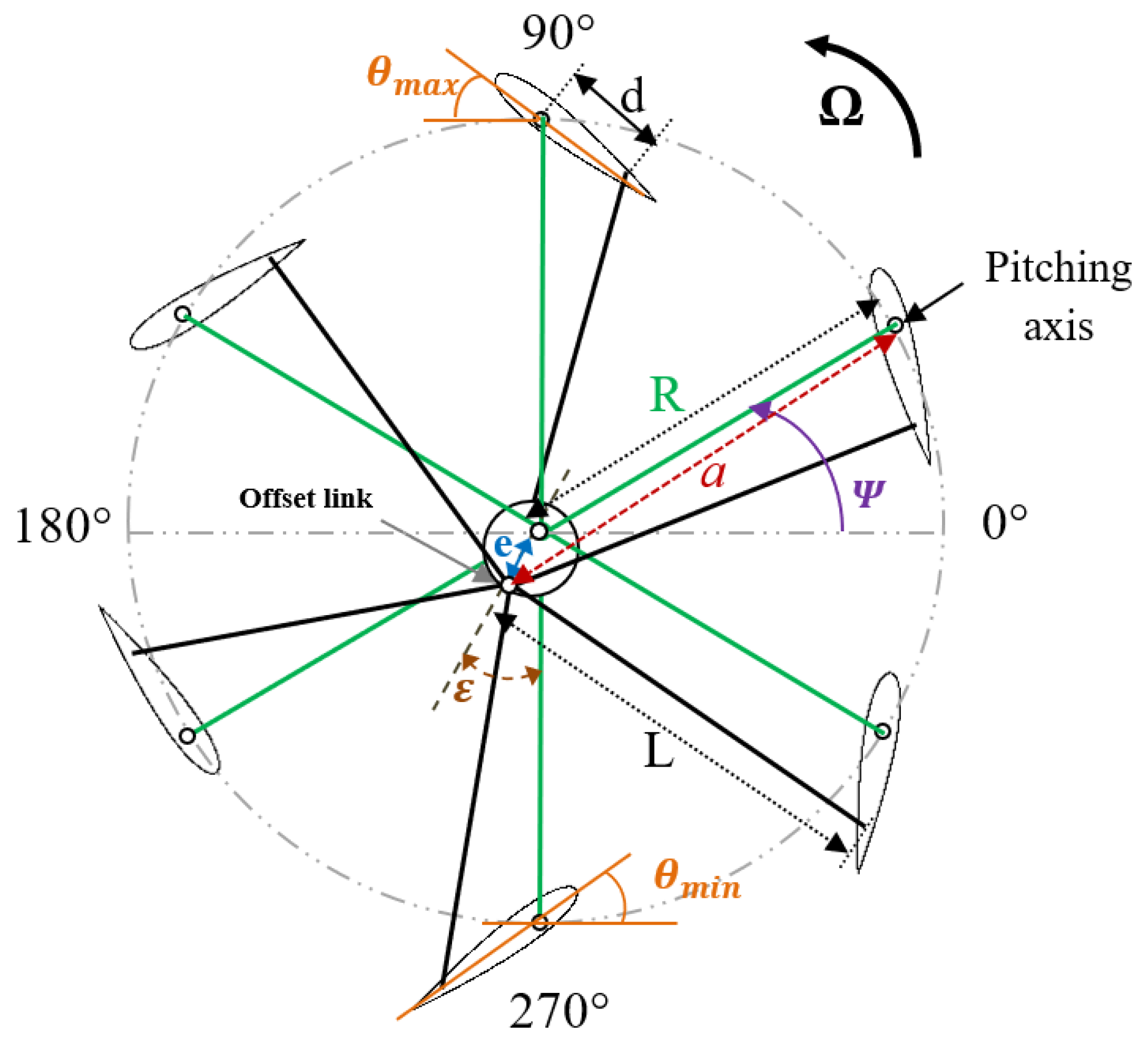
Figure 1. Kinematic system and blade’s pitch angle (θ) variation.
Actuators 12 00436 g001
Figure 2. Computational domain mesh.
Actuators 12 00436 g002
Figure 3. Schematic of the plasma body force.
Actuators 12 00436 g003
Figure 4. Mesh independence study.
Actuators 12 00436 g004
Figure 5. Result comparison of cycloidal rotor thrust as function of rotation speed of CFD model and experiments [81].
Actuators 12 00436 g005
Figure 6. (a) Modeled body force distribution; (b) velocity profile distribution in different positions, a comparison of CFD and Shyy data [66].
Actuators 12 00436 g006
Figure 7. Downwash velocity contour and streamlines around the cyclorotor blades at different times: (a) t = 1.92   s ; (b) t = 5.76   s ; (c) t = 9.6   s .
Actuators 12 00436 g007
Figure 8. Pressure coefficient contour of the cyclorotor blades at different azimuth positions during a complete revolution.
Actuators 12 00436 g008aActuators 12 00436 g008b
Figure 9. Lift coefficient and pitch angle variation of a cycloidal blade as a function of the azimuth angle.
Actuators 12 00436 g009
Figure 10. Induced velocity of the inner plasma actuator on a cyclorotor blade at Ψ = 240 ° in quiescent air.
Actuators 12 00436 g010
Figure 11. Vorticity contour comparison in different azimuth positions: (a) actuation off; (b) inner actuator on; (c) outer actuator on.
Actuators 12 00436 g011aActuators 12 00436 g011b
Figure 12. (a) Effect of plasma actuator side on the lift coefficient; (b) effect of combined control actuation.
Actuators 12 00436 g012
Figure 13. Effect of plasma actuator on the pressure contour distribution: (a) actuation off; (b) combined control actuation.
Actuators 12 00436 g013
Figure 14. Downwash velocity comparison: (a) actuation off; (b) combined control actuation.
Actuators 12 00436 g014
Figure 15. Effect of plasma actuation on the lift coefficient at different rotational speeds: (a) 200 rpm; (b) 100 rpm.
Actuators 12 00436 g015
Table 1. IAT21 L3 rotor parameters [81].
VariableValue
Profile NACA 0016
Number of blades 6
Rotor radius (R) 0.6 m
Chord (c) 0.3 m
Pitching axis 0.105 m
Control rod length (L)0.61 m
Magnitude of eccentricity (e)0.072 m
Eccentricity phase angle (ε)
Control rod distance (d)0.12 m
Pitching angle extremities ( θ m a x ,   θ m i n )36°; −39°
Disclaimer/Publisher’s Note: The statements, opinions and data contained in all publications are solely those of the individual author(s) and contributor(s) and not of MDPI and/or the editor(s). MDPI and/or the editor(s) disclaim responsibility for any injury to people or property resulting from any ideas, methods, instructions or products referred to in the content.