Abstract
The linkage mechanism of a cotton bundle fiber strength tester will have an unstable clamping force when clamping fiber bundle samples with uneven thickness, resulting in slippage or damage to the fibers increasing the pectin residue, leading to inaccurate test results and increased maintenance costs. To address this problem, according to the structural principle of the connecting rod-clamping mechanism, through the geometric relationship between the connecting rods to establish a parametric model of the mechanism and the use of the principle of virtual work on the mechanism to solve the force, the proposed new Dynamic Alternative Static Approximate Analysis Method (DASAAM) was based on Adams 2020. The Isight integrated Adams automatic optimization design framework was built. The variance of the change curve of the end force of the mechanism when clamping samples of different thicknesses was used as the evaluation function and the assembly conditions were used as the constraints. The dimensional parameters and angles of the mechanism were optimized using the multi-island genetic algorithm. The simulation results showed that when the thickness of the clamped sample varied in the range of 0–4 mm, the clamping force of the mechanism varied in the range of 8920–8630 N. Finally, the variance of the clamping force measured by the clamping force measurement component was 0.0367. The above results show that the DASAAM provided a new method for solving the static problem of mechanism morphological and position change, and the optimized linkage mechanism had better clamping force stability, which made the strength detection of cotton fiber more accurate, thus improving the quality of textile products.
1. Introduction
The specific strength at the break of cotton fibers is one of the most essential qualities of cotton and is measured by a bundle fiber strength meter. The testing process will first clamp the fiber at both ends of a certain length and then apply a tensile force parallel to the length direction of the sample until the fiber breaks. Generally, a flat fixture is used to clamp, but this method makes it easy to damage the fiber, i.e., clamping speed being too fast, which may directly cause fiber breakage. Typical cotton single-fiber or bunch-fiber manual fixtures comprise upper and lower grippers with a manual locking structure [1]. Spinlab introduced a breaker jaw system with hard plastic inserts that are not expected to wear as rapidly as leather. Still, these plastic components appear to become permanently grooved by repeated loading with the clamping jaws [2]. Spinlab’s system utilizes a cylinder linkage mechanism for automatic clamping.
When the thickness of the sample is not uniform, it is more likely to have problems of slippage and fiber surface wax (pectin) residue on the surface of the fixture, which ultimately leads to inaccurate test results. As part of the fixture, the elbow rod linkage mechanism is integral to the bundle fiber strength machine. At the same time, such mechanisms are widely used in automotive welding lines, injection molding machines, forging, and other scenarios. The leading performance indicators to measure the working performance of such mechanisms are the speed, stroke ratio, force amplification ratio, and efficacy coefficient [3,4,5,6,7]. Optimization of their operating parameters usually involves multiple design variables, analyzing and calculating the parameterized model using dynamics or statics, and using global search algorithms such as genetic algorithms to find the optimal solution. Shiakolas et al. studied four-bar mechanism synthesis by combining Differential Evolution, an evolutionary optimization scheme that can search outside the initially defined bounds for the design variables [8]. Lin and Hsiao proposed a new approach to design five-point double-toggle mechanisms and demonstrated the feasibility through a parametric study [9].
Isight TM was founded on the principle of interdigitation (Powell 1990), the combination of different classes of optimization algorithms to exploit the particular aspects of these algorithms is necessary to address specific aspects of a design problem [10]. Fei Tian et al. presented a detailed examination of the process and technology involved in hydraulic machinery optimization based on Isight 2021 software and its practical application [11]. In addition to the above-mentioned, Isight is widely used to optimize transplanting mechanisms, space landers, and bearings [12,13,14].
In recent years, a convolutional neural network (CNN), support vector machine (SVM), multiple Kernel support vector regression (MKSVR), genetic algorithm (GA), and other machine learning and deep learning algorithms have been widely used in fixture design, clamping force prediction, and mechanism optimization [15,16,17,18,19]. In W.Y. Lin’s work, the genetic algorithm with differential evolution (GA–DE) hybrid evolutionary algorithm and the real-valued genetic algorithm (RGA) with arithmetic crossover are employed to solve the optimization problem of the dimensional synthesis of the five-point double-toggle mold clamping mechanism with the performance of thrust saving for the prescribed input and output strokes [20]. GA is commonly used to optimize equipment designs, including T-tail structures, crane legs, layered mesh reinforced cylindrical shells, sandwich structure T joints, and satellite separation systems [21,22,23,24,25].
M. Shim and J.-H. Kim focused on the design of a special gripper for a wearable robot. A six-bar linkage incorporating a toggle mechanism is employed to reduce the overall weight of the gripper while maximizing the gripping force [26]. J.-Y. Chen et al. proposed a clamping force search methodology for determining the optimal clamping force setting of a hydraulic cylinder clamping injection molding machine in the processing of low-viscosity plastics such as thermoplastic polyurethane (TPU) and polypropylene (PP) [27]. Sumin Park et al. optimized the design of finger clamp units (FCU) so that individual FCUs were used for plates of different thicknesses. First, various linkage options were investigated to identify mechanisms that would be more useful for switching linkages. Second, the design was optimized to ensure a high clamping force over a predefined range of plate thicknesses. Validation experiments were conducted based on the simulation results. The proposed switching linkage mechanism is expected to be used for various clamping applications [28]. In the study by Y. Jeon et al, a new type of FCU was proposed with a compliant link that was compressed to adapt to various thicknesses of panels without additional calibration [29]. In the study by S. Kim et al., durability was improved by replacing the linear slide joint (the mechanical element of the FCU) with a curved slide joint from another study [30].
While most of the optimization studies of elbow-rod linkage fixtures focus on some of the more common operating parameters, the performance to be optimized for bundle fiber strength machines is the consistency of the clamping force when clamping samples of different thicknesses, since inconsistencies in the clamping force when clamping samples of cotton fibers of different thicknesses can result in either too much pressure damaging the fibers and increasing the pectin residue or too little force causing the test slippage phenomenon.
This paper presents a parametric model for the linkage mechanism, which is solved analytically using the principle of virtual work. A new computer-aided solution method called Dynamic Alternative Static Approximate Analysis Method (DASAAM) is proposed. The Isight integrated Adams framework was used to optimize the design of the linkage mechanism.
2. Research Methods
2.1. Structural Principle
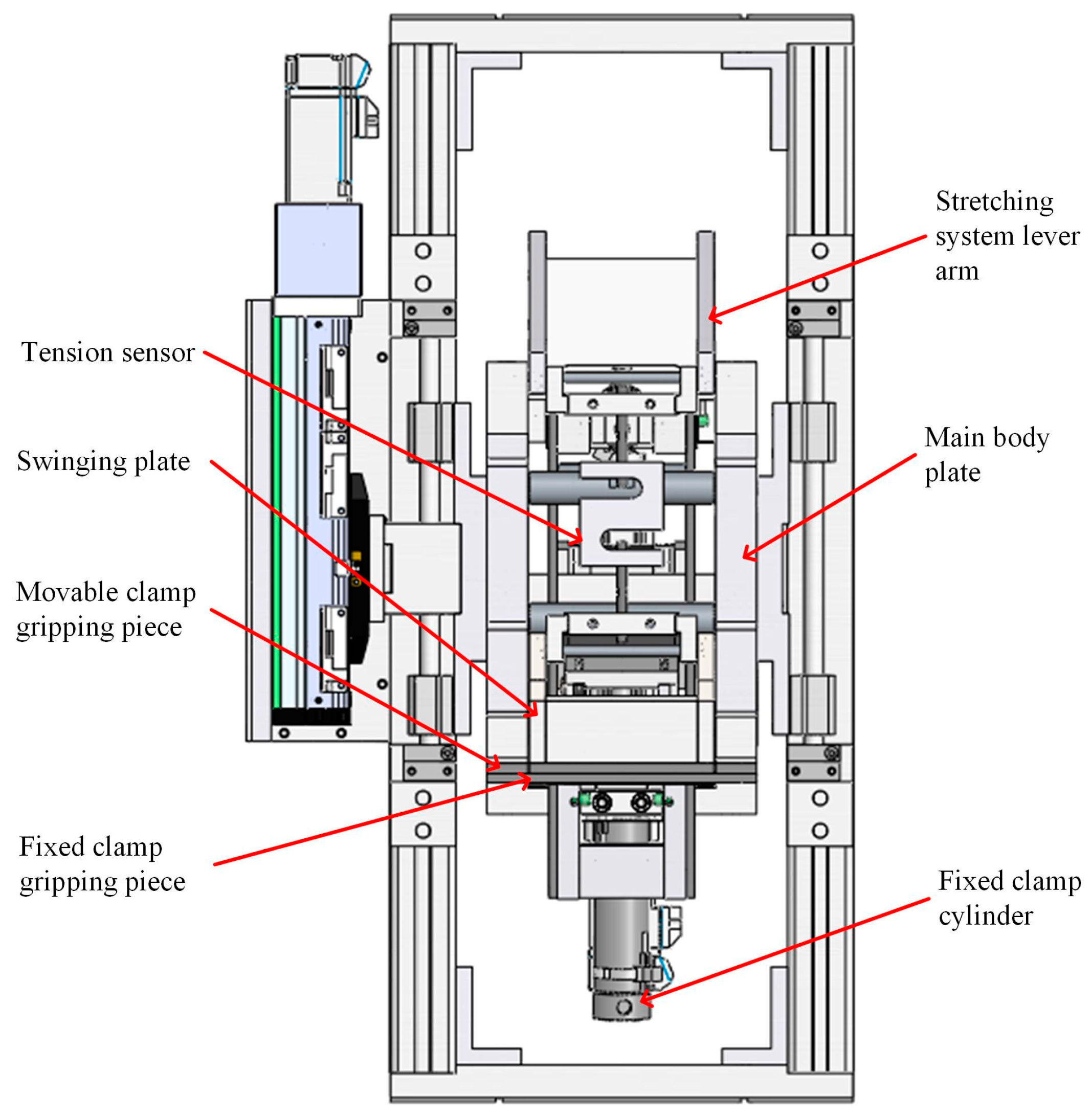
The bundle fiber strength machine, Figure 1, consisted of three parts of the mechanism: the fixed clamp mechanism, the movable clamp mechanism, and the stretching mechanism. This is shown in Figure 2 where the cylinder of the linkage mechanism, which can move with the swinging plate of the stretching mechanism, was hinged to the main body plate by trunnions. Its lower gripping piece could slide up and down along the outer end surface of the swinging plate, which was rotated by the stretching mechanism around the main body plate and cooperated with the upper gripping piece to realize the opening and closing of the clamp.
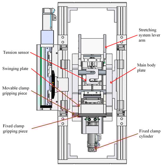
Figure 1.
Model of cotton bundle fiber strength testing device.
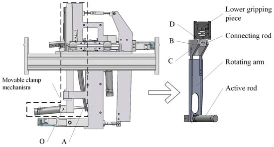
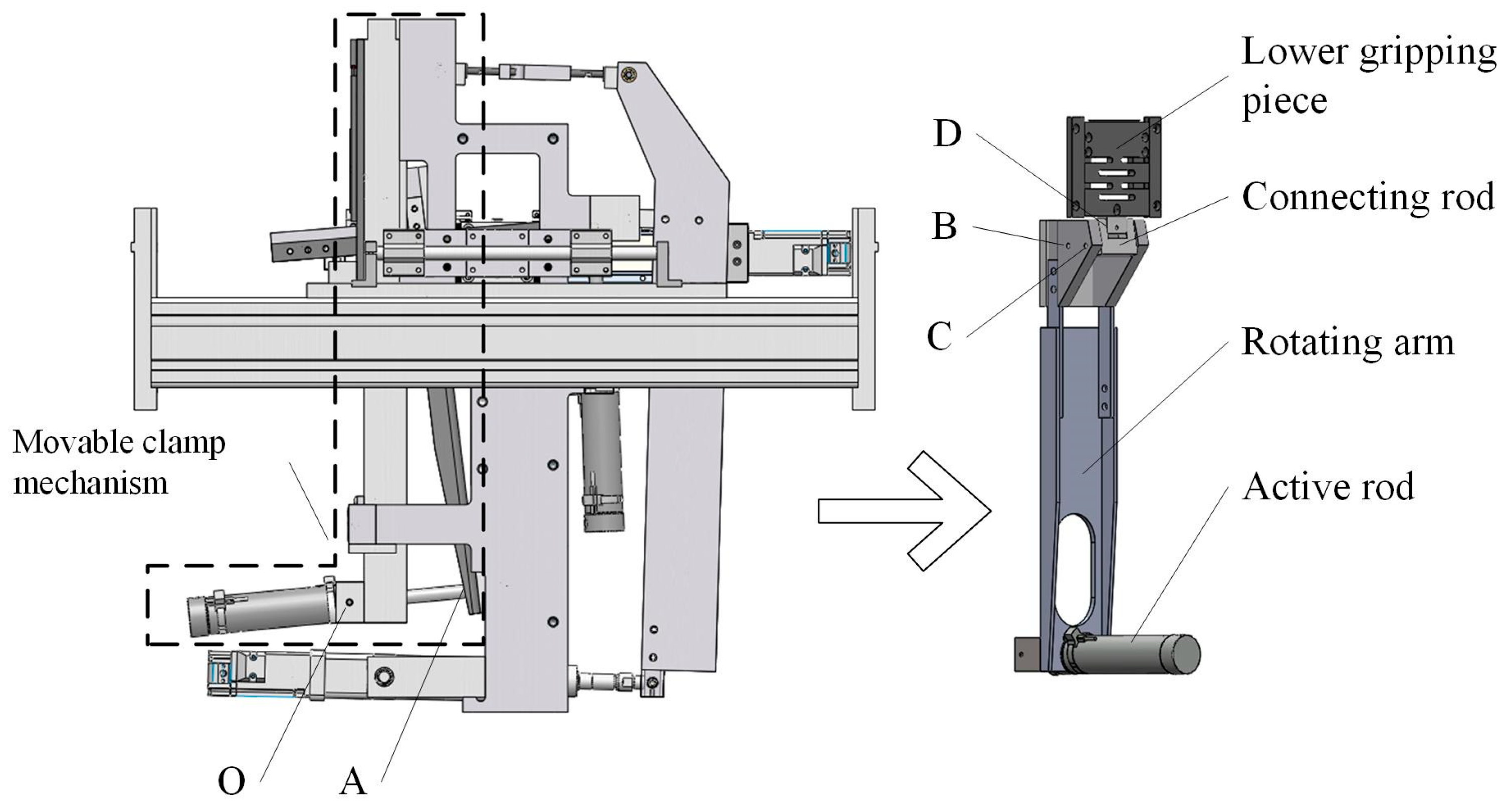
Figure 2.
Schematic diagram of the movable clamp mechanism position.
Figure 2 shows a structural view of the movable clamp mechanism, and Figure 3 shows a mechanical sketch. The fixed clamp was similar in structure to the movable clamp mechanism, so only the movable clamp mechanism was analyzed in this paper. The lower gripping piece, which slides up and down along the outer face of the swinging plate, was simplified as a slider. There were four components in the movable clamp mechanism: the active rod (cylinder), the rotating arm M, the connecting rod , and the lower gripping piece (slider) D. The rotating arm was a Revolute-Revolute-Revolute (RRR) rod, connecting rod was a Revolute-Revolute (RR) rod, the cylinder was a Revolute-Prismatic-Revolute (RPR) active rod, and the lower gripping piece was a Revolute-Prismatic (RP) rod. Seven low vices, i.e., five rotating pairs of O, A, B, C, and D in total, one moving pair of RP component slider D and the frame, and an RPR active rod , were regarded as an RR rod and an RP rod. Rod was considered as a combination of an RR rod member and an RP rod member with one rotation vice and one movement vice. So, the degree of freedom of the mechanism was 1. The only original moving part of the mechanism was the cylinder. The cylinder push rod provided the tension force, which made the RRR rod make the rotary motion. The number of original moving parts was equal to the degree of freedom, and the motion of the whole mechanism was determined. When the cylinder worked, the push rod contracted and drove the rotating arm M to rotate around point B. Slider D moved upward along the track and cooperated with the upper gripping piece fixed on the main frame to complete the closure, and the distance moved upward by Slider D was ∆S.

Figure 3.
Clamping mechanism analysis sketch.
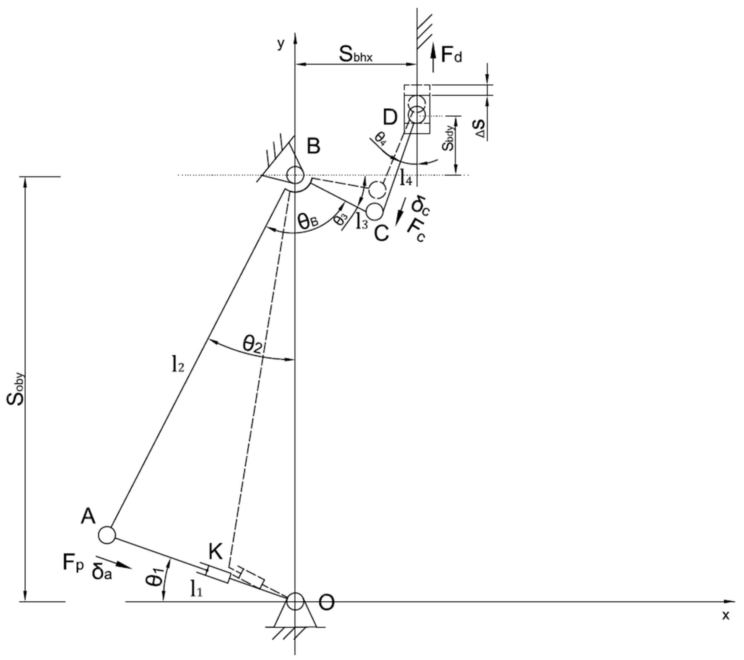
2.2. Mechanism Parameterized Model
A coordinate system was established with O as the origin, as the length of the active rod OA, as the length of the lower-end AB of the rotating arm, as the length of the upper-end BC of the rotating arm, as the length of the connecting rod CD, and as the distance between point A and point C. When the distance between the solid joint of the mechanism and the frame was changed, various configurations were produced. In addition to the swing direction of each linkage of the mechanism, different morphological schemes were also formed. Still, with equivalent calculation formulas and results, only the morphological arrangement scheme shown in Figure 3 was selected. O and B had the same transverse coordinates, and the distance between OB was the fixed value , and B and D in the direction of the x-axis was the fixed value . The angle at which the rotating arm opened, i.e., angle ABC, was , and was the angle between rod AB and the y-axis.
Through the trigonometric cosine theorem or loop equation, we found:
From this, we calculated the coordinates of point A and the . Through the coordinate equation and azimuth, we found the coordinate expression of point C. The coordinate expression of point C was:
From the geometric relationships in the parameterized model, the coordinates of A, B, K, and D were obtained as follows:
After establishing the above-parameterized model of the moving nozzle, it was easy to generate the model after the parameter change by only changing the length of each rod and solving and analyzing the model on this basis.
2.3. Solving Static Equilibrium Using the Principle of Virtual Displacement in Analytical Mechanics
In order to address the relationship between the cylinder’s thrust and the pressure side of the end clamping piece in static equilibrium, generalized coordinates were introduced to describe the position of the force action point. The three parameters introduced were , , and , and they were not independent. Due to the degree of freedom of the system being 1, the parameter that describes the system’s positional shape was only needed for 1, but retaining the extra generalized coordinates could simplify the expression. The clamping piece force point was point D, the cylinder tension point was point A, the rod CD was a two-force rod, point C and point D had the same magnitude of force, and the direction was opposite. Point C was analyzed to find the situation at point D. The virtual displacement of point C in the direction of the x and y axes were and , and the virtual displacement component of point A in the x and y axes were and , respectively.
From Figure 5, the x and y coordinates of point C satisfied the following constraint Equations (6) and (7):
The value of the plus and minus sign was determined by the position at which the connecting rod was located. The constraint Equations (8) and (9) were satisfied by point A’s x and y coordinates, respectively.
The imaginary displacement was an infinitesimal displacement allowed by the constraint, and the x-coordinate of point C still satisfied the constraint after adding the imaginary displacement.
After expanding Equation (10) at one point in terms of the Taylor series, and neglecting higher order minimizers of the second order and above, we had:
Subject to:
So:
From Equation (13):
i.e.,
Similarly:
According to the principle of virtual work, there were:
The force at point C was , and the tension in the cylinder was . From Equation (19), there were:
Subject to:
So:
Equation (22) gives the relationship between and :
The angular parameters in Equation (23) were calculated from the coordinates of the points.
Finally, through Equation (28), we calculated the:
2.4. Optimization Variables, Objective Function, and Constraints
Considering the influence of the rod size on the linkage gripper configuration and performance indexes, the lengths , , , and of each member and the angle of the rotating arm, , were taken as the parameter variables for optimization. Min-max normalization was performed by Equation (29). Equation (30) is the formula for variance calculation.
In Equation (29), was the clamping force before normalization, was the clamping force after normalization, and was the maximum value of the clamping force curve data. The same was the minimum value. Equation (30) was the average value of the normalized clamping force curve data, and Q was the variance value.
The constraints on the variables were as follows:
Equations (31) and (32) were both constraints set to satisfy the assembly conditions. When the equals sign was taken, the two members overlapped or were co-linear and could not be assembled without satisfying the constraints.
2.5. Dynamic Alternative Static Approximate Analysis Method
The process of solving the static equilibrium of a mechanism is very cumbersome, especially when exploring the static equilibrium of the mechanism in the particular case of change of form and position. The variation of clamping force when clamping samples or workpieces with different thicknesses contributes to this problem. A method for solving the static equilibrium of a mechanism during the change of its morphology and position using a computer dynamics simulation software called the Dynamic Alternative Static Approximate Analysis Method (DASAAM), was proposed here. Figure 4 shows the Adams template file.
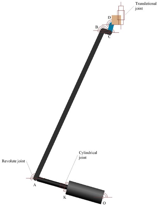
Figure 4.
Adams model of clamping linkage mechanism.
The operation was performed by setting the mass and moment of inertia of all components except the components to be analyzed for end forces to a minimal value, while the end force components to be analyzed were set to a larger mass. The inertia forces were negligible at this point, and the dynamic response was much smaller than the static equilibrium. From the theoretical point of view, due to the mass of other components on the final force member of the influence of the small, and because the final force member of the larger mass, the mechanism at a certain point in time was approximated as a static state of motion. The results of the dynamics of the results and the results of the static analysis were very close.
2.6. Feasibility Testing
To verify the method’s feasibility, the static equilibrium solution results of the two positions were selected to compare with the DASAAM, and the coordinates were also calculated using the coordinate orthogonal formula and azimuthal angle. The coordinates of point C were first found out through the known coordinates of points B and D, and then the coordinates of point A were found from B and C. The coordinates of each point at the two positions are shown in Table 1. , , , and were the values of the horizontal and vertical coordinates of each design point at the initial position and when the gripper sheet moved to the position = 381.25, respectively.

Table 1.
Coordinates of each parameter point at the validation position.
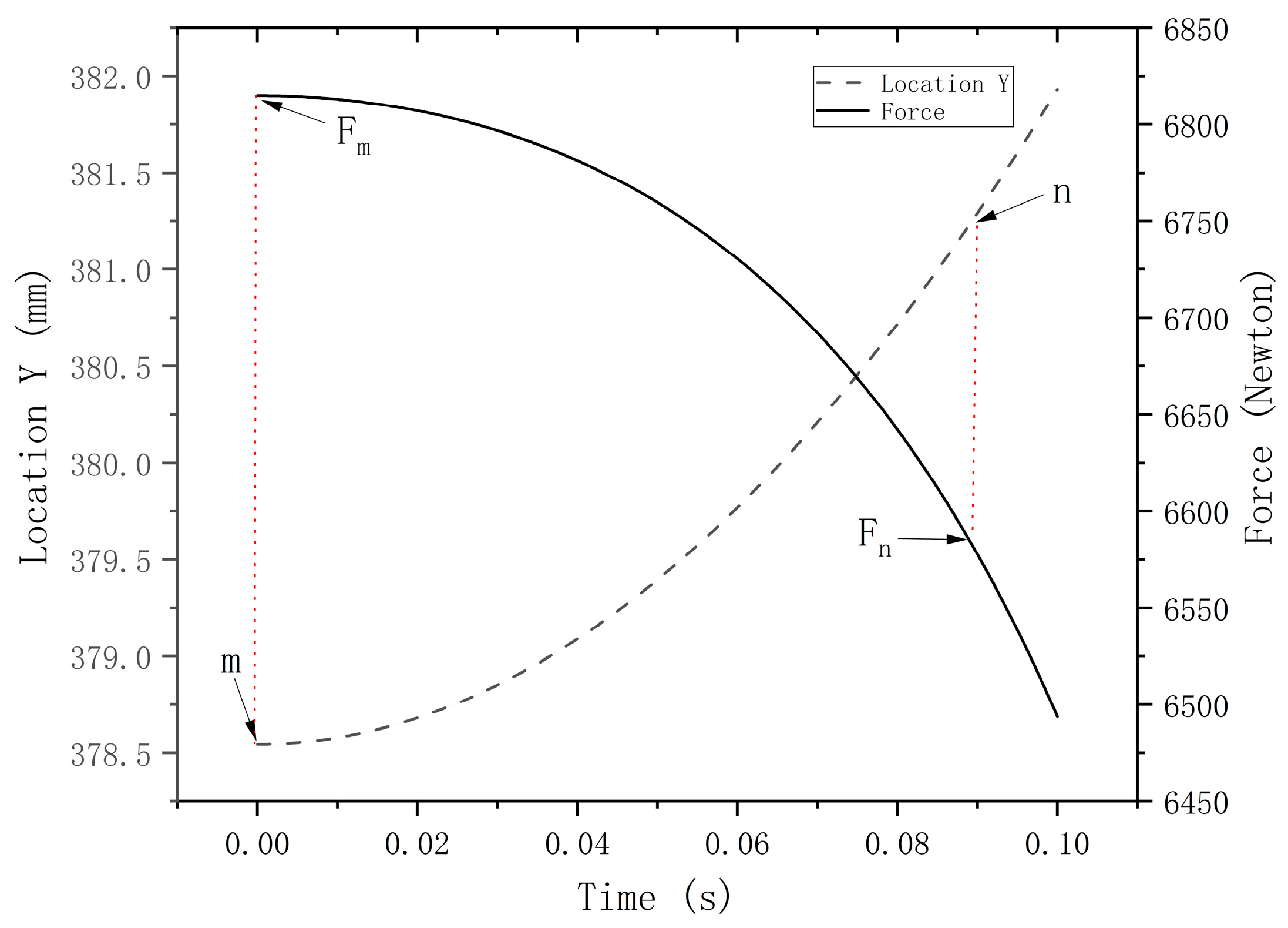
Figure 5 shows the results obtained by using the DASAAM to analyze the elbow rod linkage mechanism. The initial position m of the clamping piece of the force size of 6814.92 N by the Equation (28) static equilibrium calculated of the results of 6814.92 N, in the clamping piece of the movement to the position of = 381.25 of the position n when 6581.99 N. The result of the calculation was 6581.99 N, and the result of the DASAAM was consistent with the static equilibrium, which showed that this method can be used to solve the static equilibrium solution problem in the process of the change of the mechanism’s morphological position.
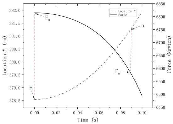
Figure 5.
Results of the static force solution for the selected position.
2.7. Isight Integration Adams Framework Build
To achieve the optimal combination of parameters, simplify calculations, and prevent calculation errors, the Isight platform was employed to integrate the Adams method. This integration aimed to optimize the performance of the end clamp, maintaining a stable clamping force when clamping samples of different thicknesses. The following files were needed in the process of applying Isight to the optimization design: input file, output file, application startup file, and model file. The optimization framework built is shown in Figure 6.
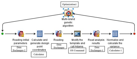
Figure 6.
Isight integration with Adams optimization framework.
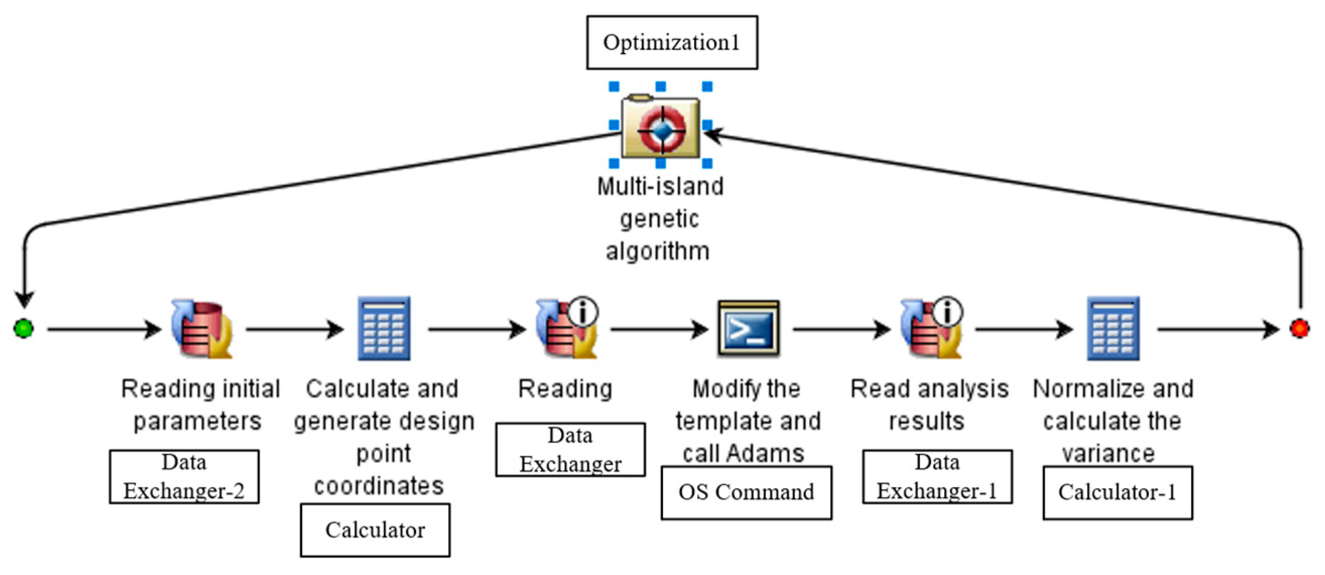
2.8. Overall Optimized Flow Chart
The optimization process is shown in Figure 7. When Isight’s process component optimization1 optimization algorithm generated parameters, the application component Calculator read the parameters through Data Exchanger-2 and calculated the parameterized coordinates of each point. The Data Exchanger wrote the parameterized coordinates of each point into the template through the Adams macro command script and generated the model, OS. The command component called Adams automatically performed simulation calculations. Data Exchanger-1 read the calculated results, whilst Calculator-1 calculated the standard deviation and returned the results to the optimization component to evaluate the fitness of the set of parameters. If an error occurred, the correspondence of the data flow needed to be changed manually.
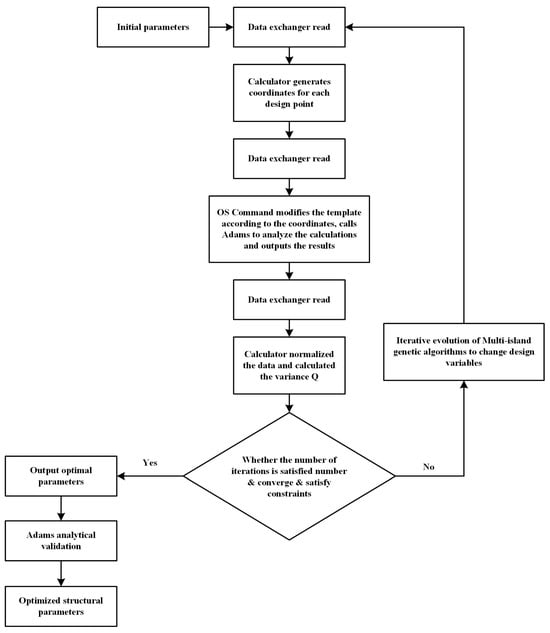
Figure 7.
Optimization flowchart.
2.9. Variable Value Range Setting
The purpose of setting the value range of the variables was twofold. Firstly, to consider the mechanical properties of the material of the mechanism and the processing and manufacturing requirements to set the size to achieve the expected design performance. Secondly, to limit the spatial dimension size of the mechanism to avoid the overall size of the mechanism being too large or too small. Table 2 shows the range of values of the design variables in the optimization model. The active rod’s thrust was set to 394.86 N.
Table 2.
Range of values for each design variable parameter.
The setup steps for the Optimization component were: enter the range of values for these parameters in the Variable menu bar, then select the standard deviation Q as the optimization variable in the Objective menu bar and set the objective direction of its optimization variable to a minimum.
2.10. Algorithm Selection and Parameterization
The stability of the clamping force of the mechanism is a nonlinear combinatorial optimization problem. This type of problem generally uses genetic algorithms to find the optimal solution. Here, the choice was the built-in multi-island genetic algorithm in Isight.
Classical genetic algorithms have better global search performance due to population search characteristics. They have higher efficiency than traditional optimization algorithms such as analytic methods, random search methods, and exhaustive methods in dealing with some complex system optimization problems. Still, they also have the shortcomings of falling into the local optimal solution prematurely and having low local convergence accuracy. The multi-island genetic algorithm is a variant of the genetic algorithm, which differs from the ordinary genetic algorithm in that the population is divided into multiple islands (subpopulations) in the multi-island genetic algorithm. Each island evolves independently and maintains gene exchange between islands through migration operations. The algorithm parameters were selected as shown in Table 3.
Table 3.
Multi-island genetic algorithm parameterization.
3. Experiment Setup
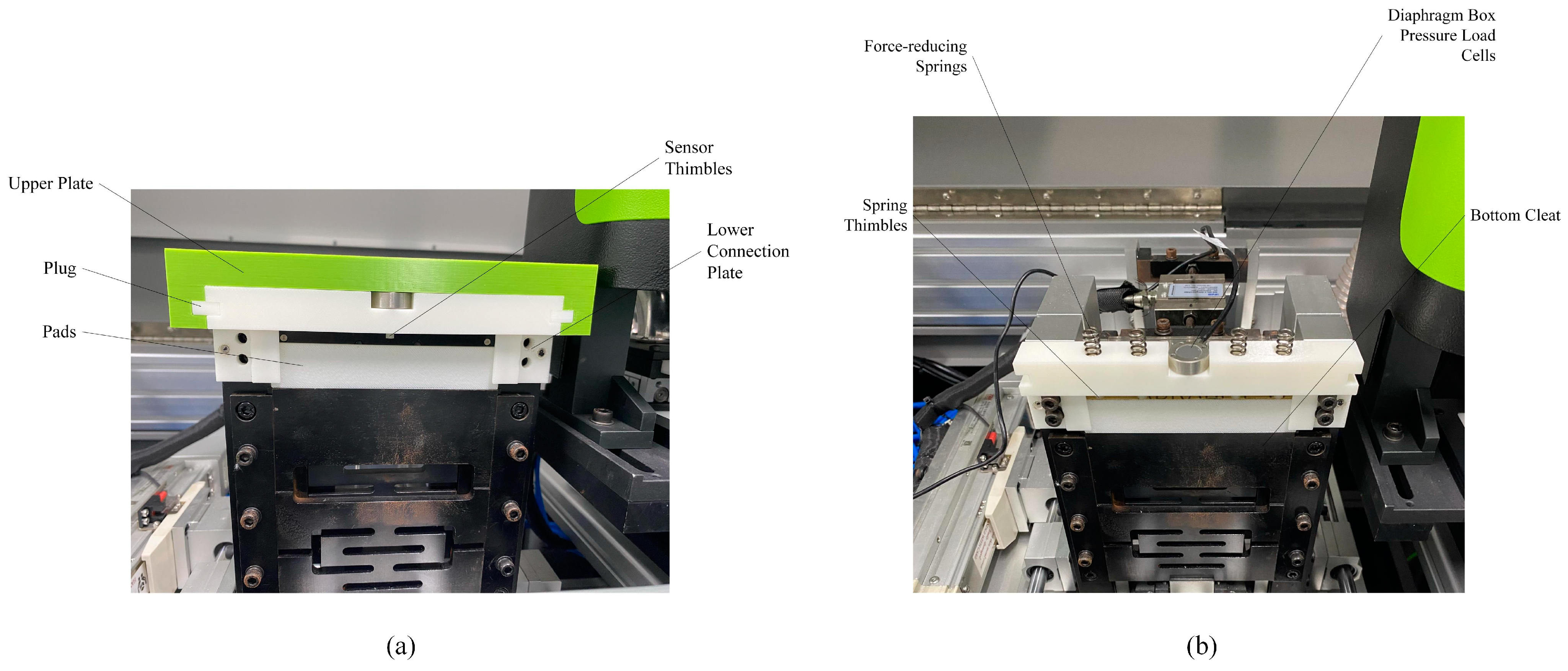
After the above design and optimization search process, we determined the optimal rod length and dimensional parameter. In order to verify the reliability of the design, a clamping pressure measuring device was installed on the bundled fiber strength testing device. This testing device was manufactured according to the exact dimensions of the clamping mechanism described in the optimized design above. The test setup is shown in Figure 8.

Figure 8.
(a) External structure of the clamping force measuring device. (b) Internal structure of the clamping force measuring device.
The experiment used sensor thimbles and spring thimbles of varying lengths to measure the change in clamping force when the position of the clamping piece was altered. The clamping piece was moved upwards by 0.5 mm increments until it reached 4 mm, using nine groups of sensor and spring thimbles with different lengths. Pressure sensors recorded data 9 times at different positions of the clamping piece, and thimbles of varying lengths were replaced after each test. This method allowed the researchers to obtain the variation of clamping force at different positions and calculate its variance.
4. Results and Discussion
4.1. Optimization Results Analysis
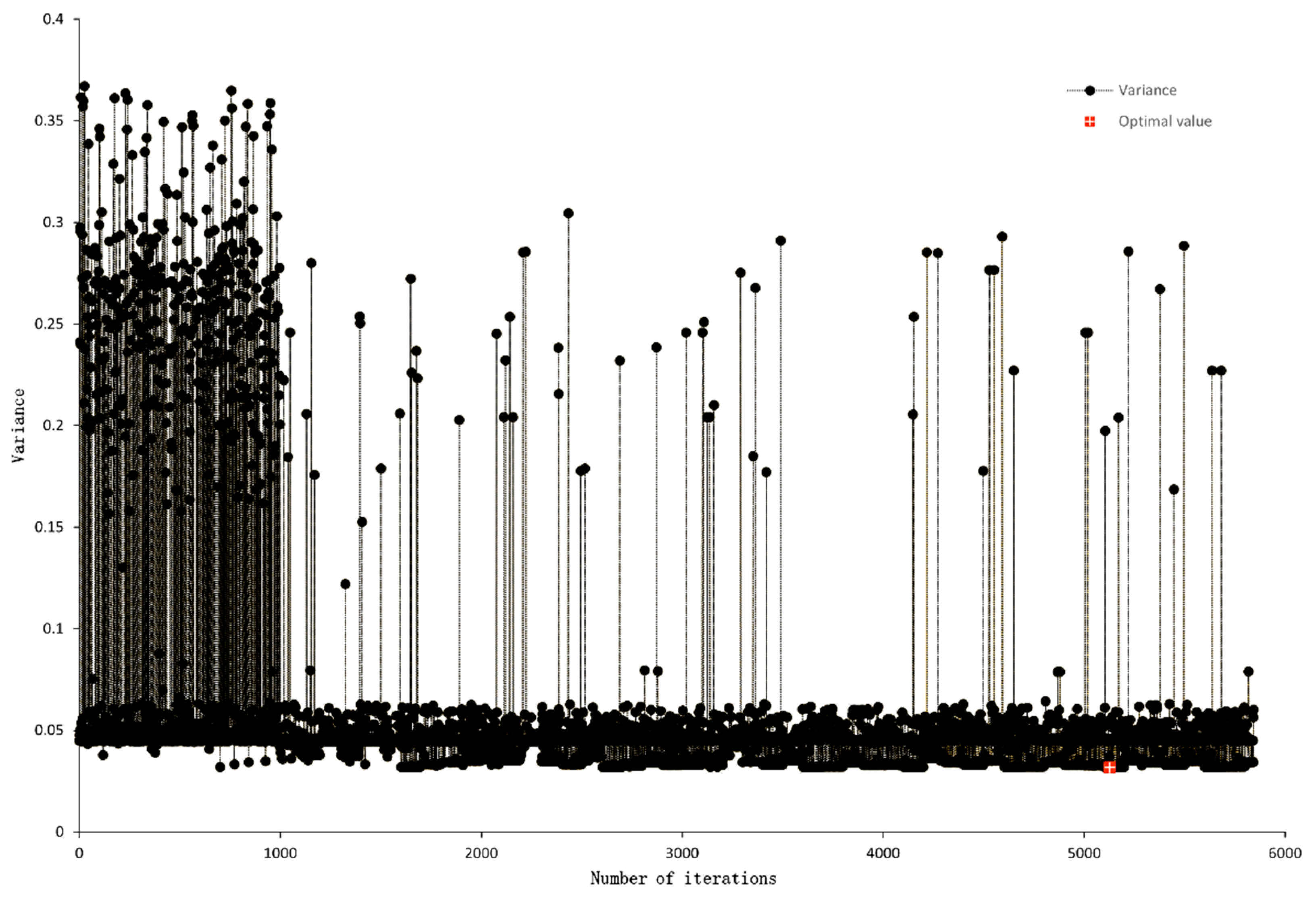
The optimization process was carried out with a total of 5800 iterations of calculation. The optimal size and angle generated as shown in Table 4. The degree of influence of each design variable on the objective function is shown in Figure 9 where , , and harmed the stability of the clamping force, i.e., the smaller , , and the better the stability of the clamping force was. However, the effect of on stability was very low, had a large negative effect influence, greater than . Both and had some positive impact on the stability of the clamping force. Figure 10 shows the trend of the objective function with the red-marked point being the optimal solution of the objective function.
Table 4.
Optimal results for design variables.
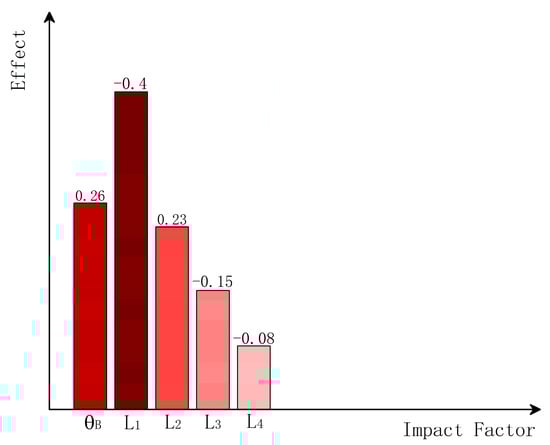
Figure 9.
Effect of factors on clamping force uniformity.
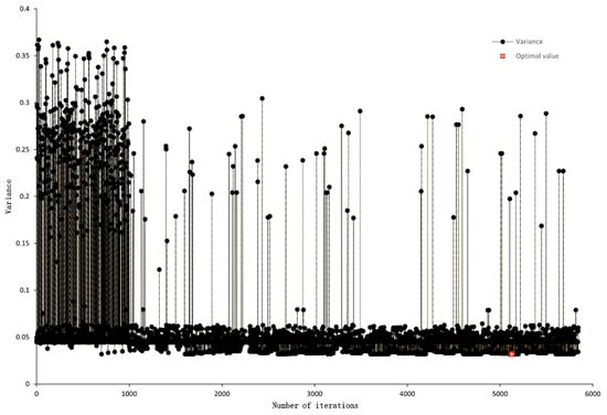
Figure 10.
Multi-island genetic algorithm evolutionary optimization history.
The optimization process of the end clamping static force curve of the mechanism is shown in Figure 10. In the figure, the variance of the objective function fluctuated significantly at the beginning. The algorithm gradually converged when approaching the 1000th generation. Still, to avoid falling into the local optimal solution, the algorithm communicated genes between the “islands” in the process of evolutionary iteration, which is also the reason for the local fluctuation of the algorithm even though the algorithm had already converged in the vicinity of the optimal solution. The minimum variance was 0.0318 at the 5127th iteration.
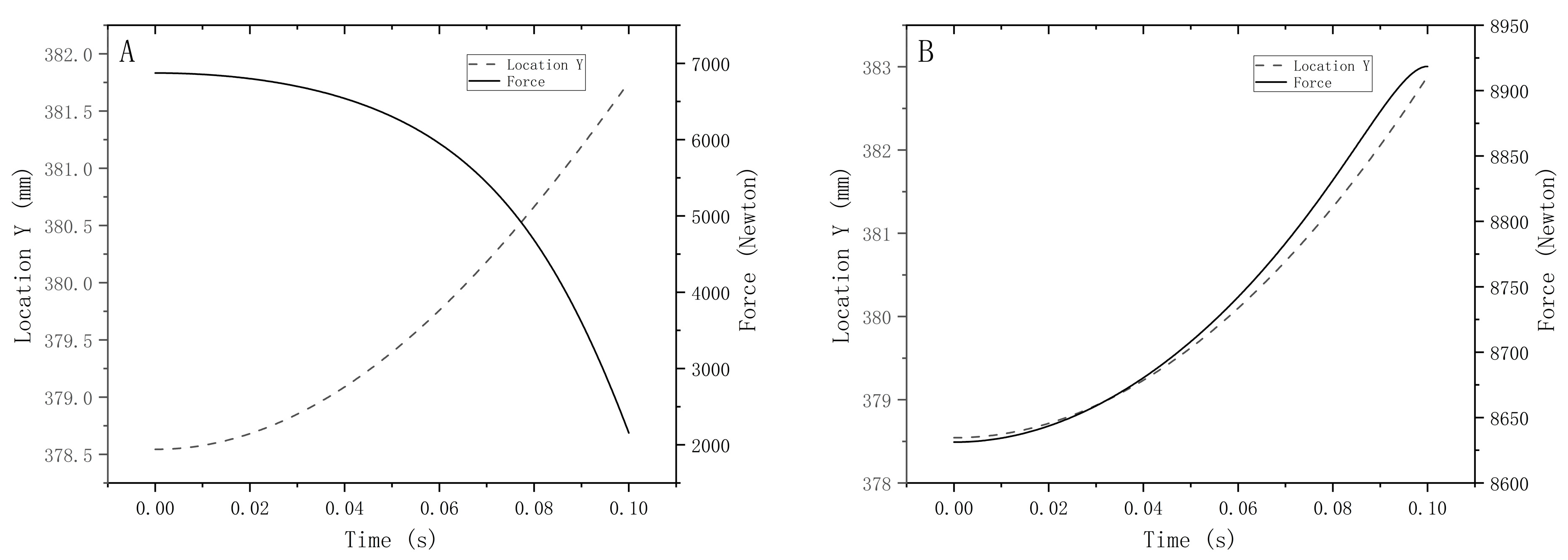
The curves of the force at the end of the mechanism generated by the parameters obtained from the optimization search as a function of the morphological position of the mechanism are shown in Figure 11B. The clamping force varied from 8920 to 8630 N when the sample thickness varied within the 0–4 mm range, using the mechanism generated with this size and angle parameter. The clamping force increased slightly with increased sample thickness when clamping samples of different thicknesses.
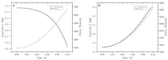
Figure 11.
Mechanism clamping force plots of (A) Curve of fixture clamping force versus position for initial parameters (B) Optimized mechanism clamping force versus position curve.
It was optimized to look good, but no dynamics theory explained why the DASAAM was feasible. Hence, the setting of the mass was critical. The set of the mass was related to the distance of the end actuator movement of the mechanism after the cylinder applied the pull force, which significantly impacted the correctness of the optimization results. When the end-slider mass was set too large, the range of variation in position was small, but the error became more prominent if it was too small. Although the method had some limitations, it still provided a simpler computer-aided calculation method for solving the continuous static force solution while changing the linkage mechanism form position.
4.2. Experimental Result
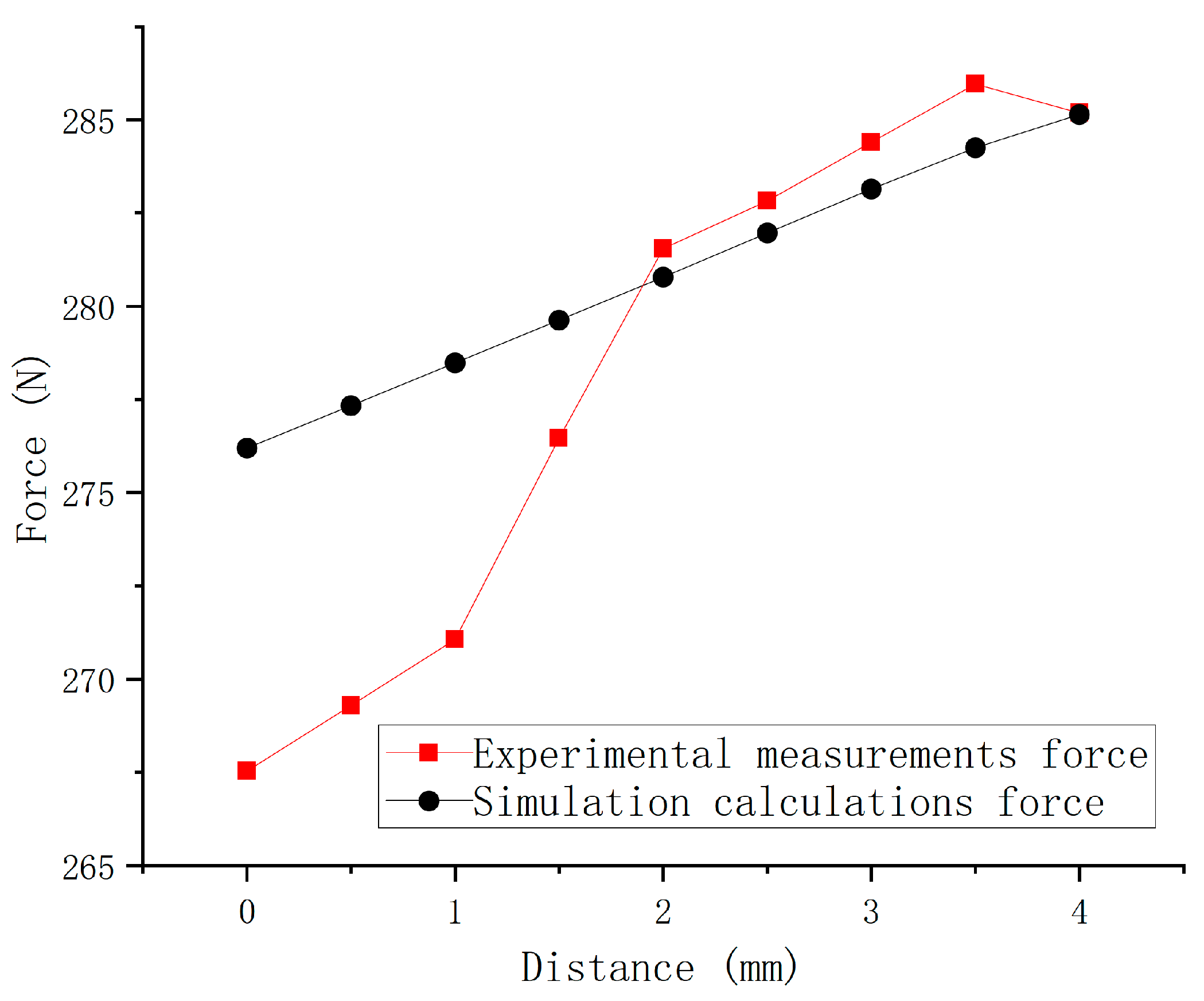
The test was carried out on 19 September 2023, in Room 322, School of Mechanical and Electrical Engineering, Shihezi University, and the measuring assembly consisted of a HYMH-018 diaphragm box pressure load cell (range: 0–30 kg), upper cover plate, connecting plate, pins, pads, force-reducing springs, transducer thimbles, and spring thimbles. The inner diameter of the connecting rod cylinder was 27 mm, and the given air pressure was 0.05 Mpa. The results are shown in Figure 12. After normalization, the variance was found to be 0.0367. There was an error between the actual measurements and the simulation calculations, and the variance of the experiment was slightly higher than the simulation results. Regarding the issue that the consistency of the clamping force in the actual test was somewhat lower than in the simulation test, this was due to friction between moving parts and assembly errors.
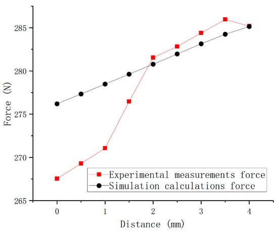
Figure 12.
Relationship between clamping force and clamping plate position.
5. Conclusions
A parametric model of the elbow rod linkage mechanism was established through geometrical relations, the degrees of freedom were analyzed, and the relational Equation between the input and end output forces was derived using the principle of virtual work.
A Dynamic Alternative Static Approximate Analysis Method (DASAAM) was proposed, and the method’s feasibility was proved after two positions were selected for actual checking. The process provided a new approach for solving the static force solution problem during the continuous change of mechanism morphology and location.
The linkage clamping mechanism was optimized and designed using the automatic optimization design framework and multi-island genetic algorithm. The objective function was the stability of the end clamping force, with four dimensions and one angle as the design variables, and the final variance of the clamping force fluctuation was 0.0318. The variance of the experimental results was 0.0367, which was slightly higher than the simulation results. The optimized linkage mechanism had better-clamping force stability, which made the strength detection of cotton fiber more accurate.
Author Contributions
Conceptualization, D.J.; Methodology, D.J. and H.W.; Software, D.J.; Validation, H.L.; Resources, H.W. and R.Z.; Data curation, R.H.; Writing—original draft, D.J.; Writing—review & editing, R.Z. and H.L.; Supervision, H.W. and R.H.; Project administration, H.W. All authors have read and agreed to the published version of the manuscript.
Funding
This research was funded by the National Key R&D Plan of China (2022YFD2002400), the Science and Technology Bureau of Xinjiang Production and Construction Corps (2023AB014, 2022DB003), the Science and Technology Planning Project of the 12th Division of Xinjiang Production and Construction Corps (SRS2022011), and the Science and Technology Planning Project of the 7th Division of Xinjiang Production and Construction Corps (QS2022005).
Data Availability Statement
All data for this study have been included in this paper and there are no other unpublished data.
Acknowledgments
We express our gratitude to Chengzhi Wang from Jimei University for generously providing us with the Computer-Aided Design for Mechanism (MCad) software, which greatly facilitated our study.
Conflicts of Interest
The authors declare no conflict of interest.
References
- Elmogahzy, Y.; Farag, R. Tensile properties of cotton fibers. In Handbook of Properties of Textile and Technical Fibres; Woodhead Publishing: Sawston, UK, 2018; pp. 223–273. [Google Scholar]
- Taylor, R.A. Cotton Tenacity Measurements with High Speed Instruments. Text. Res. J. 1985, 56, 92–101. [Google Scholar] [CrossRef]
- Gawande, S.H.; Bhojane, S.A. Numerical and Experimental Design Optimization of Toggle Clamping Mechanism. Iran. J. Sci. Technol. Trans. Mech. Eng. 2018, 43, 763–779. [Google Scholar] [CrossRef]
- Hsieh, L.-C.; Chen, T.-H.; Lai, P.-C. The kinematic design of mold clamping mechanism with minimal maximum acceleration. Adv. Mech. Eng. 2020, 12, 1687814020926280. [Google Scholar] [CrossRef]
- Hsieh, L.C.; Chen, T.H.; Lai, P.C.; Zheng, S.W. Optimal design on Watt-chain double-toggle mold clamping mechanism for injection molding machine. Sci. Prog. 2021, 104, 368504211041488. [Google Scholar] [CrossRef] [PubMed]
- Huang, M.-S.; Lin, T.-Y.; Fung, R.-F. Key design parameters and optimal design of a five-point double-toggle clamping mechanism. Appl. Math. Model. 2011, 35, 4304–4320. [Google Scholar] [CrossRef]
- Yossifon, S.; Shivpuri, R. Analysis and comparison of selected rotary linkage drives for mechanical presses. Int. J. Mach. Tools Manuf. 1993, 33, 175–192. [Google Scholar] [CrossRef]
- Shiakolas, P.S.; Koladiya, D.; Kebrle, J. On the Optimum Synthesis of Four-bar Linkages Using Differential Evolution and the Geometric Centroid of Precision Positions. Inverse Probl. Eng. 2002, 10, 485–502. [Google Scholar] [CrossRef]
- Lin, W.Y.; Hsiao, K.M. Study on improvements of the five-point double-toggle mould clamping mechanism. Proc. Inst. Mech. Eng. Part C J. Mech. Eng. Sci. 2016, 218, 761–774. [Google Scholar] [CrossRef]
- Koch, P.N.; Evans, J.P.; Powell, D. Interdigitation for effective design space exploration using iSIGHT. Struct. Multidiscip. Optim. 2014, 23, 111–126. [Google Scholar] [CrossRef]
- Tian, F.; Yang, C.; Zhang, E.; Sun, D.; Shi, W.; Chen, Y. Design Optimization of Hydraulic Machinery Based on ISIGHT Software: A Review of Methods and Applications. Water 2023, 15, 2100. [Google Scholar] [CrossRef]
- Li, A.; Wang, C.J. Construction of Lander Multidisciplinary Optimization Platform. Key Eng. Mater. 2009, 407, 180–184. [Google Scholar] [CrossRef]
- Tingting, C.; Dequan, Z.; Wei, X.; Lin, Z.; Shun, Z.; Tien-Chien, J.; Juan, L. Optimizing Transplanting Mechanism with Planetary Elliptic Gears Based on Multi-body Dynamic Analysis and Approximate Models. Procedia Manuf. 2019, 35, 1356–1362. [Google Scholar] [CrossRef]
- Wang, C.L.; Zeng, Q.L.; Han, R.J.; Ren, L. Multidisciplinary Design Optimization Method and Algorithm Based on iSIGHT. Adv. Mater. Res. 2011, 284, 962–965. [Google Scholar] [CrossRef]
- Liu, Z.H.; Wang, M.Y.; Wang, K.D.; Mei, X.S. Fixture performance improvement by an accelerated integral method of fixture layout and clamping force plan. Proc. Inst. Mech. Eng. Part B-J. Eng. Manuf. 2013, 227, 1819–1829. [Google Scholar] [CrossRef]
- Li, E.; Zhou, J.; Yang, C.; Wang, M.; Li, Z.; Zhang, H.; Jiang, T. CNN-GRU network-based force prediction approach for variable working condition milling clamping points of deformable parts. Int. J. Adv. Manuf. Technol. 2022, 119, 7843–7863. [Google Scholar] [CrossRef]
- Hamedi, M. On application of machine learning in fixture design and clamping optimization. In Proceedings of the 2005 IEEE International Conference on Mechatronics and Automations, Niagara Falls, ON, Canada, 29 July–1 August 2005; pp. 1562–1568. [Google Scholar]
- Cao, E.H.; Su, J.H.; Liu, Z.Y.; Qiao, H. Development of a New Model for the Fixture Design and Clamping Optimization. In Proceedings of the 2014 11th World Congress on Intelligent Control and Automation (WCICA), Shenyang, China, 29 June–4 July 2014; pp. 359–364. [Google Scholar]
- Vasundara, M.; Padmanaban, K.P. Recent developments on machining fixture layout design, analysis, and optimization using finite element method and evolutionary techniques. Int. J. Adv. Manuf. Technol. 2014, 70, 79–96. [Google Scholar] [CrossRef]
- Lin, W.Y.; Wang, S.S. Dimensional synthesis of a five-point double-toggle mould clamping mechanism using a genetic algorithm—Differential evolution hybrid algorithm. Proc. Inst. Mech. Eng. Part C J. Mech. Eng. Sci. 2010, 224, 1305–1313. [Google Scholar] [CrossRef]
- Hu, X.; Chen, X.; Zhao, Y.; Yao, W. Optimization design of satellite separation systems based on Multi-Island Genetic Algorithm. Adv. Space Res. 2014, 53, 870–876. [Google Scholar] [CrossRef]
- Liu, Z.-H.; Tian, S.-L.; Zeng, Q.-L.; Gao, K.-D.; Cui, X.-L.; Wang, C.-L. Optimization design of curved outrigger structure based on buckling analysis and multi-island genetic algorithm. Sci. Prog. 2021, 104, 00368504211023277. [Google Scholar] [CrossRef]
- Niu, Y.; Xu, X.; Guo, S. Structural Optimization Design of a Typical Adhesive Bonded Honeycomb-Core Sandwich T-joint in Side Bending Using Multi-Island Genetic Algorithm. Appl. Compos. Mater. 2021, 28, 1039–1066. [Google Scholar] [CrossRef]
- Qiu, J.; Sun, Q. Structural optimization technique of a T-tail. Proc. Inst. Mech. Eng. Part G J. Aerosp. Eng. 2012, 227, 1009–1020. [Google Scholar] [CrossRef]
- Zhao, Y.; Chen, M.; Yang, F.; Zhang, L.; Fang, D. Optimal design of hierarchical grid-stiffened cylindrical shell structures based on linear buckling and nonlinear collapse analyses. Thin-Walled Struct. 2017, 119, 315–323. [Google Scholar] [CrossRef]
- Shim, M.; Kim, J.-H. Design and optimization of a robotic gripper for the FEM assembly process of vehicles. Mech. Mach. Theory 2018, 129, 1–16. [Google Scholar] [CrossRef]
- Chen, J.-Y.; Yang, K.-J.; Huang, M.-S. Optimization of clamping force for low-viscosity polymer injection molding. Polym. Test. 2020, 90, 106700. [Google Scholar] [CrossRef]
- Park, S.; Bae, J.; Jeon, Y.; Chu, K.; Bak, J.; Seo, T.; Kim, J. Optimal design of toggle-linkage mechanism for clamping applications. Mech. Mach. Theory 2018, 120, 203–212. [Google Scholar] [CrossRef]
- Jeon, Y.; Chu, K.; Kim, J.; Seo, T. Singularity-inducing compliant toggle linkage mechanism for large clamping range. Mech. Mach. Theory 2019, 135, 40–53. [Google Scholar] [CrossRef]
- Kim, S.; Lim, K.; Kim, Y.; Seo, T. Robust Optimal Design of a Six-Bar Linkage-Based Finger Clamping Unit for High Durability. Int. J. Precis. Eng. Manuf. 2023, 24, 595–606. [Google Scholar] [CrossRef]


Disclaimer/Publisher’s Note: The statements, opinions and data contained in all publications are solely those of the individual author(s) and contributor(s) and not of MDPI and/or the editor(s). MDPI and/or the editor(s) disclaim responsibility for any injury to people or property resulting from any ideas, methods, instructions or products referred to in the content. |
© 2023 by the authors. Licensee MDPI, Basel, Switzerland. This article is an open access article distributed under the terms and conditions of the Creative Commons Attribution (CC BY) license (https://creativecommons.org/licenses/by/4.0/).