Article

Variable Stiffness Technologies for Soft Robotics: A Comparative Approach for the STIFF-FLOP Manipulator

1
The BioRobotics Institute, Scuola Superiore Sant’Anna, 56025 Pisa, Italy
2
Department of Excellence in Robotics & AI, Scuola Superiore Sant’Anna, 56025 Pisa, Italy
*
Author to whom correspondence should be addressed.
Actuators 2023, 12(3), 96; https://doi.org/10.3390/act12030096
Submission received: 30 January 2023 / Revised: 16 February 2023 / Accepted: 21 February 2023 / Published: 23 February 2023

Abstract

:
Soft robots offer a number of advantages over traditional rigid robots in applications such as minimally invasive surgery, where safety and dexterity are required. In previous works, the STIFF-FLOP manipulator has been introduced as a new concept of using soft materials to develop endoscopic tools with high dexterity and intrinsic safety. However, due to its inherent low stiffness, the ability to generate higher forces and stability when required remains to be further explored. In the state-of-the-art technology, there is no optimal solution that satisfies all the desired requirements in terms of miniaturized dimensions, free lumen for passing tools up to the tip, stiffness variation, and dexterity. In this paper, we compare different variable stiffness technologies and present a novel design that comprises a stiffening system based either on a fiber jamming (FJ) transition or low-melting-point alloys (LMPAs) that can be embedded in the manipulator to widen its applicability by increasing its stability and load bearing capability. The two approaches have been evaluated and compared in terms of variable stiffness capability and dexterity. The results suggest that the LMPA-based solution significantly outperforms previous approaches using similar designs with a higher stiffness variation combined with a good degree of flexibility, while the solution based on FJ guarantees fast transition times and fully satisfies the required safety measures.

1. Introduction

Soft robotics is a rapidly burgeoning field that aims to harness the mechanical properties of soft materials to solve open challenges in traditional robotics [1]. In this new paradigm, softness and flexibility play an essential role in developing versatile, dexterous, and intrinsically safe systems [2]. Among a wide variety of application scenarios for soft robotics, minimally invasive surgery (MIS) is one of the major interests [3,4]. Indeed, flexible devices offer significant advantages over traditional rigid manipulators, since they can safely navigate around obstacles and pass through cramped or tortuous paths [5,6]. However, due to the inherent compliance, the ability to obtain higher stiffness, when required, has been only partially addressed in recent years [4] and remains to be further explored. In this framework, the STIFF-FLOP approach [7] presents a basis for developing new soft robotics solutions. It proposes a trade-off between the dexterity of flexible fluidic actuators (FFAs), that promote the multi-perspective visualization of the target body, and the stability to carry out the surgical procedure, due to the activation of an independent variable stiffness (VS) system [8]. Early development based on granular jamming (GJ) transitions of such devices had dimensions unsuitable for medical use, as shown in Figure 1a,b.
In the subsequent developmental steps, the device was subject to miniaturization, but at the cost of eliminating the VS chambers (Figure 1c). This modification led to the manipulator being less suitable for surgical tasks requiring load-bearing capabilities but demonstrated its usability as an endoscope for the visualization of internal tissues [9]. With the aim of reintroducing the VS system, different strategies were investigated [10,11]. In particular, Brancadoro et al. [12] demonstrated that grains (GJ) perform better with 3D volumes, layers work well in planar structures, and for long and slender systems, the quasi mono-dimension fibers are the most effective. However, the results [11] also highlight that, so far, there is no optimal solution that satisfies all the desired requirements in terms of miniaturized dimensions, free lumen for passing tools up to the tip, stiffness variation, and dexterity (Figure 1d,e). With the aim of tackling this open challenge, we investigated possible approaches for stiffness tuning of slender structures [13]. Among the most corroborated semi-active technologies, materials subject to jamming transitions and low-melting-point alloys (LMPAs) are the most used in slender arms, according to [13]. Indeed, magnetorheological or electrorheological (MR-ER) fluids show a low yield stress, and the need for additional rigid hardware has limited their further integration into slender structures [14]. Among the phase transition materials, shape memory polymers (SMPs) and conductive elastomers display moderate (kPa) to high (MPa) stiffness states and have relatively long response times caused by poor thermal conductivity. LMPAs are metal alloys that become liquid at relatively low temperatures (47–62 °C, depending on the alloy composition) [15,16]. In the solid state, they have a relatively high stiffness; for example, Field’s metal alloy has a stiffness of more than 3 GPa, which is several times higher than all of the above-cited materials. Furthermore, an LMPA maintains its solid, load-bearing state without energy consumption, unlike ER and MR fluids. Its thermal conductivity is one or more orders of magnitude higher than SMPs, resulting in a faster phase change. Although the high temperatures associated with the liquid state may cause damage to a patient’s body in extreme cases, recently, the outstanding features of LMPAs have been exploited in soft arms applied in MIS [17,18]. Indeed, the substantial stiffness variation achieved by LMPAs demonstrates the potential ability to compensate for high external disturbances with respect to other stiffening technologies. However, dexterity, especially decoupling the variation in the stiffness from an omnidirectional actuation, may be further explored. Moreover, the transition time of LMPAs is relatively high (up to orders of min) and their efficiency is intrinsically low due to the underlying thermal principle exploited to obtain a stiffness change [13]. Alternatively, material jamming has been mainly investigated for its simplicity, versatility, and short activation time [19]. The transition between a fluid-like, compliant state and a solid-like, stiff state occurs if, for instance, a vacuum is applied to the volume such that the filler (particles, layers, or fibers) pack together to “jam” [20]. Although the transition is very rapid with respect to LMPAs, the ability to change the stiffness largely depends on the size of the filling chamber, resulting in the necessity of having a manipulator large enough to provide sufficient stiffness. Literature analyses demonstrated that research prototypes are mainly based on granular and layer jamming [21,22], while the possibility of exploiting jamming transitions using fibers as the filler material may require further investigation [23]. The present paper builds upon the main results achieved in previous works and focuses on the re-design of the STIFF-FLOP manipulator developed by the same research group with the possibility to customize the variable stiffness mechanism according to the target application. In particular, two solutions based on either FJ or LMPAs are investigated and proposed in the newly designed manipulator. This article is organized as follows. Section 2 describes the new design of the manipulator, the two types of VS mechanisms, and the manufacturing process. Moreover, the manipulator’s performance is evaluated through four types of experiments. In Section 3, the experimental results of two modules are shown and discussed, and also compared to previous works. Our conclusions are presented in Section 4, including general considerations on the wider applicability of the results.

2. Materials and Methods

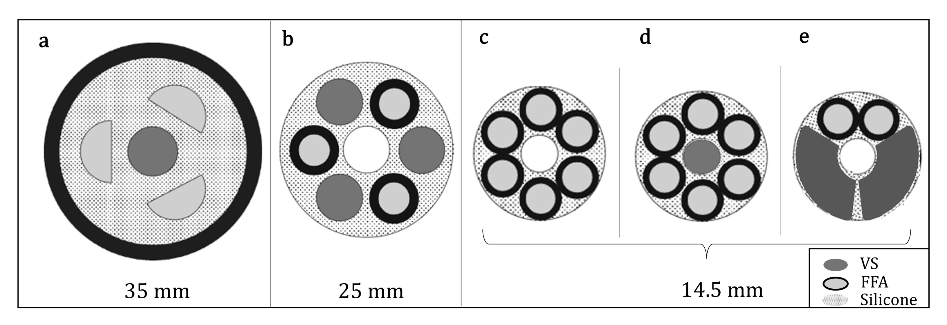
2.1. Manipulator Structure and Design Considerations

The original STIFF-FLOP module presented in [7] comprises three pairs of FFAs useful for actuation radially arranged around a central axis, while the body is made of silicone. FFAs present a thin wire in a tight helical winding. When the chamber is pressurized, the minimization of the pitch allows containing the radial expansion of the chamber [24] and therefore maximizes the longitudinal elongation. This enables omnidirectional bending and longitudinal elongation depending on the pressure applied to the chambers. Each pair of chambers generates one motion primitive (MP). Therefore, the soft manipulator has three MPs for bending motion due to the inflation of each pair of chambers and one MP which is the result of simultaneous pressurization of all the pairs at the same pressure value. In this work, the original STIFF-FLOP module is redesigned according to the following specifications:
  • The total length and the external diameter remain constant to maintain compliance with the standard laparoscopic trocars (diameter 15 mm) and have comparable results in terms of the bending angle covered by the module;
  • The module has a free central channel for the passage of tools to the tip;
  • The module preserves three MPs to guarantee flexibility and dexterity;
  • The module embeds a variable stiffness mechanism.
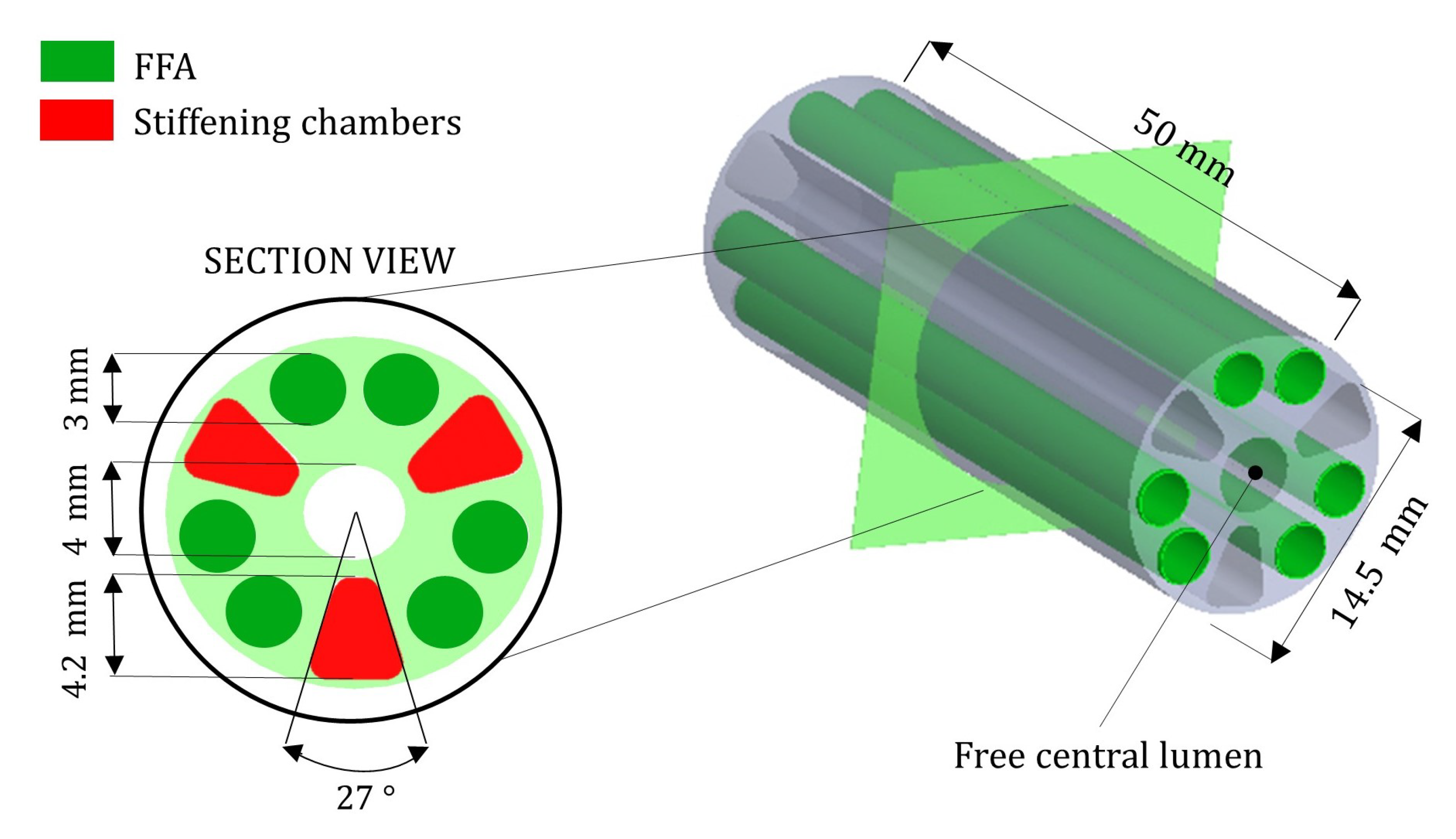
Regarding the actuation chambers, as shown in previous works related to STIFF-FLOP, the symmetry favors the repeatability of movements for a given pressure input; therefore, it may improve the controllability of the device. In addition, the arrangement in pairs has two advantages (Figure 1c–e): it allows greater stability of the manipulator during bending and maximizes the input area over which the pressure is distributed. Since the bending moment is proportional to both the applied pressure and the cross-section of the chambers, a larger area allows for a greater workspace, implying higher dexterity [25]. Moreover, the arrangement in pairs allows for allocating space for a central channel and a stiffening system despite the miniaturization constraints. For these reasons, the STIFF-FLOP design shows three pairs of cylindrical (diameter = 3 mm) FFAs with a symmetry of 120° to the central axis. The stiffening system should be able to adapt to the structure without limiting its performance in terms of flexibility and dexterity. At the same time, it must perform its main function which is to vary the compliance of the device during a voluntary interaction with biological tissues. The flexural stiffness (k) of a mechanical structure is the ability of a structure to resist bending and it is defined as the product of the elastic modulus in bending (E) and the second moment of area (I):
k = E × I
It takes into account both the intrinsic properties of the material and the geometry of the structure [26]. It depends not only on the area but also on the distribution of that area with respect to the neutral axis (where there are no longitudinal stresses or strains). If the material can be considered isotropic and the transversal cross-section of the structure is symmetric and not curved before a bend occurs, then the neutral axis passes through the geometric centroid, which falls at the center of the central channel, which is the case for the device proposed in this work. Therefore, to obtain a significant stiffness variation, the stiffening chambers should be placed far from the axis of rotation and their base area should be maximized. In a previous version of STIFF-FLOP [27], the first attempt to have eccentric trapezoidal stiffening chambers has already been presented, but in a device with a diameter > 15 mm, which is not compliant with the dimensional constraints of the application scenario.

2.2. New Design

With the aim of maintaining the functional advantages achieved with the previous versions of the STIFF-FLOP manipulator, the novelty in the design focuses on the stiffening chambers only. In particular, given the miniaturization constraints, the proposed new design of stiffening chambers is intended to maximize the bending moment considering also the limitations given by the fabrication process. Indeed, with the aim of maintaining a fabrication process based on the casting of the same material used in the previous versions of the manipulator, we found that the inner silicone layer that separates the actuation chambers from the stiffening chambers should be at least 1 mm thick to obtain a reproducible and repeatable result. For these reasons, the proposed stiffening chamber geometry is trapezoidal (11.40 mm2) with rounded corners and with the center of gravity facing outwards. Moreover, their arrangement is symmetrical at 120° to the central axis, as are the actuation chambers, to induce a homogeneous stiffening of the structure. This kind of design allows optimal integration of both actuation and stiffening in a soft surgical device with a diameter of 14.5 mm, thus it is suitable for MIS applications (i.e., it is able to pass through a standard trocar with an external diameter of 15 mm). Figure 2 shows the section view of the device comprising three pairs of FFAs, three stiffening chambers, and a free central lumen.

2.3. Variable Stiffness Mechanism

The proposed design presents three stiffening chambers for embedding the VS mechanism. As reported in Figure 2, two different VS mechanisms are proposed and implemented, namely FJ and LMPA.

2.3.1. Jamming Transition

Regarding the first one, since a precise design methodology to select the most suitable fibers is missing, they are selected through a comparative experimental analysis. In particular, the choice of fibers to be used in the system is driven by the main results that our research group has reported in previous work [12]. In particular, fibers have been investigated and tested in two different configurations: bundle-type (BT) and comb-type (CT). The first one (i.e., BT) relies on fibers that are longitudinally arranged in a bundle fixed on one side only and without a specific scheme, while the CT configuration presents fibers organized as two tooth-interlocking combs, displayed in blue and red colors as top-side and bottom-side fibers in the top-right of Figure 3. Although other combinations of materials and configurations are possible, in the present study, nylon fibers arranged in a CT configuration are adopted, according to the following criteria:
  • Shape: fibers should have a cross-section shape able to fill the inner part of the chambers as efficiently as possible.
  • Flexibility: fibers should be highly bendable, either thanks to a low Young’s modulus or their geometrical features.
  • Elasticity: the material should not undergo plastic deformation during loading and its elastic return should be taken into consideration to restore the initial state and position when the vacuum is removed.
Fibers have been confined in the stiffening chambers by using the same guidelines defined in the previous work in terms of packing factor (i.e., the volume of the fibers divided by the volume of the section). In particular, keeping the same packing factor, 12 fibers are allocated in each stiffening chamber since each fiber has a diameter of 0.9 mm.

2.3.2. LMPA

The alternative stiffening system proposed is based on an LMPA. The melting temperature is the main parameter that drives the choice of a specific LMPA and it depends on the composition of the alloy that, in turn, determines the mechanical properties of the material [28]. Given the intended biomedical application, the operating temperature range (both in solid and liquid states) should be safe for close interaction with the human body. Several alloys with a low-melting-point are commercially available. The melting point of rubidium is much closer to body temperature, but rubidium is unstable in its elemental state. The same limitation applies to cesium. Gallium is also unsuitable because it has a strong tendency to supercool below its melting point [28,29]. Melting points of Cerrolow 117 and Field’s metal are also close to body temperature and they are stable in air. Cerrolow 117 is a highly toxic alloy that would represent a safety risk to the human body. Therefore, the proposed VS mechanism is based on Field’s metal which shows low level-toxicity since it contains neither cadmium nor lead. Its physical and mechanical properties are shown in Table 1 [30]. Moreover, it has been used in several applications where materials with controllable stiffness may be integrated into soft structures [17,31]. In order to quantitatively characterize the stiffness of Field’s metal in the rigid state, its elastic modulus was measured using a tensile test according to ISO 6891-1. Three test specimens of Field’s metal were fabricated and were stretched at a rate of 500 mm/min until breaking. From the experimental results, it was possible to estimate a Young’ modulus (E) of 2.91 ± 0.13 GPa and an ultimate stress of 25 ± 2 MPa.
In the current state-of-the-art methods, different solutions to achieve melting of the LMPA have been reported. For instance, Zhao et al. [17] proposed to adopt hot and cold water flowing through channels lodged on the over-tube to achieve fast melting and solidification of LMPAs. This approach requires space for allocating the hydraulic circuit, and since the size of a device for MIS is a limiting factor, other strategies were investigated. Among them, Tonazzini et al. [16] proposed to use an external heater made of a conductive wire that wraps the LMPA. This strategy allows to embed the heating system directly in the stiffening chambers without occupying additional space; therefore, it has been adopted in this work. As reported in the bottom-right of Figure 3, the heating system is based on a conductive wire which is helically wrapped around the LMPA core (Field’s metal, HiTech Alloys, WA, USA). The material chosen for the conductive wire was tinned copper (RS PRO, Single Core, 0.21 mm), which is particularly appropriate where excellent electrical conductivity and thermal resistance are required. When a current provided by a power supply is applied to the heater, the temperature of the LMPA core increases due to the Joule effect (refer to Appendix A.1 for a more precise analytical description). When the LMPA melting temperature of 62 °C is reached, the LMPA core transitions from a solid (stiff) to liquid (soft) state. This strategy relies on an electric circuit that provides active melting, whereas the cooling is passive, so the melting speed is higher than the cooling. Cooling of the samples is primarily due to convection; thus, its speed is a function of both the final sample temperature and the surface area of the silicone encapsulation.

2.4. Fabrication

Manufacturing of the module consists of several steps based on the silicone molding procedure, very similar to the process previously introduced in [7]. All the components for the module fabrication were made using a 3D printer (ProJet MJP 3600, 3D Systems, South Carolina, US). For a better representation of the manufacturing procedure, the main phases are listed below and summarized in Figure 4.
(a)
Firstly, cotton thread was wrapped around the cylindrical mold of the fluidic chamber. The cylinder consists of three parts, one central and two sides (Figure 4a), so that the demolding steps are made easier.
(b)
Six molds were placed inside the manipulator mold together with a central core and three trapezoidal prisms (stiffening chambers). To guarantee a precise mold alignment, which is essential for avoiding any asymmetries in the module, both fluidic and stiffening chamber molds were held in place by a Plexiglas plate which is located on the top of the module. The Plexiglas component (thickness = 4 mm) was produced with a laser cutting machine (Universal Laser XLS10MWH, Universal Laser System Inc., South Carolina, USA). Then, uncured silicone (Ecoflex 0050, Smooth On Inc., Macungie, PA, USA) was poured into the mold and left to cure at room temperature. After the silicone had completely cured, all molds were removed (Figure 4b).
(c)
After obtaining the main silicone body of the manipulator, the next phase comprises the integration of the variable stiffness mechanism. For the FJ module version, a total of 36 fibers (i.e., 12 per chamber) were inserted in CT configuration in each stiffening chamber. In each module, the fibers were arranged as two tooth-interlocking combs: half were placed more than 3 mm from the bottom face of the module and the remaining amount was placed at the same length from the other side.
For the LMPA module version, the LMPA core and heater were inserted in each stiffening chamber (Figure 4c). More details on this step are discussed in Appendix A.2.
(d)
The modules were sealed on the bottom side using a dedicated cup mold filled with harder silicone (Smooth Sil 950, Smooth On Inc., Macungie, PA, USA). At this stage, the pipes for the fluidic actuation (i.e., three for both modules) were incorporated into the soft structure. For the FJ module version, one pipe for the vacuum was also inserted (Figure 4d).
(e)
The last step comprises the top sealing of the modules using the same procedure described above. Actuation chambers were connected in pairs through a silicone pipe located internally (Figure 4e). Figure 4f shows the final result.

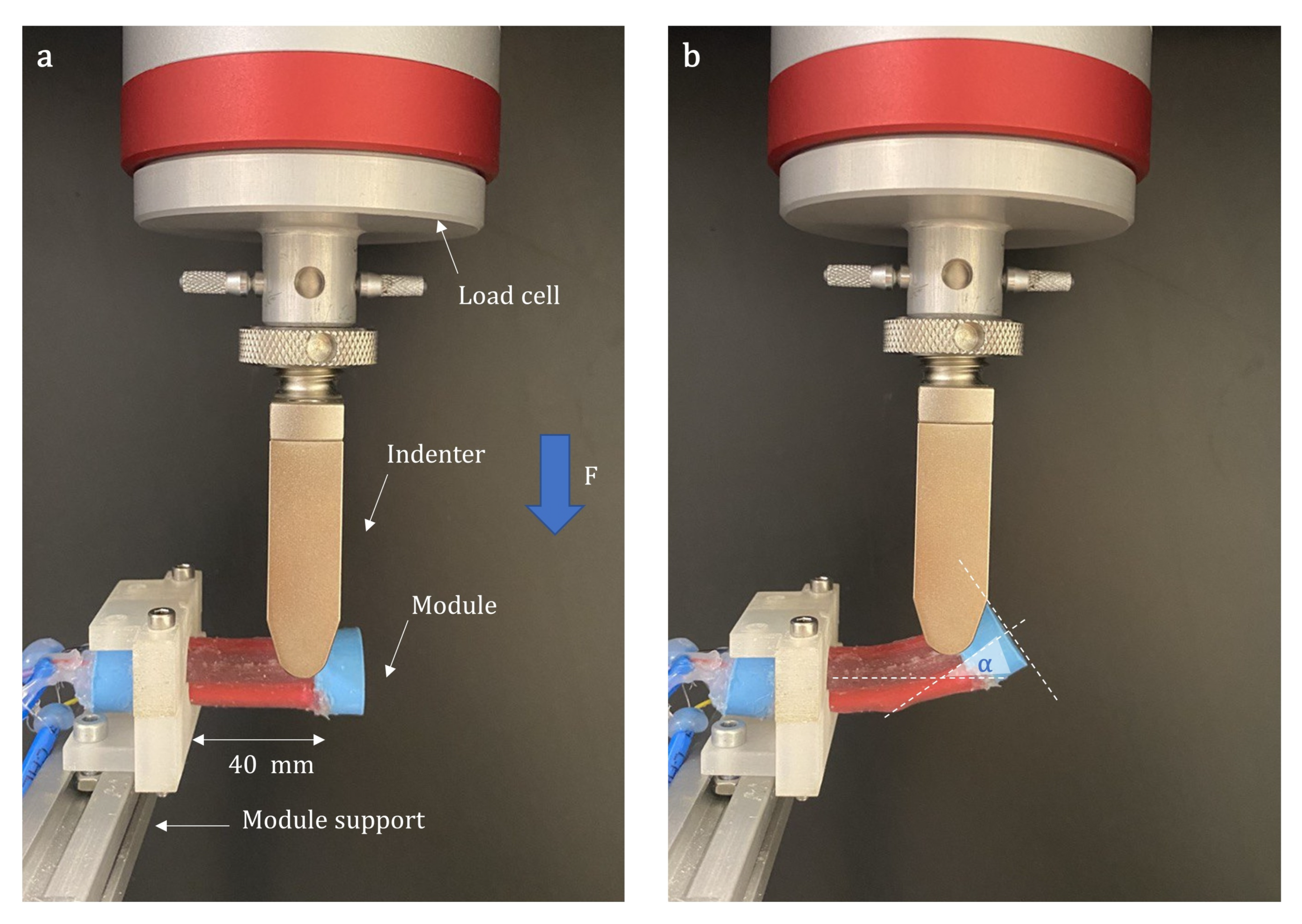
2.5. Experimental Setup and Protocols

In order to investigate the performance of the variable stiffness mechanism and compare the two approaches, the modules underwent a characterization protocol in line with the one adopted in the original study [11]. Four different characteristics were experimentally evaluated: (i) the variable stiffness at rest position; (ii) the variable stiffness in a bent configuration; (iii) the bending angle; and (iv) the shape locking capability. The experimental setup counts on parts that are used to drive the FFAs and the VS mechanism. For the fluidic actuation, the pressure inside each pair of chambers was controlled by a proportional pressure regulator (K8P-0-D522-0, Camozzi Group) directly connected to an air compressor (Leonardo 101, FIAC S.p.A.). For driving the FJ module, a simple On/Off vacuum control was selected and implemented by using a vacuum pump (Oil Lubricated Rotary Vane Pumps MM56p2, D.V.P Vacuum Technology s.r.l., Carpanelli S.p.A.). The vacuum working state, measured by an absolute pressure sensor (SWCN-V01-P3-2, Camozzi Group), corresponds to a 0.1 bar pressure level, whereas the ambient pressure was set as equal to atmospheric pressure. Regarding the LMPA module, a power supply (P1535, 30 V, 12 A, 640 W, PeakTec) was used to induce the melting of the LMPA. For each test, three samples were taken into consideration. Samples were tested in terms of force vs. displacement using a universal testing machine (INSTRON 5965, Norwood, MA, USA) equipped with a 1 kN load cell. Then, the post-processing of experimental data was carried out in MATLAB (Mathworks, 2021) to evaluate the mean and standard deviation. The specific tests are detailed in the subsections reported below.

2.5.1. Variable Stiffness at Rest Position

These tests aim to quantify the contribution of the variable stiffness mechanism to the overall stiffness of the modules at rest position. Bending tests needed an ad hoc metallic housing to host the device, indeed, an L-shaped frame was placed in the testing machine so that the lower end could be fixed and the upper one was free (cantilever beam configuration), as shown in Figure 5a. In order to apply a point load, an indenter was used. The module tip was deflected vertically for a distance of 15 mm at a speed of 15 mm/min. The point of contact at the interface between the Ecoflex 00–50 and the Smooth Sil 950 represents the origin of the reference system integral with the module and allows to consider only the central area in the calculation of the bending stiffness. Six experimental trials were performed for each module: three in the soft state and three in the stiff state.

2.5.2. Variable Stiffness in Bent Configuration
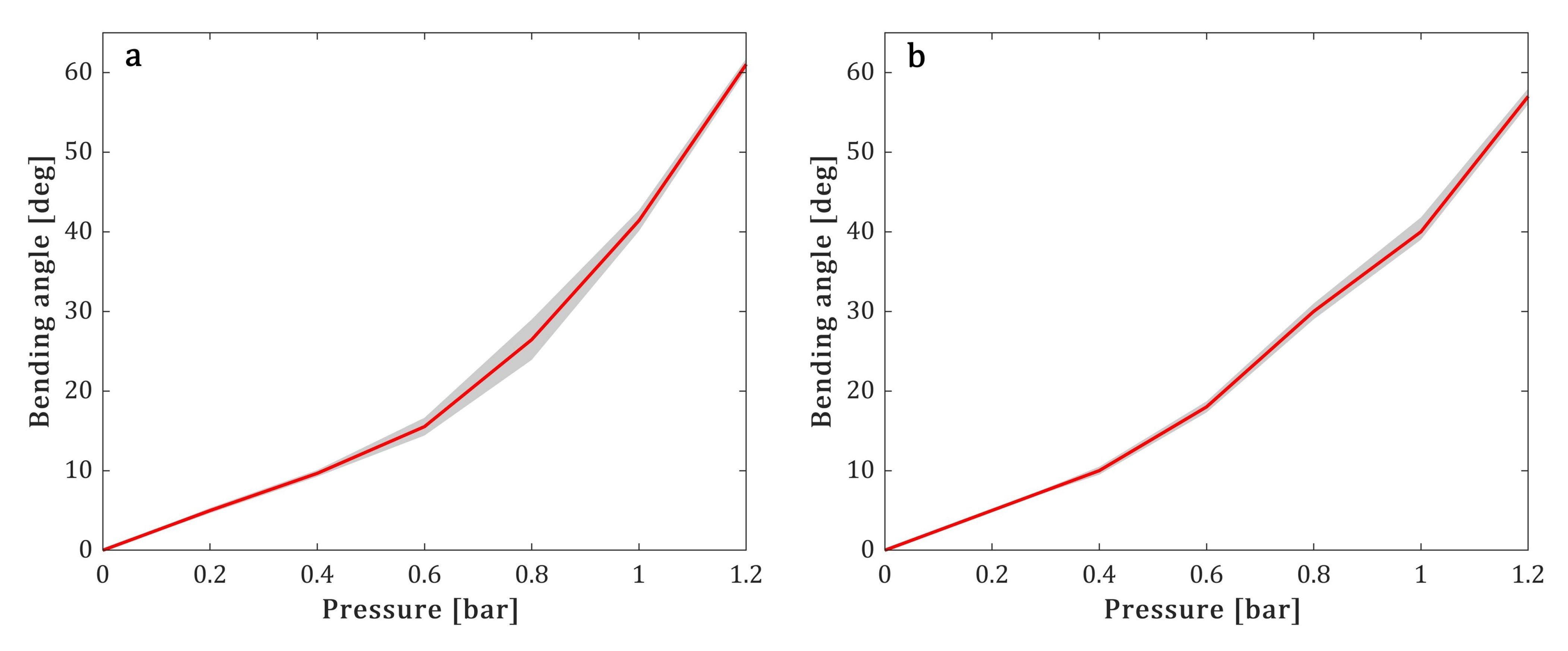
The same setup was used to evaluate the variable stiffness in the bent configuration as shown in Figure 5b. The stiffness variation recorded in this configuration can be related to one of the previous tests in order to evaluate how the deformed state of the module affects the stiffening capability of the variable stiffness mechanism. In this case, before applying the vertical load, one pair of chambers along the relative MP of each module in the soft state is activated using a pressure of 1 bar. Then, three trials were carried out in the soft state, and three were carried out in the stiff state, for each module. The application point was the same as the test at rest position. The maximum forces for all tests were recorded and compared.

2.5.3. Workspace

This test aims to evaluate how much the presence of the VS mechanism affects the dexterity of the manipulator. Thanks to the symmetry of the design of the module, to have an indirect measure of the module’s workspace, the bending angle was measured in relation to the applied pressure on a single plane. The input air pressure ranged from 0 to 1.2 bar with an increment of 0.2 bar and inflated a pair of chambers for each module. The workspace was evaluated by the capability of each chamber to bend the module on a single plane. The bending angle, α , is derived as the angle between the vectors normal to the module base and the tip surfaces on the bending plane, as shown in Figure 5b. A total of three trials were conducted for each module in the soft state, activating only one pair of chambers and recording the process through a high-resolution digital camera (Canon EOS 6D). Then, image processing was carried out using ImageJ software.

2.5.4. Shape Locking

The ability of the module to maintain a certain position once the pressure in the fluidic chamber has been removed is called “shape locking”. The procedure for carrying out the test includes the following steps, using the same setup described for the workspace evaluation.
  • The module in the soft state is bent, supplying a pressure of 1.2 bar to a pair of chambers;
  • The angle α is recorded ( α 1 );
  • The transition from the soft to the stiff condition is triggered;
  • The pressure is removed from the fluidic chambers;
  • The angle α is recorded again ( α 2 ).
The tests were repeated three times.

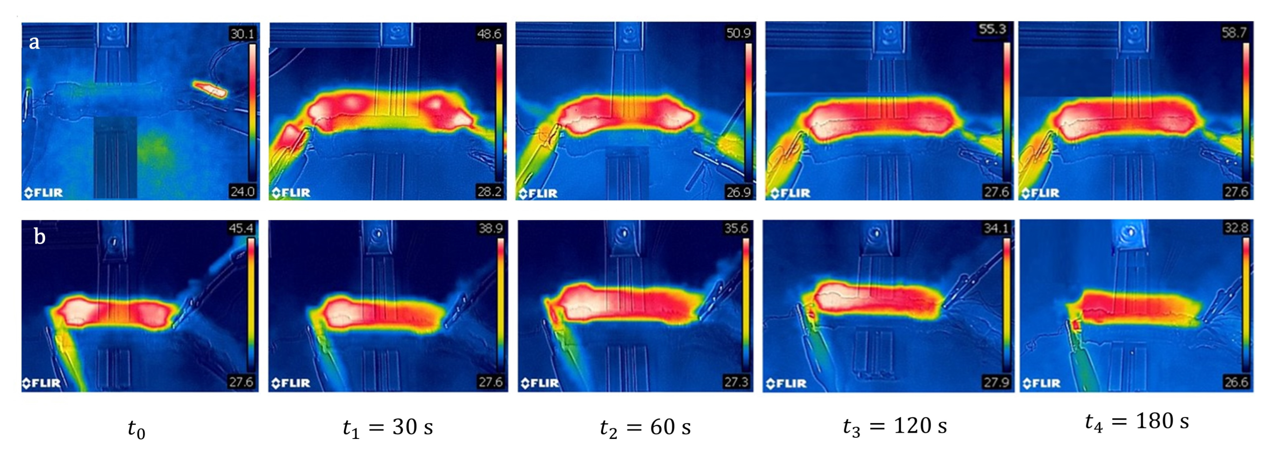
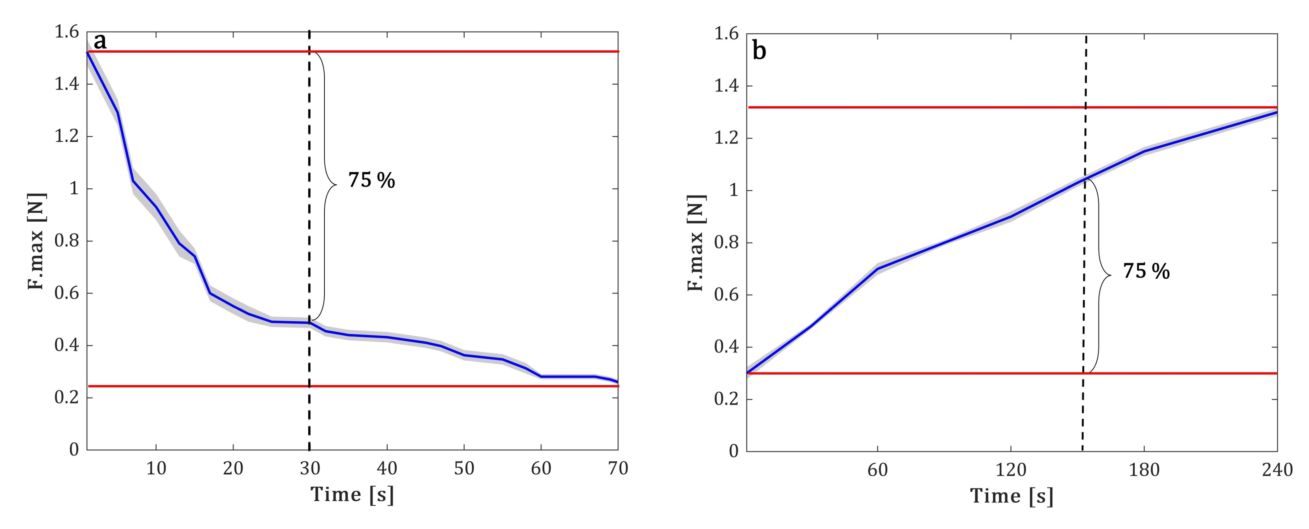
2.5.5. Transition Time Evaluation

The transition time for the FJ modules is in the order of a few seconds, and since this is much faster than LMPAs, it was not experimentally measured. Data from the literature were considered in place of additional tests and mentioned in subsequent sections to make a comparison between the two module versions.
The protocol used to estimate the transition time of the LMPA modules is reported in this section. By heating the LMPA to a temperature above 62 °C, the state of the material changes from solid to liquid. Thus, the stiffness of the material changes dramatically. To test the melting time of the LMPA, the mechanical response of the device was analyzed in a cyclic test. The protocol started with the module in a stiff condition, then the heating system was switched on (see Appendix A.1), and the same deflection test introduced in Section 2.5.1 was performed. The module tip was anchored to the indenter to avoid the distorting effect of the plastic deformations. Preliminary tests allowed defining a safe testing range in which the LMPA cores did not experience failure; the module vertical deflection was set to 5 mm with a speed of 200 mm/min for N = 50 cycles. In this small displacement range, the device is expected to support higher forces in the first cycles, then lower forces in the following cycles, as the LMPA cores start the transition phase. Therefore, the assessment of the trend of the maximal force for each cycle can be considered informative of the melting time. To evaluate the cooling time, a similar test was performed, starting with the soft configuration and finishing with the stiff one. The parameters of the cyclic test remained unchanged except for the number of cycles, which was greater (200) in light of the slower speed of cooling when compared to melting. Moreover, to qualitatively assess the thermal behavior of the device, a thermal camera (FLIR C5, −20, +200 °C) was used. Regarding the melting time, for a given set of power supply parameters, the analysis aimed to investigate the distribution of temperature of the device over time starting from the stiff state. For the cooling time, the test was similar but started from the soft state.

3. Results and Discussion

In this section, the results obtained for each experimental test are reported and discussed. The analysis is based on the comparison between the performances of the two proposed versions of the module with respect to the original STIFF-FLOP module [7] and the two designs proposed in [11].

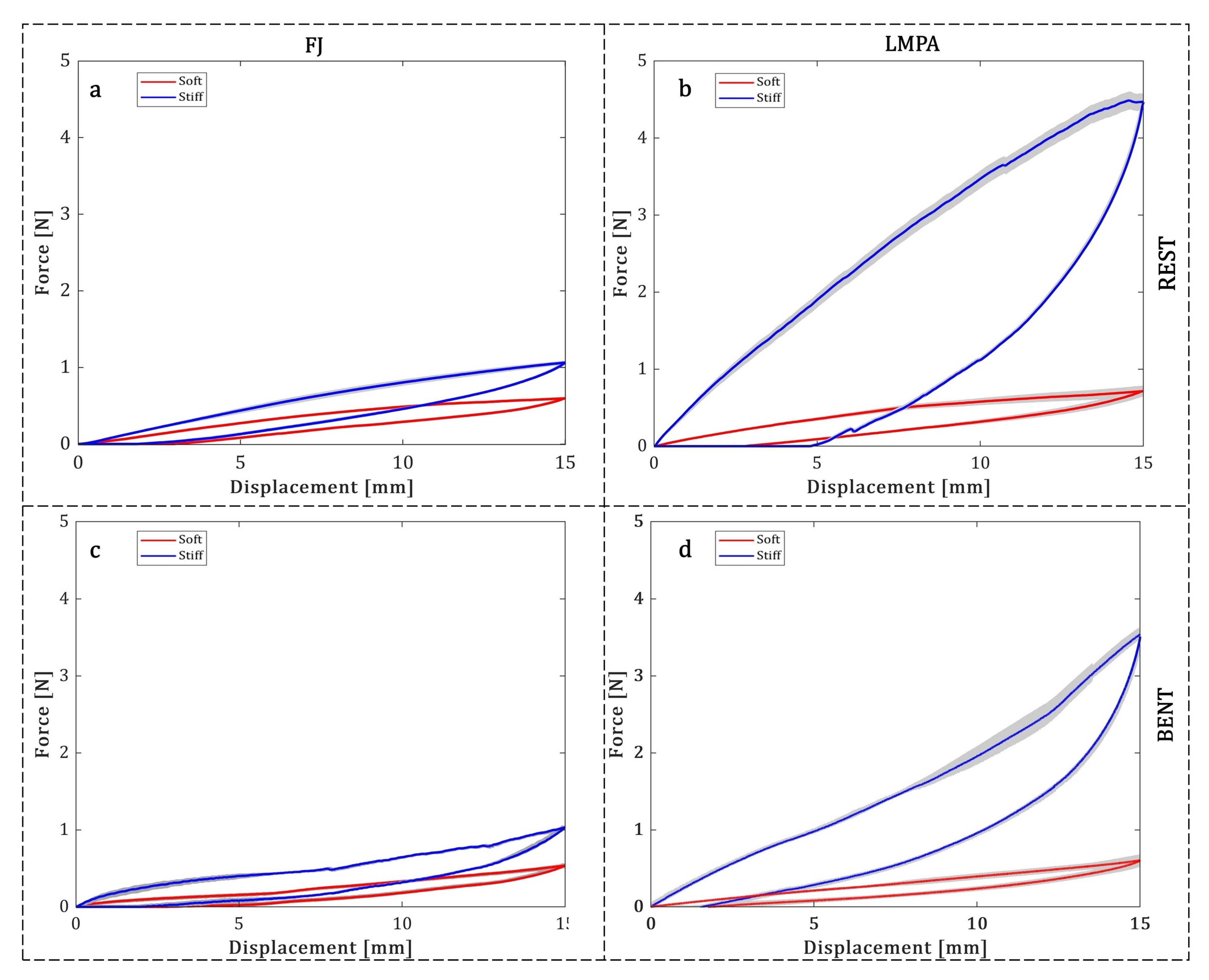
3.1. Variable Stiffness in the Rest Position

Figure 6a–d reports the force–displacement curves for each module and Table 2 summarizes the results concerning the maximum stiffness variation that can be achieved. The first observation regards the maximum force sustained in the soft state. It is remarkable that despite the VS mechanism being completely different, the difference between the soft state behavior of the two versions is negligible. The second last column of Table 2 reports the ratio between the maximum force measured in the soft state and the stiff state condition. This is the most appropriate parameter to assess the module performance and to provide a direct comparison of the stiffening capability in the entire tested range.
The LMPA module can sustain a maximum force of about 4.51 N with respect to 1.06 N for the FJ module. The last column of Table 2 also reports the ratio between the elastic constants in soft and rigid states, derived from the linearization of the first interval of the curve (0–1.5mm). This parameter allows to assess the module performances in a small range of displacement. These results slightly differ from the force variation data for both modules. Indeed, in the first interval of the curve, silicone compression may occur, reducing the effectiveness of the VS mechanism, which results in lower values in the stiffness variation data. However, the stiffness variation is still remarkable even in this condition. Overall, the stiffening performance follows a trend that is coherent with expectations. Indeed, the LMPA module shows a wider stiffness variation with higher load-bearing capability than the FJ module. In the stiff state, depending on the load-sustaining limit, a module with a VS mechanism may be exploited in MIS. For instance, a common task in MIS for abdominal surgery is the retraction of soft organs. The required retraction force for some soft organs ranges from 1 N for the stomach to 5 N for the intestines [32].
In addition to these quantitative data, it is worth reporting that during these tests, once the imposed displacement was completely removed, the modules in the soft state completely recovered their initial position without showing significant residual deformation.

3.2. Variable Stiffness in the Bent Condition

In the soft state, the values of the maximum force for both modules are comparable to the ones at the rest position, as reported in Table 3. The stiffening variation and maximum force in the rigid state are slightly lower than the ones for the bending test at the rest position. However, the dominant role played by the LMPA and FJ is also confirmed in the bent configuration, since the stiffness variation and the maximum force in the rigid state are still remarkable. These data, together with those reported in Section 3.1, support the concept of using such kind of modules to provide stability against external disturbances.

3.3. Workspace

The results related to the workspace are limited to the evaluation of the performance of the manipulator on a single plane of bending. In particular, Figure 7 shows the bending angles corresponding to pressure increases for both modules. The obtained bending angles for both technologies have a very similar trend and reach values up to about 60°. This underlines that both VS mechanisms (when in the soft state) introduce the same amount of resisting force when subject to bending.

3.4. Shape-Locking

The ability to maintain a deformed shape has been evaluated as the residual angle that the manipulator can maintain in the stiff state once the fluidic actuation is turned off. The experimental results show that the LMPA module presents a higher residual angle with respect to the FJ module, as reported in Table 4; in particular, the alloy inside the device tends to counteract the elastic return more effectively due to the silicone (recovery of the initial shape after the application of the pressure input). Remarkably, this deformed state is preserved in the LMPA module without power consumption, and also in the FJ module as long as the valve prevents any leakages. Moreover, it may be highlighted that to maintain the soft state in the LMPA module, power consumption is needed, whereas for the FJ module, it is required ideally only in the transition from soft to stiff.

3.5. Transition Time Evaluation

In the LMPA module, the transition is thermally activated, meaning that it has a low energy transduction efficiency and the transition time is limited by thermal inertia. Figure 8a reports the trend of averaged F . m a x over three samples during the melting process. In the first 9 s, the F . m a x decreases by 50% of the entire range, and in about 30 s by 75%. From 30 s to 60 s, there is an additional decrease of only about 20% (maximum variability ± 11% at 20 s). Therefore, the melting process could be considered almost complete in 30 s and fully complete in 60 s. Indeed, the device consists of 90% silicone, which is a material with excellent heat insulation properties, and therefore the heat loss due to the environment during melting might be limited. This means that the silicone matrix allows to speed up the melting process, maintaining a much lower temperature at the level of the external surface. Regarding the cooling speed, a similar experimental procedure was used and the results are reported in Figure 8b. In this case, the trend of maximum force is increasing over time since the load-bearing capability increases as the transition from the soft to the rigid state occurs. Since cooling is a passive process, it has slower dynamics than melting; thus, the maximal force supported by the device for each cycle of the test was evaluated over an extended time range of 240 s. In the first 60 s, the maximum force, F . m a x , increases by 50% of the entire range, then in 150 s by 75% (maximum variability ± 8% at t = 60 s). Despite the significantly long timing, the stiffening capability of the device changes remarkably in 60 s. As such, the device may be used as part of a safe surgical device; it may be maneuvered to reach the surgical site while it is soft, and (when the target is reached) it may be stiffened to perform the surgical tasks. The slow response time of the LMPA represents an obvious intrinsic limitation of this technology for applications that require multiple transitions between soft and stiff states (and vice versa). However, given the high load-bearing capability, also highlighted in Section 3.1 and Section 3.2, the device may be especially useful for static tasks where the rigid state is exploited and the transition from the soft to the rigid state is required just once. Under these circumstances, it can be acceptable to have a significantly slower cooling phase than melting phase.
Since the experimental results show that the melting process is very advanced after about 30 s, a specific evaluation of the temperature of the device at that time may be informative of the actual thermal status of the device in the soft state. Starting from T 0 = 25 °C (Figure 9a), the maximum temperature is 48 °C at t 1 = 30 s (Figure 9b).
Considering a potential biomedical application, at this temperature, a long time of direct contact with the patient’s body would injure biological tissues. This implies the need for additional elements or strategies to keep the surface temperature of the device as low as possible. For instance, to improve the safety of the device, an additional heat insulation layer may be considered. This layer would not significantly affect the mechanical performance of the device and might still be compliant with dimensional constraints. In addition, due to the heat preservation property of the heat insulation layer, as a beneficial effect, the transition time between the rigid and flexible state would be shortened. However, the cooling process would be slowed down. Regardless of whatever clever solution is adopted, the thermal behavior that is intrinsically in LMPA technology represents a high limitation in MIS, despite its remarkable load-bearing capability. Nevertheless, this could still be compliant with other application scenarios where direct contact with body tissue does not occur. The thermal behavior of the device in the transition from the stiff to the soft state is shown in Figure 9c,d. Starting from a maximum temperature of about 45 °C, the device cools down slowly and reaches a value of 36.5 °C in about 120 s, while in about t 4 = 180 s, the cooling process leads to an average temperature of 32.5 °C. Refer to Figure A2 for a complete view of the qualitative thermal evaluation of the device. In the FJ module, the transition between the stiff and the soft state depends on vacuum pump inflow and outflow, and therefore it can be considered to be on the order of a few seconds [33].

3.6. Performance Improvement in the STIFF-FLOP Manipulator

The STIFF-FLOP manipulator was originally conceived to represent a valid alternative to MIS tools, with additional advantages such as higher dexterity and intrinsic safety. The objective was largely achieved, but with limitations in some functionalities. The most important limitation is the exertion of limited forces because of the softness of its body together with the absence of a VS mechanism. Subsequently, several efforts have been exerted to potentially integrate a VS mechanism without affecting the other optimized performances. Nevertheless, even in the soft state, the integration of a VS mechanism introduces a slight additional resistance to bending, as shown in Table 2, namely 0.59 N for the FJ module and 0.63 N for the LMPA module, with respect to 0.36 N of the original STIFF-FLOP module [7]. This is not the case for the two modules embedding FJ proposed in [11], which show a maximum force in the soft state of about 0.33 and 0.43 N, thus being comparable to the original module. Observing the performances in terms of workspace for both the FJ and LMPA modules and comparing the results with the STIFF-FLOP original module (i.e., a bending angle of 132.2 ° at 1.2 bar [34]), the integration of the fibers and the LMPA considerably decreases the module workspace, in line with the results of Brancadoro et al. [11]. This effect was predictable and reasonable; the absence of a VS mechanism allows high dexterity, but low forces. Indeed, on the other hand, the proposed design either with FJ or LMPA outperforms, in terms of the achievable stiffness, both the original module (which does not have any VS system) and the two previously proposed designs [11]. In addition, the proposed design preserves all four MPs of the STIFF-FLOP module with a free operating channel.
FJ is currently limited by the use of circular fibers (that leads to a limited contact surface between fibers), but it offers low transition times with good stiffening capability and dexterity with no heat involved in the transition phases. LMPAs need heat and long transition times that may represent a limitation; moreover, its low yield stress may represent a further issue, especially in terms of the potential risk of breakage. However, LMPAs offer remarkable stiffness variation with a fairly good degree of flexibility, and they show the property of self-healing according to a heating (melting)–cooling (solidifying) process. In Figure 10, a summary of these attempts has been reported, highlighting the advantages and disadvantages of the proposed approaches.

4. Conclusions and Future Perspectives

Starting from the preliminary results obtained by Brancadoro et al. [11], here we presented a novel design of the STIFF-FLOP manipulator that integrates a variable stiffness mechanism. The device is miniaturized, provided with a free working channel of 4 mm in diameter, and has an external diameter of ≤15 mm; thus, it is still compatible with standard MIS instrumentation for abdominal procedures (trocar port access). The integration of the VS mechanism enables the possibility to vary its compliance from a flexible to a rigid state and vice versa. The results of all the experimental tests show that the newly redesigned module embedding the proposed VS mechanisms outperforms the latest versions presented by the same research group in terms of stiffness variation, dexterity, and flexibility in both cases (Figure 10).
However, neither the LMPA nor the FJ approach can be considered ideal. LMPAs allow for achieving high stiffness and significant load-bearing capability in the rigid state, but at the cost of a long transition time and possible thermal implications. FJ is a fast, simple, and versatile mechanism, but it allows for achieving less remarkable stiffness variation. Moreover, in both cases, the performances are affected by a fabrication process that still requires a series of manual steps.
Nevertheless, the two proposed VS mechanisms demonstrate a concrete potential to make the manipulator a usable tool in the medical field. The choice between LMPAs and FJ should be led by the specific limitations implied in the target application, where it is possible to leverage the respective advantages and neglect or manage their drawbacks. The stiffness can be adjusted to ensure flexibility and dexterity during the navigation phase and to obtain rigidity to stabilize the manipulator and exert and propagate higher forces to perform surgical procedures once the surgical target is reached. This also represents the technological base to improve the effectiveness of two-module surgical manipulators [7]. A proximal module with a VS mechanism would be able to increase the stability of the manipulator, while the distal module could maintain dexterity and would exert higher forces when driven to interact with tissues.
Finally, it is important to underline that, in both approaches, the rigid state is maintained without power consumption, which represents an efficient solution for static tasks such as soft organ retraction.
The proposed design, together with the selected technologies, demonstrated suitable features for enabling stiffness variation in soft-bodied arms, and in our specific case, it facilitates the shift from an endoscopic tool (mainly devoted to inspection and whose main requirements are dexterity, maneuverability, and safe interaction), to a surgical tool (with higher stiffness to interact effectively with the surgical site) that may represent an ultimate step forward to meet clinical needs.

Author Contributions

Conceptualization, N.P. and L.A.; Methodology, N.P., L.A., S.A. and M.C.; Data curation, N.P.; Writing—original draft, N.P. and L.A.; Writing—review & editing, M.C.; Supervision, Matteo Cianchetti; Project administration, M.C. All authors have read and agreed to the published version of the manuscript.

Funding

This research received no external funding.

Conflicts of Interest

The authors declare no conflict of interest.

Appendix A

Appendix A.1. Selection of the Heating System

The first possible approach to melt the alloy is the simplest one. Indeed, since LMPAs are metals, direct Joule heating given by an LMPA itself may be considered. For simplicity, the following considerations rely on two main assumptions: firstly, the estimation assumes a uniform distribution of temperature in the module, viewed as a composite (an LMPA and silicone) and no heat loss with the environment; secondly, since the temperature range in the transition of the LMPA (25–62 °C) is limited, changes in resistivity due to the increase in temperature are negligible ( < < 10 8 Ωm); therefore, resistance could be considered constant. Considering room temperature conditions ( T e n v = 25 °C), the total heat to melt the alloy starting from T e n v includes the contribution to increase the temperature of the alloy to the melting point and the latent heat to allow the phase transformation. According to the first law of thermodynamics, the energy needed to melt the metal for a given structure can be estimated as:
P t = m c Δ T + m C
where P is the power of the heater, t is the time, m is the mass of the metal, c is the specific heat, Δ T is the temperature difference between the T e n v and the melting point, and C is the latent heat of the metal. If the metal is melted by direct joule heating, P can be written as:
P = i R 2
where R is the resistance of Field’s metal (resistivity = 52 × 10 6 Ωm at T e n v ) and i is the current. According to Equations (A1) and (A2), the melting speed is not only related to the current but also to the structure of the metal. Considering the upper limit for the complete melting of the LMPA cores, t i d e a l = 30 s and so P = 7 W. Since the electrical resistance given by the LMPA core is relatively low (R ≈ 2 × 10 3 Ω), the value of the required power is very high and incompatible with a possible biomedical application. Therefore, other approaches may be investigated as the Joule effect given by a conductive wire, in particular copper (resistivity = 1.68 × 10 8 Ωm at T e n v ). In the proposed LMPA module, the heater consists of a wire that wraps each LMPA core. Different diameters (0.1–0.3 mm) of commercial copper conductive wires are taken into consideration. For the desired melting time t i d e a l , a 0.1 mm wire allows to minimize the value of required current, but the winding process is manual and thus difficult and not very repeatable, while the 0.3 mm wire is easily wrapped but the required current is significantly high ( i 0.3 mm ≈ 5 i 0.1 mm ). Therefore, the choice of the heating system is based on a trade-off between the controllability of the fabrication process and the required current for melting ( i 0.2 mm ≈ 2.5 i 0.1 mm ); consequently, a 0.2 mm wire ( R w i r e ≈ 0.8 Ω) was chosen in the final prototype, the melting time was set to 30 s and a power supply capable of providing i ≈ 9 A was required (the electrical circuit is shown in Figure A1a).
Figure A1. (a) Schematic representation of the heating system. (b) Substeps of step of the fabrication for the LMPA module to produce the LMPA+heater to embed in the stiffening chamber.
Actuators 12 00096 g0a1

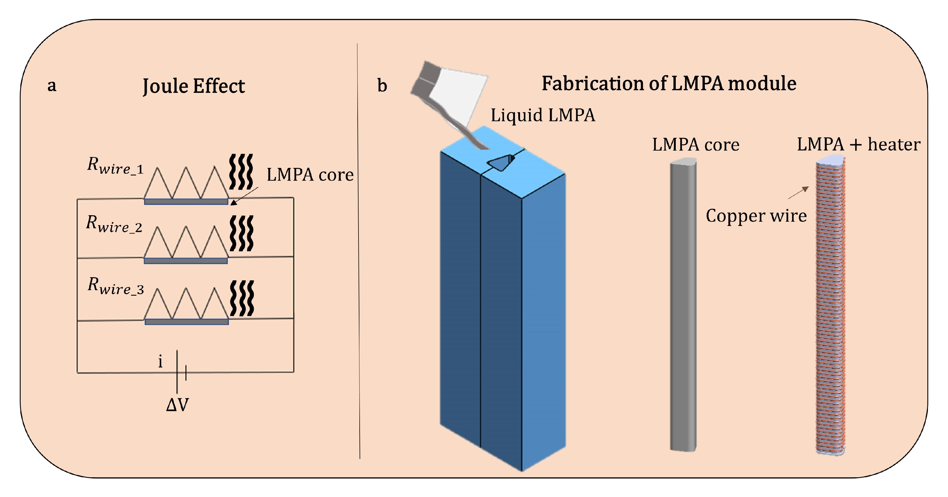
Appendix A.2. Manufacturing of the LMPA Core

As reported in Section 2.4, after obtaining the central body of the module, the next phase comprises the integration of the LMPA and the heater in the stiffening chambers, shown in Figure A1b. The proposed approach requires pouring the liquid alloy into a mold that replicates the shape of the stiffening chamber. The mold was composed of plexiglass walls (2 mm thickness) and silicone (MoldStar 00–30, Smooth On Inc., Macungie, PA, USA). Then, the conductive wire was wrapped around the obtained LMPA core, and the LMPA core containing the heater was inserted into the stiffening chamber.

Appendix A.3. Thermal Analysis

The thermal behavior of the module was assessed for 180 s during the transition phases. For the melting process, the power supply was set to i = 9 A for the total time of the test. Since the melting process was almost complete after 30 s, as reported in Section 3.5, the cooling process was analyzed after melting for 30 s once the power supply was switched off. From the stiff to the soft state, the temperature of the device rapidly increased in the first 30 s from 25 °C to 48.6 °C, and then it slowly rose to 58.7 °C after 180 s. From the soft to the stiff state, the temperature of the device decreased gradually from 45.4 °C to 35.6 °C in 60 s and to 32.8 °C in 180 s.
Figure A2. Qualitative thermal analysis of the LMPA module during the transition from (a) the stiff to the soft state (b) the soft to the stiff state.
Actuators 12 00096 g0a2

References

  1. Laschi, C.; Mazzolai, B.; Cianchetti, M. Soft robotics: Technologies and systems pushing the boundaries of robot abilities. Sci. Robot. 2016, 1, 1–11. [Google Scholar] [CrossRef] [PubMed] [Green Version]
  2. Rutland, B. Soft touch. Artforum Int. 2014, 53, 236–243. [Google Scholar]
  3. Cianchetti, M.; Laschi, C.; Menciassi, A.; Dario, P. Biomedical applications of soft robotics. Nat. Rev. Mater. 2018, 3, 143–153. [Google Scholar] [CrossRef]
  4. Runciman, M.; Darzi, A.; Mylonas, G.P. Soft Robotics in Minimally Invasive Surgery. Soft Robot. 2019, 6, 423–443. [Google Scholar] [CrossRef] [Green Version]
  5. Vitiello, V.; Lee, S.L.; Cundy, T.P.; Yang, G.Z. Emerging robotic platforms for minimally invasive surgery. IEEE Rev. Biomed. Eng. 2013, 6, 111–126. [Google Scholar] [CrossRef]
  6. Kim, J.; De Mathelin, M.; Ikuta, K.; Kwon, D.S. Advancement of Flexible Robot Technologies for Endoluminal Surgeries. Proc. IEEE 2022, 110, 909–931. [Google Scholar] [CrossRef]
  7. Abidi, H.; Gerboni, G.; Brancadoro, M.; Fras, J.; Diodato, A.; Cianchetti, M.; Wurdemann, H.; Althoefer, K.; Menciassi, A. Highly dexterous 2-module soft robot for intra-organ navigation in minimally invasive surgery. Int. J. Med. Robot. Comput. Assist. Surg. 2018, 14, 1–9. [Google Scholar] [CrossRef]
  8. Kwok, K.W.; Wurdemann, H.; Arezzo, A.; Menciassi, A.; Althoefer, K. Soft Robot-Assisted Minimally Invasive Surgery and Interventions: Advances and Outlook. Proc. IEEE 2022, 110, 871–892. [Google Scholar] [CrossRef]
  9. Arezzo, A.; Mintz, Y.; Allaix, M.E.; Arolfo, S.; Bonino, M.; Gerboni, G.; Brancadoro, M.; Cianchetti, M.; Menciassi, A.; Wurdemann, H.; et al. Total mesorectal excision using a soft and flexible robotic arm: A feasibility study in cadaver models. Surg. Endosc. 2017, 31, 264–273. [Google Scholar] [CrossRef] [Green Version]
  10. Shiva, A.; Stilli, A.; Noh, Y.; Faragasso, A.; Falco, I.D.; Gerboni, G.; Cianchetti, M.; Menciassi, A.; Althoefer, K.; Wurdemann, H.A. Tendon-Based Stiffening for a Pneumatically Actuated Soft Manipulator. IEEE Robot. Autom. Lett. 2016, 1, 632–637. [Google Scholar] [CrossRef] [Green Version]
  11. Brancadoro, M.; Manti, M.; Grani, F.; Tognarelli, S.; Menciassi, A.; Cianchetti, M. Toward a variable stiffness surgical manipulator based on fiber jamming transition. Front. Robot. AI 2019, 6, 1–12. [Google Scholar] [CrossRef] [Green Version]
  12. Brancadoro, M.; Manti, M.; Tognarelli, S.; Cianchetti, M. Fiber Jamming Transition as a Stiffening Mechanism for Soft Robotics. Soft Robot. 2020, 7, 663–674. [Google Scholar] [CrossRef]
  13. Manti, M.; Cacucciolo, V.; Cianchetti, M. Stiffening in soft robotics: A review of the state of the art. IEEE Robot. Autom. Mag. 2016, 23, 93–106. [Google Scholar] [CrossRef]
  14. Zhang, Y.; Lu, M. A review of recent advancements in soft and flexible robots for medical applications. Int. J. Med. Robot. Comput. Assist. Surg. 2020, 16, e2096. [Google Scholar] [CrossRef]
  15. Wang, X.; Guo, R.; Liu, J. Liquid Metal Based Soft Robotics: Materials, Designs, and Applications. Adv. Mater. Technol. 2019, 4, 1–15. [Google Scholar] [CrossRef] [Green Version]
  16. Tonazzini, A.; Mintchev, S.; Schubert, B.; Mazzolai, B.; Shintake, J.; Floreano, D. Variable Stiffness Fiber with Self-Healing Capability. Adv. Mater. 2016, 28, 10142–10148. [Google Scholar] [CrossRef]
  17. Ruzhen, Z.; Yao Yao, Y.L. Development of a variable stiffness over tube based on low-melting-point-alloy for endoscopic surgery. J. Med. Devices Trans. Asme 2016, 10, 1–8. [Google Scholar] [CrossRef]
  18. Wang, H.; Chen, Z.; Zuo, S. Flexible Manipulator with Low-Melting-Point Alloy Actuation and Variable Stiffness. Soft Robot. 2021, 9, 577–590. [Google Scholar] [CrossRef]
  19. Fitzgerald, S.G.; Delaney, G.W.; Howard, D. A review of jamming actuation in soft robotics. Actuators 2020, 9, 104. [Google Scholar] [CrossRef]
  20. Liu, J.; Wang, Y.; Zhao, D.; Zhang, C.; Chen, H.; Li, D. Design and fabrication of an IPMC-embedded tube for minimally invasive surgery applications. Electroact. Polym. Actuators Devices 2014, 9056, 90563K. [Google Scholar] [CrossRef]
  21. Kim, Y.J.; Cheng, S.; Kim, S.; Iagnemma, K. A novel layer jamming mechanism with tunable stiffness capability for minimally invasive surgery. IEEE Trans. Robot. 2013, 29, 1031–1042. [Google Scholar] [CrossRef]
  22. Narang, Y.S.; Vlassak, J.J.; Howe, R.D. Mechanically Versatile Soft Machines through Laminar Jamming. Adv. Funct. Mater. 2018, 28, 1707136. [Google Scholar] [CrossRef] [Green Version]
  23. Jadhav, S.; Majit, M.R.A.; Shih, B.; Schulze, J.P.; Tolley, M.T. Variable Stiffness Devices Using Fiber Jamming for Application in Soft Robotics and Wearable Haptics. Soft Robot. 2022, 9, 173–186. [Google Scholar] [CrossRef] [PubMed]
  24. Ranzani, T.; Cianchetti, M.; Gerboni, G.; Falco, I.D.; Menciassi, A. A Soft Modular Manipulator for Minimally Invasive Surgery: Design and Characterization of a Single Module. IEEE Trans. Robot. 2016, 32, 187–200. [Google Scholar] [CrossRef]
  25. Fras, J.; Czarnowski, J.; Macias, M.; Glowka, J.; Cianchetti, M.; Menciassi, A. New STIFF-FLOP module construction idea for improved actuation and sensing. In Proceedings of the 2015 IEEE International Conference on Robotics and Automation (ICRA), Seattle, WA, USA, 26–30 May 2015; pp. 2901–2906. [Google Scholar] [CrossRef]
  26. Gandhi, F.; Kang, S.G. Beams with controllable flexural stiffness. Smart Mater. Struct. 2007, 16, 1179. [Google Scholar] [CrossRef]
  27. Fras, J.; Macias, M.; Czarnowski, J.; Brancadoro, M.; Menciassi, A.; Gl-owka, J. 3 Soft Manipulator Actuation Module—With Reinforced Chambers. In Soft and Stiffness-Controllable Robotics Solutions for Minimally Invasive Surgery: The STIFF-FLOP Approach; River Publishers: Boca Raton, FL, USA, 2018. [Google Scholar]
  28. Wang, F.; Xing, Z.; Wang, X.; Zhao, J. A method to fabricate complex structure for variable stiffness manipulators based on low-melting-point alloy. In Proceedings of the RoboSoft 2019 IEEE International Conference on Soft Robotics, Seoul, Republic of Korea, 14–18 April 2019; pp. 491–495. [Google Scholar] [CrossRef]
  29. Yan, J.; Lu, Y.; Chen, G.; Yang, M.; Gu, Z. Advances in liquid metals for biomedical applications. Chem. Soc. Rev. 2018, 47, 2518–2533. [Google Scholar] [CrossRef]
  30. Nguyen, Q.K.; Deng, F.; Zhang, P. Temperature and rate dependent constitutive behaviors of low melt Field ’s metal. Extrem. Mech. Lett. 2020, 37, 100697. [Google Scholar] [CrossRef] [Green Version]
  31. Hao, Y.; Wang, T.; Fang, X.; Yang, K.; Mao, L.; Guan, J.; Wen, L. A variable stiffness soft robotic gripper with low-melting-point alloy. In Proceedings of the 2017 36th Chinese Control Conference (CCC), Dalian, China, 26–28 July 2017; pp. 6781–6786. [Google Scholar] [CrossRef]
  32. Cavallo, A.; Brancadoro, M.; Tognarelli, S.; Menciassi, A. A Soft Retraction System for Surgery Based on Ferromagnetic Materials and Granular Jamming. Soft Robot. 2019, 6, 161–173. [Google Scholar] [CrossRef]
  33. Choi, I.; Corson, N.; Peiros, L.; Hawkes, E.W.; Keller, S.; Follmer, S. A Soft, Controllable, High Force Density Linear Brake Utilizing Layer Jamming. IEEE Robot. Autom. Lett. 2018, 3, 450–457. [Google Scholar] [CrossRef]
  34. Abidi, H.; Tonazzini, A.; Floreano, D.; Menciassi, A.; Cianchetti, M. Controllable multibending soft actuator for surgical applications. In Proceedings of the ACTUATOR 2018—16th International Conference and Exhibition on New Actuators and Drive Systems, Bremen, Germany, 25–27 June 2018; pp. 173–175. [Google Scholar]
Figure 1. (a) Original STIFF-FLOP design (b) design with modified actuators design (ce) miniaturized versions.
Actuators 12 00096 g001
Figure 2. Section view and design of the manipulator.
Actuators 12 00096 g002
Figure 3. Section views of the manipulator based on the two variable stiffness technologies adopted and compared in this study. Both the central lumen and a pneumatic chamber are also visible.
Actuators 12 00096 g003
Figure 4. (af) Module manufacturing steps.
Actuators 12 00096 g004
Figure 5. Setup for testing variable stiffness (a) at rest position and (b) in a bent configuration showing the bending angle. (Module FJ is reported as an example.)
Actuators 12 00096 g005
Figure 6. Force–displacement curves at rest position for (a) FJ and (b) LMPA module, and in the bent configuration for the (c) FJ and (d) LMPA module.
Actuators 12 00096 g006
Figure 7. Experimental results for the angular workspace obtained through the activation of a single pair of chambers of the (a) FJ module and of the (b) LMPA module.
Actuators 12 00096 g007
Figure 8. Experimental results for the maximum force supported by the LMPA device during the transition (a) from the stiff to the soft state and (b) from the soft to the stiff state.
Actuators 12 00096 g008
Figure 9. Qualitative thermal analysis of the LMPA module during the transition from (a,b) the stiff to the soft state and (c,d) the soft to the stiff state.
Actuators 12 00096 g009
Figure 10. Module features: for each module, the weight, the presence of the inner free lumen (i.e., a working channel), the number of MPs, the performance in terms of stiffening and dexterity, the transition time, and the energy consumption are reported and compared to [7,11].
Actuators 12 00096 g010
Table 1. Physical and mechanical properties of Field’s metal.
Melting PointSpecific HeatSpecific Latent HeatDensityEUltimate Stress
62 °C172 J ° C kg 38,980 J ° C kg 33,800 kg m 3 3 GPa25 MPa
Table 2. Results of the bending tests carried out at rest configuration to evaluate the maximum stiffness variation for the two technologies.
F max (SOFT) (N) F max (STIFF) (N)Force Variation (%)Stiffness Variation (%)
FJ0.59 ± 0.011.06 ± 0.03180 ± 8151 ± 28
LMPA0.63 ± 0.024.51 ± 0.07716 ± 50550 ± 52
Table 3. Results of the bending tests carried out in bent configuration to evaluate the maximum stiffness variation for the two technologies.
F max (SOFT) (N) F max (STIFF) (N)Force Variation (%)Stiffness Variation (%)
FJ0.56 ± 0.011.01 ± 0.03178 ± 10165 ± 27
LMPA0.51 ± 0.023.48 ± 0.10682 ± 46493 ± 55
Table 4. The table summarizes the residual angles measured for the two modules.
α 1 @ 1.2 bar and SOFT (°) α 2 @ 0 bar and STIFF (°) α 2 α 1 (%)
FJ55.2 ± 1.745.4 ± 2.682.2 ± 5.3
LMPA62.6 ± 1.157.4 ± 4.191.5 ± 6.7
Disclaimer/Publisher’s Note: The statements, opinions and data contained in all publications are solely those of the individual author(s) and contributor(s) and not of MDPI and/or the editor(s). MDPI and/or the editor(s) disclaim responsibility for any injury to people or property resulting from any ideas, methods, instructions or products referred to in the content.

