Article

Design and Simulation of a Single Piezoelectric-Driven Rotary Actuator with Double-Layer Flexible Mechanism

1
College of Aeronautical Engineering, Civil Aviation University of China, Tianjin 300300, China
2
China Automotive Technology and Research Center Company Limited, Tianjin 300162, China
3
School of Engineering, University of Warwick, Coventry CV4 7AL, UK
4
School of Mechanical Engineering, Tianjin University of Technology and Education, Tianjin 300222, China
*
Author to whom correspondence should be addressed.
Actuators 2023, 12(6), 231; https://doi.org/10.3390/act12060231
Submission received: 4 May 2023 / Revised: 30 May 2023 / Accepted: 31 May 2023 / Published: 2 June 2023

Abstract

:
A novel pure rotary actuator with a double-layer flexible mechanism (RA-DFM), which is driven by a single piezoelectric ceramic in the lower mechanism and generates rotational motion in the upper mechanism, is proposed in this paper. The output of piezoelectric ceramic is successively amplified using an enhanced double Scott–Russell mechanism and two lever-type mechanisms to obtain a large rotation range. The static, kinematic and dynamic properties of the RA-DFM are numerically analyzed, and the actual output of the piezoelectric is analyzed considering the input stiffness. The geometric parameters of the RA-DFM are optimized based on the constructed numerical models. Finite element analysis has been implemented to validate the correctness of the theoretical models and further evaluate the output property. The simulation results show the maximal rotation angle of the RA-DFM is 15.14 mrad with 0.44% center drift.

1. Introduction

The precise positioning stage with nanoscale accuracy has been widely used in surface topography, biological medicine and optics [1,2,3]. In the actuation of the nano-positioning stage, voice coil motor (VCM) and piezoelectric ceramic are the most popular candidates. The voice coil motor (VCM) is generally used to realize large strokes, but the small output force limits the working frequency of the positioning stage [4,5]. Piezoelectric ceramic has also been widely applied due to the high resolution, fast response and large output force [6,7,8], but the micron-level stroke impedes more extensive applications.
In recent years, the nano-rotational motion was usually included in the multi degrees of freedom (DOF) positioning stage, especially as the XYθ-type stage generates the planar translation and the rotation around the vertical direction of the plane. For instance, Wang designed a 3-DOF monolithic manipulator based on the 3-revolute-revolute-revolute (3RRR) parallel mechanism; it is used to generate translations in the X and Y axes and rotation around the Z axis [9]. A similar kinematic mechanism has been applied by many researchers to generate rotational motion in the micro positioning stage [10,11]. In the developed 3-DOF mechanism of Kim [12], the rotational motion was generated through controlling the two piezoelectric ceramics in one direction. The 6-DOF positioning system is also generally designed with three rotational motions about the X, Y and Z axes [13]. However, the rotational motion in these nano-propositioning stages is usually coupled with other motions, which leads to the drift of the rotation center, and the rotational motion is realized through the actuation of multiple actuators, bringing in the issue of actuation redundancy.
In order to avoid motion coupling, a pure rotation stage has been developed. Lee proposed a pure nano-rotation scanner based on circular hinges and leaf springs, but it was still driven by two piezoelectric ceramics [14]. The rotary micro-positioning stage of Zhu employed a single piezoelectric ceramic driving the stage to avoid actuation redundancy, but the rotation range of 1.58 mrad is not enough for some applications [15]. To facilitate the machinability of the flexure-based mechanism, Clark presented a single piezoelectric-driven multi-level rotation stage using emerging additive manufacturing techniques; the working range reached 2.54 mrad, but the stage output drifted seriously over time [16].
For the requirements of large range, the stick-slip mechanism has been applied to drive the mobile slider, which could generate both linear movement and rotation with a large stroke [17,18]. The piezoelectric inchworm rotary actuator is also an effective method to obtain a large workspace [19,20]. However, the backward motion of the stick-slip mechanism is difficult to eliminate. The inchworm driving method requires simultaneous control of multiple piezoelectric ceramics, leading to control complexity and actuation redundancy.
Aiming at the requirements of large stoke, compact structure and without actuation redundancy, this paper proposes a single piezoelectric-driven rotary actuator with a double-layer flexible mechanism, which integrates the lever type and enhances the double Scott–Russell amplification mechanism. In this paper, mechanical design of the rotary stage is firstly introduced in Section 2. Then, the theoretical models, including the actual output model of piezoelectric ceramic, the maximum stress, kinematic and dynamic model of the rotary stage are established in Section 3. The main geometrical parameters are optimized in Section 4, and then the finite element analysis (FEA) is implemented in Section 5.

2. Mechanical Design of the RA-DFM

The proposed pure rotary actuator is shown in Figure 1a, which includes double-layer flexible mechanisms with a thread-connected base. The lower mechanism shown in Figure 1b displays a symmetrical layout. The piezoelectric ceramic is utilized as the actuator, one side of which is contacted with the input end and the other side is preloaded with a screw. A half column is designed on the input end to avoid the piezoelectric ceramic suffering a bending moment. A dual leaf parallelogram hinge (DLPH) is connected on two symmetric traditional Scott–Russell mechanisms to organize the enhanced double Scott–Russell mechanism (EDSRM), which has been demonstrated to possess excellent dynamic properties [21]. The EDSRM is utilized to amplify the input displacement and transfer the single translation to the symmetric and contrary translation. Afterwards, the displacements are secondly amplified via the lever type mechanism of the lower mechanism (LTMlow).
As shown in Figure 1c, the upper mechanism is designed with a rotary symmetric structure. The symmetric outputs from the lower mechanism are thirdly amplified and transferred to parallel and opposite translations via the lever-type mechanisms in the upper mechanism (LTMup). The amplified displacements act on the top and bottom sides of the output platform to form the moment of couple and further generate rotational motion on the output platform. In addition, the output platform is over-constrained by a pair of flexible support mechanisms (FSM) to enlarge the stiffness in the out-off-plane direction, but it has little effect on the rotational motion due to the compliance in this direction, which could restrain the unwanted resonant vibration.
The motion transferred from the lower mechanism to the upper mechanism seriously affects the output efficiency. As shown in Figure 1a, the lower connecting block is connected to the upper connecting block with a horizontally arranged screw in the structure design. This connecting method generates normal pressure between the upper and lower connecting block, which could transfer a larger force compared with the friction-type connection.
Furthermore, the velocity diagrams of the connecting block, which are shown in Figure 2, are analyzed using the pseudo rigid body theory. The right circular hinges are simplified as a revolute joint and marked as A–K, and the FSM is regarded as the revolute joint L due to the actual rotary motion of the output platform. The linkage GH is the connection bar between the lower and upper mechanism. If the rotation centers of output hinge F and fulcrum hinge G of LTMlow as well as the input hinge I and fulcrum hinge H of LTMup are respectively designed in a strictly straight line, the velocity of flexure hinge G will be same as flexure hinge H, and the linkage GH will generate translational motion as an integral. Otherwise, there will be a rotary motion on the linkage GH, as shown in Figure 3, which may result in the separation of the two connecting blocks. Therefore, the flexure hinge positions of LTMlow and LTMup are designed as in Figure 2.

3. Theoretical Modeling and Analysis of the RA-DFM

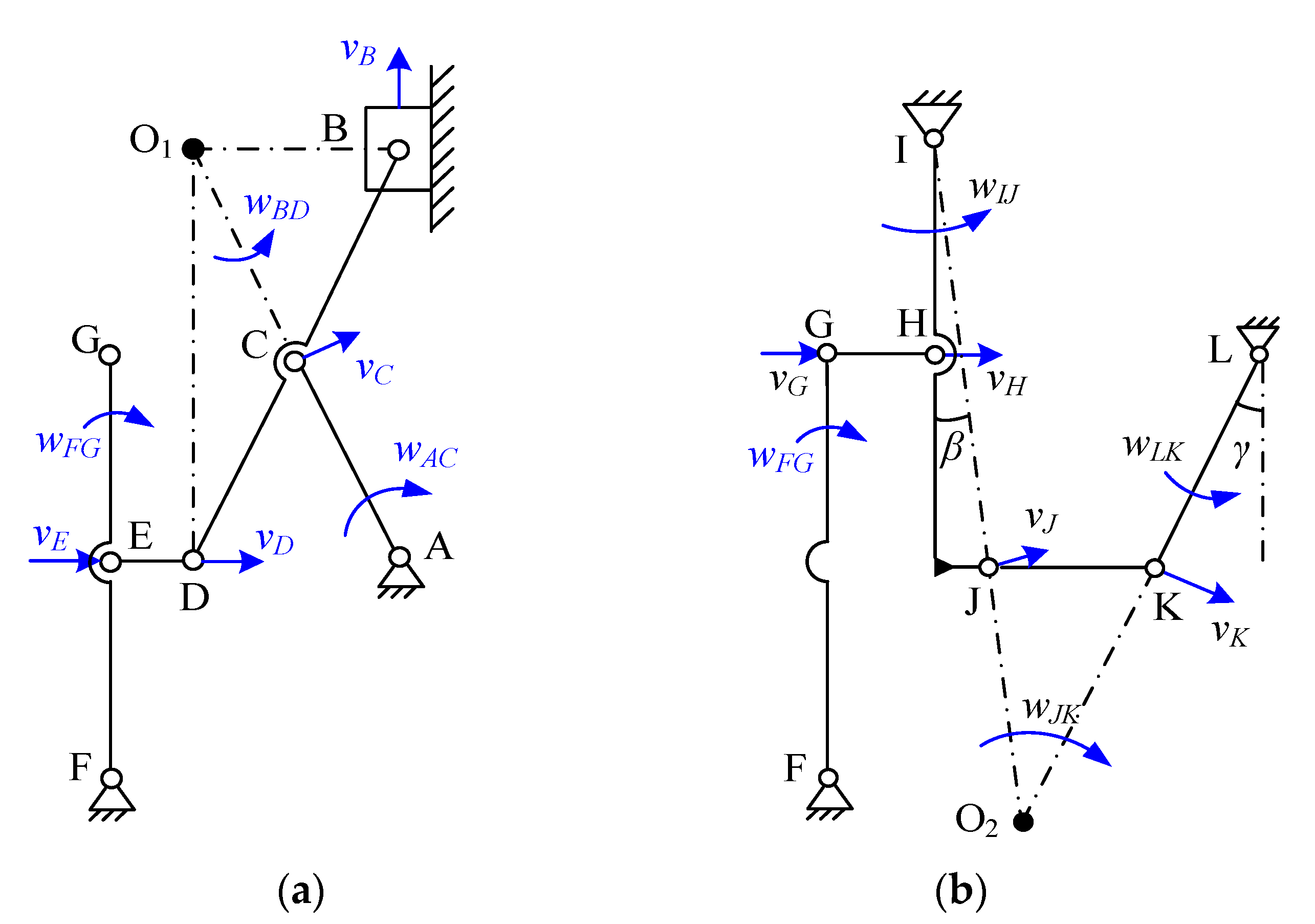
3.1. The Kinematic Modeling

Based on the velocity diagram of the half RA-DFM in Figure 2, the velocity response of each flexure hinge is analyzed under the action of the input velocity vB. It is obvious that the linkages AC, FG and IJ rotate around their revolute joints A, F and I; the linkage LK rotates around the assumed center L. According to the input and output velocity directions, the linkages BD and JK rotate with O1 and O2, respectively. Considering the small deformation of the whole system, the velocity directions of the linkages are seen as constant, so the linkage DE generates pure translational movement similar to linkage GH. The velocities of revolute joints B–K can be obtained as follows:
v B = w B D l O 1 B
v C = w B D l O 1 C = w A C l A C
v D = v E = w B D l O 1 D = w F G l E F
v G = v H = w F G l F G = w I J l I H
v J = w I J l I J = w J K l O 2 J
v K = w J K l O 2 K = w L K l L K
where lAC, lEF, lFG, lIH, lIJ, lJK and w B D , w A C , w F G , w I J , w J K , w L K are the length and angular velocity of the corresponding linkages, respectively. l O 1 B , l O 1 C , l O 1 D , l O 2 J , l O 2 K and l L K are the rotation radii of the corresponding revolute joints, which could be easily calculated using the sine theorem of triangles.
The rotational angles of flexure hinges are analyzed with the input displacement y B . In order to clearly describe the rotational deformation, the amplification ratios of the EDSR and LTMs are calculated using a simplified analytical model [21].
a m p E D S R = l A B l A D
a m p L T M l o w = l F G l E F
a m p L T M u p = l I J l I H
where lAB and lAD are the distance of revolute joins A, B and A, D, respectively.
As shown in Figure 4, the linkages AC, BD, FG, IJ, JK and KL generate rotation angles δ1, δ2, δ3, δ4, δ5 and δ6, respectively, and the rotation of linkages DE and GH are ignored for the approximate translational motion. Based on the formula of arc length, the rotation angles of revolute joints A–L are calculated using the following equations:
φ A = δ 1 = y B l A D
φ C = δ 1 + δ 2 = 2 y B l A D
φ B = φ D = δ 2 = y B l A D
φ E = φ F = φ G = δ 3 = a m p E D S R y B l E F
φ H = φ I = δ 4 = a m p E D S R a m p L T M l o w y B l I H
φ J = δ 4 + δ 5 = a m p E D S R a m p L T M l o w y B l I H + a m p E D S R a m p L T M l o w a m p L T M u p y B l O 2 J
φ K = δ 5 + δ 6 = a m p E D S R a m p L T M l o w a m p L T M u p y B l O 2 J + a m p E D S R a m p L T M l o w a m p L T M u p y B l L K cos γ
φ L = δ 6 = a m p E D S R a m p L T M l o w a m p L T M u p y B l L K cos γ
Based on the above analysis, the rotational deformation of the assumed revolute joint L is the final output angle of the RA-DFM, which is expressed in Equation (17). The output angle is affected by the total amplification ratio, the arm length of the output platform and the input displacement.

3.2. The Output of Piezoelectric Ceramic

The actual output displacement of piezoelectric ceramic is related to the external stiffness; thus, the input stiffness of RA-DFM is firstly modeled. Assuming an input displacement yB is applied on the input end, the generated force of the DLPH and torques of the right circular flexure hinges A~L are:
F D L P H y = k D L P H y y B
M r i = K r i φ i        i = A ~ L
where kDLPHy is the translational stiffness of DLPH in the Y direction, and K D L P H y = 4 E b l o w t D L P H 3 l D L P H 3 [21]. blow, tDLPH and lDLPH are the width, thickness and length of the leaf spring hinge in the DLPH, respectively. Kri is the rational stiffness of flexure hinges A~L, and K r i = 9 π r R i 1 / 2 2 E b i t R i 5 / 2 - 1 for the right circular hinges A–K [21]. b, rR and tR are the width, radius and thickness of the right circular hinge, respectively. It is noted b = blow for the right circular hinge in the lower mechanism, and b = bup for the right circular hinge in the upper mechanism.
The revolute joint L is simplified from the FSM, which includes two leaf spring hinges. The compliance matrix of flexure hinges has been widely applied to analyze the stiffness of flexible mechanisms [12,21,22,23]; thus, it is used to model the rotational stiffness of the revolute joint L in this paper. As shown in Figure 5, the local coordinates of leaf spring hinges are expressed as oi-xiyizi, and the global coordinate O0-X0Y0Z0 is defined in the center of the output platform. The compliance matrix of the leaf spring hinge in the local coordinate is expressed as
C 0 = l F S M E b u p t F S M 0 0 0 0 0 0 4 l F S M 3 E b u p t F S M 3 0 0 0 6 l F S M 2 E b u p t F S M 3 0 0 4 l F S M 3 E b u p 3 t F S M 0 6 l F S M 2 E b u p 3 t F S M 0 0 0 0 l F S M G k 2 b u p t F S M 3 0 0 0 0 6 l F S M 2 E b u p 3 t F S M 0 12 l F S M E b u p 3 t F S M 0 0 6 l F S M 2 E b u p t F S M 3 0 0 0 12 l F S M E b u p t F S M 3
where lFSM, tFSM and bup are the length, thickness and width of the leaf spring hinge in the FSM, respectively. E and G are the Young’s modulus and shear modulus of the material, respectively. k2 is a geometric parameter, and k2 = bup/tFSM.
In order to obtain the compliance model of the FSM in the global coordinate O0-X0Y0Z0, the local compliance matrices of the two leaf spring hinges are transferred to the global coordinate.
C F S M = i = 1 2 R i 0 0 R i I P i T 0 I C 0 I 0 P i I R i T 0 0 R i T
where Pi and Ri are the translational and rotational matrices, respectively, from the local coordinate to the global coordinate. For the ith flexure hinge, P i = 0 r i z r i y r i z 0 r i x r i y r i x 0 ,   r i = o i O 0 = r i x r i y r i z is the vector from the origin oi to the global origin O0 in the local coordinate oi-xiyizi. Ri is the rotation matrix of the coordinate oi-xiyizi with respect to O0-X0Y0Z0, and the rotation matrices about the X, Y and Z axis are R x ( θ x ) = 1 0 0 0 cos θ x sin θ x 0 sin θ x cos θ x , R y ( θ y ) = cos θ y 0 sin θ y 0 1 0 sin θ y 0 cos θ y and R z ( θ z ) = cos θ z sin θ z 0 sin θ z cos θ z 0 0 0 1 , respectively.
The relationship between the deformation and the applied force on the FSM is
F = C F S M 1 S
where S = X 0 , Y 0 , Z 0 , θ X 0 , θ Y 0 , θ Z 0 and F = F X 0 , F Y 0 , F Z 0 , M X 0 , M Y 0 , M Z 0 .
According to the simplification rule of the revolute join L, the rotation direction of the revolute join L is the θZ0 direction of the FSM, and considering the symmetry of the FSM, the rotational stiffness of L is half of the rotational stiffness of FSM in the θZ0 direction, which could be calculated via M Z 0 / θ Z 0 ; it is also the 6th × 6th element of C F S M 1 based on Equation (22).
K r L = C F S M 1 6 , 6 / 2
The flexible mechanism is a stable system after an input force FyB from the piezoelectric actuator is applied on the input end; the generated displacement on the input end is yB and the angular deformation of each joint is listed in Equations (10)–(17). Based on the principle of virtual work, the total virtual work of the system is zero if a virtual displacement ΔyB is applied on the system.
Δ W = F y B Δ y B + F D L P H y Δ y B + 2 i = A L M r i Δ φ i = 0        i = A ~ L
where the first term denotes the virtual work caused by the input force FyB and the virtual displacement Δ y B . The second term denotes the virtual work of the DLPH due to the deformation of DLPH and elastic force FDLPHy. As shown in Figure 6, the third term is the virtual work caused by torsional springs with rotary torque Μ r i and virtual angular deformation Δ φ i . The relationships between Δ φ i and Δ y B are same as those between φ i and y B .
Substitute Equations (18) and (19) into Equation (24), and the input stiffness of the RA-DFM in the Y direction is obtained.
K i n Y = F y B / y B
Generally, the piezoelectric ceramic could be seen as a spring with constant stiffness, and the flexible mechanism acts as the load for the piezoelectric ceramic. Based on the Hooke’s law, the actual output of piezoelectric ceramic is reduced according to
y a p z t = K p z t K p z t + K i n Y y n p z t
where Kpzt and Snpzt are the stiffness and nominal output of piezoelectric ceramic, respectively.

3.3. The Stress Analysis

In order to guarantee the repeatability and durability of the RA-DFM, the maximal stress of the flexure hinges must be less than the allowable stress of the material. According to the kinematic analysis, the leaf spring hinges and right circular hinges mainly generate translational deformation and rotational deformation, respectively. Based on the stress analysis in Ref. [24], the maximum stress of each can be expressed as follows:
σ l e a f - m a x = 3 k l Δ E t l e a f l l e a f 2
σ r c h - m a x = 6 k c Κ r φ b t R 2
where kc and kl are the stress concentration factor of the right circular hinge and leaf spring hinge, respectively. Δ and φ are the translational displacement of a leaf spring hinge and the angular deformation of a right circular hinge, respectively.

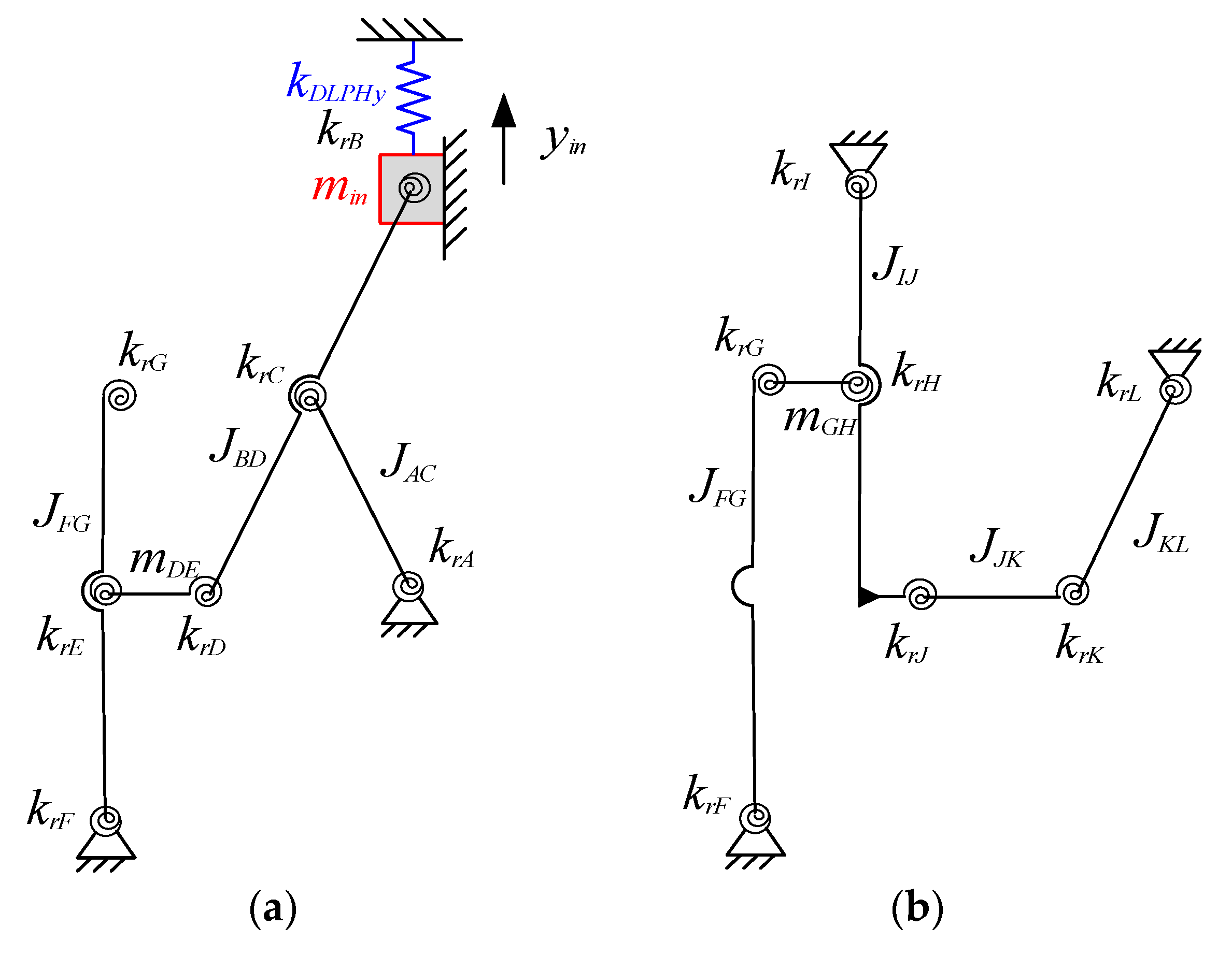
3.4. The Dynamic Modeling

In order to maximize the working frequency of a rotary actuator, the first resonant mode is better along the working direction because far less working frequency is usually required compared to the first resonant frequency to avoid activating the resonant vibration. Therefore, the first mode shape of the RA-DFM is designed to be the rotation of the output platform, which is also the translation in the Y direction for the input end. The Lagrange equation is applied for the modeling of the resonant frequency.
d d t T y ˙ i n U y i n = 0
where T and U are the total kinetic energy and elastic potential energy, respectively. yin is the assumed input displacement.
The dynamic model of the half RA-DFM is shown in Figure 6; the flexure hinges are simplified as torsional springs with constant stiffness. It is noted that only planar motion is considered in the dynamic model due to the high rigidity of the flexure hinges in the out-of-plane configuration. Based on the velocity and deformation analysis in Section 3.1, when an input displacement yin is enacted on the input end, the total kinetic energy of the system is expressed as
T = 1 2 m i n y ˙ i n 2 + m D E v D 2 + m G H v G 2 + + J i w i 2          i = A C , B D , F G , I J , J K , K L
where min, mDE and mGH are the masses of the input end and linkages DE and GH, respectively. Ji is the rotational inertia of the linkage i. wi is the angular velocity of the linkage i, which is also the first-order derivative of φ i .
Potential energy mainly results from the deformation of the flexure hinges. The total potential energy of the system can be expressed as
U = 1 2 K D L P H y y i n 2 + i = A L K r i φ i 2          i = A L
Substitute Equations (30) and (31) into (29) and transfer it to the standard dynamic equation M i n Y y ¨ i n + K i n Y y i n = 0   . Based on the theory of vibrations and the dynamic equation, the first resonant frequency of RA-DFM can be obtained using the characteristic equation:
f 1 = K i n Y / M i n Y 2 π  
where Min-Y is the equivalent mass of the RA-DFM in the input end.

4. The Optimization

According to the above analyses, the performance of the RA-DFM is significantly affected by the geometric parameters; thus, it is necessary to conduct mechanical optimization to improve the static and dynamic characteristics. A large output range is able to extend the application, which is related to both the geometric parameter and the input displacement according to Equation (17). This section focuses on the maximization of the output range through optimizing the geometric parameters. The objective function is expressed as:
F max = a m p E D S R a m p L T M l o w a m p L T M u p l L K cos γ
Considering the stress, output of piezoelectric ceramic, resonant frequency, structure compactness and machining accuracy of the RA-DFM, the constraint conditions for the optimization are given as follows:
(1) Maximum stress: As mentioned previously, the maximum stresses occur at the surface of the leaf spring hinge and/or the minimal thickness of the fight circular hinge. Both of the maximum stresses should be lower than the allowable stress of the material.
σ leaf max σ m / s f σ r c h - m a x σ m / s f
where σm is yield strength, and it is about 400 MPa for the aluminum alloy 7075-T6, which has been widely applied as the material of the flexible mechanism. sf is the safety factor and has been chosen as 1.2.
(2) Input stiffness: According to Equation (26), a smaller input stiffness could improve the actual output of the piezoelectric actuator; thus, the input stiffness of the RA-DFM is limited in the following condition based on the stiffness of the ordinary commercial piezoelectric actuator:
K i n Y 2   N / μ m
(3) First resonant frequency and mode shape: The first resonant frequency of the developed mechanism decides the working frequency; thus, the low-limit frequency of the RA-DFM is restrained to guarantee the working bands.
f 1 200   Hz
The resonant mode shape of the FSM in the vertical direction (Y0 direction) is possible to activate due to compliance. In order to guarantee the rotational motion is the first mode shape, the resonant frequency of the FSM in the Y0 direction is required to be larger than that in the rotational direction.
C F S M 1 2 , 2 / m F S M 2 π C F S M 1 6 , 6 / J F S M 2 π
where mFSM and JFSM are the mass and rotational inertia of the moving platform in the FSM, respectively.
(4) Machining accuracy and structure compactness: To guarantee the machining accuracy and the material buckling of the leaf spring hinge and right circular hinge, it is feasible to choose 0.05 t R / r R 0.65 , l D L P H 15 t D L P H and l F S M 15 t F S M . Considering the assembly of the upper and lower mechanism, it is better to satisfy l E G = l H J = l A B / 2 . Further, taking the theoretical modeling precision and structural compactness into account, the ranges of the variables are chosen as the third column of Table 1.
As listed in the first column of Table 1, the variables mainly include geometrical sizes of the right circular hinge, leaf spring hinge and the linkage lengths of the amplification mechanisms. The optimization process is conducted using the “fmincon” function in Matlab software, which is used to find local minima. Therefore, the optimization objective adopts the negative of Equation (33), and several different groups of original values in the defined ranges are selected to break the local optimization. After many attempts, for the smallest value of the objective function, the corresponding original values and approximative optimization results are obtained and shown in Table 1.

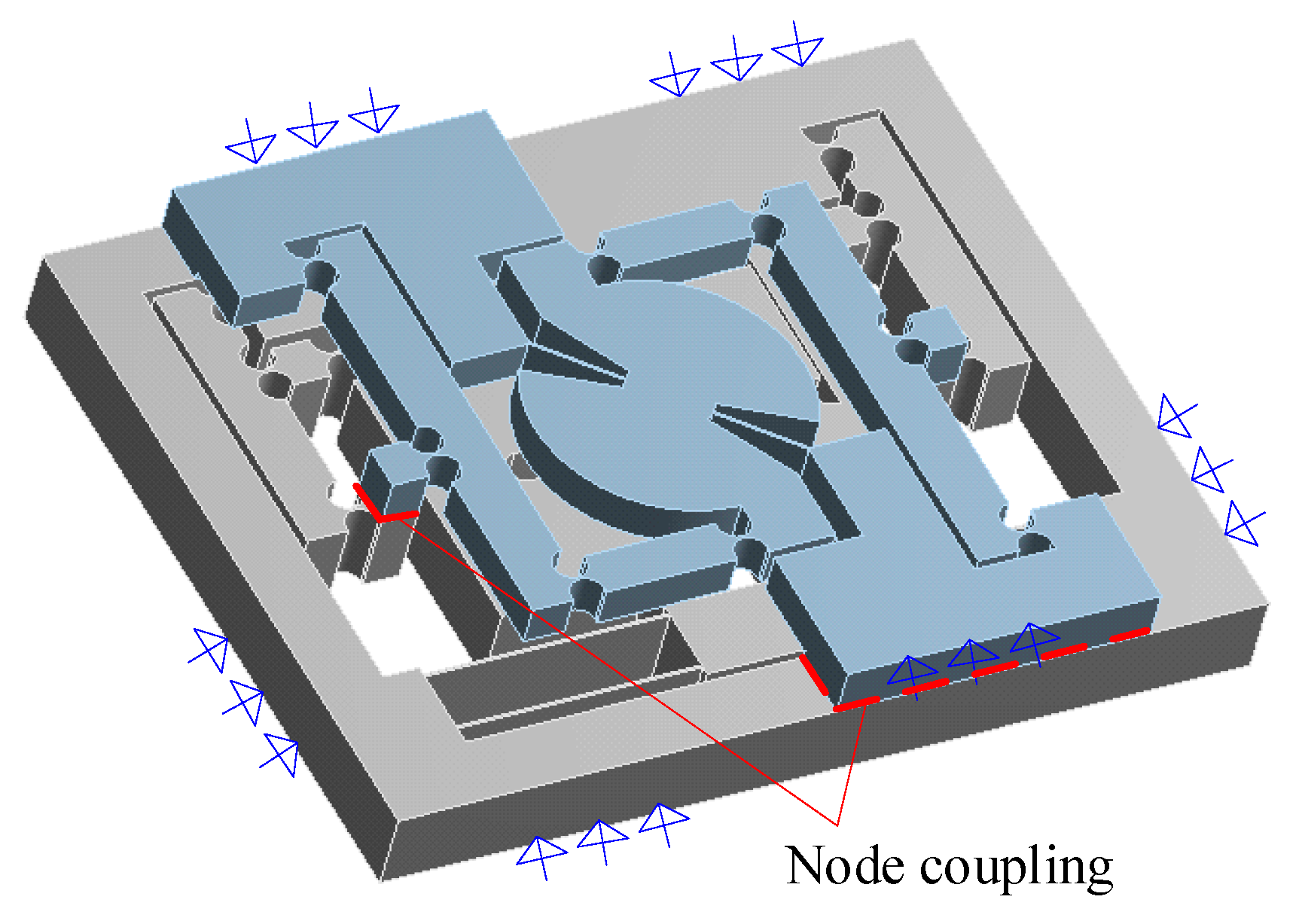
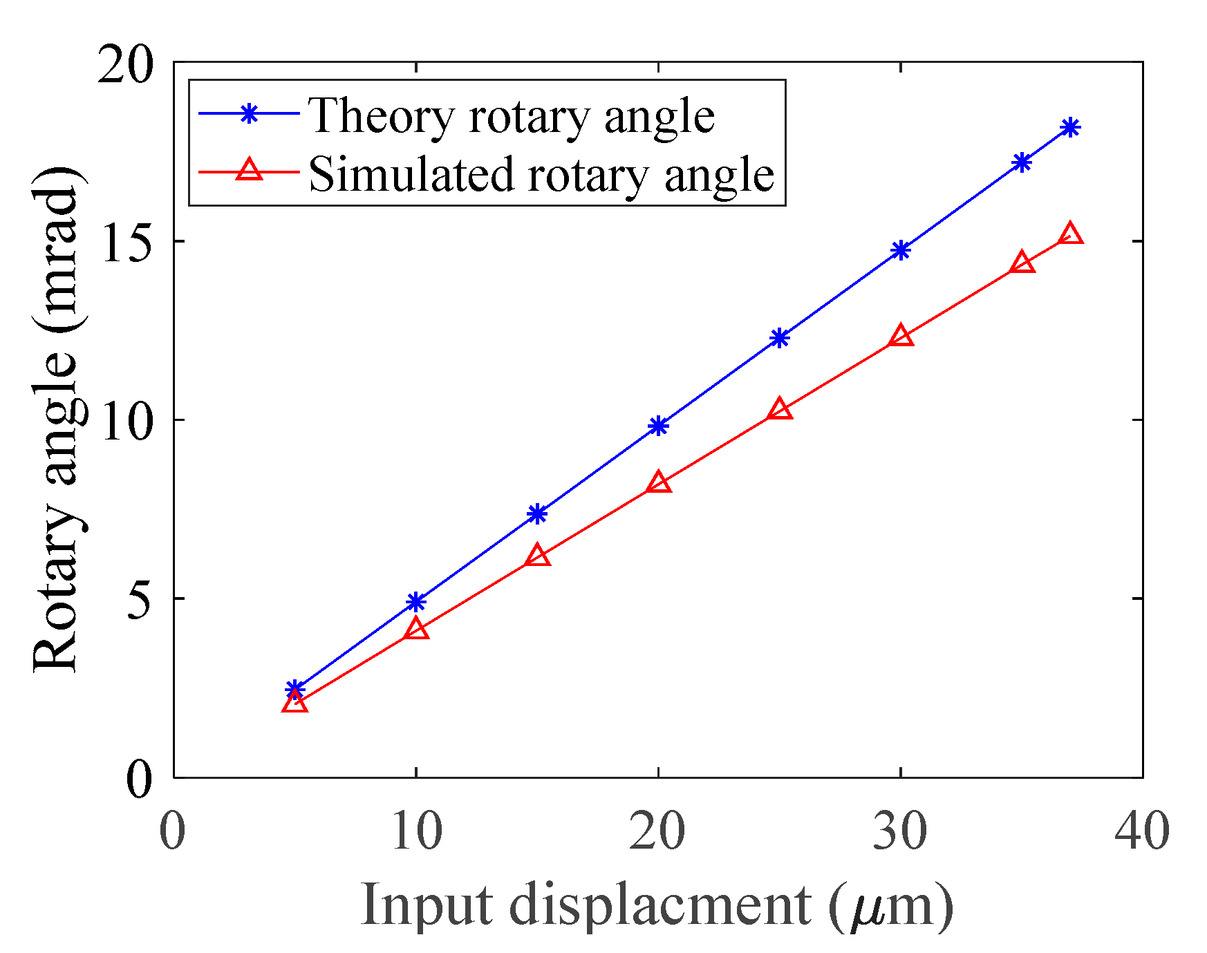
5. The Finite Element Analysis of RA-DFM

In the FEA modeling of the RA-DFM, the lower and the upper mechanisms are firstly modeled separately based on the optimized parameters, which are then formed into a new part in Workbench software to couple the nodes between the related bases and connecting blocks, and the threaded connections are simplified as rigid connections to reduce the structure complexity. Aluminum alloy is selected as the material, with Young’s modules E = 71 GPa, density ρ = 2770 kg/m3 and Poisson’s ratio ν = 0.33. The RA-DFM is meshed using the adaptive method with 0.5 mm element size; the whole mechanism is meshed in 347,947 elements. The surrounding surfaces are completely fixed in the following simulation, as shown in Figure 7.
An input force Fin = 10 N is applied on the input end in the Y direction to examine the input stiffness of the RA-DFM; the total deformation is shown in Figure 8. The input end translates in the Y direction by 5.83 μm, and the output platform generates a rotary angle as in the design. The input stiffness of RA-DFM is calculated as 1.71 N/μm, and the modeling error is 2.34% compared with the theoretical result of 1.75 N/μm, indicating the correctness of the theoretical model. In order to guarantee the output of the piezoelectric ceramic, the stiffness of the piezoelectric ceramic is preferred to exceed 10 times that of the external mechanism.
The space reserved for the piezoelectric ceramic is 13 × 10 × 43.11 mm, which is suitable for commercial piezoelectric ceramic (MTP150/7 × 7/36, Coremorrow, Harbin, China). The nominal output displacement and stiffness are 38 μm and 50 N/μm, respectively. Based on Equation (24), the actual output of the selected piezoelectric ceramic is about 37 μm. A series of inputs yin = [5, 10, 15, 20, 25, 30, 35, 37] μm is used to assess the output property. As shown in Figure 9 and Table 2, the output rotary angle is almost linear to the input displacement, and the total simulated amplification ratio of the RA-DFM is about 8.42, which is obviously less than the theoretical calculation of 10.10. The separate amplification ratios of the three amplification mechanisms are simulated as 1.78, 2.82 and 1.67, respectively. The largest modeling error occurs at the EDSR mechanism; it is because the rest of the flexible mechanisms generate a large load on the output terminal of the EDSR mechanism, which leads to serious deformation of the right circular hinges A and C in the X direction as well as the rotation. In addition, the linkages of the EDSR generate much more deformation compared to the lever-type mechanism.
For the input placement yin = 37 μm, the horizontal displacement generated on flexure hinge K is 296.46 μm, leading to a rotary angle of 15.14 mrad. Furthermore, the position of the output platform center is extracted to assess the drift of the rotational center. The total displacement change of the center is about 1.29 μm, which only accounts for 0.44% of the rotary displacement, showing the excellent rotational accuracy. In addition, the maximum stress of 194.08 MPa occurred at the circular hinge K in the FEA; it is because the stress of the circular hinge is positively correlated to the angle deformation. Flexure hinge K generates the largest deformation according to Equations (10)–(17). According to Equation (34), the simulated maximum stress is far less than the allowable yield stress of 333.33 Mpa for aluminum alloy 7075-T6, which indicates that the designed RA-DFM could work normally in this situation.
The modal simulation of the RA-DFM is also implemented, and the first three mode shapes are shown in Figure 10. It shows that the first mode shape is the rotation of the output platform in the θZ direction with the resonant frequency 192.45 Hz, which coincides well with the design objective. The modeling error is 1.61% compared with the theoretical calculation. The second mode shape is the translation in the Y0 direction of the FSM with the resonant frequency 240.47 Hz, which is 24.95% larger than the first resonant frequency; this is mainly caused by the stiffness difference of the FSM in the θZ0 and Y0 directions. The third mode shape is out of the plane with the resonant frequency 642.43 Hz, which is about 3.34 times the first resonant frequency; it means the third mode shape is hard to activate in low-frequency operation.

6. Conclusions

A single piezoelectric-driven rotary actuator including a double-layer flexible mechanism was proposed in this paper. The actuator integrated an EDSRM and an LTM to amplify the output displacement of the piezoelectric ceramic in the lower mechanism. The rotational motion was generated on the upper mechanism as well as the third displacement amplification. The rotation angle of the mobile platform, actual output of the piezoelectric ceramic, maximal stress and first resonant frequency of the RA-DFM were theoretically modeled, and they were utilized to optimize the geometrical parameters.
The numerical models were validated to be efficient at predicting properties using the FEA method. According to the simulation results, the proposed RA-DFM possesses an amplification ratio of 8.42 and a first resonant frequency of 192.45 Hz. With 37 μm input displacement, the maximum stress of the RA-DFM is 194.08 MPa, and the maximal rotational angle of the output platform is 15.14 mrad with 0.44% center drift, showing excellent output properties.

Author Contributions

Conceptualization, Z.G. and Y.T.; methodology, Z.G. and P.Z.; software, P.Z. and W.Z.; validation, P.Z. and W.Z.; formal analysis, W.Z. and G.H.; investigation, Z.G., P.Z. and W.Z.; resources, Z.G. and Y.T.; data curation, G.H.; writing—original draft preparation, Z.G., P.Z. and W.Z.; writing—review and editing, G.H. and Y.T.; project administration, Z.G. and Y.T.; funding acquisition, Z.G. and Y.T. All authors have read and agreed to the published version of the manuscript.

Funding

This research was supported by the “National Natural Science Foundation of China (No. 52205138)”, “Guangdong International Cooperation Program of Science and Technology (No. 2022A0505050078)”, “Open Fund of State Key Laboratory of Precision Electronic Manufacturing Technology and Equipment, Guangdong University of Technology (No. JMDZ2021001)” and “Fundamental Research Funds for the Central Universities, CAUC (No. 3122019095)”.

Data Availability Statement

Not applicable.

Conflicts of Interest

The authors declare no conflict of interest.

References

  1. Habibullah, H. 30 Years of atomic force microscopy: Creep, hysteresis, cross-coupling, and vibration problems of piezoelectric tube scanners. Measurement 2020, 159, 107776. [Google Scholar] [CrossRef]
  2. Wei, Y.; Xu, Q. Design and Testing of a New Force-Sensing Cell Microinjector Based on Soft Flexure Mechanism. IEEE Sens. J. 2019, 19, 6012–6019. [Google Scholar] [CrossRef]
  3. Qin, Y.; Soundararajan, R.; Jia, R.; Huang, S. Direct inverse linearization of piezoelectric ceramic’s initial loading curve and its applications in full-field optical coherence tomography (FF-OCT). Mech. Syst. Signal Process. 2021, 148, 107147. [Google Scholar] [CrossRef]
  4. Zhang, Z.; Yang, X.; Yan, P. Large dynamic range tracking of an XY compliant nanomanipulator with cross-axis coupling reduction. Mech. Syst. Signal Process. 2019, 117, 757–770. [Google Scholar] [CrossRef]
  5. Wang, T.; Li, Y.; Zhang, Y.; Lin, R.; Qain, J.; Dou, Z. Design of a flexure-based parallel XY micropositioning stage with millimeter workspace and high bandwidth. Sens. Actuators A Phys. 2021, 331, 112899. [Google Scholar] [CrossRef]
  6. Bazaei, A.; Ettefagh, M.; Chen, Z. Displacement amplification and differential actuation in piezo driven nanopositioners. Mech. Syst. Signal Process. 2021, 151, 107356. [Google Scholar] [CrossRef]
  7. Lyu, Z.; Wu, Z.; Xu, Q. Design and development of a novel piezoelectrically actuated asymmetrical flexible microgripper. Mech. Mach. Theory 2022, 171, 104736. [Google Scholar] [CrossRef]
  8. Baek, S.; Cho, N.; Lee, D. Fabrication of a piezoelectrically driven micropositioning 3-DOF stage with elastic body using a multi-material 3D printer. Rapid Prototyp. J. 2020, 26, 1579–1591. [Google Scholar] [CrossRef]
  9. Wang, R.; Zhang, X. Optimal design of a planar parallel 3-DOF nanopositioner with multi-objective. Mech. Mach. Theory 2017, 112, 61–83. [Google Scholar] [CrossRef]
  10. Zhan, W.; He, X.; Yang, J.; Lai, J.; Zhu, D. Optimal design method for 3-DOF planar compliant mechanisms based on mapping matrix constraints. Structures 2020, 26, 1–5. [Google Scholar] [CrossRef]
  11. Al-Jodah, A.; Shirinzadeh, B.; Ghafarian, M.; Das, T.; Pinskier, J. Design, modeling, and control of a large range 3-DOF micropositioning stage. Mech. Mach. Theory 2021, 156, 104159. [Google Scholar] [CrossRef]
  12. Kim, H.; Gweon, D. Development of a compact and long range XYθz nano-positioning stage. Rev. Sci. Instrum. 2012, 83, 085102. [Google Scholar] [CrossRef] [PubMed]
  13. Kang, S.; Lee, M.; Choi, Y. Six Degrees-of-Freedom Direct-Driven Nanopositioning Stage Using Crab-Leg Flexures. IEEE/ASME Trans. Mechatron. 2020, 25, 513–525. [Google Scholar] [CrossRef]
  14. Lee, M.; Park, E.; Yeom, J.; Hong, D.; Lee, D. Pure Nano-Rotation Scanner. Adv. Mech. Eng. 2012, 4, 962439. [Google Scholar] [CrossRef]
  15. Zhu, X.; Wen, Z.; Chen, G.; Liang, J.; Liu, P. A decoupled flexure-based rotary micropositioning stage with compact size. Proc. Inst. Mech. Eng. Part C J. Mech. Eng. Sci. 2018, 232, 4167–4179. [Google Scholar] [CrossRef]
  16. Clark, L.; Shirinzadeh, B.; Zhong, Y.; Tian, Y.; Zhang, D. Design and analysis of a compact flexure-based precision pure rotation stage without actuator redundancy. Mech. Mach. Theory 2016, 105, 129–144. [Google Scholar] [CrossRef]
  17. Yang, Z.; Zhou, X.; Huang, H.; Dong, J.; Fan, Z.; Zhao, H. On the Suppression of the Backward Motion of a Piezo-Driven Precision Positioning Platform Designed by the Parasitic Motion Principle. IEEE Trans. Ind. Electron. 2020, 67, 3870–3878. [Google Scholar] [CrossRef]
  18. Chang, Q.; Liu, Y.; Deng, J.; Zhang, S.; Chen, W. Design of a precise linear-rotary positioning stage for optical focusing based on the stick-slip mechanism. Mech. Syst. Signal Process. 2022, 165, 108398. [Google Scholar] [CrossRef]
  19. Sun, X.; Chen, W.; Zhang, J.; Zhou, R.; Chen, W. A novel piezo-driven linear-rotary inchworm actuator. Sens. Actuators A Phys. 2015, 224, 78–86. [Google Scholar] [CrossRef]
  20. Song, S.; Shao, S.; Xu, M.; Shao, Y.; Tian, Z.; Feng, B. Piezoelectric inchworm rotary actuator with high driving torque and self-locking ability. Sens. Actuators A Phys. 2018, 282, 174–182. [Google Scholar] [CrossRef]
  21. Guo, Z.; Zhang, W.; Tian, Y.; Zhang, Z.; Cao, Y.; Lu, X.; Zhang, T. Design, modeling, and testing of a one degree of freedom manipulator with three stage amplification mechanism. Rev. Sci. Instrum. 2022, 93, 123705. [Google Scholar] [CrossRef] [PubMed]
  22. Liu, Y.; Zhang, Z. A large range compliant XY nano-manipulator with active parasitic rotation rejection. Precis. Eng. 2021, 72, 640–652. [Google Scholar] [CrossRef]
  23. Yuan, L.; Wang, L.; Qi, R.; Zhao, Z.; Jin, J.; Zhao, C. A novel hollow-type XY piezoelectric positioning platform. Int. J. Mech. Sci. 2023, 255, 108496. [Google Scholar] [CrossRef]
  24. Duan, Y.; Ou, K.; Sun, Y.; Tian, Y. Stress Analysis of the Circular Arc Flexure Hinge. J. Mech. Transm. 2016, 40, 148–170. [Google Scholar]
Figure 1. Mechanical design of the RA-DFM: (a) the assembly diagram; (b) the lower mechanism; (c) the upper mechanism.
Actuators 12 00231 g001
Figure 2. The velocity diagram of half RA-DFM: (a) the lower stage; (b) the upper stage.
Actuators 12 00231 g002
Figure 3. The velocity diagram of the connecting block with unaligned rotation centers in the LTMlow and LTMup.
Actuators 12 00231 g003
Figure 4. The deformation diagram of half RA-DFM: (a) the lower stage; (b) the upper stage.
Actuators 12 00231 g004
Figure 5. The miniature output platform and FSM.
Actuators 12 00231 g005
Figure 6. The dynamic model of half RA-DAFM: (a) the lower stage; (b) the upper stage.
Actuators 12 00231 g006
Figure 7. The FEA model of the RA-DFM.
Actuators 12 00231 g007
Figure 8. The deformation of the RA-DFM with input force 10 N.
Actuators 12 00231 g008
Figure 9. The output comparison of the theoretical and simulation results with different input displacement.
Actuators 12 00231 g009
Figure 10. The first three mode shapes of RA-DFM: (a) the first mode shape; (b) the second mode shape; (c) the third mode shape.
Actuators 12 00231 g010
Table 1. The key sizes of RA-DFM.
VariablesOriginal Values (mm)Ranges (mm)Optimization Results (mm)
blow12.00[10, 15]10.00
bup8.00[5, 10]5.00
tDLPH0.5[0.3, 1]0.30
lDLPH15[10, 30]30.00
lAB40[30, 50]41.11
lAD20[15, 30]20.00
lFG40[30, 50]31.45
lIJ40[30, 50]49.54
tFSM0.5[0.3, 1]0.30
lFSM15[10, 30]10.98
lJK15[10, 20]20.00
rR1[0.5, 2]2.00
tR0.5[0.3, 1]0.30
Table 2. The comparison of the theoretical and simulation results.
a m p E D S R a m p L T M - l o w a m p L T M - u p Kin-Yf1
Theoretical calculation2.052.881.711.75 N/μm189.35 Hz
Simulation results1.782.821.681.71 N/μm192.45 Hz
Modeling error15.16%2.13%1.79%2.34%1.61%
Disclaimer/Publisher’s Note: The statements, opinions and data contained in all publications are solely those of the individual author(s) and contributor(s) and not of MDPI and/or the editor(s). MDPI and/or the editor(s) disclaim responsibility for any injury to people or property resulting from any ideas, methods, instructions or products referred to in the content.

