Article

Dynamic Response Analysis of the Bi-Tandem Axial Piston Pump with Dual-Loop Positive Flow Control under Pressure Disturbance

1
College of Mechanical and Electronic Engineering, Shandong University of Science and Technology, Qingdao 266590, China
2
College of Information Science and Engineering, Shandong Normal University, Jinan 250358, China
*
Author to whom correspondence should be addressed.
Actuators 2023, 12(7), 260; https://doi.org/10.3390/act12070260
Submission received: 12 May 2023 / Revised: 20 June 2023 / Accepted: 22 June 2023 / Published: 25 June 2023
(This article belongs to the Special Issue Flow Control Actuators and Their Diverse Fluid Dynamic Applications)

Abstract

:
The bi-tandem axial piston pump is an indispensable powerhouse in high-pressure and high-power engineering hydraulic systems, with its output flow response characteristics under pressure disturbance exerting a significant influence on the working process of double pumps. Unfortunately, the stability of the original single-loop mechanical–hydraulic servo control system is sensitive to unpredictable interference. To alleviate this quandary, this paper proposes a dual-loop positive flow control method for the flow control of the bi-tandem axial piston pump, establishes a mathematical model of the bi-tandem axial piston pump with dual-loop positive flow control, and establishes a simulation model based on Simulink. The validity of the model is verified by experiments. The performance advantages of the dual-loop positive flow control method relative to the single-loop positive flow control method are analyzed. The results show a faster response speed and smaller steady-state error with the dual-loop method, which performs better than the original single-loop positive flow control. Furthermore, the study examines the influence of different forms, degrees, and directions of pressure disturbance on the dynamic response characteristics of the bi-tandem axial piston pump. Symmetric pressure disturbance results in an increase in the maximum relative error of the output flow proportional to its degree. Notably, the influence of asymmetric pressure disturbance on the output flow of the double pumps possesses characteristics of a superimposable nature, and the steady-state value of the output flow is highly dependent on superimposed pressure disturbance and less affected by the action time point of asymmetric pressure disturbance. Further, the unloading pressure disturbance exerts less influence on the system compared to the loading pressure disturbance. This paper provides valuable insights into improving the response speed and control accuracy of bi-tandem axial piston pumps equipped with positive flow control.

1. Introduction

The hydraulic drive system has higher power density than the electric drive system and mechanical drive system, so it is widely used in high-power engineering and mobile machinery, such as excavators, loaders, and cranes [1,2,3]. The valve control system, an integral component of hydraulic systems, presents numerous advantages, such as fast response, high precision, and simple circuits, but the presence of throttling losses and energy consumption remains a significant disadvantage [4,5,6]. A more energy-efficient alternative to the valve control system is the pump control system, which provides greater potential for energy savings. Specifically, the variable axial piston pump serves as a crucial power source and flow control mechanism within high-power pump-controlled hydraulic systems [7,8]. Positive flow control, a prevalent method for flow regulation in variable axial piston pumps, guarantees the control accuracy and stability of the system while decreasing energy loss and improving system efficiency through accurate control of output flow. As a result, positive flow control holds tremendous promise for broad applications in engineering machinery.
The exceptional dynamic response performance of a piston pump can effectively accommodate system changes, optimize flow output, and even enhance system efficiency. However, the dynamic response of the piston pump is frequently hindered by stability issues caused by pressure disturbances that significantly impede the accurate control of output flow and smooth operation. Consequently, the investigation of the dynamic characteristics and variable dynamic response of the piston pump has become a crucial topic in the field of hydraulic drive. Ivantysynova and Grabbel et al. [9,10] developed a basic dynamics model of a pump-controlled system based on a pump-controlled cylinder, in which a simplified swash plate moment calculation was considered, and the results refuted the prejudice that the dynamic response of the pump-controlled systems was generally slow. Bergada et al. [11] established a mathematical model of an axial piston pump considering swash plate inclination, leakage clearance, rotational speed, and damping grooves, which more accurately modeled the pressure distribution characteristics in the flow distribution region during motion, analyzed the pressure distribution and flow leakage between the barrel and port plate and the force and torque of the barrel, and predicted the bimodal peaks of torque fluctuation.
Cui et al. [12] established a mathematical model of the load-sensitive pump, studied the influence of the structural parameters and damping hole parameters of the pump on the system response through dynamic simulation, and optimized the response characteristics of the load-sensitive pump. Du et al. [13] proposed a variable oil supply pressure valve-controlled hydraulic drive method based on load prediction. This method tracks the pressure required by any actuator branch by changing the oil supply pressure. The load-sensitive system achieves the same response speed as the electro-hydraulic control system with valve-controlled actuators. Gao et al. [14] analyzed the dynamic performance of an asymmetric axial piston variable pump through simulation and used a servo proportional valve and an angular displacement sensor to form an angular feedback control to achieve swash plate control of an asymmetric axial piston variable pump. This method can reduce or eliminate the throttling loss and provide a significant energy-saving effect. Hasan et al. [15] carried out a dynamic analysis and state estimator design for the pedagogical hydraulic system by system inversion, analyzed its transient and steady-state response, and then designed a state estimator for variable loads to achieve a good estimation of the system state with minimum sensors.
Li et al. [16] established a dynamic model of a servo-hydraulic cylinder system based on the theory of nonlinear dynamics and studied the nonlinear dynamic characteristics of the servo-hydraulic cylinder. He and Huang et al. [17,18,19] proposed a variable displacement asymmetric axial piston pump with three independent suction and discharge ports, established the corresponding dynamic model, and studied the performance of the piston pump in an advanced modeling environment for performing simulations of engineering systems (AMESim) and automatic dynamic analysis of mechanical systems (ADAMS). A modified swash plate control system based on an asymmetric valve-controlled asymmetric piston scheme was proposed to address the limitation of the swash plate torque on the dynamic response of the system, which effectively suppressed the adverse effect of the swash plate torque on the dynamic response of the system. Mitov et al. [20,21] designed an embedded control system of the variable displacement axial piston pump for an open hydraulic drive system based on an electro-hydraulic proportional valve to regulate the system displacement, and then designed an H∞ algorithm for the displacement control of the axial piston pump, ensuring the robustness of the closed-loop system in the presence of significant load disturbances. In summary, there are a few studies on the dynamic response of axial piston pump under pressure disturbance, and the influence of disturbance form, size, and direction on dynamic response is not considered.
The bi-tandem axial piston pump is the installation of two identical axial piston pumps in opposite positions that share an oil supply and drainage intermediate and form a tandem connection to the main shaft [22]. These two piston pumps are the main pumps, and for clearer differentiation, the two main pumps are defined as the front pump and the rear pump, respectively. A gear pump is also integrated into the main shaft to function as the pilot pump for supplying control pressure to the control system. The compact structure, high working pressure, high power density, high volumetric efficiency, and ease of variable realization render the bi-tandem axial piston pump an excellent choice for serving as the main power source for high-pressure, high-speed, and high-power engineering hydraulic systems [23,24,25]. Notably, the tandem pump enables both common and individual supplies of oil to one or more working devices, making it a highly flexible option for coordinating multiple actuators. One crucial application of the current system is serving as a power source for excavator hydraulic systems. As the first stage of the hydraulic system, the accurate displacement control of the bi-tandem axial piston pump is one of the most important research directions for the further improvement of the working accuracy of the system.
An in-depth study on the influence of pressure disturbance on the dynamic response of the piston pump can help to improve the stability and efficiency of a hydraulic system. The bi-tandem axial piston pump employs positive flow control in its working process and operates within the input power range, making it highly sensitive to changes in load pressure near the power wall. In the event of considerable pressure disturbance, the output flow of the piston pump is adversely affected, signifying the critical role that output flow response characteristics play in the operational processes of double pumps. Thus, this paper proposes a dual-loop positive flow control method for the bi-tandem axial piston pump, which extends beyond the single-loop positive flow control mechanism typically employed. Additionally, a mathematical model of the bi-tandem axial piston pump with dual-loop positive flow control is established, alongside a simulation model implemented using Simulink. To ensure the reliability of the model, experiments were conducted. The performance advantages of dual-loop positive flow control over single-loop positive flow control are analyzed, and the impact of pressure disturbance on the dynamic response characteristics of the bi-tandem axial piston pump is also studied in depth. This study provides valuable reference points for enhancing the response speed and control accuracy of the bi-tandem axial piston pump.

2. Models and Methods

2.1. Dual-Loop Positive Flow Control Method

The variable control system of the bi-tandem axial piston pump, in its original form, comprises mechanical feedback devices and hydraulic power components, constituting a single-loop mechanical–hydraulic servo control system. While the single-loop mechanical–hydraulic servo control system boasts high control precision and fast response speed, the stability of the system is susceptible to nonlinear or uncertain factors within the system. Therefore, building on the single-loop mechanical–hydraulic servo control system, the dual-loop positive flow control system of the bi-tandem axial piston pump is proposed, as shown in Figure 1.
The dual-loop control method is used to divide the entire control system into an inner loop and an outer loop [26]. The inner loop controller is primarily responsible for monitoring and regulating the actual output of the system to ensure the response speed and accuracy of the system, while the outer loop controller is responsible for controlling the stability of the system. In instances where the inner loop control ensures accuracy and response speed, output signal adjustments are executed by comparing the output signal with the reference input signal to maintain system stability. The original mechanical–hydraulic servo control system serves as the inner loop of the dual-loop positive flow control system. A displacement sensor installed at the actuator piston detects its position, and the theoretical output flow is calculated to serve as feedback for the target flow, forming the outer loop of the dual-loop positive flow control system, as illustrated in Figure 1. As the control system structures of the front and rear pumps are identical, in Figure 1, only the control system structure of the front pump is detailed, and the control system of the rear pump is shown in simplified form.

2.2. Inner-Loop Control Model

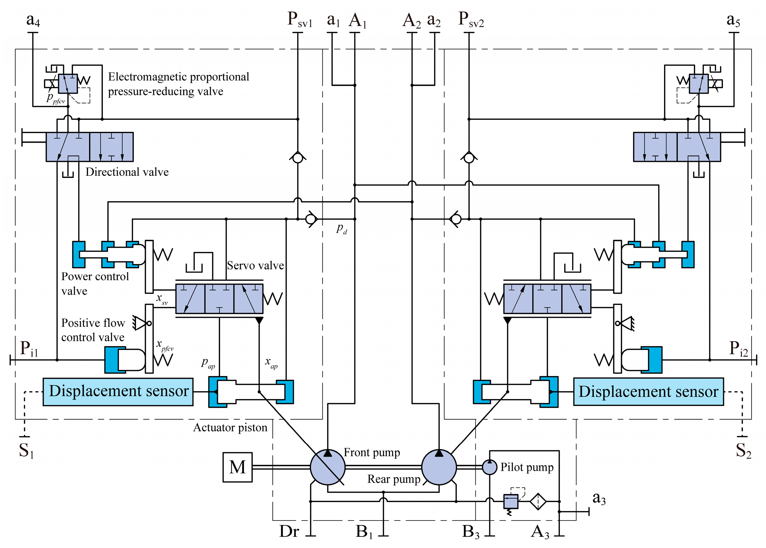
Figure 2 shows the schematic diagram of the inner-loop control system of the bi-tandem axial piston pump. The positive flow control system of the pump is composed of a pilot pump, an electromagnetic proportional pressure-reducing valve, a positive flow control valve, a control connecting rod, a servo valve, a feedback fork, and an actuator piston. In addition, the pump is equipped with a power control valve as a redundant backup for the positive flow control, which can be activated via a directional valve.
Take the front pump as an example to illustrate the flow control process of the bi-tandem axial piston pump. When the output flow rate of the front pump falls below the expected value, the controller increases the control current of the electromagnetic proportional pressure-reducing valve, leading to a rise in secondary pressure. This triggers the spool of the positive flow control valve to move toward the right, driving the servo valve spool to the left through the control connecting rod. At this point, the right functional position becomes active, and the servo valve controls the large cavity of the actuator piston to drain oil. Meanwhile, the small cavity of the actuator piston remains connected to the high-pressure working oil circuit of the front pump and the pilot control oil circuit, resulting in higher hydraulic force at the end of the small cavity compared to the end of the large cavity. Consequently, the actuator piston moves to the left, causing the inclination angle of the swash plate to increase. As a result, the displacement of the front pump increases, leading to a corresponding increase in the output flow rate. At the same time as the displacement increases, the actuator piston drives the servo valve spool through the feedback fork, closing the large cavity drainage channel of the actuator piston, thereby completing the regulation process. Conversely, when the output flow rate of the front pump exceeds the expected value, the controller lowers the control current of the electromagnetic valve, leading to a reduction in secondary pressure. This prompts the positive flow control valve spool to shift toward the left, driving the servo valve spool to the right. Consequently, the servo valve controls the high-pressure oil circuit connected to the large cavity of the actuator piston. As the hydraulic force at the end of the large cavity surpasses the small cavity, the actuator piston moves to the right, leading to a reduction in the inclination angle of the swash plate and, consequently, a decline in the displacement of the front pump. This results in an immediate decrease in the output flow rate.
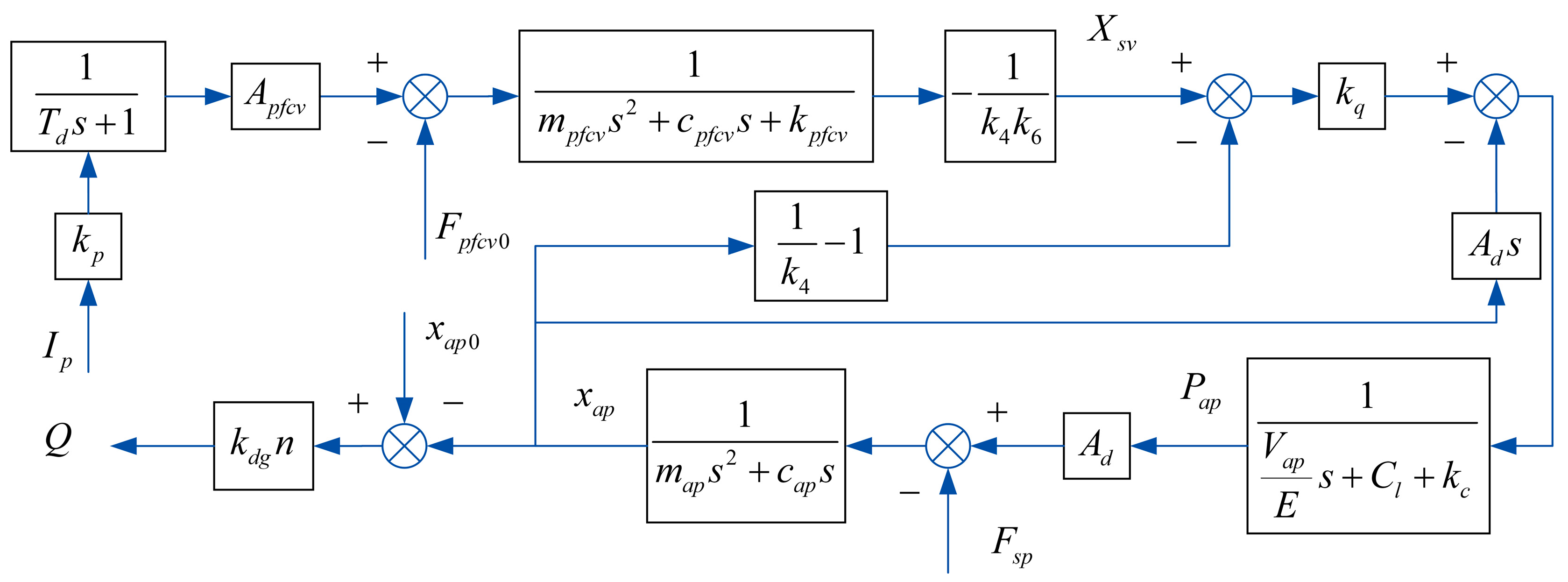
Based on its working principle, a mathematical model is established for the inner-loop control system of the pump. The pressure output equation of the electromagnetic proportional pressure-reducing valve after adjustment is:
p p f c v = k p i p i c T d d p p f c v d t
where ppfcv is the secondary pressure of the electromagnetic proportional pressure-reducing valve, kp is the proportional gain of the electromagnetic proportional pressure-reducing valve, ip is the input current, ic is the current in the proportional electromagnet, and Td is the time constant.
The motion equation of the positive flow control valve is:
p p f c v A p f c v F p f c v 0 = m p f c v x ¨ p f c v + c p f c v x ˙ p f c v + k p f c v x p f c v
where Apfcv is the effective area of the secondary pressure of the electromagnetic proportional pressure-reducing valve on the spool of the positive flow control valve, Fpfcv0 is the spring preload of the positive flow control valve, mpfcv is the mass of the positive flow control valve spool, cpfcv is the viscous damping coefficient of the positive flow control valve, xpfcv is the displacement of the positive flow control valve spool, and kpfcv is the spring stiffness of the positive flow control valve.
The relationship between the displacement of the servo valve and the displacement of the actuator piston is:
x s v = x p f c v / k 4 k 6 1 / k 4 + 1 x a p
where xsv is the displacement of the servo valve, k4 is the proportional coefficient of the position of the feedback fork, k6 is the proportional coefficient of the position of the positive flow control connecting rod, and xap is the displacement of the actuator piston.
The linearized flow equation of the servo valve is:
q s v = k q x s v k c p a p
k q = C d w s v 2 p a p / ρ
k c = C d w s v x s v 2 p a p / ρ / 2 p a p
where Cd is the flow coefficient, pap is the pressure of the actuator piston control cavity, kq is the flow gain, kc is the flow pressure coefficient, wsv is the flow area of the servo valve, and ρ is the hydraulic fluid density.
The flow continuity equation of the actuator piston control cavity is:
q s v + C l p d p a p = A d d x a p d t + V a p E d p a p d t
where Ad is the action area of the actuator piston control cavity, Cl is the internal leakage coefficient of the actuator piston, pd is the load pressure, and Vap is the volume of the actuator piston control cavity.
The motion equation of the actuator piston is:
A d p a p A x p d = m a p d 2 x a p d t 2 + c a p d x a p d t + F s p
where Ax is the action area of the large cavity of the actuator piston, map is the mass of the actuator piston, cap is the viscous damping coefficient of the actuator piston, and Fsp is the force of the swash plate on the actuator piston.
The output flow of the piston pump is:
q = k d g n x a p
k d g = π d p 2 D z 4 L s p
where kdg is the displacement gradient of the piston pump, n is the spindle speed, dp is the piston diameter, D is the diameter of the piston distribution circle, z is the number of pistons, and Lsp is the force arm of the actuator piston to the swash plate.
Based on the above mathematical model, the block diagram of the inner-loop control system of the piston pump is obtained, as shown in Figure 3.

2.3. Outer-Loop Control Model

The outer-loop control system adjusts the output signal of the system to achieve high precision and fast response by comparing the output signal with the reference input signal, as shown in Figure 4. Proportional–integral–derivative (PID) control, as an ideal control method for hydraulic systems, has the characteristics of fast response, good stability, high reliability, and small steady-state error [27]; so, most hydraulic system controllers are based on PID and its variant algorithms [28,29]. Accordingly, PID control is selected as the outer-loop control algorithm to improve the control accuracy and response speed.
The positional PID control algorithm is formulated as:
u t = K p e t + K i 0 t e τ d τ + K d d e t d t
where u(t) is the output signal of the PID controller, e(t) is the error signal, Kp is the proportional coefficient, Ki is the integral coefficient, and Kd is the differential coefficient.

2.4. Simulation Model and Experimental Verification

According to the inner-loop control model and the outer-loop control model mentioned above, the simulation model of the bi-tandem axial piston pump with dual-loop positive flow control is established based on Simulink, as shown in Figure 5. Notably, the model also includes a simulation of the bi-tandem axial piston pump with single-ring control. The specifications of the main pump and the pilot pump of the bi-tandem axial piston pump are shown in Table 1.
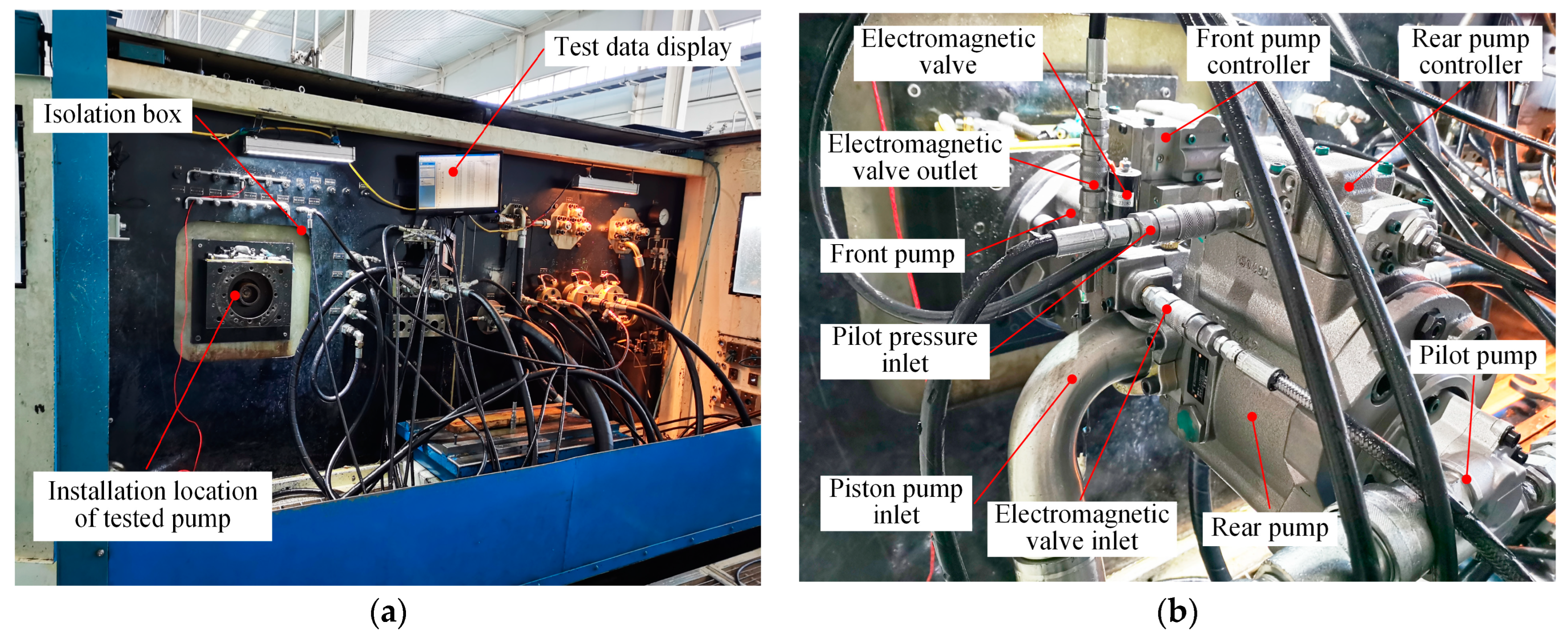
The feasibility of the simulation model is verified by taking the bi-tandem axial piston pump as the test object. The output characteristics of the simulation model of the pump with sing-loop control are verified by the test system of the bi-tandem axial piston pump, as shown in Figure 6. The previous study [22] gave the system circuit of the test system and the technical characteristics of the test sensors. The main pump (i.e., front pump or rear pump) of the bi-tandem axial piston pump is identical in structural parameters. To fully test the output characteristics of the main pump of the bi-tandem axial piston pump, it was operated without a load, and the spindle speed is set at 2000 rpm. The control current of 0~810 mA is input into the electromagnetic proportional pressure-reducing valve to test the output characteristics of the front pump. Furthermore, the control current of 0~980 mA is input into the electromagnetic proportional pressure-reducing valve, and the output characteristics of the electromagnetic proportional pressure-reducing valve are tested.
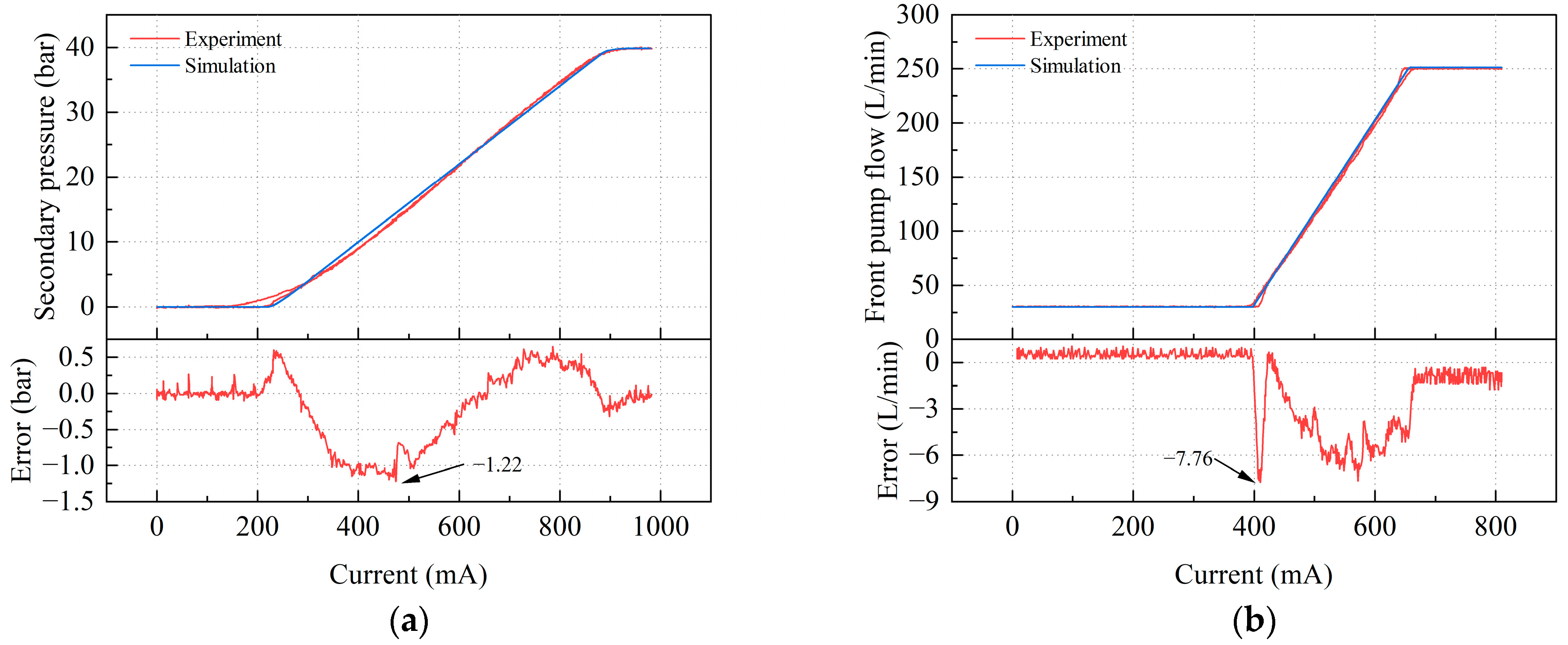
Figure 7 shows the test and simulation results of the output characteristics of the electromagnetic proportional pressure-reducing valve and the main pump of the bi-tandem axial piston pump. The secondary pressure test of the electromagnetic proportional pressure-reducing valve shows the same trend as the simulation, and the test results fluctuate near the simulation results. However, there is still a certain deviation. The maximum deviation of the secondary pressure is only −1.22 bar, so the high degree of similarity between the test and simulation results underscores the accuracy of the simulation model. Similarly, the output flow test results of the main pump demonstrated good agreement with the simulation results, albeit with some minor deviations. The maximum deviation of the output flow rate is −7.76 L/min, which occurs at the flow rate starting point, and the range is narrow, so the deviation is acceptable.
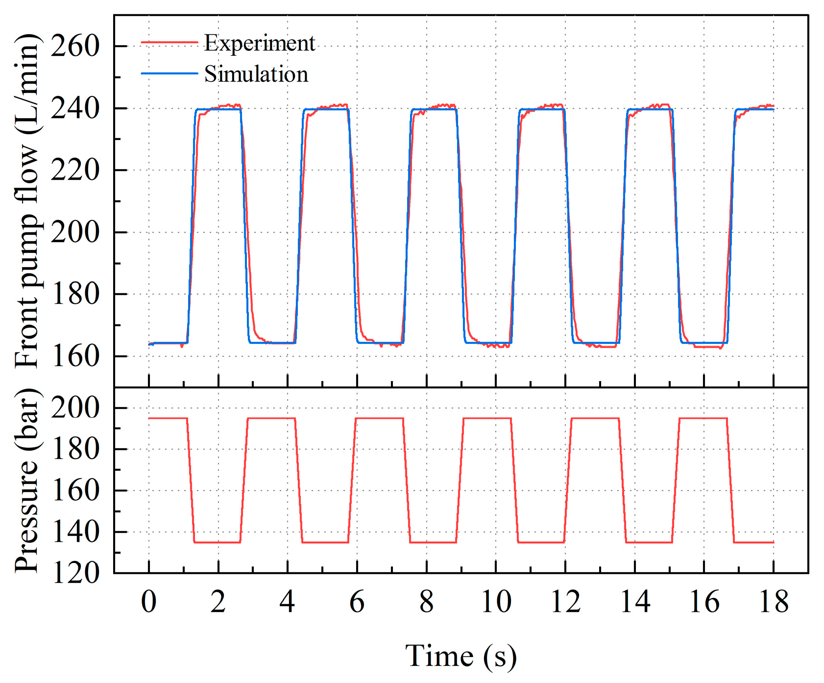
Figure 8 depicts the dynamic response of the flow rate under pressure disturbance, with test and simulation results compared. A periodic pressure disturbance of low pressure 135 bar and high pressure 195 bar is applied to both the front and rear pumps at a period of 3.11 s. Due to power restrictions and sensitivity to pressure changes, the output flow rate of the piston pump exhibited periodic fluctuations in response to the pressure disturbance. After the pressure disturbance, the output flow rate is adjusted within a short time and stabilizes with good repeatability. While the flow response time is slightly greater in the test results compared to the simulation results, the deviation was still considered acceptable given the overall strength of the predictive capabilities of the model.
Upon a careful comparison of the test and simulation results for both the secondary pressure of the electromagnetic proportional pressure-reducing valve and the output flow of the main pump, it can be observed that the test and simulation data show the same trends and a high degree of agreement, with errors well within acceptable limits. Furthermore, the test and simulation results for the dynamic response of the flow under pressure disturbance also exhibited strong agreement. Taken together, these findings provide compelling evidence that the established model of the bi-tandem axial piston pump is accurate and effective for the analysis of output characteristics and dynamic response.

3. Comparative Analysis of the Dynamic Response of the Piston Pump with Single-Loop and Dual-Loop Positive Flow Control Results

In the case of no pressure disturbance and pressure disturbance, the dynamic response of the piston pump with single-loop positive flow control and dual-loop positive flow control is compared and analyzed by a simulation. The initial flow is the maximum flow, the pressure disturbance is 343 bar, and the disturbance time point is 0.15 s.
Figure 9 shows the comparison of the dynamic response of the piston pump with single-loop and dual-loop positive flow control under no pressure disturbance and pressure disturbance. With no pressure disturbance, the adjustment time for the single-loop control is 0.10 s, with a steady-state relative error of −1.52 × 10⁻³. This compares to 0.04 s for the dual-loop control, with a steady-state relative error of −7.85 × 10⁻⁴. Under the pressure disturbance, the adjustment time for the single-loop control is 0.125 s, and the steady-state relative error is 1.37 × 10⁻². The adjustment time of the dual-loop control is 0.05 s, and the steady-state relative error is 3.58 × 10⁻³. The feedback loop of the single-loop control is realized by the mechanical connecting rod, and the double-loop control adds the output feedback link on the basis of the single-loop control. As a result, single-loop control is limited in its implementation of advanced control strategies, whereas dual-loop control uses a PID controller to optimize the response characteristics. The dual-loop control, therefore, has a superior response speed compared to the single-loop control. Therefore, the bi-tandem axial piston pump with the dual-loop positive flow control has superior dynamic characteristics compared to the single-loop control. Regardless of whether there is pressure disturbance, the response speed is faster, and the steady-state error is smaller. The pressure disturbance increases the steady-state error.

4. Dynamic Response Analysis of the Bi-Tandem Axial Piston Pump under Pressure Disturbance

In the operating condition, the bi-tandem axial piston pump with positive flow control is limited by the input power to prevent the occurrence of overload conditions, so the piston pump is sensitive to the load near the power wall. When subjected to significant load pressure disturbance, the output flow of the piston pump is susceptible to experiencing disruption. Therefore, the output flow response characteristics of the piston pump under pressure disturbance have a great influence on the operating process of double pumps.
The double pumps can be divided into cooperative oil supply and independent oil supply according to the liquid supply requirements of the actuator. In the case of collaborative oil supply, two main pumps work together to provide a high-pressure power medium for the same actuator. While in the case of independent supply, two main pumps provide a high-pressure power medium for two or more actuators. Therefore, it is subjected to symmetric pressure disturbance during cooperative oil supply and is subjected to asymmetric pressure disturbance during independent oil supply. This section is primarily concerned with the implications of pressure disturbance in terms of its form, degree, and direction on the dynamic response of the bi-tandem axial piston pump through simulation.

4.1. Effect of Symmetric Pressure Disturbance on Dynamic Response

When double pumps cooperate to supply oil, the output flow is the same and the load pressure is the same, so the pressure disturbance is also the same, which is called symmetric pressure disturbance.

4.1.1. Degree of Symmetric Pressure Disturbance

The initial displacement of the front pump and the rear pump is set to the maximum displacement, the initial load pressure is set to 0 bar, the pressure disturbance time point is 0.15 s, the degree of pressure disturbance is set to 100 bar, 200 bar, 300 bar, and 343 bar, respectively, and the total output power is limited to 107 kW. The effect of different degrees of symmetric pressure disturbance on the dynamic response of the bi-tandem axial piston pump is analyzed.
Because the working states of the double pumps are the same, the output characteristics of the double pumps are the same. The dynamic response of the bi-tandem axial piston pump under different degrees of symmetric pressure disturbance is shown in Figure 10. The main pump reaches the initial set flow from the minimum flow within 0.05 s, and the steady-state error is 0. Before the pressure disturbance, the main pump operates at the set flow rate. The piston pump is subjected to symmetric pressure disturbance at 0.15 s, and the output flow of the main pump is not affected under the pressure disturbance of 100 bar, while the output flow of the main pump decreases rapidly and reaches a stable state rapidly under the pressure disturbance of 200 bar. This is because the bi-tandem axial piston pump is limited by the power wall when it is working. When the pressure disturbance is greater than the starting pressure, the output flow rate of the main pump reduces accordingly to avoid the overload of the piston pump. The output flow of the main pump shows a decreasing trend with an increase in the degree of symmetric pressure disturbance. The maximum relative error in output flow rate is 0.56, 1.35, and 1.68 for symmetric pressure disturbances at 200 bar, 300 bar, and 343 bar, respectively. The maximum relative error appears at the time point of symmetric pressure disturbance, and the maximum relative error increases with the increase in symmetric pressure disturbance. It can be seen that the adjustment time increases with the increase in the degree of symmetric pressure disturbance, but the adjustment time is still small. The bi-tandem axial piston pump with dual-loop positive flow control still maintains a good fast response under the condition of large symmetric pressure disturbance.

4.1.2. Direction of Symmetric Pressure Disturbance

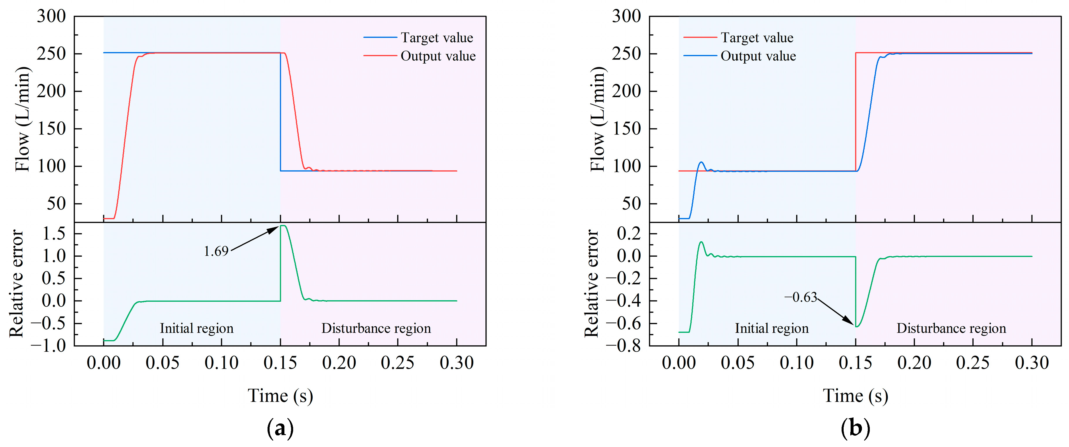
The initial displacement of the front pump and the rear pump is set to the maximum displacement, and the pressure disturbance time point is 0.15 s. When loading pressure disturbance, the initial load pressure is set to 0 bar and the loading pressure disturbance is set to 343 bar. When unloading pressure disturbance, the initial load pressure is set to 343 bar and the unloading pressure disturbance is set to 0 bar. The effect of symmetric pressure disturbance in different directions on the dynamic response of the bi-tandem axial piston pump is analyzed.
The dynamic response of the bi-tandem axial piston pump under symmetric pressure disturbance in different directions is shown in Figure 11. In the initial region, the rise time of the piston pump is small at a larger initial load pressure, but the output flow oscillates. The steady-state value of the output flow of the main pump is the same after the effect of the loading pressure disturbance and before the effect of the unloading pressure disturbance. Under the disturbance of loading pressure, the output flow value decreases correspondingly, and the oscillation occurs before reaching stability. Under the disturbance of unloading pressure, the output flow value increases correspondingly, and the oscillation is not obvious before reaching the steady-state value. Under the loading pressure disturbance, the maximum relative error of the output flow is 1.69. Under the unloading pressure disturbance, the maximum relative error of the output flow is −0.63. Therefore, the unloading pressure disturbance has less impact on the system than the loading pressure disturbance.

4.2. Effect of Asymmetric Pressure Disturbance oTan Dynamic Response

When the double pumps supply oil independently, they carry different actuator loads. Although the output flow is the same, the pressure disturbance is different in degree and direction, which is called asymmetric pressure disturbance.

4.2.1. Degree of Asymmetric Pressure Disturbance

The initial displacement of the front pump and the rear pump is set to the maximum displacement, the initial load pressure is set to 0 bar, the pressure disturbance time point of the front pump is 0.1 s (the first disturbance point), and the pressure disturbance time point of the rear pump is 0.2 s (the second disturbance point). Different degrees of asymmetric pressure disturbance are selected for double pumps, as shown in Table 2, to analyze the effect of different degrees of asymmetric pressure disturbance on the dynamic response of the bi-tandem axial piston pump.
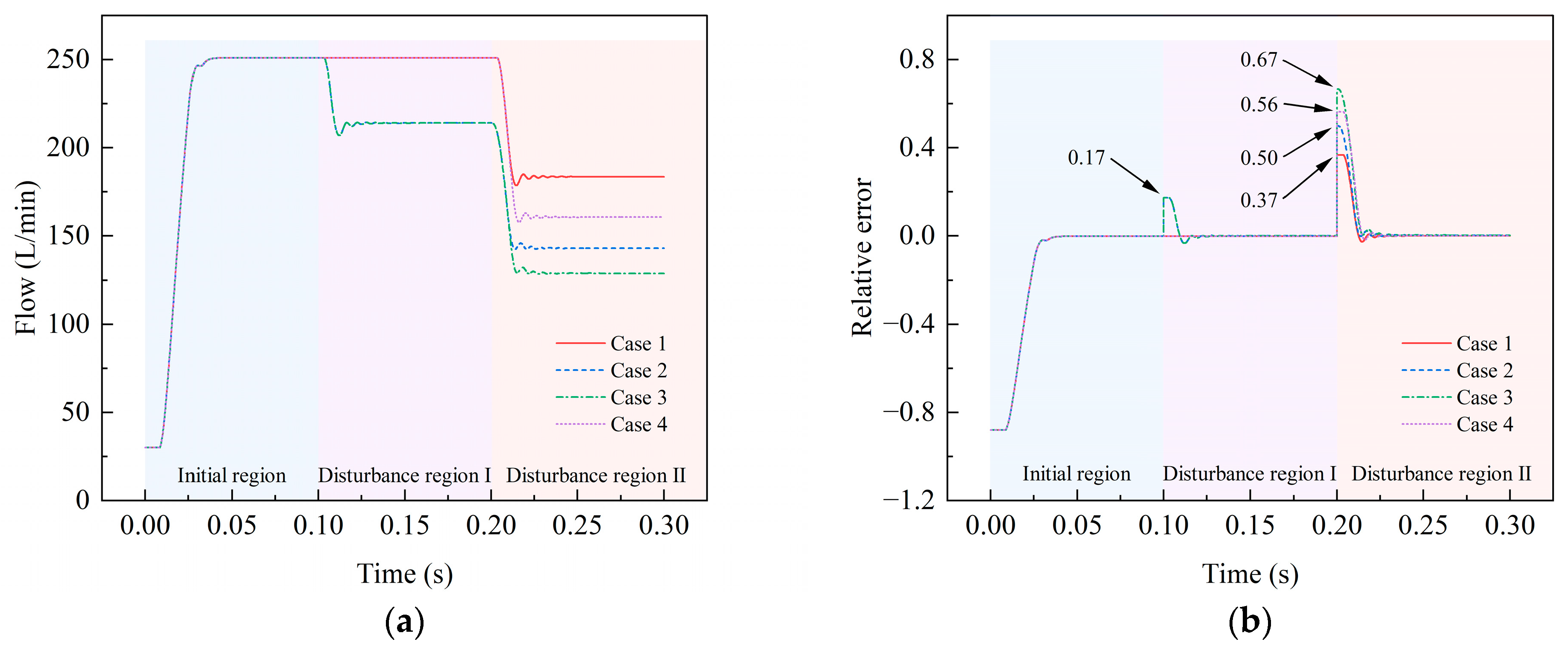
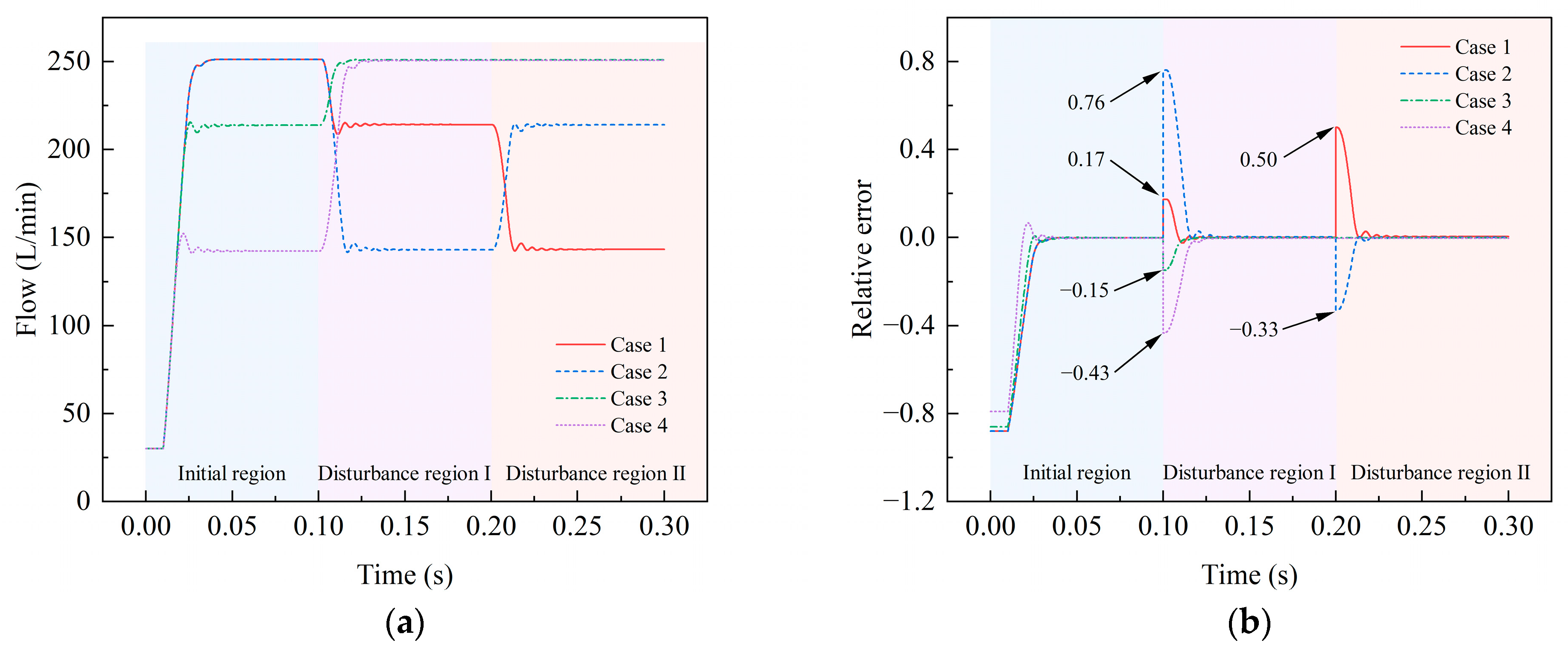
Figure 12 shows the dynamic response of the bi-tandem axial piston pump under different degrees of asymmetric pressure disturbance. Under the asymmetric pressure disturbance in cases 1 and 4, at the first disturbance point, only the front pump is disturbed by pressure, and the output flow of the main pump is not affected. At the second disturbance point, the main pump output flow decreases rapidly and tends to be stable after a short oscillation. It can be seen that the steady-state value decreases with the increase in pressure disturbance, and the adjustment time increases slightly with the increase in pressure disturbance. Under the asymmetric pressure disturbance of cases 2 and 3, at the first disturbance point, the pressure disturbance of 300 bar in the front pump causes the main pump’s output flow to be readjusted. At the second disturbance point, the output flow of the main pump decreases again due to the pressure disturbance of the rear pump, and the steady-state value decreases with the increase in the pressure disturbance degree of the rear pump, while the adjustment time increases slightly with the increase in the pressure disturbance degree of the rear pump.
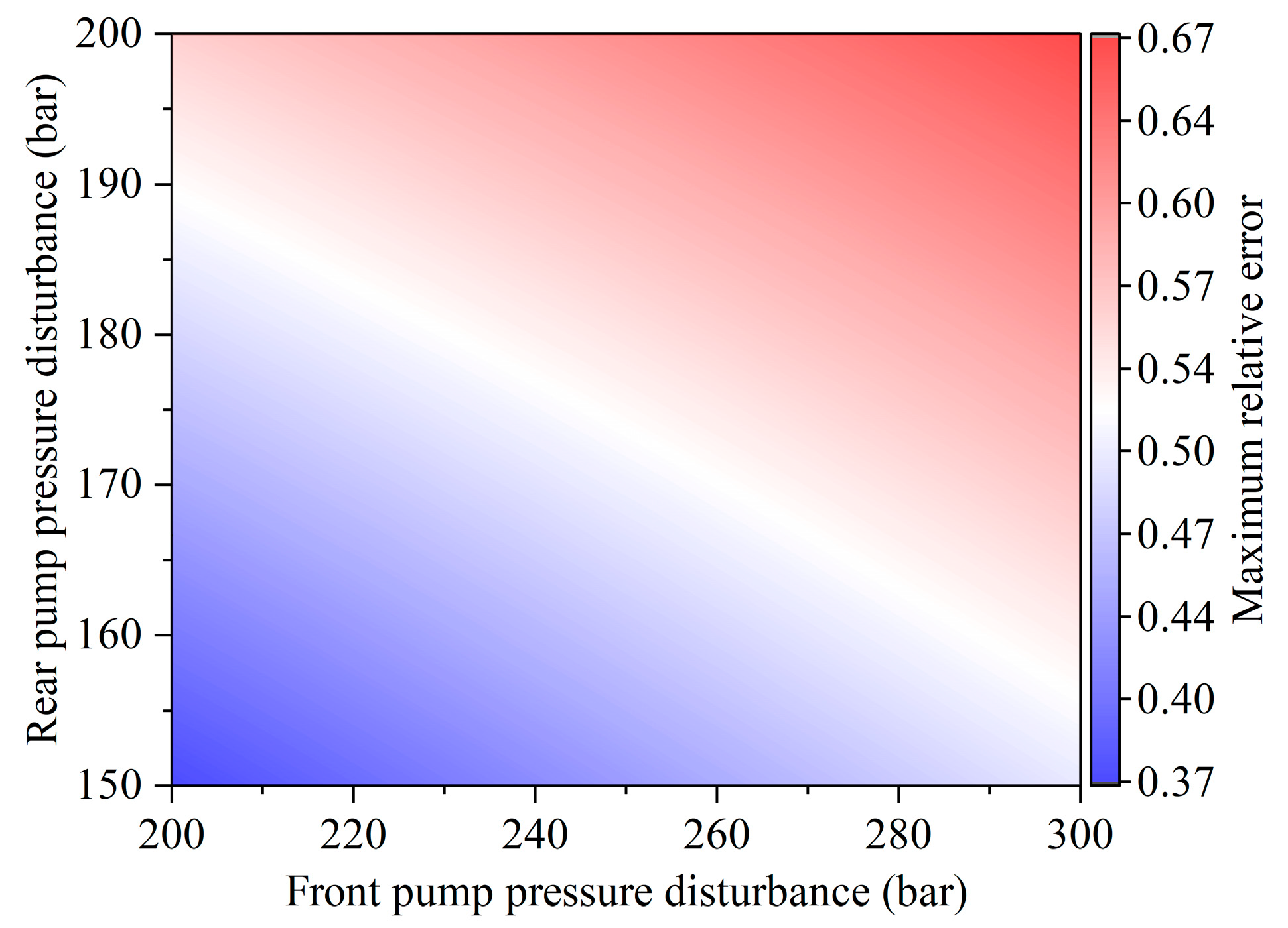
Because the output flow of the main pump is adjusted twice under cases 2 and 3, the relative error fluctuates twice at the first and second pressure disturbance points, respectively. The maximum relative error is 0.50 under the pressure disturbance of the rear pump at 150 bar and 0.67 under the pressure disturbance of the rear pump at 200 bar. Under cases 1 and 4, the output flow of the main pump is adjusted once, and the maximum relative error is 0.37 under the pressure disturbance of the rear pump at 150 bar and 0.56 under the pressure disturbance of the rear pump at 200 bar. The maximum relative error at the second disturbance point increases with the increase in the pressure disturbance degree of the rear pump under the same pressure disturbance of the front pump, as shown in Figure 13. For the same pressure disturbance of the rear pump, the maximum relative error at the second disturbance point increases with the increase in the pressure disturbance degree of the front pump, and this law is not affected by whether the piston pump adjusts the output under the pressure disturbance of the rear pump.

4.2.2. Direction of Asymmetric Pressure Disturbance

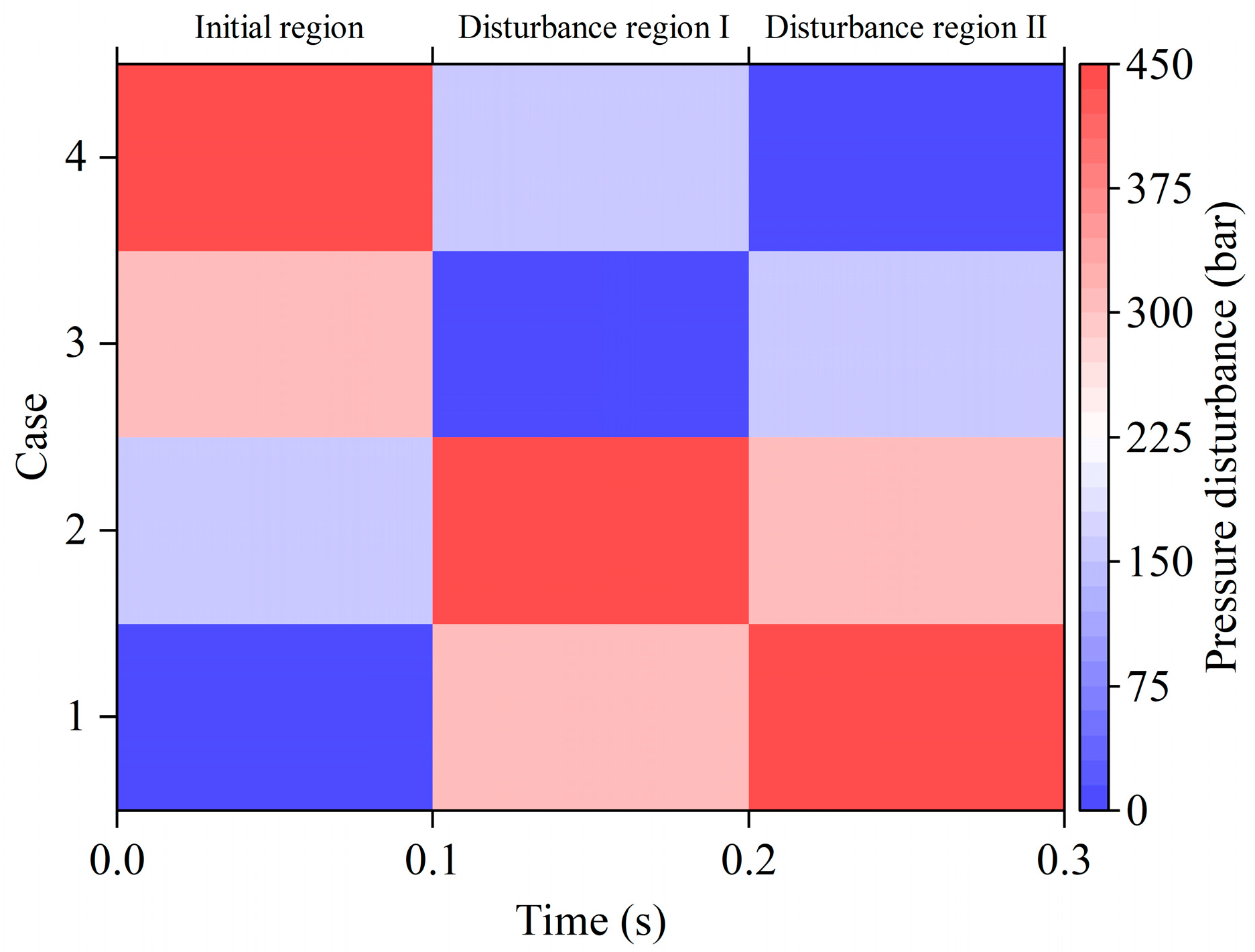
The initial displacement of the front pump and the rear pump is set to the maximum displacement. The front pump has a loading pressure disturbance of 300 bar, an unloading pressure disturbance of 0 bar, and a pressure disturbance time point of 0.1 s. The rear pump has a loading pressure disturbance of 150 bar, an unloading pressure disturbance of 0 bar, and a pressure disturbance time point of 0.2 s. There are four cases according to the different directions of the pressure disturbance of the front pump and the rear pump, as shown in Table 3. The effect of asymmetric pressure disturbance in different directions on the dynamic response of the bi-tandem axial piston pump is analyzed.
In each case, the front pump and the rear pump are successively subjected to pressure disturbance, and the main pump adjusts their output flow twice in the disturbance region I and the disturbance region II. The mathematical sum of the pressure disturbance of the front and rear pumps at the same time is defined as the superimposed pressure disturbance. The superimposed pressure disturbance in each region under each case is shown in Figure 14. Figure 15 shows the dynamic response of the bi-tandem axial piston pump under asymmetric pressure disturbance in different directions. The output flow rate of the main pump is the same for the same superimposed pressure disturbance in each region. It can be concluded that the effect of the asymmetric pressure disturbance of double pumps on the output flow has a superposition property. The steady-state value of the output flow is strongly related to the superimposed pressure disturbance and is less affected by the action time point of the asymmetric pressure disturbance.
In the initial region, the greater the superimposed pressure disturbance, the greater the output flow overshoot. In each disturbance region, the output flow oscillation is the weakest when disturbed by full unloading pressure. The pattern of the smaller maximum relative error caused by unloading pressure disturbance relative to loading pressure disturbance is still demonstrated in each disturbance region, as shown in Figure 15b.

5. Conclusions

In this paper, a dual-loop positive flow control method is proposed for the bi-tandem axial piston pump to enhance the response characteristics of the bi-tandem axial piston pump with positive flow control. To this end, the model of the bi-tandem axial piston pump with dual-loop positive flow control is developed, and the validity of the model is verified by experiments. The response characteristics of the bi-tandem axial piston pump under single-loop and dual-loop positive flow control are analyzed in simulation, and the impact of various factors, such as the form, degree, and direction of pressure disturbance on the dynamic response characteristics of the bi-tandem axial piston pump, is thoroughly analyzed. The results are as follows:
(1)
In response to the problem that the stability of the original single-loop mechanical–hydraulic servo control system is susceptible to uncertain interferences, a dual-loop positive flow control method is developed for the bi-tandem axial piston pump. Based on Simulink, the simulation model of the bi-tandem axial piston pump with dual-loop positive flow control is established. The model is verified to be accurate and reliable through experiments.
(2)
Compared with the single-loop positive flow control, the axial piston pump with dual-loop positive flow control has faster response speed and smaller steady-state error under no pressure disturbance and pressure disturbance.
(3)
Under symmetric pressure disturbance, the output characteristics of double pumps are identical. When the pressure disturbance exceeds the starting pressure, the output flow of the piston pump declines sharply, with stability eventually reached after a brief period of oscillation. Notably, the corresponding adjustment time increases with the increase in the degree of symmetrical pressure disturbance. Furthermore, the maximum relative error in output flow at the action point of the symmetric pressure disturbance increases with the increase in symmetrical pressure disturbance. It is worth noting that unloading pressure disturbances elicit less pronounced effects on the system compared to loading pressure disturbances.
(4)
In the presence of asymmetric pressure disturbance, the maximum relative error at the second disturbance point increases with the increase in pressure disturbance of the rear pump for the same pressure disturbance of the front pump. Similarly, the maximum relative error at the second disturbance point increases with the increase in the pressure disturbance of the front pump for the same pressure disturbance of the rear pump, and this pattern remains consistent, regardless of whether the piston pump adjusts its output under the pressure disturbance of the rear pump. The effect of asymmetric pressure disturbance of double pumps on output flow is of a superimposable nature, with the steady-state value of the output flow strongly influenced by the superimposed pressure disturbance while displaying lesser sensitivity to the action time points of asymmetric pressure disturbance. Furthermore, across all disturbance regions, the maximum relative error caused by unloading pressure disturbance is smaller than that caused by loading pressure disturbance.
By precisely controlling the operating state of the piston pump, the efficiency and performance of the piston pump can be effectively improved, thereby reducing energy consumption while maintaining optimal load balance. Secondly, the dynamically improved control strategy can adapt to different working condition requirements, providing the basis for intelligent control and adaptive adjustment of the pump, thus improving the reliability and stability of the system.
There are still some shortcomings in this work; the potential impact of the swash plate vibration on the system response during the operation of the piston pump has not been considered. Therefore, the inclusion of swash plate dynamics in the model needs to be completed in further work. Furthermore, in further work, additional experimental testing of the described system is required to fully analyze the dynamic response under different pressure perturbations. To realize the precise control of the actual output of the piston pump, a future study will add the flow leakage compensation method to the control method.

Author Contributions

Conceptualization, Z.S.; methodology, Z.S.; software, Z.S.; validation, Z.S., Q.Z. and L.W.; formal analysis, Z.S.; investigation, Z.S. and L.W.; Resources, Y.X.; data curation, Z.S.; writing—original draft preparation, Z.S.; writing—review and editing, Q.Z. and Z.S.; visualization, Z.S.; supervision, Q.Z.; project administration, L.W.; funding acquisition, Q.Z. and L.W. All authors have read and agreed to the published version of the manuscript.

Funding

This research was funded by the National Natural Science Foundation of China (grant numbers 51974170 and 52274132) and the Shandong Province Key Research and Development Program (grant number 2019SDZY01).

Institutional Review Board Statement

Not applicable.

Informed Consent Statement

Not applicable.

Data Availability Statement

The data used to support the findings of this study are included within the article.

Acknowledgments

The authors would like to thank engineer Xiao Ying for his technical support in this work.

Conflicts of Interest

The authors declare no conflict of interest.

References

  1. Wang, L.K.; Book, W.J.; Huggins, J.D. Application of Singular Perturbation Theory to Hydraulic Pump Controlled Systems. IEEE-ASME Trans. Mechatron. 2012, 17, 251–259. [Google Scholar] [CrossRef]
  2. Lu, L.; Chen, Y.; Tong, C.; Ruan, J.; Li, S. Design strategy and performance evaluation of novel miniature two-dimensional (2D) piston pump with a dual stacking mechanism. Alex. Eng. J. 2023, 62, 541–554. [Google Scholar] [CrossRef]
  3. Zhao, J.A.; Fu, Y.L.; Ma, J.M.; Fu, J.; Chao, Q.; Wang, Y. Review of cylinder block/valve plate interface in axial piston pumps: Theoretical models, experimental investigations, and optimal design. Chin. J. Aeronaut. 2021, 34, 111–134. [Google Scholar] [CrossRef]
  4. Manring, N.; Williamson, C.; Asme. Calculating the Mechanical and Volumetric Efficiencies for Check-Valve Type, Digital Displacement Pumps. In Proceedings of the BATH/ASME Symposium on Fluid Power and Motion Control, University of Bath, Bath, UK, 12–14 September 2018; pp. 1–10. [Google Scholar]
  5. De Negri, V.J.; Wang, P.; Plummer, A.; Johnston, D.N. Behavioural prediction of hydraulic step-up switching converters. Int. J. Fluid Power 2014, 15, 1–9. [Google Scholar] [CrossRef]
  6. Kogler, H. High dynamic digital control for a hydraulic cylinder drive. Proc. Inst. Mech. Eng. Part I-J. Syst. Control Eng. 2022, 236, 382–394. [Google Scholar] [CrossRef]
  7. Tang, H.B.; Yang, W.X.; Wang, Z.C. A Model-Based Method for Leakage Detection of Piston Pump Under Variable Load Condition. IEEE Access 2019, 7, 99771–99781. [Google Scholar] [CrossRef]
  8. Ying, P.; Tang, H.; Chen, L.; Ren, Y.; Kumar, A. Dynamic modeling and vibration characteristics of multibody system in axial piston pump. Alex. Eng. J. 2023, 62, 523–540. [Google Scholar] [CrossRef]
  9. Ivantysynova, M.; Grabbel, J.; Ossyra, J.-C. Prediction of swash plate moment using the simulation tool CASPAR. In Proceedings of the ASME 2002 International Mechanical Engineering Congress and Exposition, IMECE 2002, New Orleans, LA, USA, 17–22 November 2002; pp. 1–9. [Google Scholar]
  10. Grabbel, J.; Ivantysynova, M. An investigation of swash plate control concepts for displacement controlled actuators. Int. J. Fluid Power 2005, 6, 19–36. [Google Scholar] [CrossRef]
  11. Bergada, J.M.; Watton, J.; Kumar, S. Pressure, flow, force, and torque between the barrel and port plate in an axial piston pump. J. Dyn. Sys. Meas. Control. 2008, 130, 16. [Google Scholar] [CrossRef]
  12. Cui, H.-X.; Feng, K.; Li, H.-L.; Han, J.-H. Response Characteristics Analysis and Optimization Design of Load Sensing Variable Pump. Math. Probl. Eng. 2016, 2016, 6379121. [Google Scholar] [CrossRef] [Green Version]
  13. Du, C.; Plummer, A.R.; Johnston, D.N. Performance analysis of a new energy-efficient variable supply pressure electro-hydraulic motion control method. Control Eng. Pract. 2017, 60, 87–98. [Google Scholar] [CrossRef]
  14. Gao, Y.S.; Cheng, J.; Huang, J.H.; Quan, L. Simulation Analysis and Experiment of Variable-Displacement Asymmetric Axial Piston Pump. Appl. Sci. 2017, 7, 328. [Google Scholar] [CrossRef] [Green Version]
  15. Hasan, M.E.; Ghoshal, S.K.; Dasgupta, K.; Kumar, N. Dynamic analysis and estimator design of a hydraulic drive system. J. Braz. Soc. Mech. Sci. Eng. 2017, 39, 1097–1108. [Google Scholar] [CrossRef]
  16. Li, J.; Li, H.L.; Cui, H.X.; Zhu, Y.W. Nonlinear dynamics characteristics and influence factors analysis of servo hydraulic cylinder. Proc. Inst. Mech. Eng. Part C-J. Eng. Mech. Eng. Sci. 2018, 232, 3629–3638. [Google Scholar] [CrossRef]
  17. Huang, J.H.; Zhao, H.; Quan, L.; Zhang, X.G. Development of an asymmetric axial piston pump for displacement-controlled system. Proc. Inst. Mech. Eng. Part C-J. Eng. Mech. Eng. Sci. 2014, 228, 1418–1430. [Google Scholar] [CrossRef]
  18. Huang, J.; He, W.; Hao, H.; Quan, L. Analysis of Control Characteristics of Variable-displacement Asymmetric Axial Piston Pump. Trans. Chin. Soc. Agric. Mach. 2019, 50, 368–376. [Google Scholar] [CrossRef]
  19. He, W.; Huang, J.H.; Hao, H.M.; Quan, L.; Ji, S.X.; Zhao, B. Design and Analysis of a Swashplate Control System for an Asymmetric Axial Piston Pump. J. Dyn. Syst. Meas. Control-Trans. ASME 2020, 142, 11. [Google Scholar] [CrossRef]
  20. Mitov, A.; Kralev, J.; Slavov, T.; Angelov, I. Design of Embedded Control System for Open Circuit Axial Piston Pump. In Proceedings of the 22nd International Symposium on Electrical Apparatus and Technologies, SIELA 2022, Bourgas, Bulgaria, 1–4 June 2022; pp. 1–4. [Google Scholar]
  21. Mitov, A.; Slavov, T.; Kralev, J. Rapid Prototyping of H∞ Algorithm for Real-Time Displacement Volume Control of Axial Piston Pumps. Algorithms 2023, 16, 120. [Google Scholar] [CrossRef]
  22. Sun, Z.Y.; Zeng, Q.L.; Wan, L.R.; Dai, H.Z. Control and Dynamic Characteristics Analysis for the Double-Compound Axial Piston Pump Based on Working Conditions. Machines 2022, 10, 411. [Google Scholar] [CrossRef]
  23. Li, Y.; Chen, X.; Luo, H.; Zhang, J. An Empirical Model for the Churning Losses Prediction of Fluid Flow Analysis in Axial Piston Pumps. Micromachines 2021, 12, 398. [Google Scholar] [CrossRef]
  24. Zhao, K.P.; He, T.; Wang, C.L.; Chen, Q.M.; Li, Z.P. Lubrication characteristics analysis of slipper pair of digital valve distribution axial piston pump. Adv. Mech. Eng. 2022, 14, 1–15. [Google Scholar] [CrossRef]
  25. Chao, Q.; Xu, Z.; Tao, J.; Liu, C. Capped piston: A promising design to reduce compressibility effects, pressure ripple and cavitation for high-speed and high-pressure axial piston pumps. Alex. Eng. J. 2023, 62, 509–521. [Google Scholar] [CrossRef]
  26. Kim, H.; Cheon, D.; Lim, J.; Nam, K. Robust Flow Control of a Syringe Pump Based on Dual-Loop Disturbance Observers. IEEE Access 2019, 7, 135427–135438. [Google Scholar] [CrossRef]
  27. Wang, H.; Wang, X.H.; Huang, J.H.; Quan, L. Flow Control for a Two-Stage Proportional Valve with Hydraulic Position Feedback. Chin. J. Mech. Eng. 2020, 33, 13. [Google Scholar] [CrossRef]
  28. Li, Y.; Ang, K.H.; Chong, G.C.Y. Patents, software, and hardware for PID control: An overview and analysis of the current art. IEEE Control Syst. Mag. 2006, 26, 42–54. [Google Scholar] [CrossRef] [Green Version]
  29. Ang, K.H.; Chong, G.; Li, Y. PID control system analysis, design, and technology. IEEE Trans. Control Syst. Technol. 2005, 13, 559–576. [Google Scholar] [CrossRef] [Green Version]
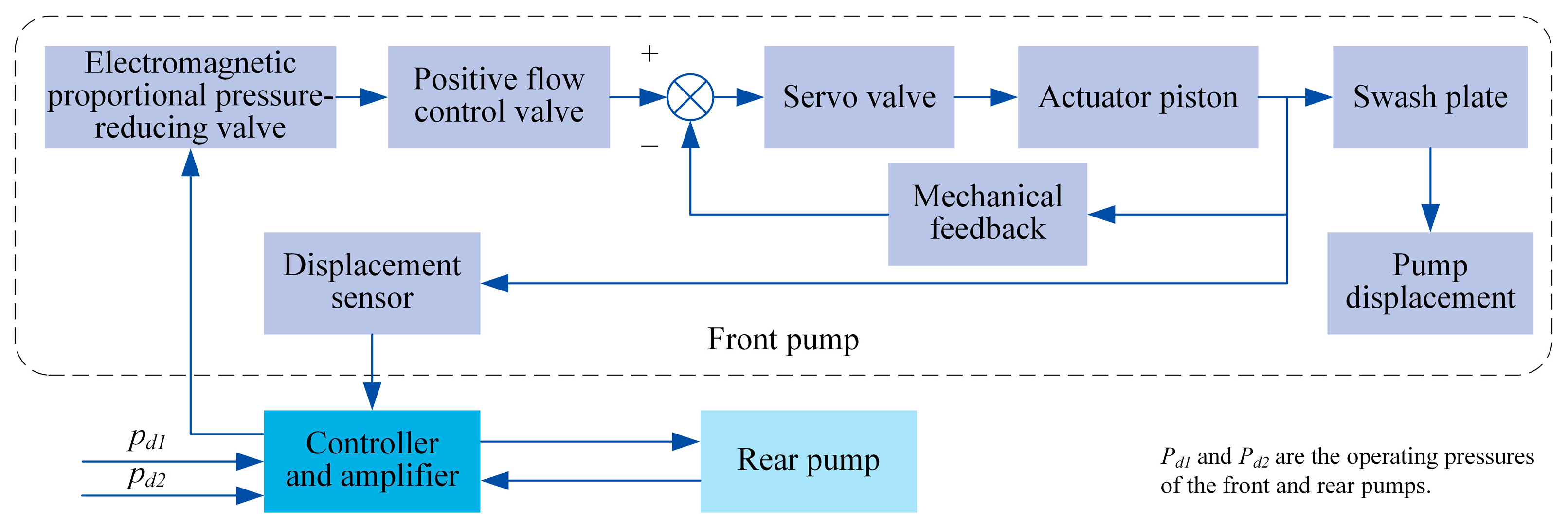
Figure 1. System block diagram of the bi-tandem axial piston pump with the dual-loop positive flow control.
Actuators 12 00260 g001
Figure 2. Schematic diagram of the inner-loop control system of the bi-tandem axial piston pump.
Actuators 12 00260 g002
Figure 3. Block diagram of the inner-loop control system.
Actuators 12 00260 g003
Figure 4. Block diagram of the outer-loop control system.
Actuators 12 00260 g004
Figure 5. Simulation model of the bi-tandem axial piston pump with dual-loop positive flow control.
Actuators 12 00260 g005
Figure 6. Test system for the bi-tandem axial piston pump: (a) test bench; (b) tested pump.
Actuators 12 00260 g006
Figure 7. Test and simulation results and their errors: (a) electromagnetic proportional pressure reducing valve; (b) main pump.
Actuators 12 00260 g007
Figure 8. Test and simulation results of the dynamic response of the piston pump flow under pressure disturbance.
Actuators 12 00260 g008
Figure 9. Comparative analysis of the dynamic response of the piston pump with single-loop and dual-loop positive flow control: (a) no pressure disturbance; (b) pressure disturbance.
Actuators 12 00260 g009
Figure 10. Dynamic response of the bi-tandem axial piston pump under different degrees of symmetric pressure disturbance: (a) flow; (b) relative error.
Actuators 12 00260 g010
Figure 11. Dynamic response of the bi-tandem axial piston pump under symmetric pressure disturbance in different directions: (a) loading pressure disturbance; (b) unloading pressure disturbance.
Actuators 12 00260 g011
Figure 12. Dynamic response of the bi-tandem axial piston pump under different degrees of asymmetric pressure disturbance: (a) flow; (b) relative error.
Actuators 12 00260 g012
Figure 13. Effect of pressure disturbance degree of the front and rear pumps on the maximum relative error at the second point of disturbance.
Actuators 12 00260 g013
Figure 14. Superposed pressure disturbance in each region for various working cases.
Actuators 12 00260 g014
Figure 15. Dynamic response of the bi-tandem axial piston pump under asymmetric pressure disturbance in different directions: (a) flow; (b) relative error.
Actuators 12 00260 g015
Table 1. Specifications for the main pump and the pilot pump of the bi-tandem axial piston pump.
PumpParameterValue
Main pumpDisplacement (cm3/rev)2 × (125 ± 2)
Speed (rpm)Rated2000
Max.2700
Pressure (bar)Rated343
Peak400
Flow (L/min)Max.2 × (251 ± 3)
Min.2 × (30 ± 3)
Pilot pumpDisplacement (cm3/rev)10
Rated pressure (bar)40 ± 1
Table 2. Different degrees of asymmetric pressure disturbance.
Case No.1234
Front pump pressure disturbance (bar)200300300200
Rear pump pressure disturbance (bar)150150200200
Table 3. Asymmetric pressure disturbances in different directions.
Case No.1234
Front pumpLoadingLoadingUnloadingUnloading
Rear pumpLoadingUnloadingLoadingUnloading
Disclaimer/Publisher’s Note: The statements, opinions and data contained in all publications are solely those of the individual author(s) and contributor(s) and not of MDPI and/or the editor(s). MDPI and/or the editor(s) disclaim responsibility for any injury to people or property resulting from any ideas, methods, instructions or products referred to in the content.