1. Introduction
Currently, composite floors are widely used in multistory commercial and office buildings due to their capability to span longer distances with stronger, stiffer, and lighter structural solutions, which are economical and offer a fast construction process. Their use often implies the reduction of the primary structure and the foundations of the building, thus reducing its overall embodied carbon (EC) [
1]. Over recent decades, the increasing use of large open-plan spaces and the rise of the electronic office has led to the reduction of dead and live loads (1 kPa less) [
2,
3] due to the removal of full-height partitions and heavy furnishing elements. As a consequence, modern composite floors have lower damping ratios (around 1% to 3% [
4,
5,
6,
7]), lower mass, and lower fundamental natural frequencies (often below 10 Hz), making them more prone to vibrate under human-induced dynamic loading, such as walking in offices or rhythmic activities in gymnasiums [
8]. Furthermore, restrictive vibration comfort levels (0.02–0.04 m/s
2) are presently required for floors in calm environments such as residences, offices, and hospitals. In this context, the Vibration Serviceability Limit State (VSLS) has become a sizing criterion to consider when designing composite floors [
9].
Excessive vibrations are often related to low-frequency floors (LFF) (with natural frequencies below 10 Hz) due to their resonance with the 2nd, 3rd, or even 4th harmonic of the human dynamic loading. In high-frequency floors (HFF) (above 10 Hz) it is considered that the vibration does not have a resonant nature and is made of consecutive transient decaying responses of the floor to each human footfall [
5]. Knowing this, structural designers often try to include stiffer-enough steel members (that raise the natural frequencies of the floor to avoid resonance) or heavy concrete slabs that decrease the amplitude of the vibration [
10]. This practice leads to a significant increase in the material used on the floor (especially relevant when the vibration limits to comply are very restrictive) affecting its lightness and increasing its EC as has been proved by Gonçalves and Pavic in [
9]. This research studies the structural oversizing to be performed in a composite floor of 30 m × 44 m with bays of 6 m × 10 m when the VSLS to be met becomes more restrictive (changing from a limiting root mean square (rms) acceleration of 0.04 m/s
2 to 0.02 m/s
2). They concluded that the floor weight should be increased by 27% and its EC by 14% to accomplish the new comfort level. Alternatively, the integration of damping strategies into the floor’s design may be an effective way of improving their dynamic performance without increasing their structural mass, thus, minimizing their EC. This is a key point considering that floors are responsible for around 70% of the total EC of the superstructure of a building [
11,
12].
Two main types of damping strategies may be used to solve floor vibration problems. First, the use of inertial dampers, in their passive versions (most known as Tuned Mass Dampers or TMDs) [
13], semi-active [
14] and active versions [
15] that apply counteract forces in real time to reduce the structural motion. Second, the use of dissipative strategies that enable increasing the inherent damping of the floor by wisely including specific elements that dissipate additional energy, such as viscous or Viscoelastic (VE) dampers. This paper studies one damping treatment related to this second group: Constrained Layer Damping (CLD). It consists of a thin VE layer embedded between two elastic bending members. The VE layer suffers shear deformation when the constraining elastic members vibrate in bending modes, hence additional energy is dissipated through a stress-strain shear hysteresis [
16].
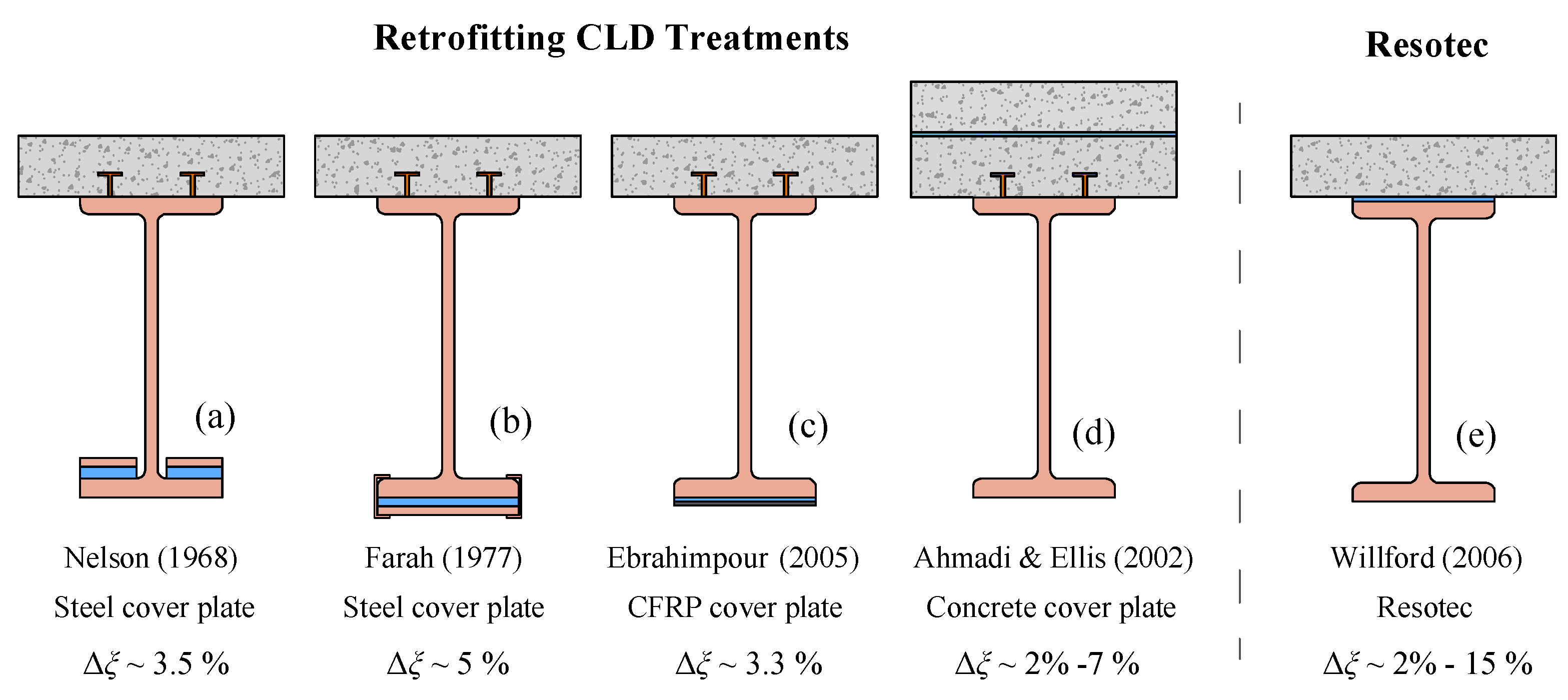
CLD treatments were developed and have been extensively applied in aerospace and mechanical engineering to mitigate broad-band frequency vibrations [
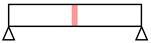
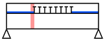
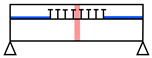
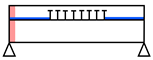
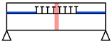
17]. Their use in civil engineering is still limited, although, some studies have been carried out using them to improve the dynamic performance of composite floors. First, Nelson [
18] (
Figure 1a) and Farah et al. [
19] (
Figure 1b) applied a VE CLD treatment to the lower steel flanges of a lively floor, obtaining damping ratio increases from 3.5% to 5%. Ebrahimpour [
20] (
Figure 1c) confirmed these results with a similar treatment. Later, Ahmadi et al. [
21] (
Figure 1d) developed a new CLD retrofitting system applied to the concrete slab of the floor with similar damping ratio increases. In 2006, ARUP in collaboration with Richard Lee Steel Decking proposed the first commercial CLD solution to be integrated into a composite floor since the construction stage. This was called ‘Resotec’ (
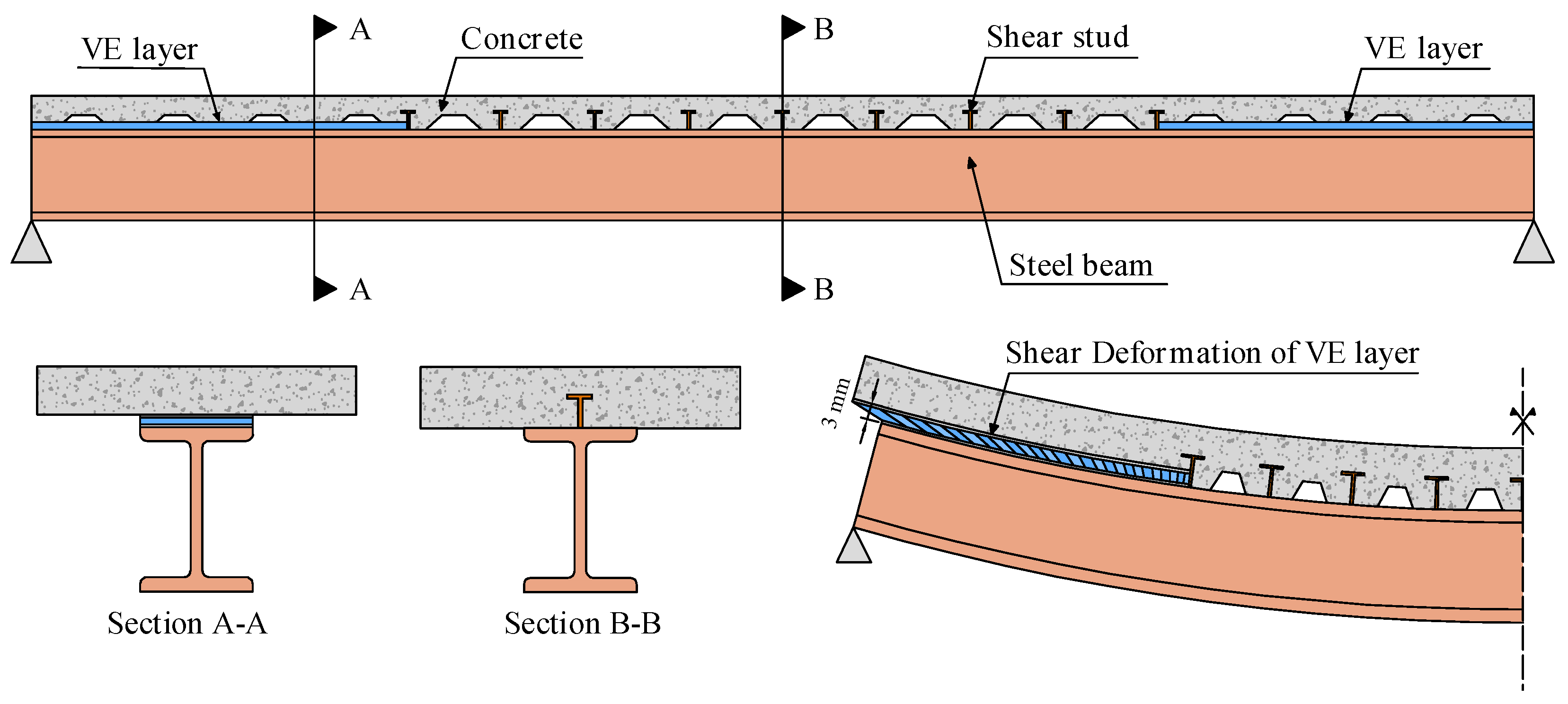
Figure 1e), and its applicability was described by Willford et al. [
22] (
Figure 2). This type of CLD treatment is the one studied in this paper. The major advance of this proposal over the previous ones was the location of the VE layer between the rib-deck concrete slab and the upper flange of the steel beam (as close as possible to the composite section centroid) where the shear strain to be achieved is maximum. Moreover, they recommended including the VE layer only for a percentage of the beam’s length near the supports, where the longitudinal shear strain is higher, whereas the central part of the composite beam remains connected to the shear using studs. Therefore, there is a trade-off between the achieved inherent damping and the loss of stiffness due to the partial shear connection in length. The CLD treatment itself used by ARUP has an overall thickness of 3 mm and is composed of two thin steel sheets of 1 mm that constrain a slim VE layer of 1 mm. Unlike previous applications, this CLD treatment was not conceived to be retrofitting solution but an integrated technology that needed to be considered when designing the composite floor. The optimal design of this CLD treatment and its integration into the design workflow of a composite floor were aspects not covered by Willford et al. [
22].
Thus, this paper aims to provide a methodology for the structural checking and structural optimization of composite floors prone to vibrate with this integrated CLD treatment. The main objective is to prove that the use of this CLD treatment enables overcoming the VSLS without adding great amounts of additional mass to the floor and minimizing its EC.
The structural optimization of composite floors has been researched by many authors using different optimization algorithms, Objective Functions (OFs), and problem constraints (which are the limits states (LSs) to be met by the floor). Initially, the authors used the weight and the cost of the floor as OFs. Zahn [
23], optimized the weight of a set of composite beams using two different codes. The VSLS was considered according to an early recommendation given by Murray in 1981 [
24] based on a heel drop loading. He concluded that vibrations were the sizing criterion for spans between 3 m and 6 m. Later, Kim and Adeli [
25,
26] optimized the economic cost of composite floors with a simple OF considering the influences of concrete, steel, and studs. They affirmed that the VSLS was checked but without providing details. The cost optimization performed by Klanšek and Kravanja [
27,
28,
29] used a complex OF accounting for material, energy consumption, and labor cost items required to manufacture a composite floor. They studied the use of different types of steel members for typical ranges of spans and loads, according to the Eurocodes but without considering the VSLS. The research developed by Kaveh and Ahangaran [
30,
31] followed a similar methodology as the one proposed by Zahn but they focused on testing the efficiency of novel meta-heuristic algorithms for structural optimization. Poitras et al. [
32] was the first author to include a widely accepted methodology to check the VSLS (the AISC Steel Design Guide 11 Floor vibrations due to human activity [
7]) for the optimization process of two composite floor examples. His work was used as a reference for another research performed by Kaveh and Ghafari [
33] where it was concluded that the vibrations were one of the critical LSs when designing a floor bay of 8 m × 10 m. Yossef and Taher [
34] performed another cost optimization of composite floors with castellated beams using a widely accepted methodology to check the VSLS (the SCI guideline Design of floors for vibration [
5]). In recent years, with the rise of life-cycle assessment, many authors have started to include the EC (measured in kgCO
2eq) of the floor as an OF to optimize. Roynon [
35] has presented a manual optimization of framed buildings minimizing their EC and giving reference values of kgCO
2eq/m
2 for steel framed floors (between 80–250 kgCO
2eq/m
2 for regular spans and 150–300 kgCO
2eq/m
2 for long-span floors). Drevniok et al. [
36] have developed an optimization methodology called ‘The Lightest Beam Method’ to study the amount of material that could have been reduced in a set of already designed and built steel floors without composite action. They consider the VSLS as a limitation in the natural frequency of 3 Hz, without assessing in detail the level of vibration. They concluded that the relaxation of serviceability requirements at the design stage could enable a reduction by more than 30% of the floors’ weight. Some authors as Whitworth and Tsavdaridis [
37] and Kravanja et al. [
38] have used the embodied energy (measured in J) to quantify the environmental impact of the floors. Finally, in the research performed by Gauch et al. [
39] different structural types of floors (made of concrete, steel, and timber) are designed and compared in terms of cost and EC obtaining interesting conclusions especially applicable to a decision-making stage of the design process. They again consider the VSLS by imposing a limit on the floor fundamental frequency of 4 Hz.
As a conclusion, it is clear that the VSLS should be properly taken into account in terms of the floor’s acceleration response according to currently accepted guidelines as [
5,
7] or [
6]. Thus, to the author’s knowledge, this paper is the first one addressing the multi-objective optimization (with the floor’s Weight and its EC as Ofs) of composite floors designed with and without integrated CLD treatments, and including a detailed verification of the VSLS.
The remainder of this paper is organized as follows:
Section 2 describes the elements of the type of composite floors to be optimized.
Section 3 outlines all the static limit states to be checked along the floor design.
Section 4 explains the workflow used to check the VSLS and how the CLD treatment has been optimally designed for each analyzed case.
Section 5 portrays the multi-objective structural optimization carried out describing the optimization procedure, the Ofs, and the optimization parameters used.
Section 6 describes a parametric study in which different square floor bays with different spans have been optimized with and without the use of CLD treatments to illustrate the proposed methodology. Finally,
Section 7 provides some conclusions.
2. Description of a Composite Floor with Integrated CLD Treatment
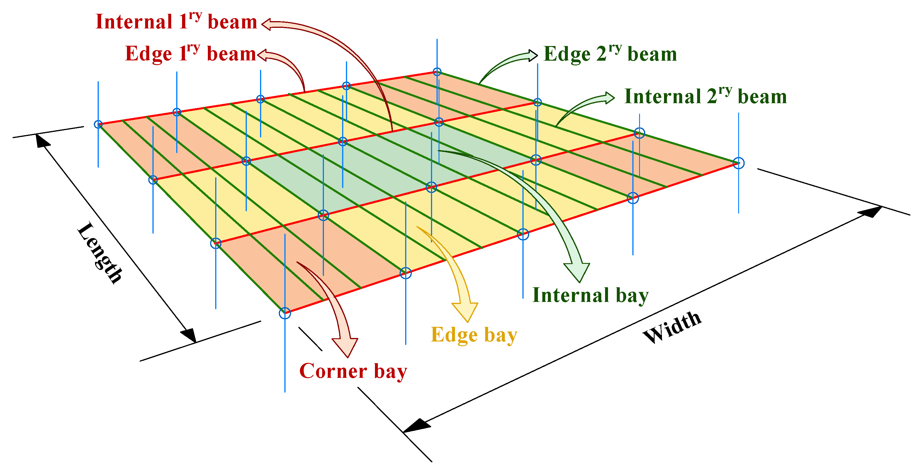
A composite floor with a given total length
L and a total width
B can be composed of different bays as represented in
Figure 3. A bay is defined as a floor part between 4 columns and is composed of primary (1
ry) beams spanning between columns and secondary (2
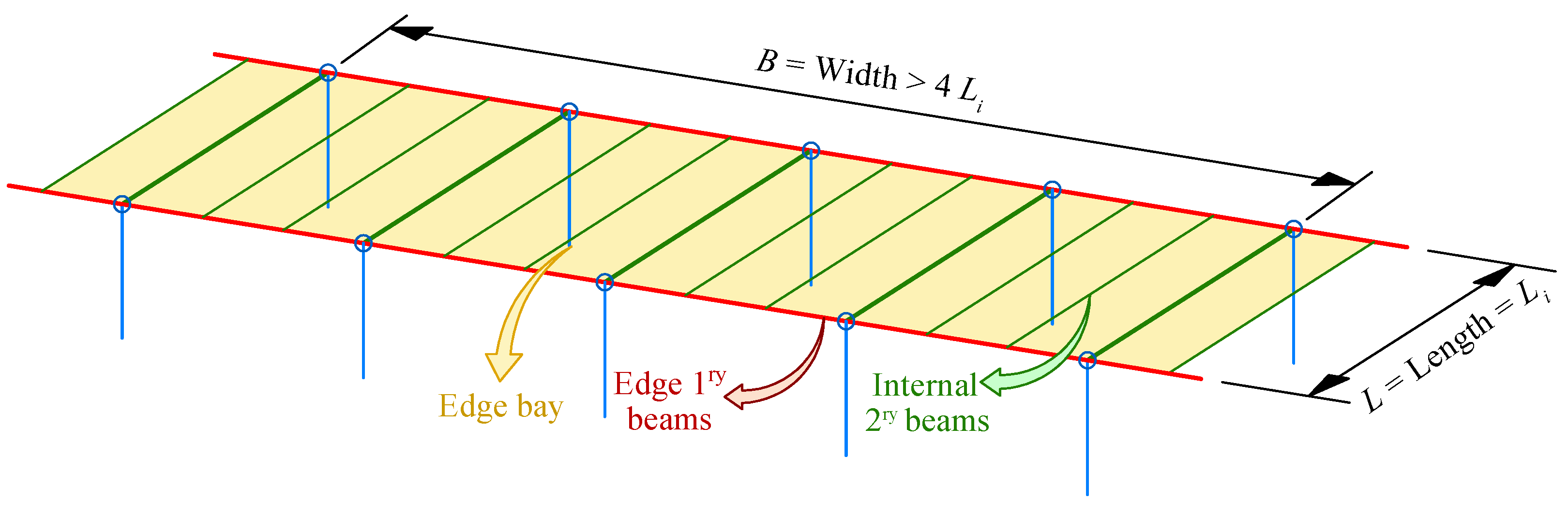
ry) beams that span between these first ones. There are 3 types of bays depending on their location, (i) corner bays, (ii) edge bays, and (iii) internal bays. The first two groups are usually more prone to vibrate as they cannot mobilize as much mass when vibrating as the internal bays.
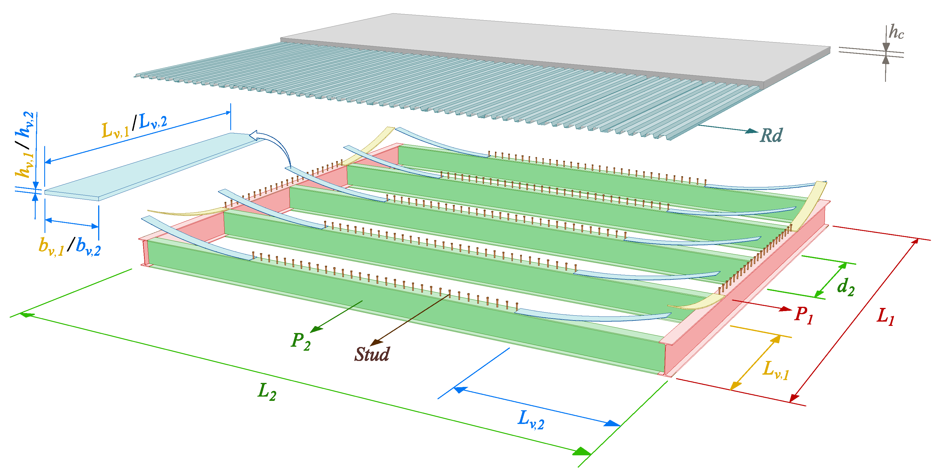
In this paper, the design of a composite floor with integrated CLD treatments is carried out according to the floor bay depicted in
Figure 4. A given floor bay is geometrically defined by the length of its 1
ry and 2
ry beams, here known as
and
, respectively; the number of 2
ry beams
and the distance between them
. The steel members of the floor are here defined through profile sections from the Universal Beam (UB) series (this catalog was chosen as it is large enough so that a meaningful optimization can be carried out). The profiles are represented with the integer values
and
which correspond with the profile positions in the UB catalog sorted according to the moment of inertia. S-275 steel has been considered. The concrete slab of the floor is defined by two parameters, (i) the commercial rib-deck used for the floor, which is defined with the integer value
(according to its position on the list of Cofraplus 60 rib-decks, with 4 different gauge thicknesses of 0.7 mm; 0.9 mm; 1 mm and 1.2 mm), and, (ii) the concrete slab thickness over the ribs in centimeters represented with the integer value
. The concrete grade used is C-30. Steel studs have been included along the central region of the 1
ry and 2
ry beams to ensure a certain degree of shear connection between the steel members and the concrete slab. In the 1
ry beams, the separation of studs depends on the required bending resistance of the composite section at mid-span. In the 2
ry beams their separation is equal to the distance between the valleys of the rib-deck. Ductile shear studs made of steel with a diameter of 19 mm, an as-welded height of 95 mm, and an ultimate limit stress of
= 450 Mpa, have been considered.
The CLD treatment has been included in all beams along a given length,
, near the supports (being
“i” an index used to refer the 1
ry or 2
ry beam). Thus, the percentages of beam” length treated with CLD are obtained as
, where
is obtained as follows:
The thickness of the VE layer of these CLD treatments,
, needs to be small so three possible values of 0.5 mm; 1.0 mm and 2 mm have been considered for this parameter based on [
40]. Moreover, the width of these VE layers,
, should be similar to the width of the top flange of their correspondent beams,
. For that reason,
must take a value within the continuous range that goes from
to
. The properties assigned to the VE material of the CLD treatment are in the range of commercial VE materials for vibration damping (for example, the HIP2, before cited [
40]) i.e., a storage shear modulus
of 0.5 mPa, a loss factor
with a value of 1 and a density of 1700 kg/m
3. The loss factor of this type of material is usually measured based on the standard testing method ASTM:E756-05 [
41].
In
Table 1 the main material properties used along the paper are listed indicating, the name of the material, the element in which it is used, and its main mechanical properties.
is used to denote the density of the material,
for the Young modulus of the steel,
for the Young modulus of the concrete,
is the yielding strength of the steel, and
is the ultimate tensile strength of the steel.
In this paper, for given a floor bay defined by a set of and , the rest of the floor parameters above described (, , , , , , , , , and ) are optimized to minimize two oFs, while meeting all the LSs of the floor design.
5. Optimization Problem Definition
In this section, the authors propose the definition of an optimization problem for the structural design of composite floors partially treated with CLD. The floor optimization addressed is a discrete multi-objective optimization problem with two OFs (
and
) depending on a vector
of seven design variables defined by integer numbers (from
to
), and with six design constraints defined by the functions
to
. The optimization problem can be formulated as follows:
where
and
are the functions to compute the mass of a floor bay and its embodied upfront carbon per unit of floor area, respectively. Additionally,
,
,
,
,
and
are aggregate functions of the LSs checked for the different floor elements, and are described in detail in the following subsection devoted to the constraints of the problem. They provide a value of 0 if the concerning LSs have been met and positive values if not.
5.1. Design Variables
The seven design variables are integers since the structural optimization of a floor is subjected to the adoption of discrete values on its geometrical parameters to ease the construction process of the floor.
The floor optimization performed assumes a given floor bay defined by fixed distances between columns and that belongs to a given floor with fixed total length (L) and fixed total width (B). This bay is optimized by finding the optimal values of the following variables: , , , , , and . The remaining floor-defining parameters are obtained when checking the different LSs as follows:
: the number of shear studs used in each beam is calculated to meet the bending ULS of the beam at mid-span.
and : the dimensions of the CLD treatment used in each floor beam are obtained to maximize the of each beam.
: the amount of hogging reinforcement of the slab is computed to meet the ULS of the hogging bending moment of the slab.
5.2. Objective Functions
Two objective functions have been minimized: (i) The mass of the floor bay per unit of area, , and (ii) the embodied upfront carbon of the floor bay per unit of area, . The choice of these two OFs is based on the fact that to tackle the vibration problem from the design perspective, two main strategies can be adopted: (i) to increase the mass of the floor, by thickening the concrete slab, which has a great impact on the floor’s but not much in the , or (ii) to stiffen the steel members of the floor, which increases much more the than the . This stays true when using low-strength concrete (with low cement content) and non-recycled steel, as in this case the carbon factor of the steel is much higher than the concrete one.
The computation of
has been carried out according to the guideline ’How to Compute Embodied Carbon’ by Gibbons et al. [
47]. This study has only considered the influence of the embodied upfront carbon of the floor (i.e., from modules A1 to A5 of the floor’s life-cycle). For the computation of
, the following floor elements have been considered: concrete slab, slab reinforcement, rib-deck sheet, steel beams, shear studs, and CLD treatment. Modules A1 to A3 (those belonging to the Product Stage of the life-cycle) are the main contributors to the final upfront EC of the floor. Thus, a list of the A1–A3 Carbon Factors used (denoted as
) for the
nth materials of the floor, is provided in
Table 4.
The floor studied is supposed to be built in a UK city. The steel and concrete have been assumed to be provided by a national and a local supplier, through road transport of 300 km and 50 km, respectively. An ‘A4 Carbon Factor’ for road transport of 0.10749 gCO2eq/kg/km has been used.
5.3. Design Constrains
Six different design constraint functions have been used:
,
,
and
for the ULS and DSLS of 1
ry and 2
ry beams, respectively;
for all the LSs of the rib-deck slab, and
for the VSLS of the whole floor. These functions are built using safety factor functions
(that compute for a given floor configuration
, all the
listed in previous sections) in combination with the following Modified Heaviside function
(that gives a value of 0 if the
value is lower than 1, and provides 1 if the input is greater or equal than 1):
Thus, the constraint equations used are defined as follows:
These functions provide a value greater than zero if not all the LSs involving them are fulfilled, and equal to zero if all the LSs are met. The function has two possible definitions depending on whether the impulsive acceleration wants to be limited.
5.4. Optimization Algorithm
The evolutionary optimization algorithm ‘Non-Dominated Sorting Genetic Algorithm II’, best known as NSGA-II, for constrained and discrete multi-objective optimization, has been used in this paper. The algorithm version used is available in the python library ‘pymoo’ and has been implemented according to [
49]. A random sampling of integer values has been performed to generate the initial solutions. A constraint handling method based on the principle ‘Feasibility First’ has been used to avoid the definition of any penalty function. This methodology was proposed by [
50] and uses a fitness function (applied to each solution) that depends on the current population. When tournament selection is applied to these fitness values, feasible solutions are always emphasized over infeasible ones. A simulated binary crossover based on [
50] with a crossover index
= 3, and a probability of crossover for each variable of
= 0.5, has been used. A polynomial mutation has been employed with a mutation parameter
= 3 and a probability of mutation
= 0.5. The histograms used for crossover and mutation have been rounded to deal with integer variables. Finally, for each optimization performed 100 generations with a population of 100, have been used.
6. Parametric Study
The optimization problem proposed has been used to develop a parametric study in which many different floor bays are optimized with and without CLD. This has been built by combining four different parameters which are needed to optimize a given floor bay:
: The length of the 1ry and 2ry beams of the floor. The parametric study has been focused on analyzing square floor bays, where . has been varied from 4.5 m to 19.5 m each 1.5 m, analyzing a whole set of 11 possibilities for this parameter.
: The limiting response factor of the floor bay to define the VSLS. Four different possibilities have been considered for . First, a , which corresponds to floor designs in which the VSLS has not been checked, here denoted as ‘Statically designed floors’. , which is the limitation used for regular electronic offices. is the limit used for quiet spaces like silent offices or libraries. Finally, would apply to hospital floors.
: The used to define the VSLS. Two possibilities are contemplated, which limits the impulsive and resonant floor responses, and which only limits the resonant response.
: This indicates if the CLD treatment has been integrated into the design. Two possibilities are studied, = CLD and = NO CLD.
The following vectors provide a summary of the four parameters used and the values they can adopt:
A total of 176 cases (resulting from combining all the different possibilities 11 × 4 × 2 × 2 = 176) have been analyzed. One particular case can be, for example, the one defined by the vector [9, 4, , NO CLD], which corresponds to a 9 m × 9 m floor bay, designed to comply with a maximum response factor of 4, including the impulsive and resonant responses, and without any integrated CLD treatment.
For each optimized floor bay seven design parameters result from the optimization problem if the CLD is integrated: , , , , , and . If the CLD is not used, this number reduces to five as and are set to 0.
The geometry configuration of the whole floor to which the floor bays optimized belong is a row of bays sharing a secondary beam between them, as depicted in
Figure 8.
6.1. Results
For each case, a multi-objective optimization has been performed.
Figure 9 and
Figure 10 provide the Pareto fronts of the achieved global optima for different floor spans, different vibration limitations and, with and without CLD treatment. The first one has been obtained using
and the second one making use of
. Shaded areas in green, blue, and red represent the difference in the Pareto space between the optimal designs obtained without and with CLD. The bigger these areas, the higher the effectiveness of the CLD treatment.
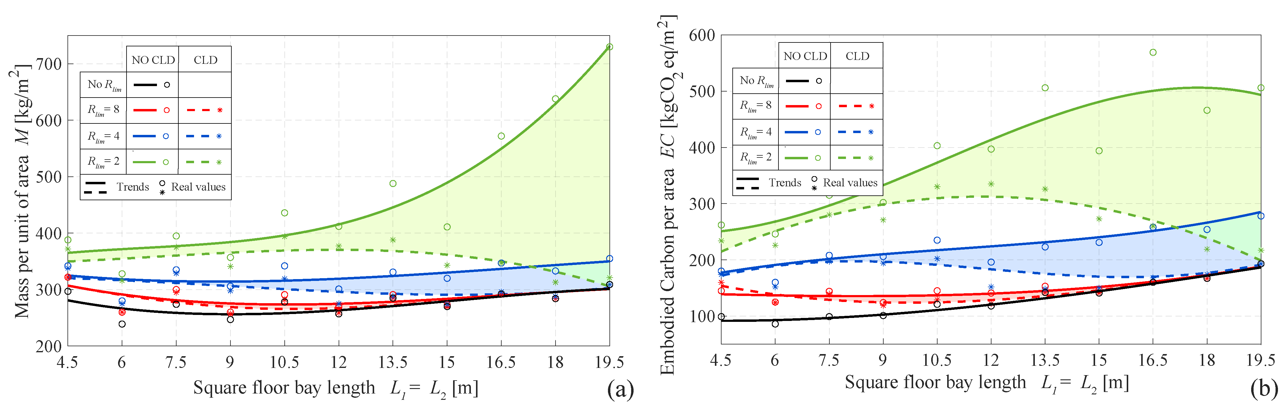
For each studied case, the lightest designs (those with an optimal mass
M and located at the left edge of each Pareto front) have been represented in terms of their
M and
depending on the span.
Figure 11 and
Figure 12 correspond to floors designed using
and
, respectively. Polynomial trend curves have been included in these charts for a better interpretation of the results. The shaded areas in these figures have the same function as in the previous ones.
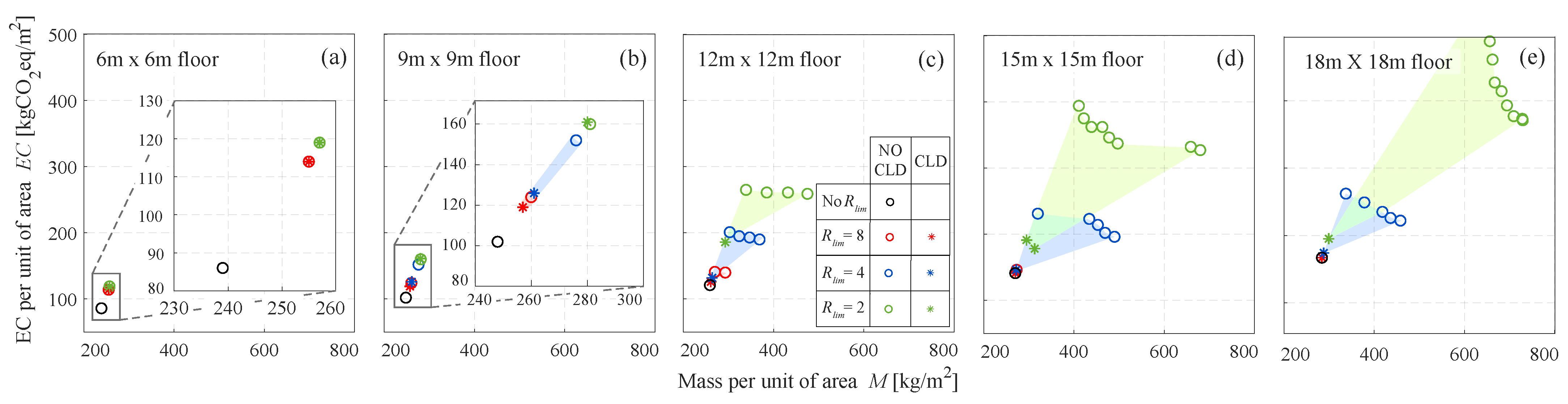
Finally, within the previous figures, the black circles and lines represent the static designs in which the VSLS has not been checked. When imposing a more restrictive vibration limitation, these floor designs must be changed in terms of mass, stiffness, or damping to meet the new VSLS. To provide a meaningful interpretation of these, the
and the
of these statically designed floors have been represented together with their
and
in
Figure 13a,b, respectively. Shaded areas in
Figure 13a represent the vibration limitation used in the parametric study. Shaded areas in
Figure 13b represent the frequency restriction of 3 or 4 Hz that some design codes impose on long-span floors to avoid excessive low-frequency vibrations.
6.2. Discussion
The first finding to note in
Figure 9,
Figure 10,
Figure 11 and
Figure 12 is that the statically designed floors are the ones with less
M and
. Also, the Pareto front in these cases converges to one point, as the concrete slab is kept as light as possible.
It is also clear from the results obtained that the more restrictive the vibration limitation, the higher the oversizing of the floor to meet the VSLS.
In floors designed without CLD, when imposing more restrictive values (especially 4 and 2), the Pareto front begins to open. This widening effect is more evident in two cases:
In long-span floors with span > 12 m (as can be seen in
Figure 9d,e and
Figure 10d,e). This can be explained by observing in
Figure 13a,b that long-span floors have a dynamic response dominated by
. They also have low values of
. On the one hand, the excessive resonant vibration may be tackled by stiffening the steel profiles of the floor (which implies a high
cost, but has a low repercussion in
M) to increase its
and thus, reduce the amplitude of the exciting human harmonic
. On the other hand, a solution with less
cost but more impact on the final floor’s
M, is to thicken the concrete slab to reduce the floor resonant response. These two possibilities are the extreme solutions of the Pareto fronts.
In short-span floors designed using
(compare, for example,
Figure 9a,b with respect to
Figure 10a,b). Again, looking at
Figure 13a,b, it is noticeable that short-span floors have higher values of
and
, higher values of
, and lower values of
. In these floors,
can be optimally reduced with a minimum stiffening of the floor that effectively rises
the right amount to meet the VSLS (this explains why in
Figure 10a,b, the Pareto front converges to 1 point). Nevertheless, reducing the floors’
requires, either a major stiffening of the floor, (which reduces the value of the effective impulse loading
or a substantial increase of its
(to reduce the impulsive response). Hence, controlling the impulsive vibration
produces a significant oversizing of short-span floors compared to when it is not controlled (see results of
Figure 11 and
Figure 12 for span values lower than 12 m).
Regarding the effectiveness of the CLD integration in the final design of the floor, the following conclusions may be extracted:
7. Conclusions
This paper studies the integration of CLD treatments into the design workflow of composite floors prone to vibrate. This treatment consists of a thin VE layer included between the steel member and the concrete slab of composite floor beams for a proportion of their length near the supports. This technology enables increasing the floor-damping ratio when vibrating in vertical bending modes, which allows for the reduction in the amount of additional mass or stiffness typically increased to overcome the VSLS.
A constrained discrete multi-objective optimization problem has been proposed to design a floor bay with different CLD treatments applied on their 1ry and 2ry beams. Seven design variables of the floor have been considered The design constraints of the problem are the different LSs of the floor, and two OFs have been used: the embodied carbon and the mass of the floor per unit of area.
Finally, a parametric study for different square floor bays, with spans varying from 4.5 to 19.5 m, has been carried out to compare the optimal structural solutions obtained with and without making use of the CLD treatment. Four different limits of vibration have been imposed from less to more restrictive. The results obtained indicate that for long-span floors (>12 m) the reduction in terms of mass and EC is substantial. The CLD enables the reduction in the structural oversizing in terms of mass from values of 100% or 50% to around 20% or 2% for floors meeting a VSLS limited by R factors of 2 or 4, respectively. Moreover, when the impulsive vibration of the floor is not checked, this enhancement is even higher.
Future work will be focused on studying the efficacy of this CLD treatment when implemented on lightweight concrete and timber floors.


 ,
, 


