Article

A Large Force Haptic Interface with Modular Linear Actuators

1
Department of Mechanical System Engineering, Jeonbuk National University, Jeonju 54896, Republic of Korea
2
Advanced Transportation Machinery Research Center, Jeonbuk National University, Jeonju 54896, Republic of Korea
3
Department of Mechanical Science and Engineering, University of Illinois at Urbana-Champaign, Urbana, IL 61801, USA
4
Department of Electrical and Computer Engineering, University of Illinois at Urbana-Champaign, Urbana, IL 61801, USA
*
Author to whom correspondence should be addressed.
Actuators 2023, 12(7), 293; https://doi.org/10.3390/act12070293
Submission received: 30 June 2023 / Revised: 12 July 2023 / Accepted: 13 July 2023 / Published: 18 July 2023

Abstract

:
This paper presents a haptic interface with modular linear actuators that addresses the limitations of conventional devices based on rotary joints. The proposed haptic interface is composed of parallel linear actuators that provide high backdrivability and small inertia. The performance of the haptic interface is compared to those of conventional mechanisms in terms of force capability, reflected inertia, and structural stiffness. High stiffness, large range of motion, and high force capability, which are in trade-off relationships in traditional haptic interfaces, are achieved. The device can apply up to 83 N continuously, i.e., three-fold more than most haptic devices. The theoretical minimum haptic force density and stiffness of the proposed mechanism are 1.3 to 1.9 and 37 times those of the conventional mechanisms under similar conditions, respectively. The system is scalable because the structural stiffness depends on only the timing belt stiffness, whereas that of conventional haptic interfaces is inversely proportional to the cube of the structural length. The modular actuator enables changes in the degrees of freedom (DOFs) for different applications. The proposed haptic interface was tested through an interaction experiment in a virtual environment with virtual walls.

1. Introduction

A haptic interface allows for physical interaction between a user and a virtual environment. The hardware and controller determine the transparency and stability in rendering an environment. Although advanced control algorithms can enhance the performance of haptic interfaces [1,2,3,4], transparency and stability conflict in the sense of control, as introduced in [5]. Therefore, the fundamental limitation of a haptic system is determined by the physical system of the device, including the actuator bandwidth, structural stiffness, friction, inertia, and range of motion (ROM). Haptic interface hardware design always introduces trade-offs between these parameters. A large ROM requires long linkages, which are associated with low structural stiffness or large reflected inertia from the linkage mass. A large force capability requires high gearing ratios, which are associated with high friction and reflected inertia [6]. These trade-off relationships are dominated by the actuators, transmissions, and sensors, and depend on the mechanism that combines the components of a haptic interface.
Serial mechanisms with rotational actuators, which are widely used in robotic arms and exoskeletons, can be considered as the mechanism of a haptic interface [7,8,9]. This mechanism is simple and allows for a large ROM because interference between linkages can be prevented by an appropriate design. However, cumulative linkage deformation (principally bending) negatively affects the displayable stiffness at the end-effector. Thus, large inertia of the linkage is required to ensure high stiffness. While it is necessary to increase the gear ratio of the actuator to handle the large inertia, this reduces the backdrivability of the haptic interface.
For this reason, most commercial haptic interfaces use parallel linkage-based mechanisms such as the delta mechanism [10] or four-bar linkages [11,12,13]. Parallel linkages enhance structural stiffness of the system while limiting ROM because of their structural complexity. The commercial haptic interfaces cited above show force capabilities of less than 20 N because high reduction ratio gears are avoided to ensure high transparency. The 3-DOF Orthogonal Tripteron mechanism introduced in [14] allows fully decoupled motion of all three axes; thus, the kinematics and dynamics are simple. However, the stiffness is limited because of the bending of linkages. Interference between rotational linkages and the user becomes problematic when the system is upsized. The actuators are high-speed small-torque motors with gear reductions.
Admittance control with force feedback could be an option for reducing the effects of friction imparted by gearing. This yields lightweight and high-force systems with small actuators. However, the haptic feedback bandwidth and stability are limited by the sensing rate and sensor noise. A high gear ratio and the resulting reflected inertia limit the bandwidth at high frequency [15]. Perret et al. [16] used a tendon-driven haptic interface to enable room-size ROM. However, the stiffness was limited by the long tendon, and the tendons could interfere with the user. Brake-and-clutch systems can deliver high force with backdrivability [17,18], but can only render resistive environments. A hybrid actuation system with a clutch and an active actuator could render a very high stiffness while capable of displaying a small-force active environment when the clutch is not activated. However, only infinite stiffness environments could be delivered, and would not allow modulation of perceived contact compliance when the clutch is activated [19].
Certain non-commercialized haptic interfaces have targeted high force capabilities, ROMs, and high backdrivability [15,20,21]. One hybrid actuation mechanism separated high- and low-frequency force generation using different sizes of actuators for the base part and distal side [15]. However, the system was highly complex, and it required control efforts in contact with high stiffness virtual objects. Lee et al. used parallel four-bar linkages that can provide a large ROM and high force capability and stiffness [20]. However, gears with high reduction ratio were used to enhance the force capability, which was associated with large reflected inertia of the actuator at the end-effector side along with friction. Thus, it had a high overshoot and long settling time. Barnaby et al. developed a haptic interface with backdrivable actuators, timing belt reductions, and a four-bar linkage mechanism [21]. While the system showed high backdrivabilty, the force was as low as those of commercial haptic interfaces.
All of the above-mentioned haptic interfaces used rotational actuation mechanisms. This introduces bending deflection of the linkages, which is a dominant deflection of the structure. Although the actuators provide high stiffness, the low structural stiffness limits the displayable stiffness at the extremity of the linkages.
We aim to develop a large force haptic interface for the teleoperation system shown in Figure 1 [22,23,24]. The system utilizes the user’s skills to explore the dynamic balancing and manipulation of the teleoperated robot. The user and robot are synchronized, with human motion used as the reference; the user receives feedback through a human–machine interface (HMI). The kinematic and dynamic differences between human and robot reduced models, such as a linear inverted pendulum and wheeled inverted pendulum model, are used for control. With the synchronized teleoperation system, the user can achieve dynamic manipulations such as pushing a heavy object by leaning against it, thereby leveraging body weight and inertia. A human can generate almost 140 N of push force under practical conditions and even more under certain circumstances [25]. It is necessary to provide such a large force to the user’s hand to make the human and robot dynamically similar; this significantly affects the dynamics of both the human and the robot. To leverage the full balancing and manipulation capacities of a human, the ROM should cover roughly a human quadrant. This is difficult to achieve with existing haptic interfaces without scarifying stiffness, considering the limitations of rotational mechanisms.
In this paper, we propose a novel haptic interface based on modular linear actuators that can provide a large force, large ROM, high mechanical backdrivability, small reflected inertia, and high structural stiffness (Figure 2) as a part of the human–robot interaction system. The mechanism is compared to those of conventional serial and parallel mechanisms in terms of the available force over reflected inertia. The proposed mechanism is scalable because high structural stiffness is ensured by the linear actuator-based mechanism regardless of the ROM; in addition, the reflected inertia is small. The actuator ensures high force capability and backdrivability because of the timing belt-based reduction. A gimbal handle that connects two modular linear actuators and ensures zero residual torque is introduced as an example for the proposed haptic interface design. Considering the parallel linear mechanism, the DOFs can be varied by adding additional modular linear actuators and modifying the handle design without being significantly constrained by structural stiffness or the inertia of the system.
The remainder of this article is organized as follows. In Section 2, the design of our haptic interface with linear actuators is introduced and analyzed in comparison to conventional rotational mechanisms. The performance of the backdrivable modular linear actuator is addressed in Section 3. The results of experiments with a virtual object are presented in Section 4 along with a discussion. Finally, Section 5 concludes the article.

2. Mechanism Design and Analysis

2.1. Design

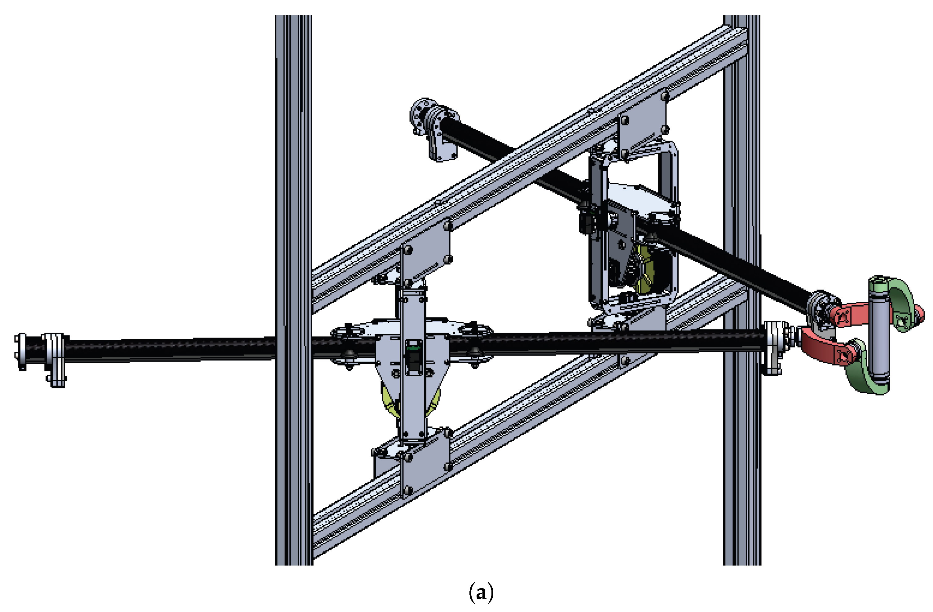
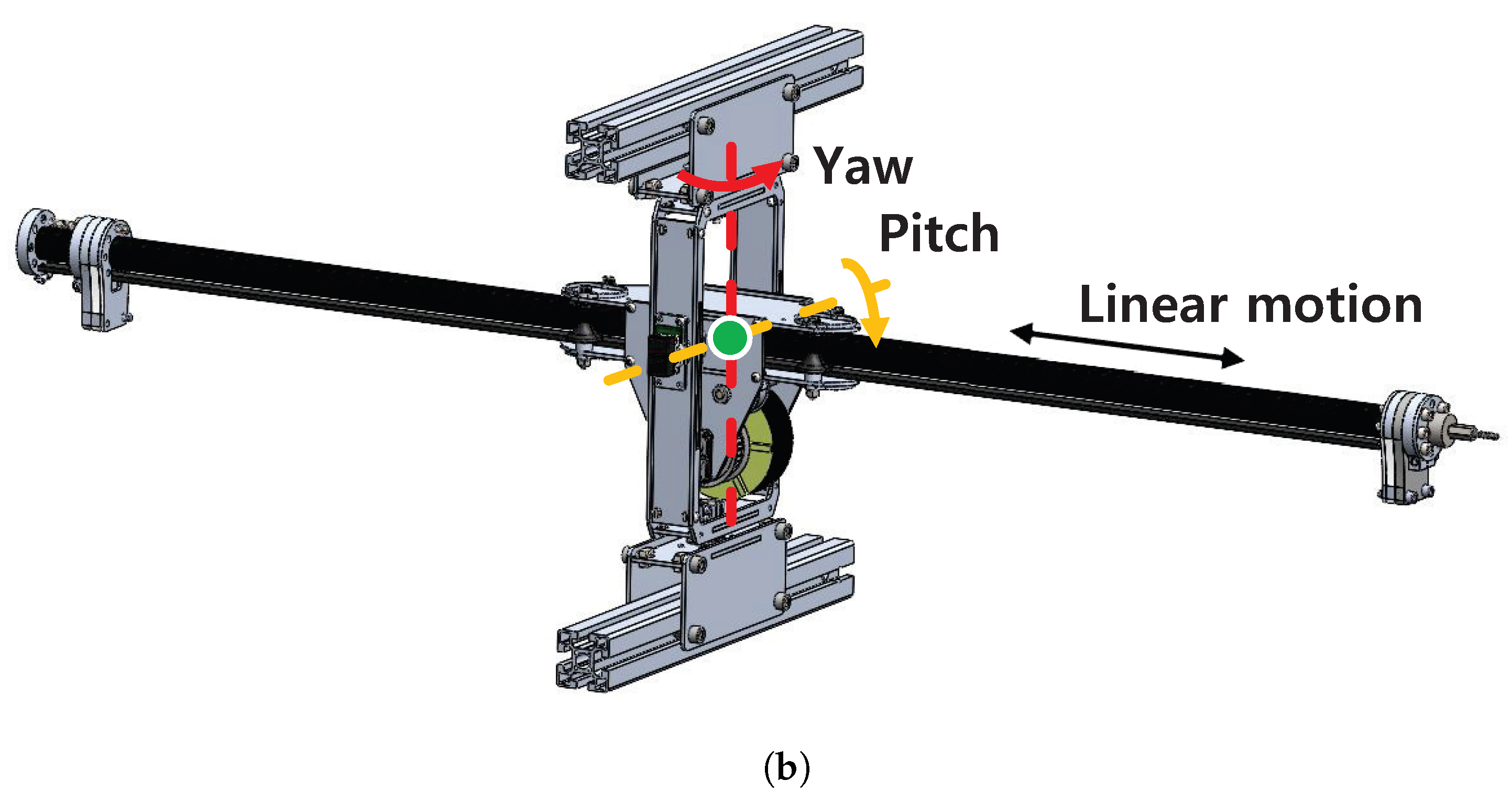
The main limitations of previous haptic systems are induced by friction and inertia from gearing [6] as well as by low stiffness caused by bending of the linkages. We propose a haptic interface with modular linear actuators that can overcome these limitations (Figure 3a). The modular linear actuators proposed in [22] are connected in parallel to the end-effector. The actuator has high-torque low-inertia motors and a timing belt-based reduction system that together enable a high force capability of up to 100 N and backdrivable actuation with small friction. Thus, the haptic interface is very transparent. The actuator can be rotated with a 2-DOF gimbal that holds a carbon fiber rod with flexures and rollers to constrain the rod and other parts in terms of rotation while allowing linear actuation (Figure 3b). Details of the actuator design are provided in [22].
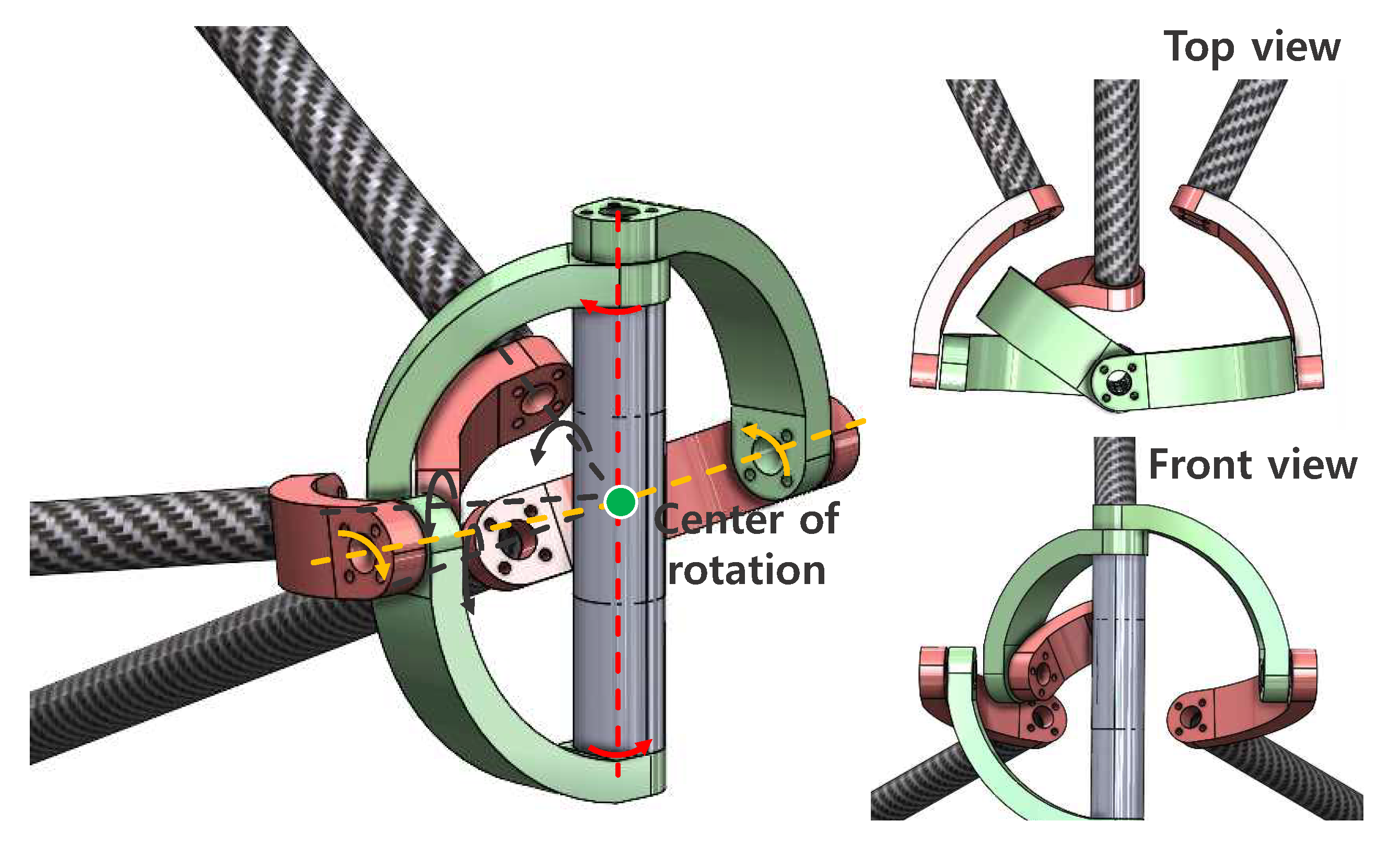
The gimbal handle constrains two linear actuators and allows 3-DOF free rotation of the user’s hand. All rotational axes of the gimbal handle as well as linear actuator axes cross the center of rotation of the handle. Thus, only desired forces are delivered to the user’s hand and there is no residual torque. The gimbal handle allows only small structural deflections, as the size of the handle is small compared to the range of linear actuators. Deflection of the linear actuators is very small because only axial loads are applied via the gimbal. The axial stiffness of the linear actuator is dependent on the timing belt stiffness, which is usually very high and has a wide range of choices. Further, the parallel actuation mechanism enhances the overall stiffness at the end-effector. The end-effector ROM can be enlarged by increasing the span between the linear actuator gimbal and the linear motion range of the actuator. This does not compromise inertia or friction, as the available force is not changed by the ROM and both the timing belt and linear rod of the actuator have very little inertia. Thus, the system is scalable, unlike previously developed systems mentioned in Section 1, satisfies stiffness requirements, and affords a large ROM without significantly increasing the inertia. Table 1 lists the detailed specifications of the proposed haptic interface. The total linear inertia of moving parts, which include the rod, timing belt, and belt tensioner, is 0.533 kg. The gimbal handle linkages are manufactured using a 3D printer and the joints are composed of metal parts.
The proposed haptic interface design can be expanded to devices with more DOFs and feedback forces/torques by changing the number of modular linear actuators and employing a suitable end-effector to connect the linear actuators. As an example, a 3 DOF Agile Eye-like [26] gimbal with three modular linear actuators could be applied (Figure 4). The advantage of the agile eye-like gimbal designs proposed here is the absence of residual torque even though the system has fewer DOFs than six. Stewart platform-type mechanisms [27] with six linear actuators and universal joints can be used if six DOFs are required. The actuator of a Stewart platform typically has high inertia and low backdrivability, as significant reduction is used with a focus on precise position control and stiffness. This limitation can be overcome by our linear actuator. However, this paper focuses on the evaluation of the manipulator. The comparative design of these kinds of handles, including those for other mechanisms, is not described in detail. In this paper, a 2-DOF prototype is analyzed for comparison with conventional mechanisms.

2.2. Analysis

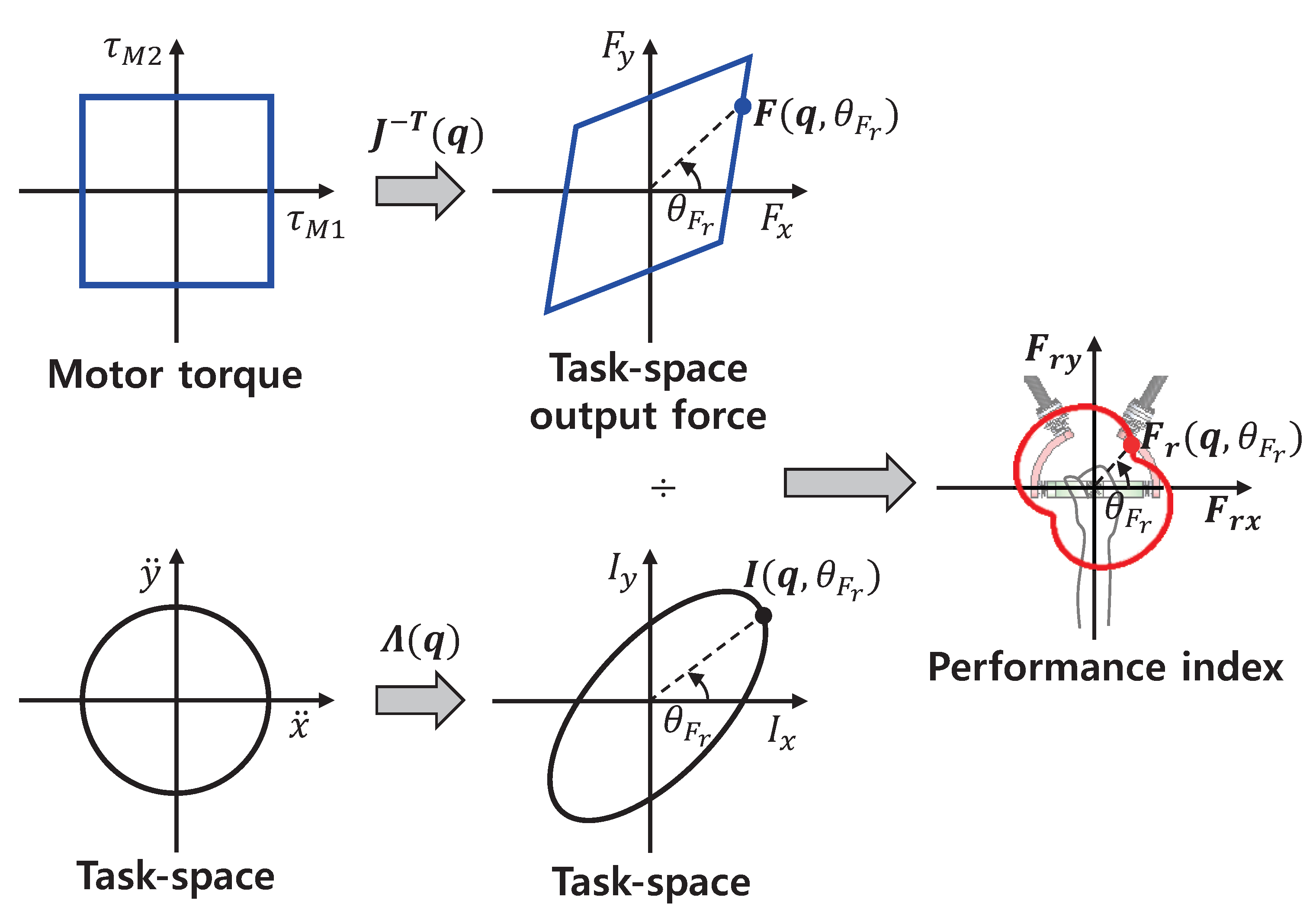
The advantages of the linear actuator-based haptic interface as compared to conventional rotational mechanisms are discussed next. The key metric is the reflected inertia, as the high-frequency performance of a haptic interface is dominated by inertia [15]. The force capability is important as well, as high force is a key requirement of many applications. Thus, we introduce the concept of Haptic Force Density (Figure 5), i.e., the force capability per unit of reflected inertia:
F r ( q , θ F r ) = u | F ( q , θ F r ) | | I ( q , θ F r ) | ,
where u is the unit vector corresponding to the angle θ F r , q is the actuator displacement vector, and F ( q , θ F r ) is the force that the device can generate at the end-effector in the quasi-static state, calculated as follows:
F ( q , θ F r ) = J T ( q ) τ
where J is the 2 × 2 Jacobian derived from the 2D end-effector position. The mechanism was modeled on a 2D plane aligned with the two linear actuator axes. I ( q , θ F r ) , which is the reflected inertia perceived by the user when the end-effector is back-driven with unit acceleration (1 m/ s 2 ), is calculated as [28]:
I ( q , θ F r ) = J T ( q ) M J 1 ( q ) x ¨ = Λ ( q ) x ¨
Here, θ F r indicates the direction of the generated force, which corresponds to a set of actuator torques τ or the direction of the back-driven task-space inertial force, while M is the inertia matrix determined by the actuator inertia and the system mechanism. The characteristics of the haptic force density F r ( q , θ F r ) are varied by the actuation mechanism, as F r ( q , θ F r ) is related to the Jacobian determined by the geometry of the device.
A higher F r ( q , θ F r ) indicates that the displayable force magnitude in a specific direction u that corresponds to the angle θ F r is larger compared to that of the reflected inertia when the haptic device is backdriven by the user in the same direction. A haptic device can render high forces with high haptic force density F r ( q , θ F r ) in comparison to its perceived (reflected) inertia, meaning that the user feels less inertial resistance at higher haptic force density at the same available force. This implies that the system is probably more transparent, as the inertia is small compared to the available force. Usually, haptic devices have ( a ) negligible perceived inertia and can only generate small forces due to a small gearing ratio (<10:1), or ( b ) can generate very high forces at the expense of very large passive reflected inertia by employing gearboxes with a large gearing ratio (>100:1). In either case, the haptic force density is small. In this paper, we focus on increasing the force capability without inflating the task space inertia of the device.
Figure 6 shows the force capability, reflected inertial force, and their ratio of a haptic interface with respect to (a) a parallel linear mechanism (this work), (b) a serial rotational mechanism, and (c) a parallel rotational mechanism. The motors are assumed to be at the bases, minimizing the inertia induced by the motor mass. The parallel linear mechanism represents the haptic interface mechanism proposed in this paper (Figure 6a), which has two passive rotational joints ( θ 1 , l and θ 2 , l ) and two linear joints actuated by the motor ( l 1 , l and l 2 , l ). Small rotational inertia is assumed because most of the mass (the motor and metal parts) are near the gimbal center. Thus, the linear actuator dynamics dominate the system, and are considered in the inertia matrix M . The other two mechanisms are conventional haptic interface designs utilizing rotational actuation mechanisms. In a serial rotational mechanism [7,8,9], the first motor actuates the first joint, which corresponds to θ 1 , s , and the second motor is attached to the first link (Figure 6b). The second motor rotates the second joint ( θ 2 , s ) relative to the first linkage. In contrast, the motors of the parallel rotational mechanism are independent (Figure 6c). Both motors are fixed to the base and independently connected to the two joints. Thus, each joint motion depends only on the motor motion corresponding to the joint. The parallel rotational mechanism can be considered as a linearized version of linkage-based mechanisms [10,11,12,13,20,21] under the assumption that the transmission through the second joint is rigid enough.
The link lengths of the rotational mechanisms were set to 600 mm each to cover the required ROM (600 mm × 600 mm), i.e., from the shoulder to the maximum arm extension, without significant singularity. The same motor as in our linear actuator-based haptic interface was assumed. The gear ratios were 21:1 and 18:1 for the serial and parallel rotational mechanisms, respectively. These ratios were selected to generate the same minimum force of the parallel linear mechanism at the home positions shown in the figure in order to ensure a fair comparison.
The blue lines in Figure 6 are the available force at each position in all directions ( F ( q , θ F r ) ) , while the black ellipsoids denote the reflected inertia when the end-effectors are backdriven with unit acceleration ( I ( q , θ F r ) ). The haptic force density F r ( q , θ F r ) was calculated by dividing the force by inertia for all directions. As shown in the figure, the force and inertia characteristics differ depending on the mechanism. The parallel linear and rotational mechanisms show Cartesian coordinate-based characteristics, while the serial rotational mechanism has the characteristics of polar coordinates. The parallel mechanisms in Figure 6a,c exhibit more even force and inertia distributions than the serial mechanism, although visual comparison with separate figures is difficult.
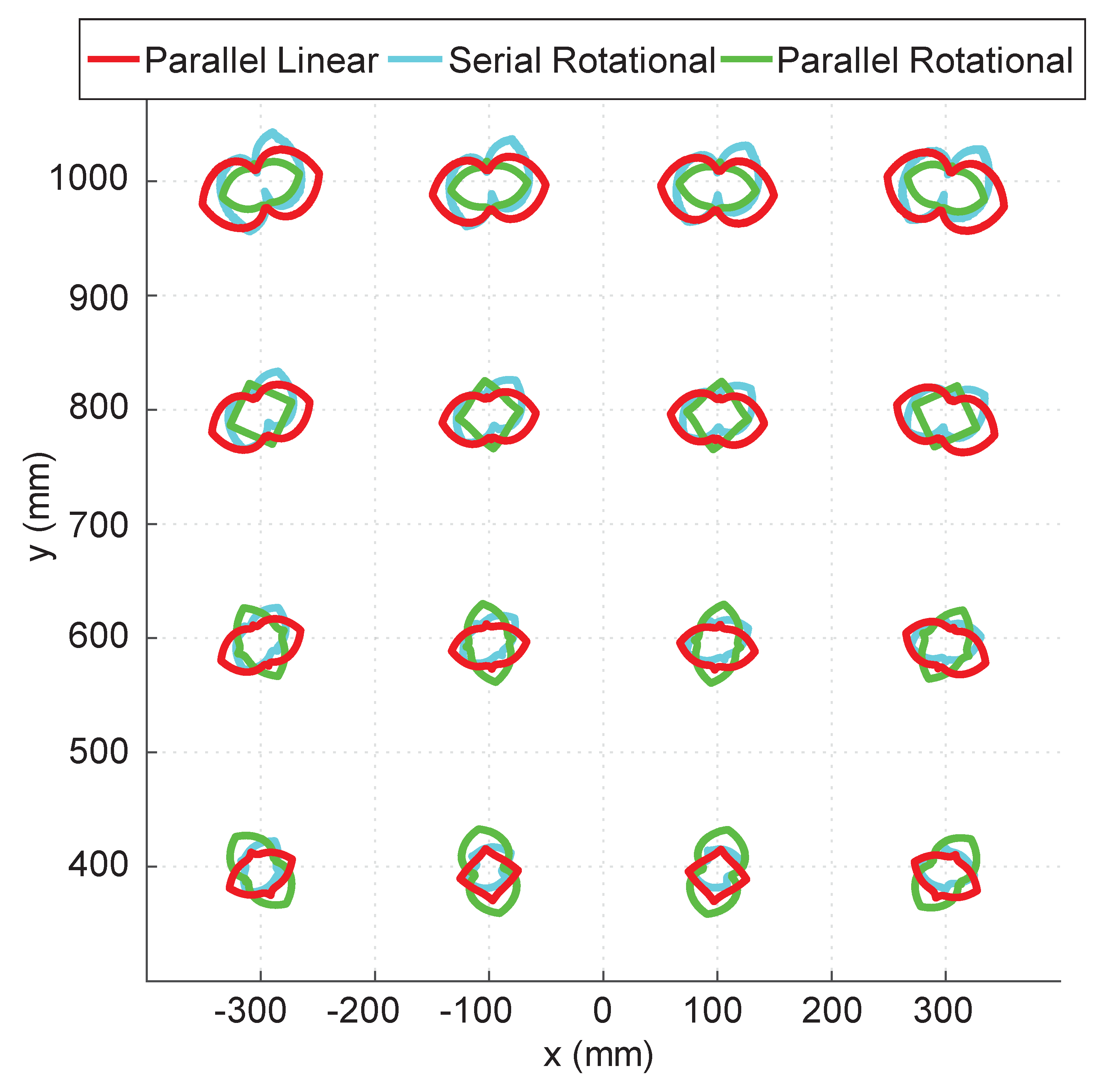
The haptic force density of the three mechanisms are overlapped in Figure 7 for easier comparison. The parallel linear mechanism usually has the largest haptic force density. The relative haptic force density of the parallel linear mechanism becomes higher along the y direction compared to those of other mechanisms. This is advantageous for a haptic interface that requires a wide ROM. The advantage of the proposed system is apparent when the minimum values of the haptic force density are compared. The minimum F r ( q , θ F r ) values are 0.875, 1.299, and 1.706 for the serial rotational, parallel rotational, and parallel linear mechanisms, respectively; this implies that the parallel linear mechanism provides a better haptic experience in terms of the force capability over the reflected inertia.
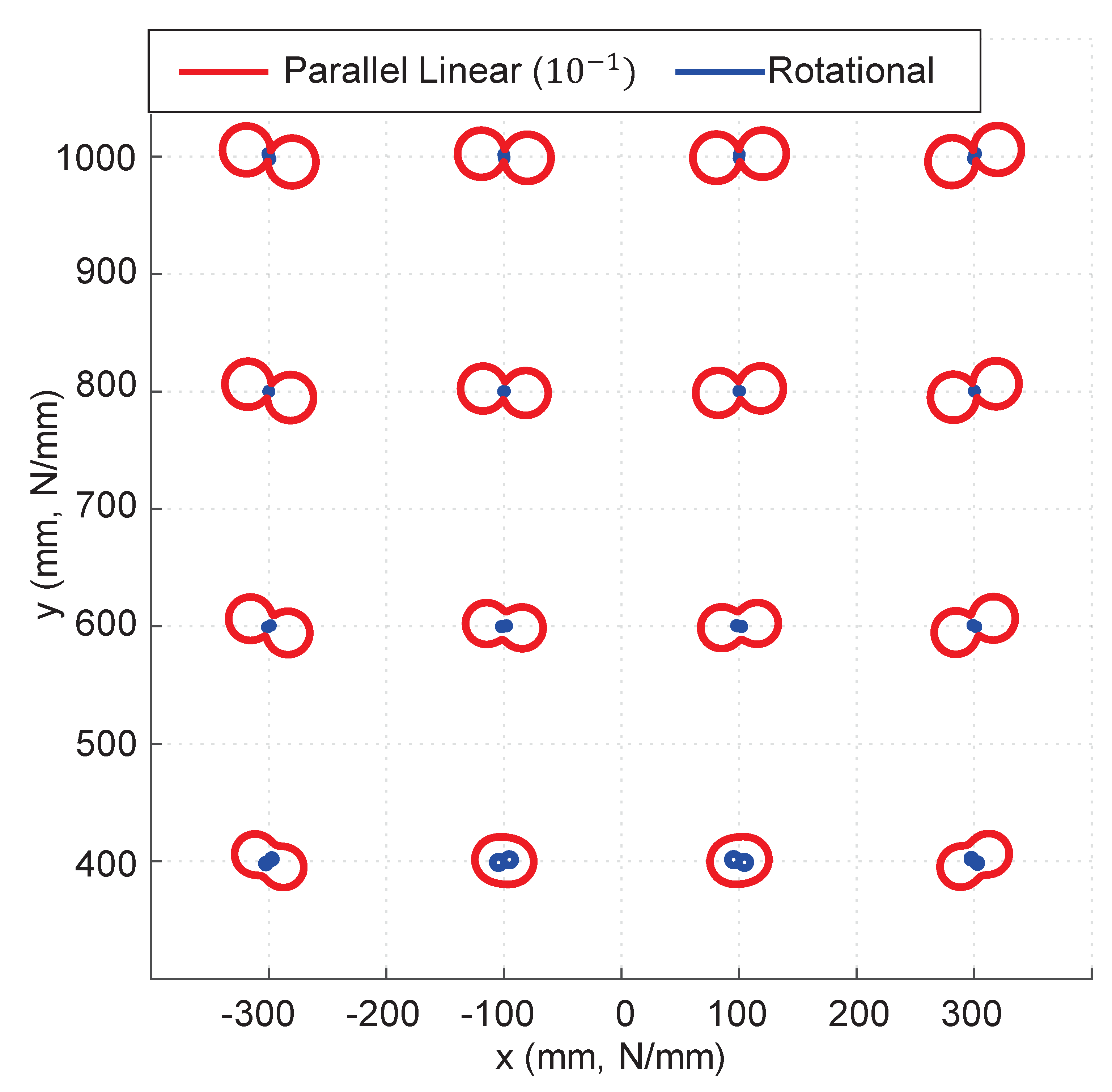
The other advantage afforded by the proposed haptic interface mechanism is structural stiffness. As the force is delivered to the end-effector along a linear axis, there is no bending deflection for the linear actuator. As the linear stiffness is determined by the timing belt stiffness, the resulting end-effector stiffness can be as high as that of the timing belt. Figure 8 shows the structural stiffnesses of the linear parallel and rotational mechanisms. Here, both the rotational and parallel linear actuators are fixed at several target points. The rods of the rotational mechanisms have the same dimensions and properties of the carbon fiber rod as the proposed 2-DOF haptic interface. A 1-mm displacement is applied to the end-effectors in all directions. The blue and red lines are the resulting force exerted by the displacement, which can be interpreted as the structural stiffness of the mechanism in units of N/mm. The axial deformation and bending of links were used for the stiffness calculation. The passive joints were assumed to be rigid for both mechanisms. Note that the stiffness of the parallel linear mechanism is scaled to 1/10 for easier visualization. As shown in Figure 8, the structural stiffness of the parallel linear mechanism is significantly greater under all configurations. The minimum stiffness of the rotational mechanism was 1.29 N/mm, while that of the linear parallel mechanism was 47.6 N/mm. This implies that the linear parallel mechanism can provide a high force bandwidth with superior structural stiffness, resulting in small inertia.
The bending stiffness of the linkage determines the stiffness of the rotational mechanism, as most linkage deflection is attributable to bending, which is proportional to the cube of the linkage length as follows:
k b e n d i n g 1 / l l i n k a g e 3
where k b e n d i n g is the bending stiffness and l l i n k a g e is the linkage length. On the other hand, axial deflection of a linkage is negligible compared to the bending deflection, as the axial stiffness k a x i a l is proportional to the inverse of the length as follows:
k a x i a l 1 / l l i n k a g e
Because the proposed parallel linear mechanism transmits force along the axial direction of the linkage via the timing belt, the stiffness is determined by the timing belt, which has a very high stiffness that is inversely proportional to the length, similar to the axial stiffness of the linkage.
Thus, the linear parallel mechanism can enlarge the ROM without sacrificing inertia, while the rotational mechanisms should increase inertia to satisfy the required stiffness. The stiffness of conventional rotation joint mechanisms can be enhanced by introducing parallel linkages, such as the delta and five-bar linkage mechanisms in many of the haptic interfaces introduced in Section 1. However, multiple kinematic loops can only linearly enhance stiffness by the number of parallel link sets; stiffness can be reduced more aggressively by using the inverse cube of the linkage length. The results of this stiffness analysis imply that the proposed parallel linear mechanism is scalable, while conventional rotational mechanisms are not.

3. Analysis of the Modular Linear Actuator

Linear actuators dominate haptic interface performance because they are connected to a small gimbal handle associated with small deformation and inertia. In this section, the inertia, force, friction, force bandwidth, and available stiffness of the actuator are analyzed to verify the actuator’s performance.
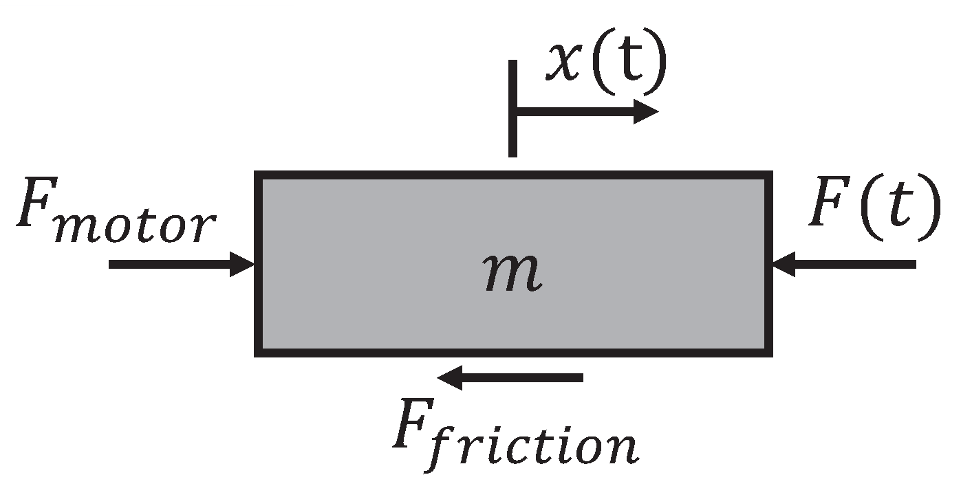
The actuator was modeled as a linear system with lumped inertia of the rotor, rod, idler pulley, timing belt, and tensioner in addition to Coulomb and viscous friction of the bearings (Figure 9). The motor torque was assumed to be linearly proportional to the applied current. The output force F ( t ) of the actuator applied to the environment can then be obtained from the equation of motion:
F ( t ) = F i n e r t i a F f r i c t i o n + F m o t o r
where
F i n e r t i a = m x ¨ ( t )
F f r i c t i o n = F C o u l o m b s i g n ( x ˙ ( t ) ) + a v i s c o u s x ˙ ( t )
F m o t o r = K m u ( t )
Here, x is the linear travel distance measured by the motor encoder and transmission geometry, m is the reflected inertia of all actuated parts of the linear actuator, F C o u l o m b is the Coulomb friction coefficient, a v i s c o u s is the viscous friction constant, K m is the motor constant, and u is the control input for the motor driver.
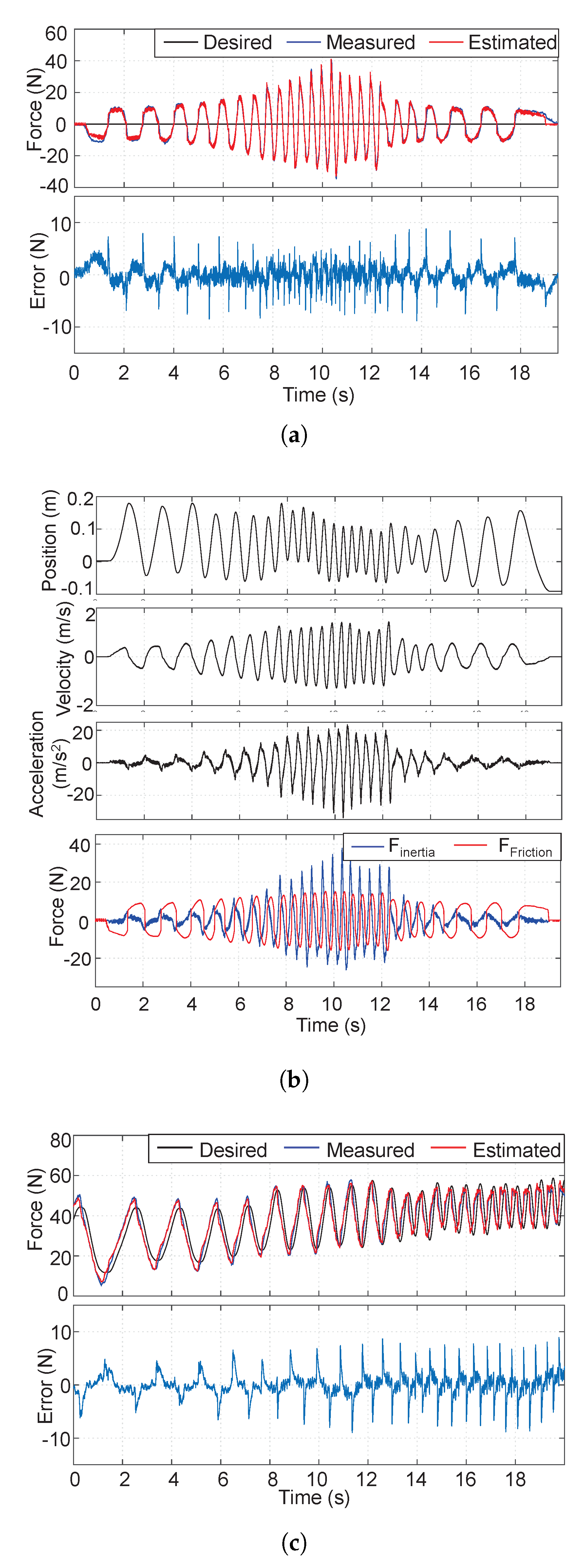
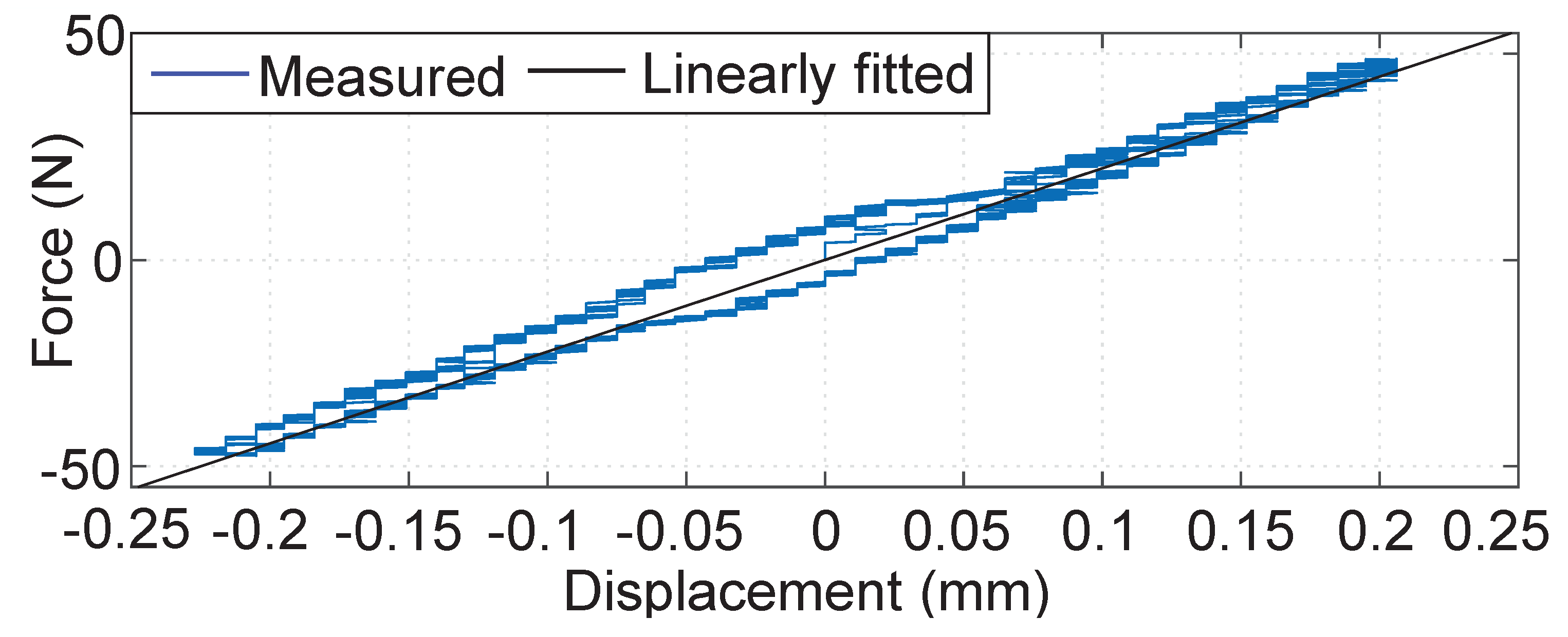
Zero current was delivered to the motor to identify the reflected inertia and the friction. A human then applied a chirp force to the linear actuator by holding a load cell mounted on the actuator end-effector; the displacement and load cell force were recorded with a sampling rate of 1 kHz. A least-square method was applied using the measured displacement and force from the load cell. Velocity and acceleration were calculated using the time-derivative of x ( t ) measured from the motor encoder and then smoothed using the moving average method. The University of Illinois at Urbana-Champaign Institutional Review Board reviewed and approved this research study, as well as the other research studies referred to in Section 4 and Section 5. Informed consent was obtained from the subject. Figure 10a shows the desired and measured forces, estimated force with the identified model, and estimation error. The root mean square (RMS) and maximum magnitude errors were 1.90 N and 9.98 N, respectively. This accurate identification was possible because the friction was included in the actuator model, unlike in [22]. The maximum error comes from static friction at zero velocity, which the Coulomb and viscous friction model cannot properly account for. More complex friction models, such as the Dahl and LuGre models, can be used to reduce this error; however, they are not employed here because this model is sufficiently accurate to describe dynamic motions at non-zero velocities and the Coulomb friction is small compared to the maximum actuator force. The identified values of the parameters were m = 1.116 kg, F C o u l o m b = 5.26 N, and a v i s c o u s = 7.52 Ns/m. The reflected inertia of the rotor and idler pulley system was estimated as 0.583 kg by subtracting the actual inertia of the rod, timing belt, and tensioner. As shown in Figure 10b, friction dominates the undesirable forces when the acceleration is small, while the inertial force dominates during high-frequency motion. The identified friction and inertial parameters indicate that the actuator is highly backdrivable and has small inertia. As discussed in Section 2, these characteristics do not greatly change even if the ROM is expanded from the current 1.1 m because the inertia of the carbon fiber rod and timing belt is small.
After identifying the parameters that determine the natural response, the motor constant was identified similarly. A soft virtual spring force with an arbitrary stiffness was applied to the actuator, and a human moved the end-effector with a chirp force. The identified motor constant was 3.25 N/A. Figure 10c shows the verification of the identified motor constant. The desired force was generated by a soft virtual spring with a stiffness of 0.4 N/mm and the actuator end-effector force was measured by the load cell. The RMS and maximum estimation errors were 2.19 and 8.96 N, respectively. Note that the actuator can generate up to 100 N [22] and requires no feedback from the load cell.
The frequency response of the linear actuator was tested to analyze the force capability in different frequencies. The end-effector was fixed to a solid frame and sinusoidal reference forces of different frequencies were commanded to the actuator. The magnitude was set to 50 N, which is half of the maximum force of the linear actuator. The results in Figure 11 show that the actuator force response had a cutoff frequency near 30 Hz and showed resonance around 100 Hz. Considering the characteristics of parallel linear actuation mechanism, the haptic interface is expected to show a similar force bandwidth if the end-effector is lightweight and the connection part is stiff enough. The longitudinal stiffness of the timing belt was identified as 222 N/mm by fitting a linear spring model to the data measured at a low frequency (1 Hz, Figure 12). Note that the actuator stiffness can be further reinforced by using a timing belt with higher longitudinal stiffness if the ROM is to be extended.
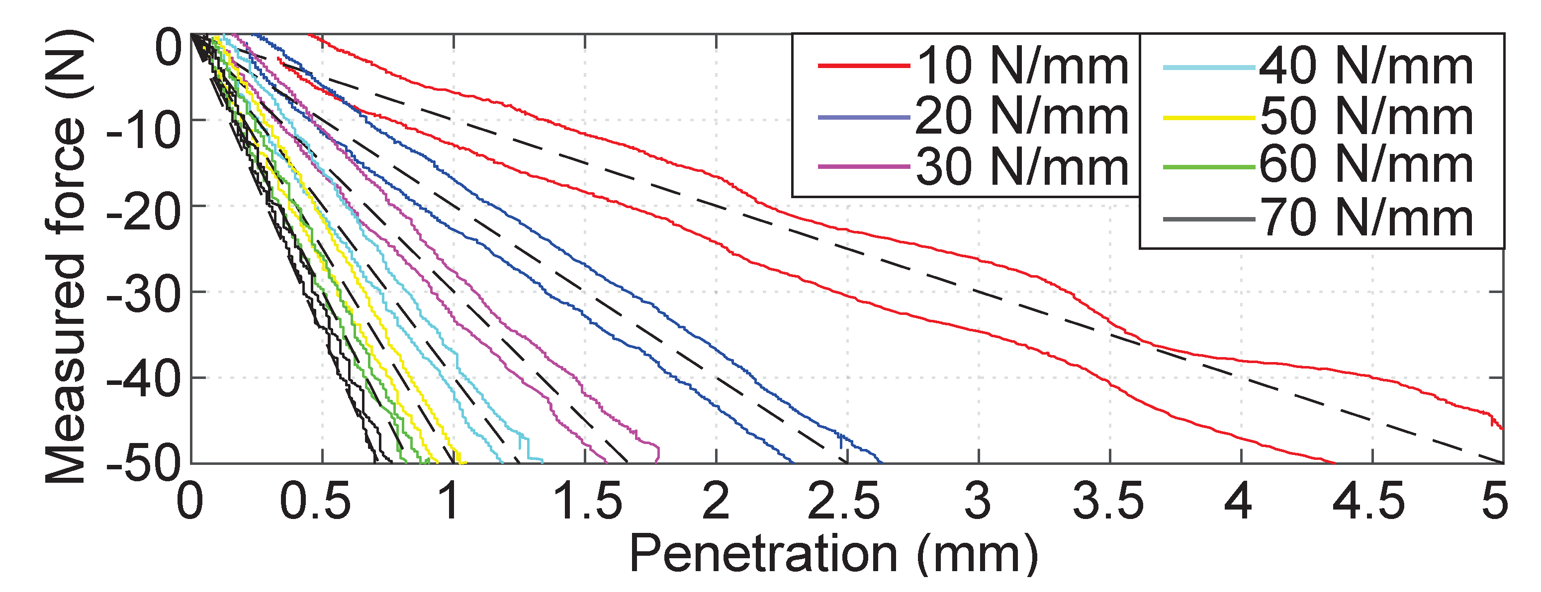
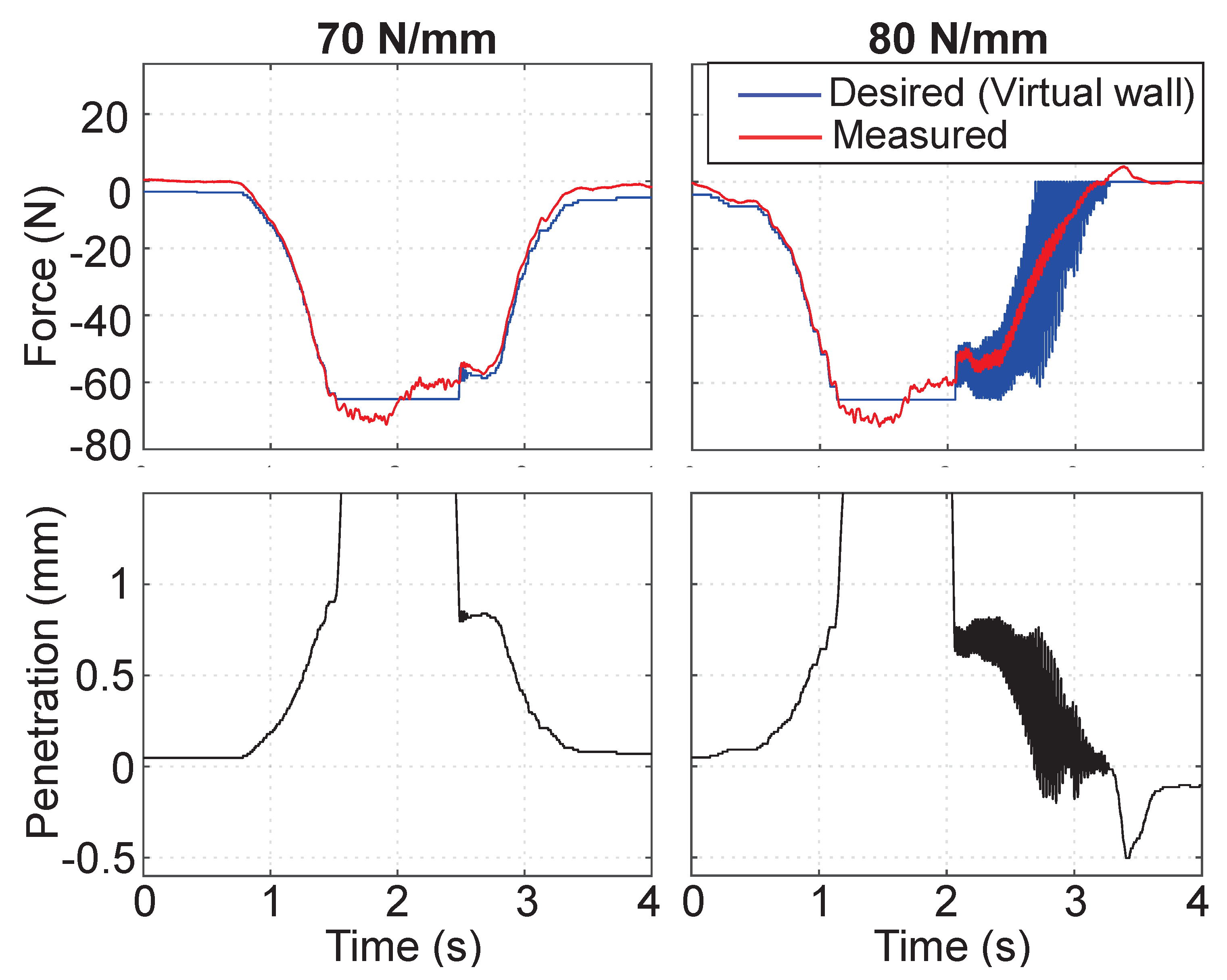
To investigate the maximum stiffness that the linear actuator can provide to the user, we conducted a stiffness rendering experiment. A human slowly pulled and released the load cell at the end of the linear actuator while rendering a virtual wall with a pure spring constant; the stiffness was varied in each trial. Figure 13 shows the experimental result. The actuator delivered a linear force feedback up to a stiffness of 70 N/mm. Rendering a virtual wall stiffer than 70 N/mm showed vibrations when the user released the actuator (Figure 14). This kind of stability issue may develop when the user-side impedance is low and the virtual stiffness is high [29]. Although the slight friction of the interface naturally dissipated energy, a stiffness of 80 N/mm resulted in instability. Despite the stability problem, small inertia is required to ensure transparency at high frequency for both impedance and admittance control [15]. The stability problem could be addressed in the sense of control, such as by applying a passivity-based controller [1]. The controller must be designed considering the stiffness of the application environment, such as the stiffness of the teleoperated robot or the virtual environment. We did not include such a controller here because this paper focuses on the design and analysis of the mechanism and the modular linear actuator. In addition, the instability due to rendering high impedance is greatly reduced in our system because it performs open-loop torque control based on the current. There is no feedback loop using a force/torque sensor. Our approach to open-loop force control has been previously demonstrated in legged robots [30,31].
However, 70 N/mm of stiffness is sufficiently high to render a stiff wall, considering that the maximum virtual stiffness of commercial haptic devices is 3 to 12 N/mm within a small ROM. As the linear actuator provides high stiffness, the perceived stiffness at the end-effector depends on the stiffness of the linkages between the actuator and end-effector, which is the gimbal handle in the proposed system. The structure size of the handle is small compared to the system’s ROM; thus, it is easy to make the stiffness high compared to the linkages of rotational mechanisms if similar cross-sectional dimensions and materials are used for the linkages. Small, lightweight, and passive end-effector designs such as those mentioned in Section 2 can ensure force capability and haptic force density calculated by the sum of forces and inertia of the actuator.

4. Experimental Results and Discussion

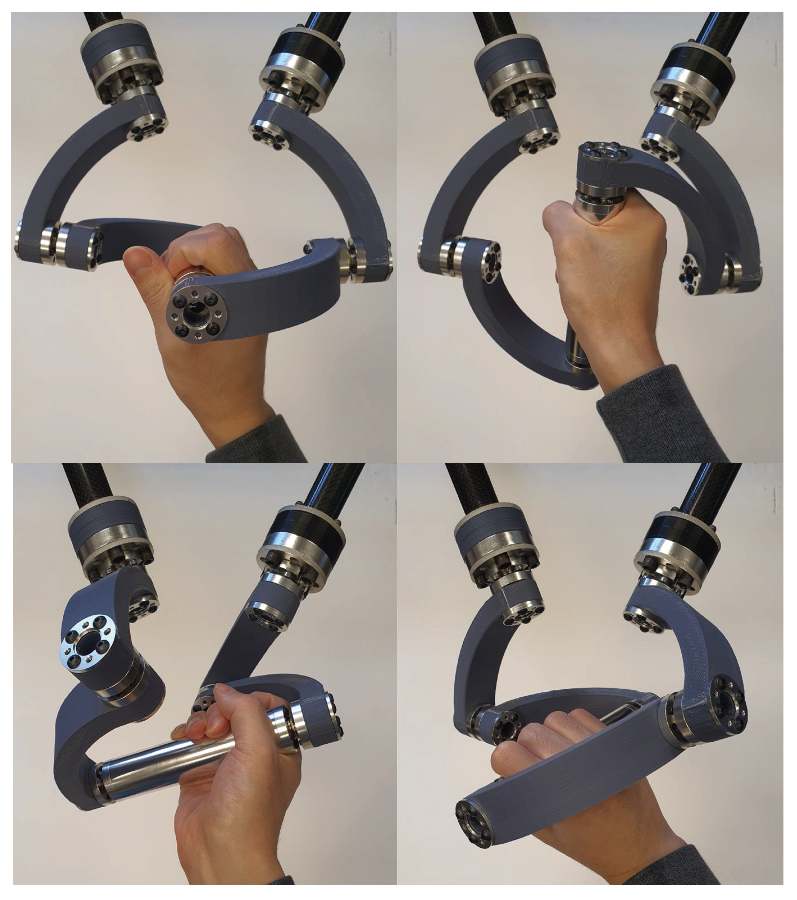
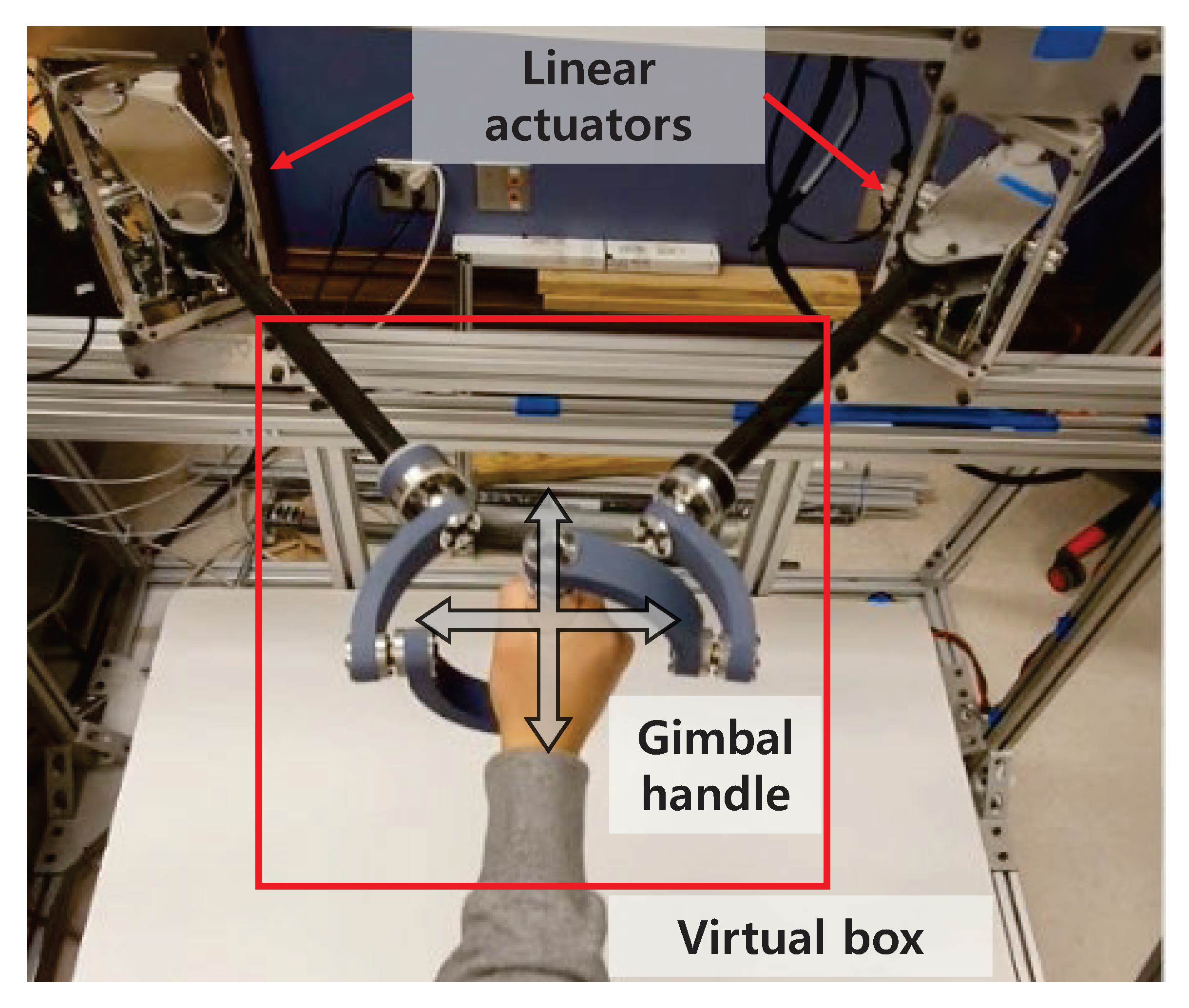
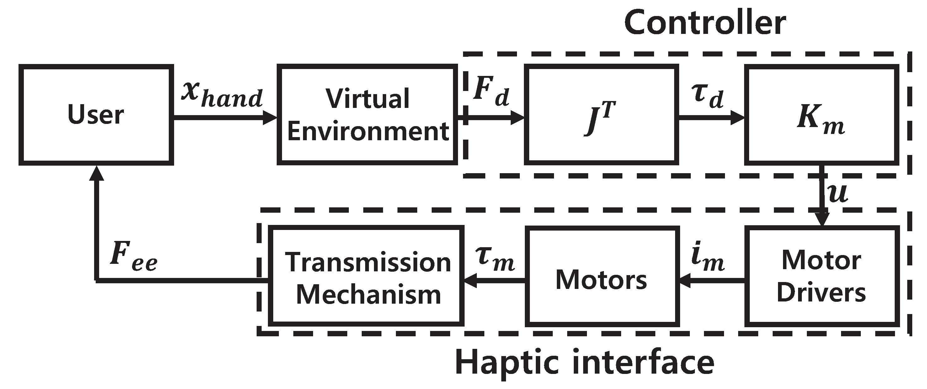
The performance of the proposed haptic interface was tested experimentally. A user rotated the gimbal handle as desired. As shown in Figure 15, the gimbal handle allowed free rotation of the user’s hand. The available ROMs were about 45 to 135 in pitch and 90 to 135 in roll. The yaw motion ranged from 60 to 60 until the user’s forearm reached to the gimbal. The force delivery of the interface was tested by rendering a virtual box; Figure 16 shows the experimental setup. A 300 mm × 300 mm 2D virtual box was created and a virtual force field with a stiffness of 2 N/mm was set to the edge. The maximum force that could be applied by an actuator was limited to 65 N, and the task-space force was limited to 100 N to ensure safety. Figure 17 shows the control diagram of the haptic interface. The end-effector force was controlled by a simple feed-forward (open-loop) controller using a Jacobian assuming quasi-static motion. The desired task space force F d was calculated as follows:
F d = k p x p
where k p is the stiffness of the virtual box and x p is the orthogonal penetration to the virtual box edge. The required joint-space torque τ d was calculated from the desired task-space force F d as follows:
τ d = J T F d
The inertia, friction, and other nonlinearities were ignored because the actuator provides high backdrivability, as shown in the system identification results. It was not necessary to consider possible collision with the user in the workspace because the actuators are extended from the front of the user.
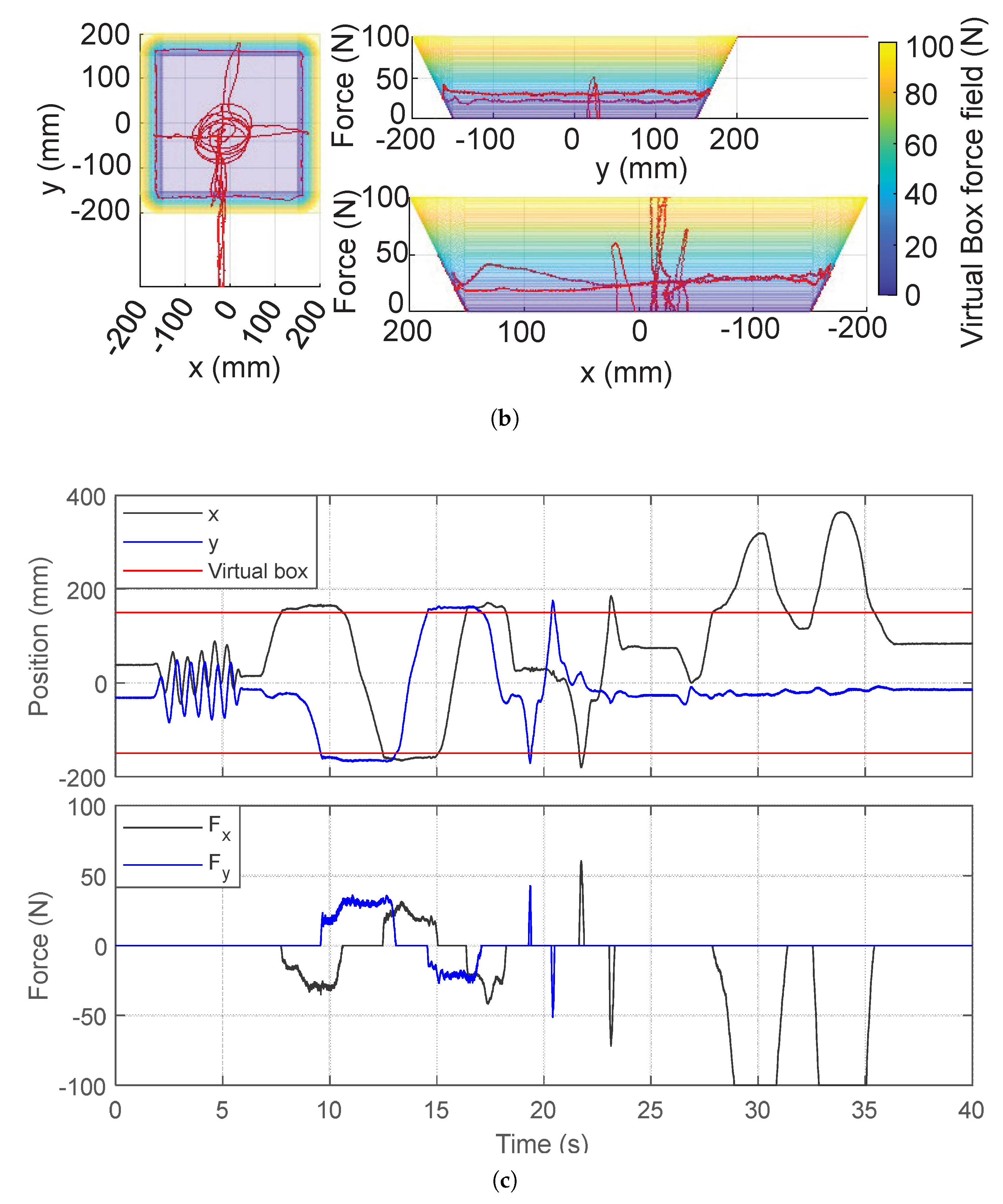
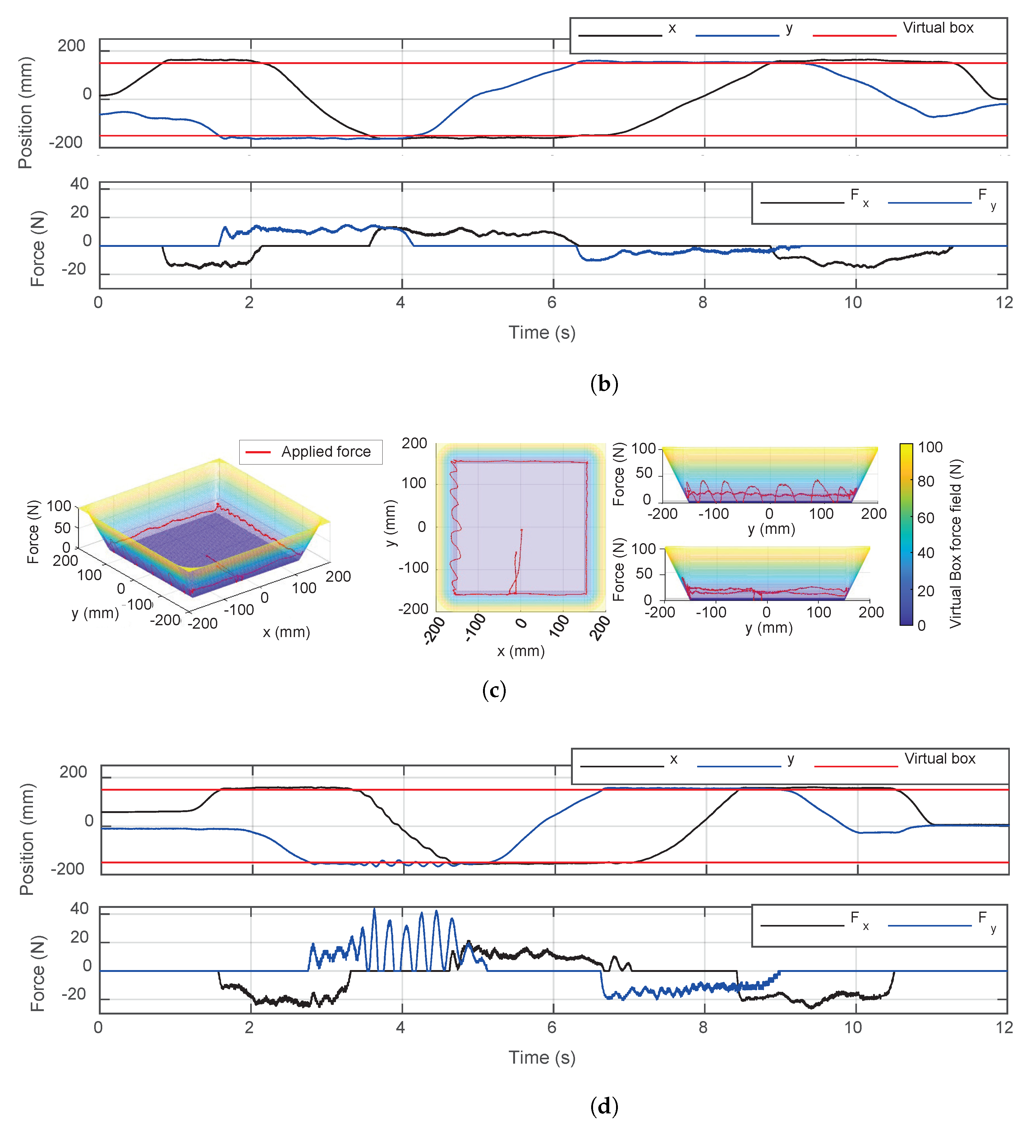
The user tested backdrivability in free space by moving the end-effector and interacted with the virtual box via force feedback. The video in https://www.youtube.com/watch?v=MEvPQ4PBzNM (accessed on 29 June 2023) shows the experiments conducted with the virtual box. As shown in the video, the user can freely rotate the hand with the DOFs of the gimbal handle. It was possible to interact with the virtual box under the guidance of the force field without inducing significant stability issues. Figure 18 shows the result of a similar experiment. The force field of the virtual box is shown as the color gradient in Figure 18a,b. The 2D end-effector trajectory and the forces applied at the points are shown as the red line. The time plot (Figure 18c) shows the result differently. The user was able to slide on the virtual surface with a contact force of near 25 N without significant effort in 7.7 s < t < 18.3 s. As the gimbal handle was fabricated from 3D printed plastic and the displayable stiffness of the haptic interface is limited by its stiffness, the available stiffness was limited to 2 N/mm. While the user could interact with the virtual environment under a lower stiffness (Figure 19a,b, k p = 1 N/mm), it was difficult to achieve natural contact under higher stiffness (Figure 19c,d, k p = 3 N/mm). The end-effector showed a bouncing motion under high stiffness; however, this could be improved if stiffer material were applied to enhance the stiffness of the entire system.

5. Conclusions

In this paper, we have presented a new haptic interface mechanism with linear actuators.
  • Force, inertia, and stiffness analyses showed that the proposed mechanism has advantages over conventional haptic interface mechanisms because of its lightweight and high-stiffness parallel structure. A 2-DOF haptic interface was evaluated as an example. Its scalability and modular design with a linear actuator enable expanding the ROM and DOFs without sacrificing performance.
  • Our experiments showed that the actuators were highly backdrivable without any feedback and can impart very high force and stiffness compared to existing devices. The timing belt transmission eliminates the need for a high-quality gearbox, resulting in reduced cost and a simplified design by changing the pulley radius. An accurate system identification was achieved with the Coulomb and viscous friction model, although it showed less accurate results near zero velocity.
  • Our analysis and experiments with the prototype haptic interface imply that the proposed mechanism can provide high force and stiffness along with a wide ROM. The proposed haptic interface mechanism allows the free rotation of human hands with the gimbal handle while providing interaction with the virtual environment.
  • A fully developed 3D haptic interface with a gimbal design is introduced in Section 2, and its application in dynamic teleoperation will be discussed in future research. More advanced friction models could be used in future works for friction compensation control.

Author Contributions

Conceptualization, J.R.; methodology, Y.J. and J.R.; software, Y.J.; validation, Y.J.; formal analysis, Y.J.; investigation, Y.J.; resources, Y.J. and J.R.; writing—original draft preparation, Y.J. and J.R.; visualization, Y.J.; supervision, J.R.; project administration, J.R.; funding acquisition, Y.J. and J.R. All authors have read and agreed to the published version of the manuscript.

Funding

This work was supported by a gift from Google and by the National Science Foundation via grant IIS-2024775. This paper was supported by research funds for newly appointed professors of Jeonbuk National University in 2022.

Data Availability Statement

All data are contained within the article.

Conflicts of Interest

The authors declare no conflict of interest.

References

  1. Hannaford, B.; Ryu, J. Time-Domain Passivity Control of Haptic Interfaces. IEEE Trans. Robot. Autom. 2002, 18, 1–10. [Google Scholar] [CrossRef]
  2. Abdossalami, A.; Sirouspour, S. Adaptive Control for Improved Transparency in Haptic Simulations. IEEE Trans. Haptics 2009, 2, 2–14. [Google Scholar] [CrossRef] [PubMed]
  3. Forbrigger, S.; Pan, Y. Improving Haptic Transparency for Uncertain Virtual Environments Using Adaptive Control and Gain-Scheduled Prediction. IEEE Trans. Haptics 2018, 11, 543–554. [Google Scholar] [CrossRef] [PubMed]
  4. Park, J.; Khatib, O. A Haptic Teleoperation Approach Based on Contact Force Control. Int. J. Robot. Res. 2006, 25, 575–591. [Google Scholar] [CrossRef] [Green Version]
  5. Lawrence, D.A. Stability and Transparency in Bilateral Teleoperation. IEEE Trans. Robot. Autom. 1993, 9, 624–637. [Google Scholar] [CrossRef] [Green Version]
  6. Sim, Y.; Ramos, J. The dynamic effect of mechanical losses of transmissions on the equation of motion of legged robots. In Proceedings of the IEEE International Conference on Robotics and Automation (ICRA), Xi’an, China, 30 May–5 June 2021; pp. 2056–2062. [Google Scholar]
  7. Hulin, T.; Hertkorn, K.; Kermer, P.; Schatzle, S.; Artigas, J.; Sagardia, M.; Zacharias, F.; Preusche, C. The dlr bimanual haptic device with optimized workspace. In Proceedings of the IEEE International Conference on Robots and Automation (ICRA), Shanghai, China, 9–13 May 2011; pp. 3441–3442. [Google Scholar]
  8. Frisoli, A.; Salsedo, F.; Bergamasco, M.; Rossi, B.; Carboncini, M.C. A Force-Feedback Exoskeleton for Upper-Limb Rehabilitation in Virtual Reality. Appl. Bionics Biomech. 2009, 6, 115–126. [Google Scholar] [CrossRef] [Green Version]
  9. Endo, T.; Kawasaki, H.; Mouri, T.; Ishigure, Y.; Shimomura, H.; Matsumura, M.; Koketsu, K. Five-fingered haptic interface robot: Hiro III. IEEE Trans. Haptics 2011, 4, 14–27. [Google Scholar] [CrossRef] [PubMed]
  10. Force Dimension. Delta.3. Available online: https://www.forcedimension.com/products/delta (accessed on 25 April 2023).
  11. Quanser. HD2 High Definition Hpatic Device. Available online: https://www.quanser.com/products/ (accessed on 25 April 2023).
  12. Cyber Glove Systems. CyberForce. Available online: http://www.cyberglovesystems.com/cyberforce (accessed on 25 April 2023).
  13. 3D Systems. Phantom Premium 1.5 HF. Available online: https://www.3dsystems.com/ (accessed on 25 April 2023).
  14. Gosselin, G.; Kong, X.; Focault, S.; Bonev, I. A fully-decoupled 3-dof translational parallel mechanism. In Proceedings of the 4th Chemnitz Parallel Kinematics Seminar Parallel Kinematic Machines in Research and Practice, Chemnitz, Germany, 20–21 April 2004; pp. 595–610. [Google Scholar]
  15. Zinn, M.; Khatib, O.; Roth, B.; Salisbury, J.K. Large Workspace Haptic Devices—A New Actuation Approach. In Proceedings of the Symposium on Haptic Interfaces for Virtual Environments and Teleoperator Systems, Reno, NV, USA, 13–14 March 2008; pp. 185–192. [Google Scholar]
  16. Perret, J.; Dominjon, L. The INCA 6D: A Commercial Stringed Haptic System Suitable for Industrial Applications. In Proceedings of the SPIDAR Anniversary Symposium, Lyon, France, 9 December 2009. [Google Scholar]
  17. Proteus Motion. Proteus Motion. Available online: https://proteusmotion.com/ (accessed on 25 April 2023).
  18. Maxwell, S. A Modulated-Energy-Dissipation Manipulator and Application to Suppressing Human Arm Tremor. Ph.D. Thesis, Massachusetts Institute of Technology, Cambridge, MA, USA, 1990. [Google Scholar]
  19. Billette, G.; Gosselin, C. Producing rigid contacts in cable-driven haptic interfaces using impact generating reels. In Proceedings of the IEEE International Conference on Robots and Automation (ICRA), Kobe, Japan, 12–17 May 2009; pp. 307–312. [Google Scholar]
  20. Lee, G.; Hur, S.; Oh, Y. High-Force Display Capability and Wide Workspace With a Novel Haptic Interface. IEEE/ASME Trans. Mechatron. 2017, 22, 138–148. [Google Scholar] [CrossRef]
  21. Barnaby, G.; Roudaut, A. Mantis: A Scalable, Lightweight and Accessible Architecture to Build Multiform Force Feedback Systems. In Proceedings of the 32nd Annual ACM Symposium on User Interface Software and Technology, New Orleans, LA, USA, 20–23 October 2019; pp. 937–948. [Google Scholar]
  22. Wang, S.; Ramos, J. Dynamic Locomotion Teleoperation of a Reduced Model of a Wheeled Humanoid Robot Using a Whole-Body Human-Machine Interface. IEEE Robot. Autom. Lett. 2022, 7, 1872–1879. [Google Scholar] [CrossRef]
  23. Wang, S.; Murphy, K.; Kenney, D.; Ramos, J. A comparison between joint space and task space mappings for dynamic teleoperation of an anthropomorphic robotic arm in reaction tests. In Proceedings of the IEEE International Conference on Robots and Automation (ICRA), Xi’an, China, 30 May–5 June 2021; pp. 2846–2852. [Google Scholar]
  24. Purushottam, A.; Jung, Y.; Murphy, K.; Baek, D.; Ramos, J. Hands-free Telelocomotion of a Wheeled Humanoid. In Proceedings of the IEEE/RSJ International Conference on Intelligent Robots and Systems (IROS), Kyoto, Japan, 23–27 October 2022; pp. 8313–8320. [Google Scholar]
  25. Rancourt, D.; Hogan, N. Dynamics of Pushing. J. Mot. Behav. 2001, 33, 351–362. [Google Scholar] [CrossRef] [PubMed]
  26. Gosselin, C.M.; Pierre, E.S.; Gagne, M. On the development of the Agile Eye. IEEE Robot. Autom. Mag. 1996, 3, 29–37. [Google Scholar] [CrossRef] [Green Version]
  27. Stewart, D. A platform with six degrees of freedom. Proc. Inst. Mech. Eng. 1965, 180, 371–386. [Google Scholar] [CrossRef]
  28. Lynch, K.M.; Park, F.C. Modern Robotics; Cambridge University Press: Cambridge, UK, 2017. [Google Scholar]
  29. Adams, R.J.; Hannaford, B. Stable haptic interaction with virtual environments. IEEE Trans. Robot. Autom. 1999, 15, 465–474. [Google Scholar] [CrossRef] [Green Version]
  30. Sim, Y.; Ramos, J. Tello Leg: The Study of Design Principles and Metrics for Dynamic Humanoid Robots. IEEE Robot. Autom. Lett. 2022, 7, 9318–9325. [Google Scholar] [CrossRef]
  31. Ramos, J.; Kim, S. Dynamic locomotion synchronization of bipedal robot and human operator via bilateral feedback teleoperation. Sci. Robot. 2019, 4, eaav4282. [Google Scholar] [CrossRef] [PubMed]
Figure 1. Dynamic teleoperation system with human–machine interface (HMI): (a) backdrivable linear actuators, (b) high-speed motion capture system, (c) force plate, and (d) teleoperated robot.
Actuators 12 00293 g001
Figure 2. The proposed planar linear haptic interface with modular actuators: (a) haptic interface and (b) modular actuator.
Actuators 12 00293 g002aActuators 12 00293 g002b
Figure 3. Detailed design of the proposed haptic interface: (a) overview of the system and (b) linear motion guidance mechanism of the actuator.
Actuators 12 00293 g003
Figure 4. A 3-DOF handle design concept. All linear actuator axes and rotational axes of the gimbal cross the center of rotation.
Actuators 12 00293 g004
Figure 5. The concept of haptic force density F r ( q , θ F r ) , provided by the device’s force capability per unit of reflected inertia for a certain direction.
Actuators 12 00293 g005
Figure 6. Force capability, inertial force, and their ratio for different haptic interface mechanisms: (a) the proposed parallel linear mechanism, (b) serial rotational mechanism, and (c) parallel rotational mechanism.
Actuators 12 00293 g006
Figure 7. Haptic force densities of the parallel linear and rotational mechanisms. The values are scaled down to 1/10.
Actuators 12 00293 g007
Figure 8. Structural stiffness of the linear parallel and rotational mechanisms.
Actuators 12 00293 g008
Figure 9. Dynamic model of the linear actuator.
Actuators 12 00293 g009
Figure 10. System identification results for the linear actuator: (a) system identification results for the inertia and friction; (b) position, velocity, and acceleration of the linear actuator and the friction and inertial force in the system identification experiment; (c) system identification results for the motor constant.
Actuators 12 00293 g010
Figure 11. Frequency response of the linear actuator with a reference force magnitude of 50 N.
Actuators 12 00293 g011
Figure 12. Timing belt stiffness identification results.
Actuators 12 00293 g012
Figure 13. Displayable stiffness of the linear actuator. The dotted lines are the desired stiffnesses and the solid lines are experimental data.
Actuators 12 00293 g013
Figure 14. Time plot of the stiffness rendering experiment.
Actuators 12 00293 g014
Figure 15. Free rotation with the gimbal handle.
Actuators 12 00293 g015
Figure 16. Experimental setup for the test involving interaction with a virtual box.
Actuators 12 00293 g016
Figure 17. Block diagram of the haptic interface control; x h a n d is the user hand position, F d and F e e are the desired and actual end-effector forces, respectively, τ d and τ m represent the desired and output motor torques, respectively, i m is the current applied to the motor, and u is the control input for the motor drivers.
Actuators 12 00293 g017
Figure 18. Virtual box rendered as a potential field, showing the position and applied force on the end-effector in the interaction with the virtual box: (a) isometric view, (b) top and side views, and (c) time plot.
Actuators 12 00293 g018aActuators 12 00293 g018b
Figure 19. Virtual box experiment results with different stiffnesses, showing the position and applied force on the end-effector in the interaction with the virtual box: (a) isometric view, top view, and side views with k p = 1 N/mm, (b) time plot with k p = 1 N/mm, (c) isometric view, top view, and side views with k p = 3 N/mm, (d) time plot with k p = 3 N/mm.
Actuators 12 00293 g019aActuators 12 00293 g019b
Table 1. Specifications of the 2-DOF haptic interface.
Specification
Min. available force83 N (Continuous)
at home position166 N (Peak)
MotorTurnigy 9235–100 KV
Pulley radius: 28.245 mm
Nominal torque: 2.825 Nm
SensorMotor encoder:
14 bit incremental
Actuator gimbal encoder:
12 bit absolute
ControllerNI cRIO-9082
Control rate: 1 kHz
FPGA clock: 40 MHz
Linear motion rodMaterial: CFRP
OD: 25.4 mm
ID: 22.86 mm
Length: 1219 mm
Weight: 158 g
Timing beltGates PowerGrip
GT3 5MGT
Glass fiber reinforced
Gimbal handleMaterial: ABS and steel
Weight: 562 g
Disclaimer/Publisher’s Note: The statements, opinions and data contained in all publications are solely those of the individual author(s) and contributor(s) and not of MDPI and/or the editor(s). MDPI and/or the editor(s) disclaim responsibility for any injury to people or property resulting from any ideas, methods, instructions or products referred to in the content.