Abstract
Strain wave gear reducers, also known as harmonic drives, are widely used in industrial robots and collaborative robots. The zero-backlash feature is very important for these applications. However, this places extremely high demands on the machining accuracy of the strain wave gear reducer. Excessive manufacturing errors will lead to excessive backlash, affecting transmission accuracy or making installation difficult, and the flexible spline (or flexspline) is prone to wear, resulting in reduced accuracy with use. This study proposes a novel strain wave gear reducer with a double flexspline structure. The original “circular spline” which was rigid will be redesigned to be slightly flexible and deformable with an additional deformation adjustment structure, which reduces the requirements for machining accuracy, and realizes the same zero-backlash characteristic of traditional structure. The experimental results show that the new strain wave gear reducer has extremely low lost motion, hysteresis loss, and high torsional rigidity. The new strain wave gear reducer provides a more economical way to realize the zero-backlash reducer and helps to solve the problem of the accuracy decline of the strain wave gear reducer due to the wear of the flexspline.
1. Introduction
Strain wave gear mechanism was invented by the American inventor Clarence Walton Musser in 1955 [1,2]. Strain wave gears are now installed in the most modern robotic applications in the world, especially in industrial robots and collaborative robots. All this is made possible by its key features [2]. Due to high reduction ratios with only three basic components and coaxial alignment, small dimensions and low weight compared to conventional gear types allow the use in compact and lightweight applications. Gears exhibit the absolute zero-backlash property, having an excellent positioning accuracy of less than one angular minute and a repeatability accuracy of only a few angular seconds.
Prior to Musser’s invention [1], efforts to achieve higher transmission accuracy in gear mechanisms were focused solely on making the mechanism more rigid. While the strain wave gearing, by contrast, was to make use of the flexibility of metal and apply elastic dynamics [3,4].
However, the zero-backlash feature of the current strain wave gear reducer depends on the tightness of the meshing between the teeth of the flexspline and the teeth of the circular spline after the elliptical deformation of the flexspline under the action of the wave generator. Once the meshing tightness is insufficient, the backlash will be large. On the contrary, they will not be able to assemble or rotate difficultly. Whether the flexspline and the rigid circular spline can be accurately mated depends on the machining precision of the machine tools. Higher precision requirements increase the production cost and limit some relatively cheap materials and processing techniques. At the same time, the flexspline, the circular spline, and the wave generator will wear to a certain extent during operation, and the wear will also cause the meshing tightness between the flexspline and the rigid circular spline to gradually decrease and the backlash of the reducer will gradually increase. We propose a novel strain wave gear type with a double flexspline structure. The original “circular spline” which was rigid will be redesigned to be slightly flexible and deformable with an additional deformation adjustment structure, which reduces the requirements for machining accuracy and realizes the same zero-backlash characteristic of traditional structure.
Since the strain wave gear has only three basic components, it is difficult to come up with new improvements. Most studies focus on the characteristic analysis of strain wave gear reducers, such as stress analysis [5,6,7,8,9,10,11], kinematic errors [12,13,14], hysteresis, and gear torsional stiffness [15,16]. There are also some studies that focus on the analysis of failure analysis [17,18], and some studies on the testing technology of strain wave gear reducers [19]. There are quite a few studies that focus on gear mesh analysis and propose new optimized tooth profiles [20,21,22,23,24,25,26]. There is also related research on the relationship between wave generator optimization and performance [27]. Article [28] proposed a new model to estimate its mechanical efficiency. A few researchers have proposed new ideas for the design of strain wave gear reducers [29,30].
The novelty design of the double flexspline strain wave gear type provides a more economical way to realize the zero-backlash reducer and helps to solve the problem of the accuracy decline of the strain wave gear reducer due to the wear of the flexspline. The results of the experiment show that the new type of gear acquires high transmission accuracy and high hysteresis property of stiffness with low precision of machining requirement.
2. Design of the Novel Strain Wave Gear Reducer
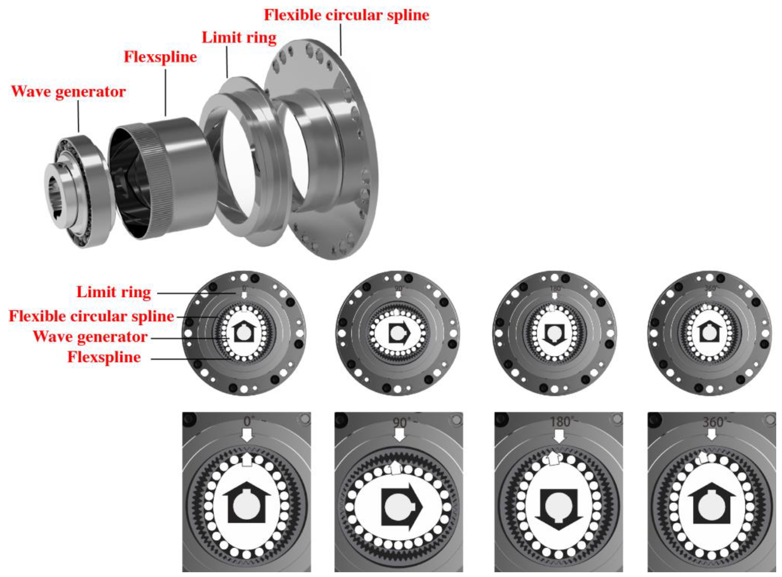
The structure and transmission process of the new strain wave gear reducer is shown in Figure 1. Its components are roughly the same as those of the general strain wave gear reducer. It still includes three basic components: a wave generator, flexspline, and a circular spline (the flexible circular spline replaces the original rigid circular spline). Furthermore, a limit ring is provided additionally.

Figure 1.
The structure and transmission process of the new strain wave gear reducer.
The wave generator has nothing to change, an elliptical steel disc at the center of the gear. It has an elliptical flexible ball bearing. The wave generator uses the flexible ball bearing to deform the flexspline, a deformable cylindrical steel sleeve with teeth arranged radially around the outside. As a deformable cylindrical outer ring, it is the flexible circular spline, which is the third component surrounding both the wave generator and flexspline, and is equipped with internal teeth.
As the wave generator rotates, the major axis and the gear meshing area shift. The number of the external teeth of the flexspline have exactly 2 teeth less than the internal teeth of the flexible circular Spline. Accordingly, during a half rotation of the elliptical wave generator, there is a relative movement of one tooth between the flexspline and the flexible circular spline; during a full rotation, there are already two teeth.
The elastic deformation of the flexible circular spline is restricted by the limit ring.
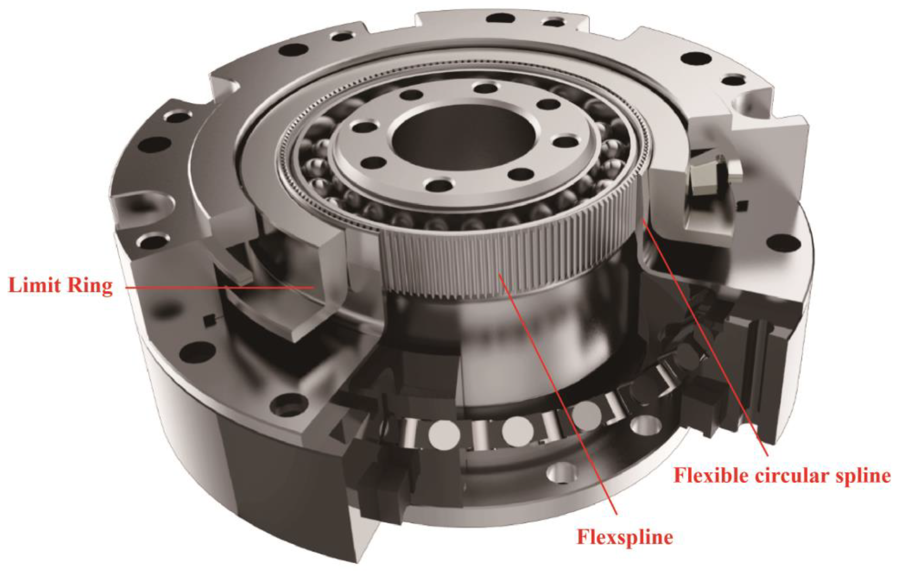
Figure 2 and Figure 3 shows the installation relationship of each component of the new strain wave gear reducer, especially the structure of the limit ring.
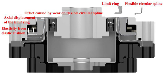
Figure 2.
The installation relationship of each component of the new strain wave gear reducer.
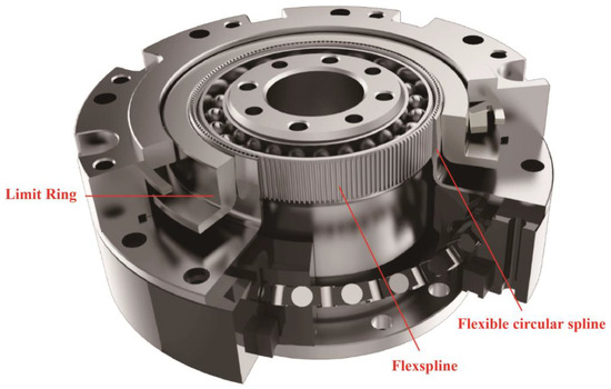
Figure 3.
New strain wave gear reducer in perspective view with partially sectioned.
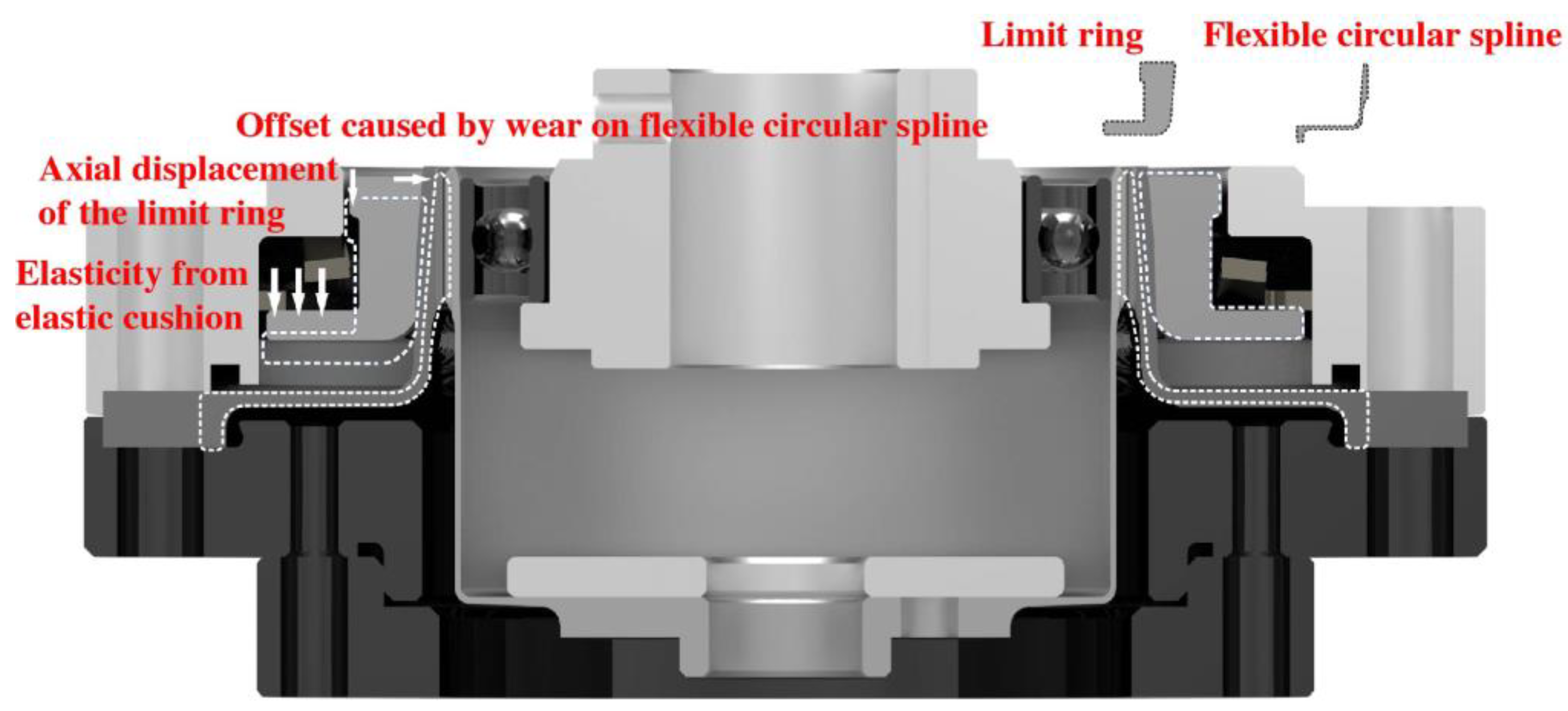
The wave generator causes the flexspline to undergo elliptical elastic deformation and meshes with the flexible circular spline part. The contact part of the flexible circular spline and the flexspline are subjected to the radial pressure of the flexspline to produce elliptical elastic deformation. The flexible circular spline is deformable, but under the same pressure, it has smaller deformation than the flexspline. The non-toothed side of the flexible circular spline is processed with a tapered contact surface. The deformable limit ring is relatively fixed with the flexible circular spline, and it is processed with an annular limit surface. The limiting contact surface of the flexible circular spline is in contact with the annular limiting surface of the limit ring. The amount of deformation of the flexible circular spline is limited by the adjustment of the limit ring.
While the strain wave gear reducer is running, the flexible circular spline is allowed to have a small or slight amount of elliptical elastic deformation along with the flexspline. This not only can allow higher machining tolerance but also improves the wear resistance of the gear reducer to prolong the precision life, so it also allows the use of cheaper materials and processing technology to produce a better manufacturing accuracy strain wave gear reducer, thus greatly reducing the cost of the strain wave gear reducer.
3. Stress Analysis of the Strain Wave Gear Reducer
In this section, the stress simulation results of the given structure are shown to illustrate the reliability of the structure. Overall simulation analysis was based on H2F-14-80 series reducers. The model includes the following components: 1. Wave generator bearing; 2. Flexspline; 3. Flexible circular spline; 4. Limit ring. The analysis process can be divided into three analysis steps: (a) the assembly of the wave generator, the flexspline, and the flexible circular spline, so that the wave generator bearing, the flexspline, and the flexible circular spline produce initial deformation; (b) the preload is applied to the limit ring (elastic pad elasticity), preload the assembly; (c) apply external loads. Analyze the stress condition of the reducer and calculate its performance parameters through post-processing.
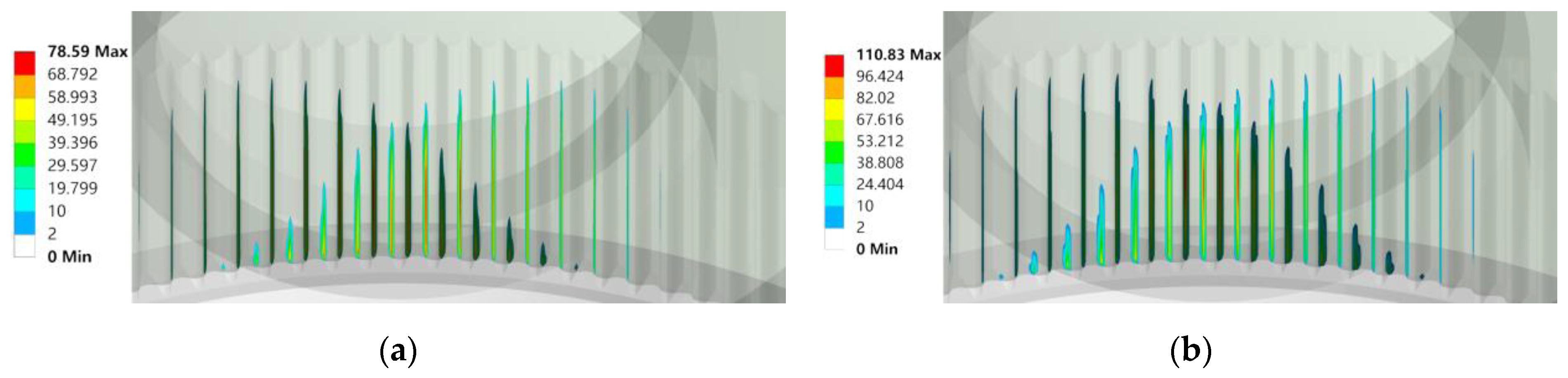
As shown in Figure 4, the limit ring will affect the contact state of the tooth surface of the flexspline and the magnitude of the contact stress. After the limit ring is assembled, the total length of the contact line on the tooth surface increases significantly, and the amplitude of the contact stress increases by 32 MPa. The limit ring makes the tooth surface contact more fully by tightening the flexible circular spline.

Figure 4.
The contact stress of the tooth surface before and after the assembly of the limit ring: (a) Before assembly; (b) After assembly.
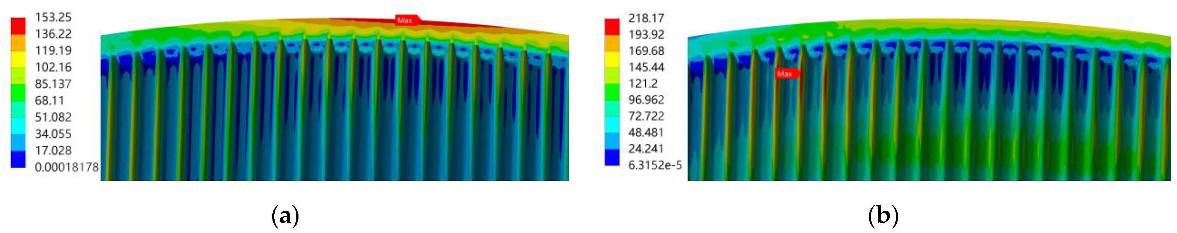
As shown in Figure 5 and Figure 6, the assembly of the limit ring will affect the equivalent stress distribution and amplitude of the flexspline and flexible circular splines. The equivalent stress of the flexspline is concentrated on the upper part. Since the limit ring restricts the deformation of the flexible circular spline in the direction of the long axis, the location of the maximum bending stress point changes. From the outer edge of the flexible circular spline to the root of the tooth, the stress of the flexible circular spline varies slightly more than that of the flexspline.
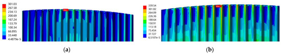
Figure 5.
The equivalent stress of the flexspline before and after the limit ring is assembled: (a) Before assembly (304 MPa); (b) After assembly (339 MPa).

Figure 6.
Equivalent stress of the flexible circular spline before and after assembly of limit ring: (a) Before assembly (153 MPa); (b) After assembly (218 MPa).
As shown in Figure 7 and Figure 8, under the torque loading working condition, the location of the maximum equivalent stress moves to the dedendum area where its allowable load is mostly affected. However, the simulation results illustrate that the limit ring does not induce much additional stress on the flexspline dedendum, and the equivalent stress on the flexible circular spline under the maximum torque is also significantly less than the yield strength limit.
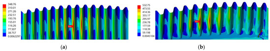
Figure 7.
Flexspline dedendum stress: (a) Dedendum stress under rated load (10 Nm); (b) Dedendum stress under instantaneous maximum torque (61 Nm).
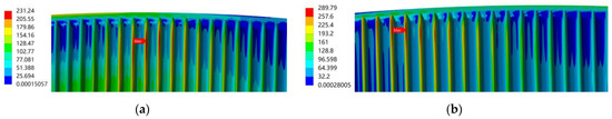
Figure 8.
Flexible circular spline dedendum stress: (a) Dedendum stress under rated load (10 Nm); (b) Dedendum stress under instantaneous maximum torque (61 Nm).
4. Analysis of the Flexspline Deformation under the Influence of the Limit Ring
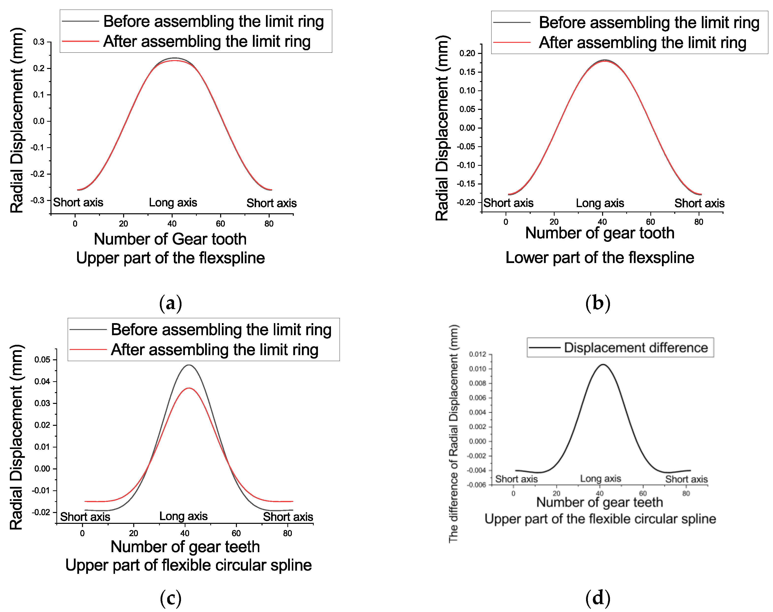
In this section, the analysis results of the influence of the limit ring on the deformation of the flexspline are attached. Taking the centroid of the reducer as the coordinate origin, a cylindrical coordinate system is established, and the post-processing outputs the radial displacement, tangential displacement, and axial displacement of each flexspline at different positions along the circumferential direction, as shown in Figure 9, Figure 10 and Figure 11. The limiting ring restricts the deformation of the flexspline, so that the teeth are fully meshed and ensures the meshing rigidity. Compared with the non-limiting ring structure, the backlash is more optimally suppressed.

Figure 9.
Radial displacement of the flexspline before and after the limit ring is assembled (a) the upper part of the inner flexspline; (b) the lower part of the inner flexspline; (c) the upper part of the outer flexible circular spline; (d) the upper part of the outer flexible circular spline.
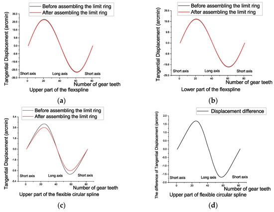
Figure 10.
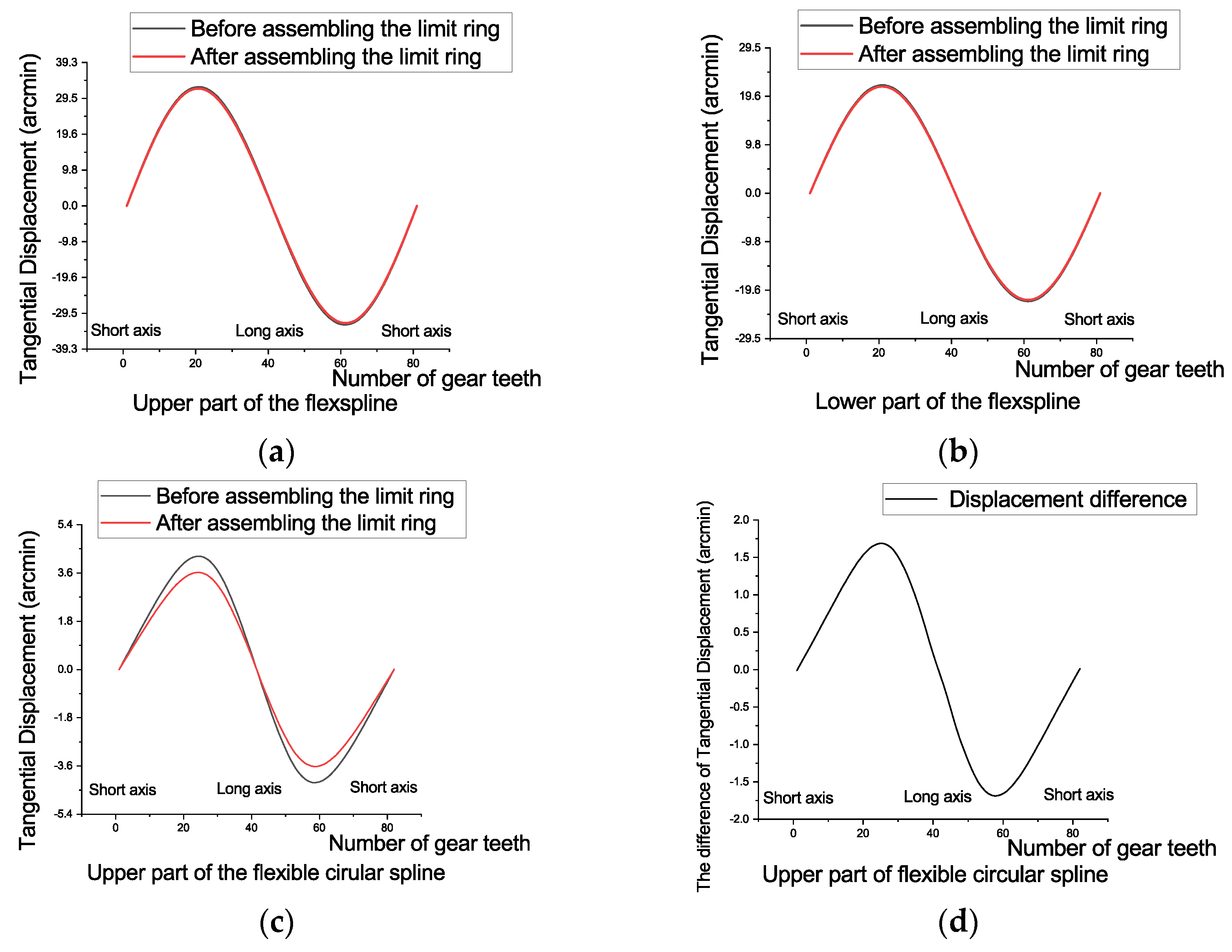
Tangential displacement of the flexspline before and after the limit ring is assembled (a) the upper part of the inner flexspline; (b) the lower part of the inner flexspline; (c) the upper part of the outer flexible circular spline; (d) the upper part of the outer flexible circular spline.
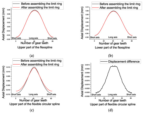
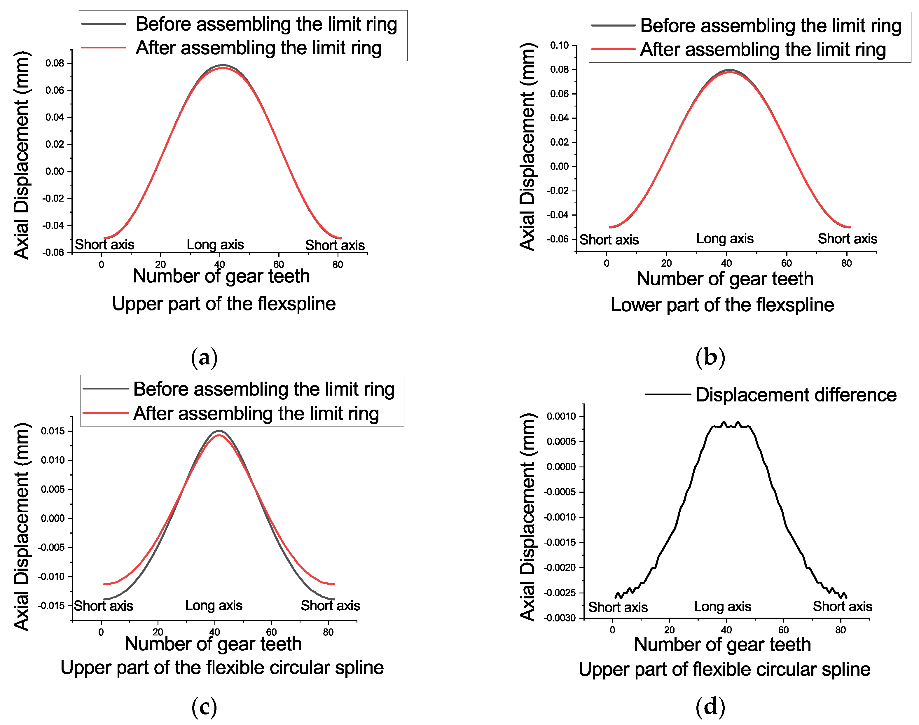
Figure 11.
The axial displacement of the flexspline before and after the limit ring is assembled (a) the upper part of the inner flexspline; (b) the lower part of the inner flexspline; (c) the upper part of the outer flexible circular spline; (d) the upper part of the outer flexible circular spline.
The limit ring makes the radial deformation of the upper major axis of the inner flexspline smaller but has little effect on the deformation of the lower part of the inner flexspline; the limit ring constrains the deformation of the outer spline more significantly. The maximum rate of change is between 16–24% of the radial and tangential displacement amplitudes. The simulation results show that the limit ring mainly realizes the backlash control by suppressing the deformation of the outer flexible circular spline and makes the meshing state of the teeth tighter than the lack of the limit ring.
5. Experiment Test of the Strain Wave Gearbox
5.1. Test Equipment and Samples
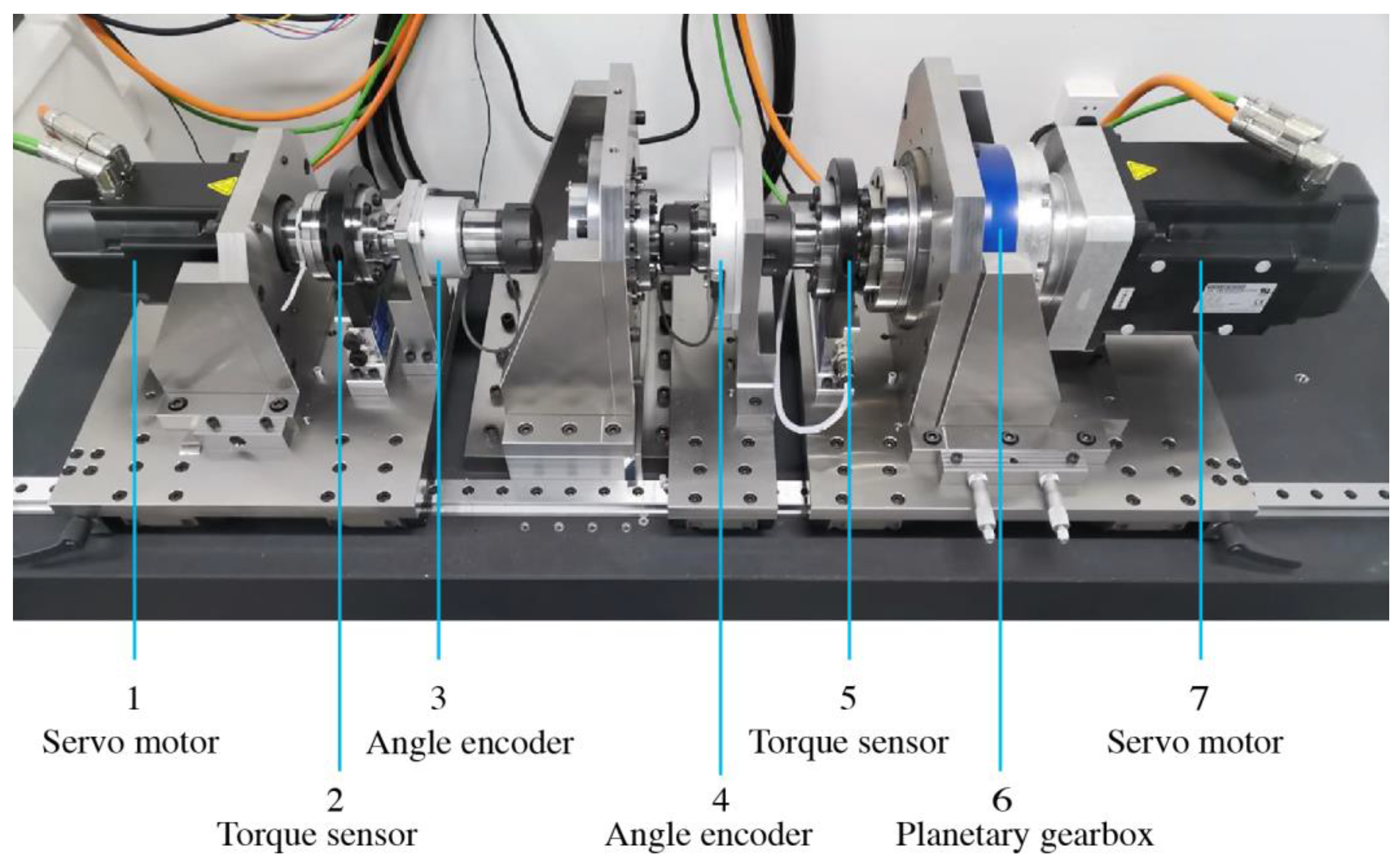
As shown in Figure 12 and Table 1, the input and output ends of the reducer to be tested are, respectively, connected to high-precision grating angle encoders, which can accurately obtain the absolute angle information of the input and output of the reducer, by calculating the difference between the actual output angle and the theoretical output angle. The outer sides of the two angle encoders are high-precision torque sensors that measure the torque at the input and output ends. The torque sensors can be used to measure parameters such as transmission efficiency, starting torque, torsional stiffness, and hysteresis characteristics. In this paper, the torque sensor only performs torsion testing of the stiffness and hysteresis characteristics. Finally, the two ends of the test bench are the input motor which provides the input speed and the output motor which provides the simulated load. As it is difficult for a single motor to provide a high enough torque, the load motor is also connected to a precision planetary gearbox.
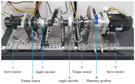
Figure 12.
Performance test system.

Table 1.
Key equipment and measurement parameters of the performance test system.
As shown in Figure 13 and Table 2, a simple test setup for testing repeat positioning accuracy was set up. The motor is directly connected to the tested reducer, which drives the connecting rod of a certain length of the simulated single-arm robot to reciprocate. The end of the mechanical arm is constantly in contact with the high-precision displacement sensor, so as to measure the repeatability of the reducer.
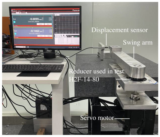
Figure 13.
Horizontal swing arm for repeat positioning accuracy test.
Table 2.
Repeat positioning accuracy test bench core device parameter table.
In this paper, 5 H2F-14-80 reducers are tested as shown in Figure 14. The reducer test samples for this research are shown in Figure 5. These design parameters are listed in Table 3. The test environment for precision is at a room temperature of 24 °C and a relative humidity of less than 70%.
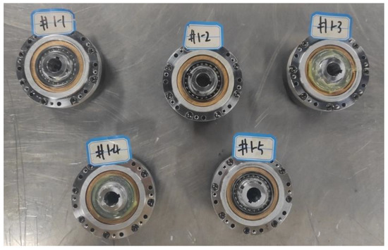
Figure 14.
Reducer samples.
Table 3.
Reducer-rated design parameters.
5.2. Test Method for Stiffness Hysteresis
Fix the input of the reducer, gradually load the output side to 80% of the rated torque and then unload it, and then gradually load it in the reverse direction to the rated torque and then unload it, recording the corresponding torque and rotation angle value of the output side. The number of samples for forward and reverse loading should be greater than 100 points, and the torque-rotation angle curve is drawn as the stiffness hysteresis curve.
Calculate the torsional stiffness, lost motion, and hysteresis of the reducer from the stiffness hysteresis curve data:
- (1)
- The torsional stiffness value is fitted according to the hysteresis curve in sections, and the unidirectional loading and unloading curves can be divided into 3 sections according to the slope. Perform the least squares linear fitting for each section of the loading and unloading data sets, and obtain the slope K = a/b (a is the angle difference, b is the torque difference) of this section, and the reciprocal of the K value is the torsional stiffness within the torque range of this section, that is, K1, K2, and K3.
- (2)
- According to the methods commonly used in the industrial field, on the hysteresis curve, when the abscissa is ±3% of the rated torque, the difference between the average values θ1 and θ2 of the 2 rotation angles corresponding to the forward and reverse curves is the geometric lost motion of the test piece. This takes into account factors such as internal friction, oil film resistance, backlash, and bearing clearance in the transmission chain. As the strain wave gear has almost zero backlash, the lost motion is used as a reference for gear accuracy.
- (3)
- When the torsional torque is gradually applied to the gear output shaft until it reaches 80% of the rated torque in one direction, the torsional angle becomes smaller as the torque is reduced. However, the torsion angle never reaches zero, even when the torsional torque is completely returned to zero. On the hysteresis curve, when the torque is 0, the torsional angle has a small amount that is not 0, and this amount is called the hysteresis loss.
5.3. Test Method for Transmission Accuracy
Transmission accuracy refers to the difference between the actual rotation angle of the output end and the theoretical rotation angle when the reducer is running stably. During the test, the reducer is driven to run stably, and the real-time rotation angle values of the input and output ends are recorded within the range of continuous operation of the output end for one circle. Take the output angle as the abscissa, and the transmission error corresponding to the angle as the ordinate, draw the transmission error curve, and the maximum value of the error change on the curve is the transmission error of the tested gear reducer.
The input speed of the reducer is set to 400 RPM (Revolutions Per Minute).
5.4. Test Method for Repeat Positioning Accuracy
The working condition of the tested gear reducer is set as the input-output axis is vertical, with a horizontal rotating load. The load arm is 4 kg and the measuring point at the end is 420 mm from the axis of the reducer. Under this working condition, continuously test the fixed point drift of the output load end of the reducer.
6. Results
6.1. Stiffness Hysteresis Test Results
6.1.1. Stiffness Hysteresis Test Curves
After the assembly, five tested reducer samples are installed in the performance test system. And they are tested with the stiffness hysteresis method. Data collected in these experiments are analyzed and compared.
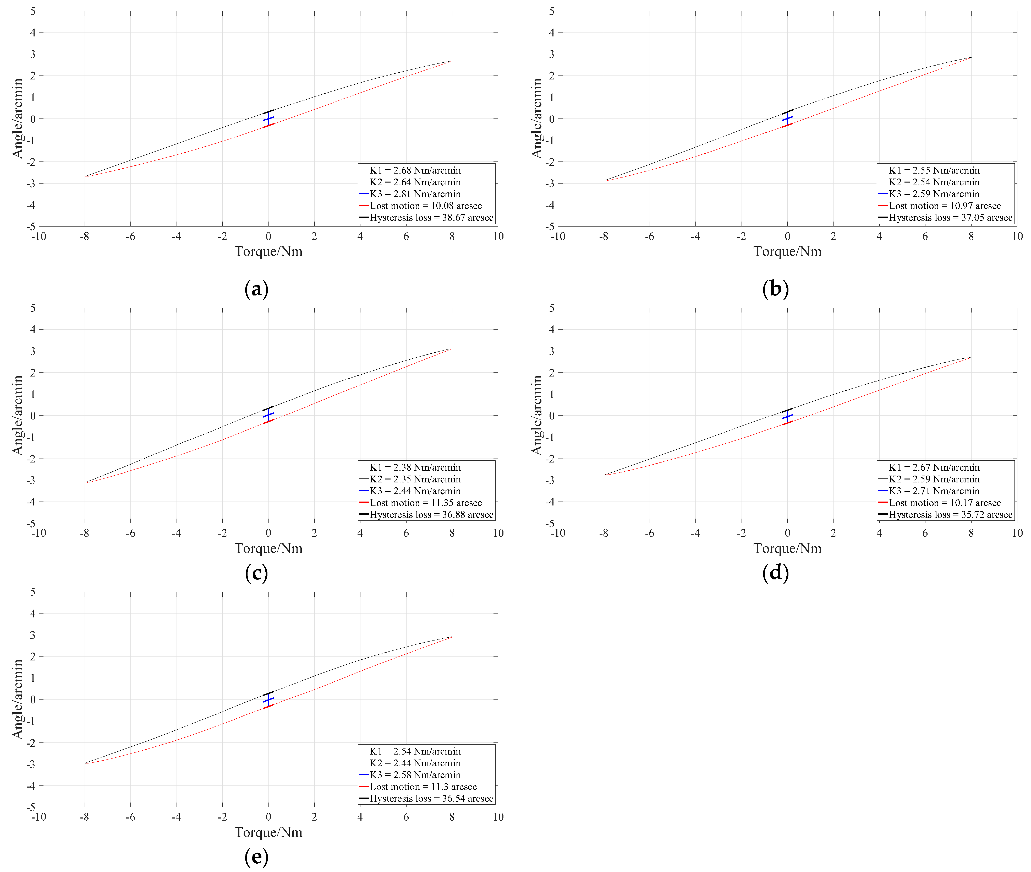
The stiffness hysteresis curves of the 5 tested reducers are shown in Figure 15, and the detailed data obtained from these curves are shown in Table 4.
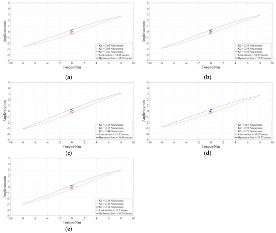
Figure 15.
Stiffness hysteresis curves under rated load (10 Nm): (a) Stiffness hysteresis curve of #1-1; (b) Stiffness hysteresis curve of #1-2; (c) Stiffness hysteresis curve of #1-3; (d) Stiffness hysteresis curve of #1-4; (e) Stiffness hysteresis curve of #1-5.
Table 4.
Torsional stiffness, lost motion, and hysteresis loss data under rated load (10 Nm).
From the data in Table 4, we can find that the tested reducers maintain high rigidity throughout the entire torque range. Lost motion keeps low values below 12 arcsec. Torsional rigidity, lost motion, and hysteresis loss are all superior to traditional strain wave gear reducers (as shown in the data in Table 5) [31].
Table 5.
Torsional stiffness, lost motion, and hysteresis loss data of conventional type reducer.
6.1.2. Influence of the Limit Ring on Stiffness Hysteresis Character
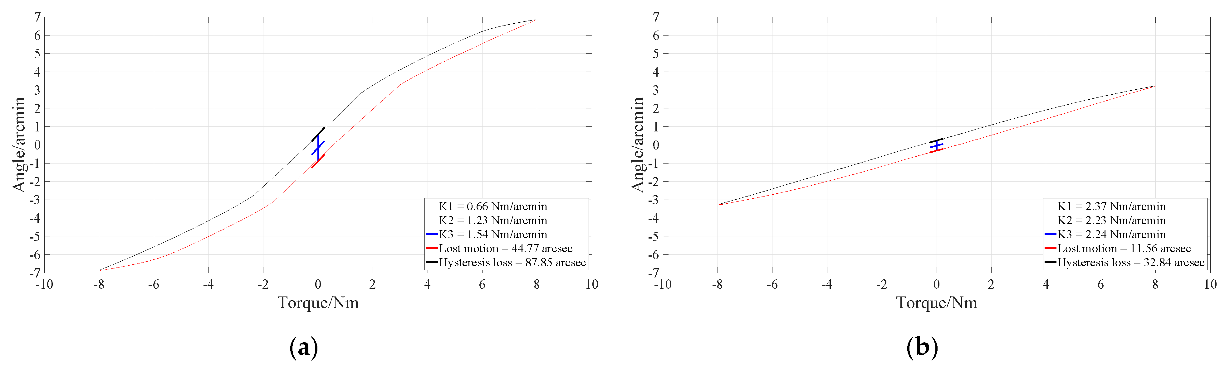
As the stiffness hysteresis curves illustrate in Figure 16 and Table 6, the limit ring plays an important role in double flexible spline strain wave gear reducer. The vital indexes, torsional stiffness, lost motion, and hysteresis loss are disappointing without installing a limit ring. However, it reaches terrific performance once the limit ring has been installed. It is because this strain wave structure requires big unidirectional stiffness on the flexible circular spline, which controls its elliptic deformation and ensures teeth are meshing completely. Flexible circular spline is easily deformed toward the inside as the limit ring does not restrict it at the inside. Unidirectional rigidity ensures tooth meshing along circular boundary conditions and its deformability to refill backlash caused by wear.
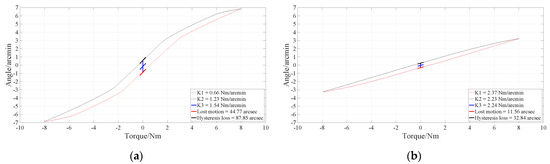
Figure 16.
Influence of Limit Ring on Stiffness Hysteresis Curve: (a) Stiffness hysteresis curve without limit ring installed; (b) Stiffness hysteresis curve with limit ring installed.
Table 6.
Torsional stiffness, lost motion, and hysteresis loss data with the influence of the limit ring.
6.2. Transmission Accuracy Test Results
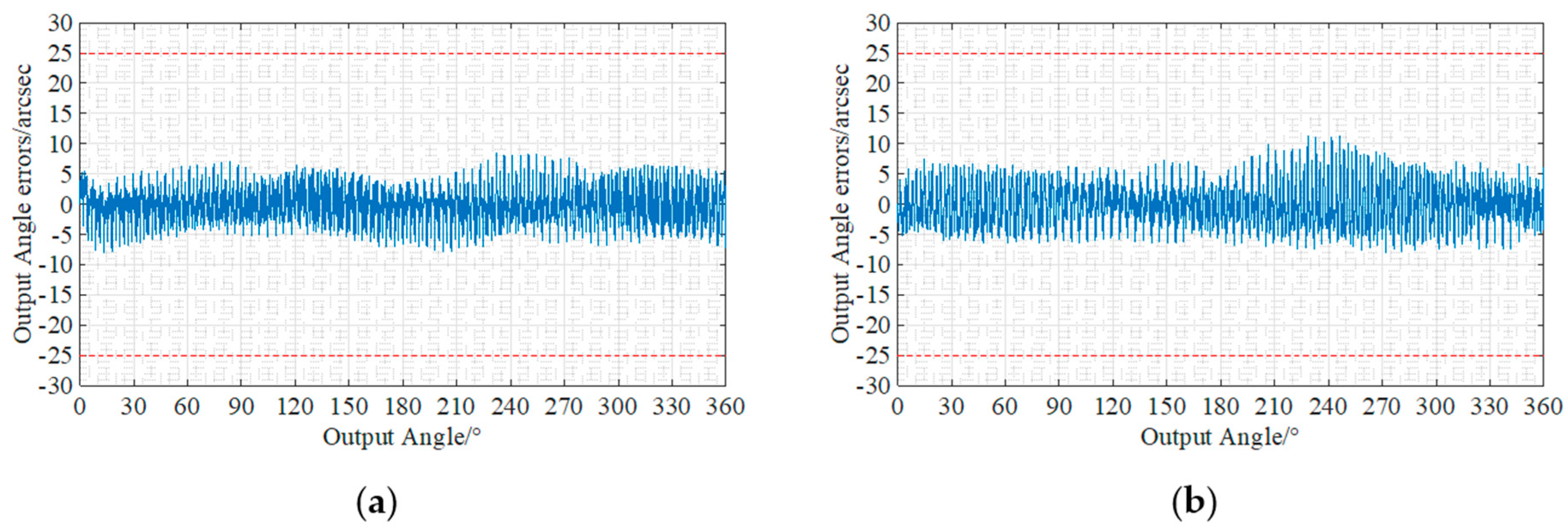
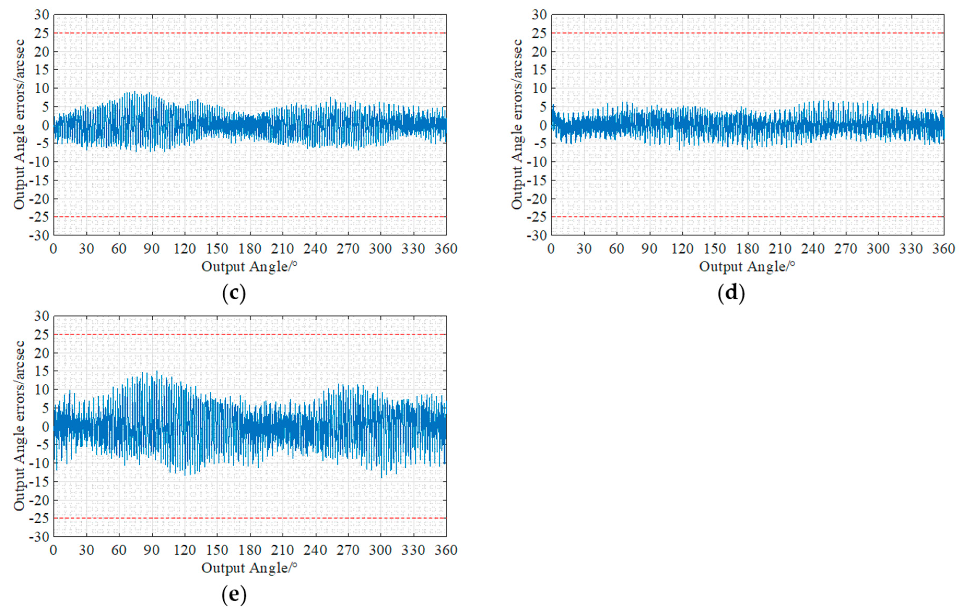
The transmission error curve of the test sample is shown in Figure 17 and Table 7. Transmission accuracy keeps low values below 20 arcsec.
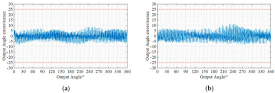

Figure 17.
Transmission error curves: (a) Transmission error curve of #1-1; (b) Transmission error curve of #1-2; (c) Transmission error curve of #1-3; (d) Transmission error curve of #1-4; (e) Transmission error curve of #1-5.
Table 7.
Transmission error test data.
6.3. Repeat Positioning Accuracy Test Results
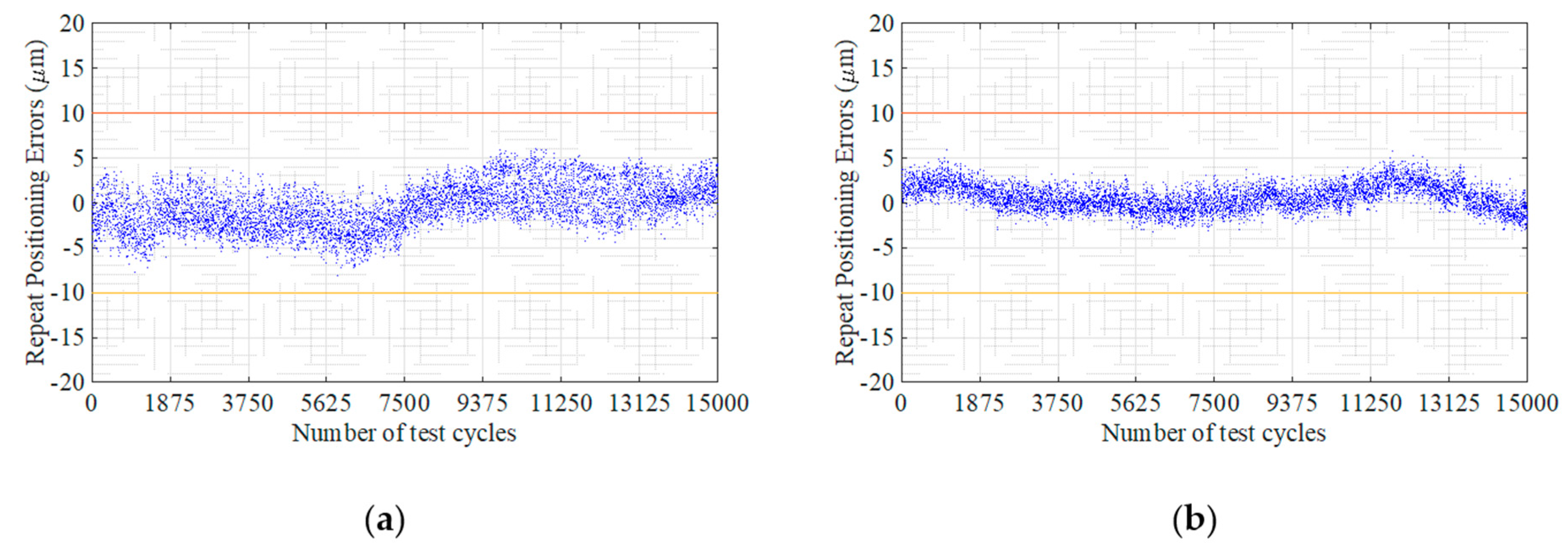
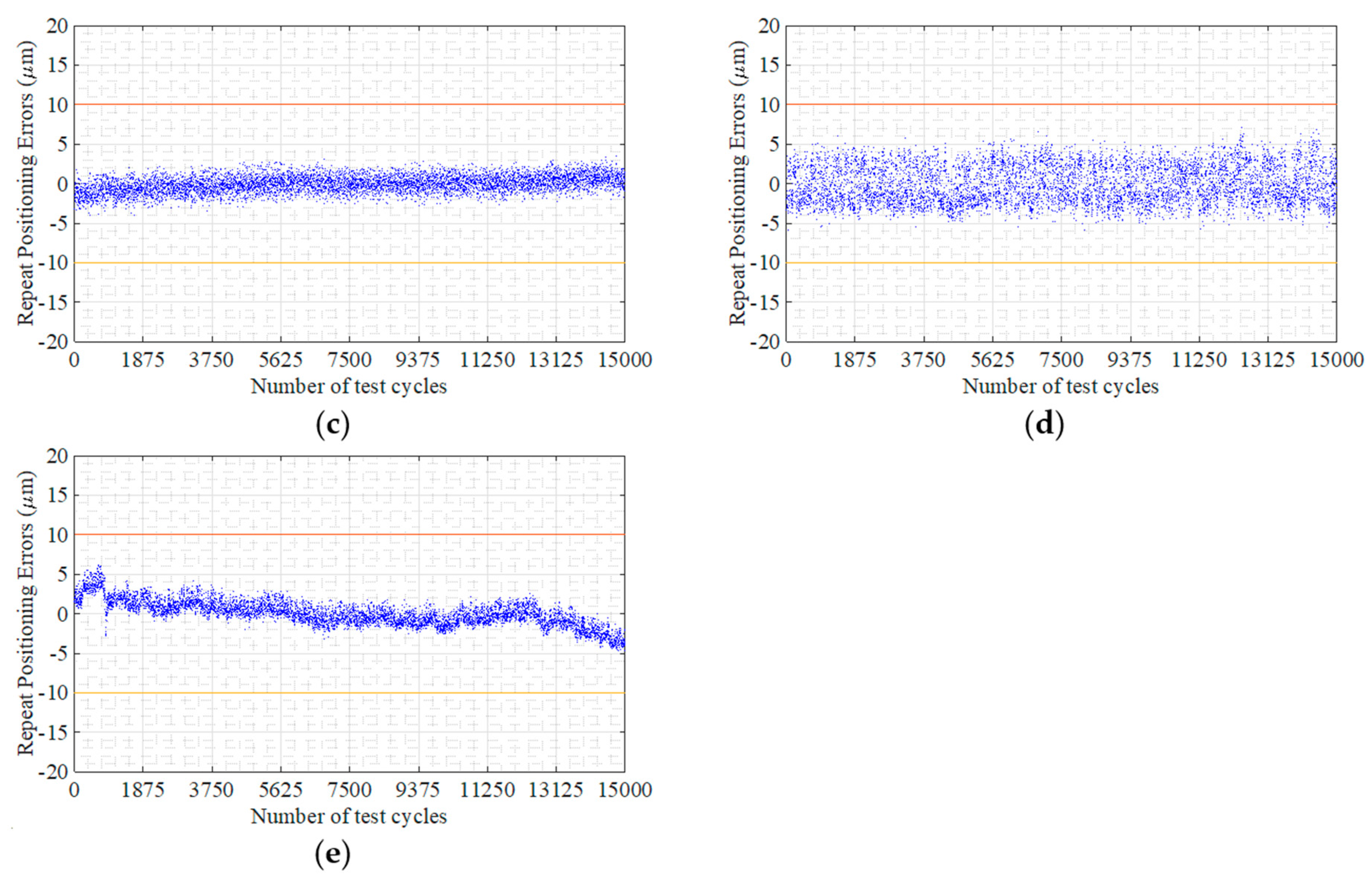
The repeated positioning drift of the measuring points at the end of the swinging arm is drawn as a scatter diagram, as shown in Figure 18.
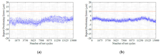
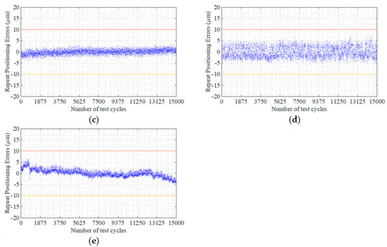
Figure 18.
Repeat positioning errors: (a) Repeat positioning errors of #1-1; (b) Repeat positioning errors of #1-2; (c) Repeat positioning errors of #1-3; (d) Repeat positioning errors of #1-4; (e) Repeat positioning errors of #1-5.
It can be seen from the test data that the repeat positioning accuracy of the H2F-14-80 reducer varies within ±0.01 mm (The red lines in Figure 8 are ±0.01 mm indicator lines.), and the value converted to the output repeat positioning angle by using geometric trigonometric relationships is ±4.9 arcsec.
7. Discussion
From the analysis in Section 3 and Section 4, we can see that the new strain wave gear reducer is conducive to the participation of more tooth surfaces in meshing after the assembly of the limit ring, which is conducive to improving the overall torsional stiffness and maintaining the zero-backlash feature. The impact of manufacturing errors on the final transmission accuracy of the product is reduced. It is also very convenient to fine-tune the limit ring to maintain high accuracy.
From the experimental results in Section 6, we can see that the new strain wave gear reducer has high torsional stiffness, extremely low lost motion, and hysteresis loss. The adjustment of the limit ring has a positive impression on the stiffness characteristics of the gear reducer.
The new strain wave gear reducer will provide a more economical way to realize the zero-backlash reducer and helps to solve the problem of the accuracy decline of the strain wave gear reducer due to the wear of the flexspline.
8. Patents
Zilong, Ling. Double-flexspline harmonic reducer with limitable deformation. U.S. Patent No. 11,614,153. 28 March 2023.
Author Contributions
Conceptualization, Z.L.; methodology, Z.L.; software, C.M.; validation, Z.L.; formal analysis, Z.L.; investigation, D.X.; resources, Z.L.; writing—original draft preparation, G.L.; writing—review and editing, K.H., Z.L. and D.X.; visualization, L.Z. and Y.Z.; supervision, K.H.; project administration, Z.L. All authors have read and agreed to the published version of the manuscript.
Funding
This research received no external funding.
Institutional Review Board Statement
Not applicable.
Informed Consent Statement
Not applicable.
Data Availability Statement
The data that support the findings of this study are available from the corresponding author upon reasonable request.
Acknowledgments
The authors would like to acknowledge Xiaofeng Xia, Siyuan Xi, Qiangfei Zhu, Zhibei Chen, Yue Li, Shanwei Liao, and Wenliang Zhao for the technical support provided during the research campaign.
Conflicts of Interest
The authors declare no conflict of interest.
References
- Walton, M.C. Strain Wave Gearing. U.S. Patent 2,906,143, 29 September 1959. [Google Scholar]
- The Secret of the Strain Wave Gear. Available online: https://newdrive.harmonicdrive.de/en/home/edition-one/the-secret-of-the-strain-wave-gear (accessed on 20 April 2023).
- Musser, C.W.; the Father of the HarmonicDrive®. Available online: https://www.hds.co.jp/english/development/hd_skill/c_w_musser/ (accessed on 20 April 2023).
- Timofeev, G.; Egorova, O.; Samoilova, M. Harmonic drive. Evolution of wave gear design. In Proceedings of the 14th IFToMM World Congress, Taipei, Taiwan, 25–30 October 2015; pp. 344–353. [Google Scholar] [CrossRef]
- Yague-Spaude, E.; Gonzalez-Perez, I.; Fuentes-Aznar, A. Stress analysis of strain wave gear drives with four different geometries of wave generator. Meccanica 2020, 55, 2285–2304. [Google Scholar] [CrossRef]
- Cheng, Y.-H.; Chen, Y.-C. A general mathematical modeling and finite element analysis of a strain wave gear possessing a double-circular-arc-with-a-common-tangent profile. Proc. Inst. Mech. Eng. Part C J. Mech. Eng. Sci. 2023, 237, 223–236. [Google Scholar] [CrossRef]
- Sahoo, V. Comparison of conventional and split-cam strain wave gear through initial load and stress distribution. Aust. J. Mech. Eng. 2022, 1–17. [Google Scholar] [CrossRef]
- Sahoo, V.; Mahanto, B.S.; Maiti, R. Stresses in flex gear of a novel harmonic drive with and without pay load. Aust. J. Mech. Eng. 2022, 20, 1054–1068. [Google Scholar] [CrossRef]
- Li, F.; Li, X.; Guo, Y.; Shang, D. Analysis of contact mechanical characteristics of flexible parts in harmonic gear reducer. Shock Vib. 2021, 2021, 5521320. [Google Scholar] [CrossRef]
- Li, S. Diaphragm stress analysis and fatigue strength evaluation of the flex-spline, a very thin-walled spur gear used in the strain wave gearing. Mech. Mach. Theory 2016, 104, 1–16. [Google Scholar] [CrossRef]
- Li, X.; Song, C.; Zhu, C.; Song, H. Load analysis of thin-walled flexible bearing in harmonic reducer considering assembly with flexspline and cam. Mech. Mach. Theory 2023, 180, 105154. [Google Scholar] [CrossRef]
- Gravagno, F.; Mucino, V.H.; Pennestrì, E. Influence of wave generator profile on the pure kinematic error and centrodes of harmonic drive. Mech. Mach. Theory 2016, 104, 100–117. [Google Scholar] [CrossRef]
- Ghorbel, F.H.; Gandhi, P.S.; Alpeter, F. On the Kinematic Error in Harmonic Drive Gears. J. Mech. Des. 1998, 123, 90–97. [Google Scholar] [CrossRef]
- Jia, H.; Li, J.; Xiang, G.; Wang, J.; Xiao, K.; Han, Y. Modeling and analysis of pure kinematic error in harmonic drive. Mech. Mach. Theory 2021, 155, 104122. [Google Scholar] [CrossRef]
- Tang, T.; Jia, H.; Li, J.; Wang, J.; Zeng, X. Modeling of Transmission Compliance and Hysteresis Considering Degradation in a Harmonic Drive. Appl. Sci. 2021, 11, 665. [Google Scholar] [CrossRef]
- Tjahjowidodo, T.; Al-Bender, F.; Van Brussel, H. Nonlinear modelling and identification of torsional behaviour in harmonic drives. In Proceedings of the International Conference on Noise and Vibration Engineering (ISMA2006), Heverlee, Belgium, 18–20 September 2006; pp. 2785–2796. [Google Scholar]
- Raviola, A.; De Martin, A.; Sorli, M. A Preliminary Experimental Study on the Effects of Wear on the Torsional Stiffness of Strain Wave Gears. Actuators 2022, 11, 305. [Google Scholar] [CrossRef]
- Zheng, J.; Yang, W. Failure Analysis of a Flexspline of Harmonic Gear Drive in STC Industrial Robot: Microstructure and Stress Distribution. IOP Conf. Ser. Mater. Sci. Eng. 2018, 452, 042148. [Google Scholar] [CrossRef]
- Smith, J.D.; Nick, A.J.; Schuler, J.M.; Kennett, A.; Dillon, R.P. Cryobotics: Extreme cold environment testing of strain wave gear sets. In Proceedings of the 2019 IEEE Aerospace Conference, Big Sky, MT, USA, 2–9 March 2019; pp. 1–10. [Google Scholar]
- Routh, B.; Sahoo, V.; Sobczyk, A. Performance analysis of asymmetric toothed strain wave gear. Proc. Inst. Mech. Eng. Part C J. Mech. Eng. Sci. 2021, 235, 7314–7328. [Google Scholar] [CrossRef]
- Routh, B.; Maiti, R.; Ray, A.K.; Sobczyk, A. An investigation on secondary force contacts of tooth pairs in conventional harmonic drives with involute toothed gear set. Proc. Inst. Mech. Eng. Part C J. Mech. Eng. Sci. 2016, 230, 622–638. [Google Scholar] [CrossRef]
- Yang, C.; Ma, H.; Zhang, T.; Liu, Z.; Zhao, Y.; Hu, Q. Research on Meshing Characteristics of Strain Wave Gearing with Three Different Types of Tooth Profiles. Int. J. Precis. Eng. Manuf. 2021, 22, 1761–1775. [Google Scholar] [CrossRef]
- Yu, Z. Loaded Tooth Contact Pattern Analysis for Strain Wave Gear With Non-Elliptical Wave Generator. In Proceedings of the International Design Engineering Technical Conferences and Computers and Information in Engineering Conference, Anaheim, CA, USA, 18–21 August 2019; p. V010T011A044. [Google Scholar] [CrossRef]
- Sahoo, V.; Maiti, R. Evidence of secondary tooth contact in harmonic drive, with involute toothed gear pair, through experimental and finite element analyses of stresses in flex-gear cup. Proc. Inst. Mech. Eng. Part C J. Mech. Eng. Sci. 2018, 232, 341–357. [Google Scholar] [CrossRef]
- Cheng, Y.-H.; Chen, Y.-C. Design, analysis, and optimization of a strain wave gear with a novel tooth profile. Mech. Mach. Theory 2022, 175, 104953. [Google Scholar] [CrossRef]
- Maiti, R. A Novel Harmonic Drive With Pure Involute Tooth Gear Pair. J. Mech. Des. 2004, 126, 178–182. [Google Scholar] [CrossRef]
- Li, X.; Song, C.; Yang, Y.; Zhu, C.; Liao, D. Optimal design of wave generator profile for harmonic gear drive using support function. Mech. Mach. Theory 2020, 152, 103941. [Google Scholar] [CrossRef]
- Gravagno, F.; Mucino, V.H.; Pennestrì, E. The Mechanical Efficiency of Harmonic Drives: A Simplified Model. J. Mech. Des. 2020, 143, 063302. [Google Scholar] [CrossRef]
- Naclerio, N.D.; Kerst, C.F.; Haggerty, D.A.; Suresh, S.A.; Singh, S.; Ogawa, K.; Miyazaki, S.; Cutkosky, M.R.; Hawkes, E.W. Low-Cost, Continuously Variable, Strain Wave Transmission Using Gecko-Inspired Adhesives. IEEE Robot. Autom. Lett. 2019, 4, 894–901. [Google Scholar] [CrossRef]
- Maiti, R.; Biswas, I.; Nema, V.; Basu, S.; Mahanto, B.S.; Routh, B. Design and development of strain wave generating cam for a new concept ‘harmonic drive’. Proc. Inst. Mech. Eng. Part C J. Mech. Eng. Sci. 2013, 227, 1870–1884. [Google Scholar] [CrossRef]
- HarmonicDrive®. Catalogs and Manuals, Actuators Catalogs. Available online: https://www.harmonicdrive.net/downloads/catalogs (accessed on 24 July 2023).


Disclaimer/Publisher’s Note: The statements, opinions and data contained in all publications are solely those of the individual author(s) and contributor(s) and not of MDPI and/or the editor(s). MDPI and/or the editor(s) disclaim responsibility for any injury to people or property resulting from any ideas, methods, instructions or products referred to in the content. |
© 2023 by the authors. Licensee MDPI, Basel, Switzerland. This article is an open access article distributed under the terms and conditions of the Creative Commons Attribution (CC BY) license (https://creativecommons.org/licenses/by/4.0/).