
Design and Experimental Study of Cavity Structure of Pneumatic Soft Actuator

Faculty of Mechanical and Electrical Engineering, Kunming University of Science and Technology, Kunming 650500, China
*
Author to whom correspondence should be addressed.
Actuators 2023, 12(8), 314; https://doi.org/10.3390/act12080314
Submission received: 1 July 2023
/
Revised: 20 July 2023
/
Accepted: 2 August 2023
/
Published: 4 August 2023
(This article belongs to the Special Issue Soft Actuators for Soft Robotics)
Abstract
:In order to study the influence of the cavity inclination angle bending performance of pneumatic soft actuators, two kinds of soft actuators were designed, one with a five-degree-angle cavity structure, and the other with a hybrid variable-degree-angle cavity structure. The bending performance of zero-degree-angle, five-degree-angle, and hybrid variable-degree-angle soft actuators was investigated by experimental methods and the ABAQUS finite element simulation method. The results show that, under seven different pressure loads, the mean absolute error between the experimental results and the numerical simulation results for the zero-degree-angle soft actuator was 0.926, for the five-degree-angle soft actuator it was 1.472, and for the hybrid variable-degree-angle soft actuator it was 1.22. When the pressure load changed from 4 kPa to 16 kPa, the five-degree-angle soft actuator had the largest range-of-angle variation, with the bending angle increasing 193.31%, from 26.92 degrees to 78.97 degrees. In the same longitudinal displacement, the five-degree-angle soft actuator had the largest lateral displacement variation, and the bending effect was the best compared with the zero-degree-angle soft actuator and the hybrid variable-degree-angle soft actuator. According to the experimental and numerical simulation results, with the same structural parameter design, the cavity tilt angle increases, which can increase the bending angle variation range and improve the bending performance of soft actuators.
1. Introduction
With the rapid development of material technology, the soft actuator has attracted wide attention due to its soft structure, high degree of freedom, and changeable working environment [1,2,3]. Compared with the traditional rigid manipulator, the soft actuator can protect objects to a great extent when working. At present, it has become important mechanical equipment in industrial automation production and manufacturing, and makes up for the vacancy of flexible contact demand between manipulators and grasping objects [4,5]. For soft actuators, the main component structure is made of soft silicone materials with flexibility or elasticity through special processes [6]. Due to the special properties of the materials, the soft actuator has a certain tensile strength and bending characteristics, which is also the key to the design of soft actuators. According to different working environments and working requirements, soft actuators should have a certain stability and bearing capacity [7].
In the material design of soft actuators, they are mainly made of flexible and elastic materials such as silicone elastomer, active polymer, and gel [8]. Because the soft actuator has a high degree of freedom and a nonlinear and strong adaptive ability, it can quickly complete an accurate and reliable grasp [5]. In the manufacturing process of soft actuators, the main manufacturing methods include 3D printing technology, melt deposition modeling technology, selective laser sintering technology, inkjet printing technology, and stereoscopic lithography technology [9,10,11]. Gafford et al. [12] used a two-part shape deposition manufacturing (SDM) process to create a multi-articular soft mechanical finger. Using a manufacturing method combining 3D printing and soft lithography, Zhao et al. [13] produced a soft mechanical arm imitating the human hand. Tawk et al. [14] made a linear soft vacuum mechanical finger by using a 3D printing technology of melting deposition modeling. Liao et al. [15] developed a new strategy for fabricating soft pneumatic actuators based on an aligned liquid crystal elastomer (LCE) using a modified 3D printing technology. Therefore, in the design of a soft manipulator, according to the manufacturing process and material selection, soft actuators are more suitable for the external shape of the object to be grasped. Just like human fingers, they can grasp different kinds of objects, and can achieve good human–computer interactions.
In the past ten years, a large number of researchers have carried out a variety of soft actuator designs. The main design inspiration has been bionics [16]. Trimmer et al. [17] designed a caterpillar bionic robot. Jin et al. [18] took the muscle organs of mollusks as inspiration and assembled modular soft robots with various forms based on a shape memory alloy. Ranzani et al. [19] designed a new bionic robot for minimally invasive surgery (MIS), inspired by the similar motor abilities of octopus arms. Also inspired by the octopus, Pi et al. [20] proposed a three-finger flexible bionic robot gripper for apple picking. Li et al. [21] proposed a soft actuator with a symmetrical chamber capable of winding or bending motions, using an imitation of the winding motion of vine plants as a guide. Paek et al. [22] proposed a pneumatic actuator based on elastic microtubules and established a semi-analytical model of its shape engineering. The gas chamber structure and overall stiffness of fluid soft actuators have also been studied extensively. Wall et al. [23] proposed two modes of granular interference and layered interference, and proposed five designs of interference chambers that could be connected to actuators. An et al. [24] proposed a multifunctional particle chain combination model to enhance the stiffness of soft actuators. Elgeneidy et al. [25] proposed a modular soft gripper, which used interchangeable pneumatic soft actuators and embedded flexible sensors as the fingers of the gripper. Yamaguchi et al. [26] developed a new five-finger flexible manipulator using electrically conjugated fluid (ECF). Zhou et al. [27] proposed a new soft robot gripper design, in which the soft fingers were composed of two elliptical air chambers. Mosadegh et al. [28] proposed a new pneumatic grid structure design to improve the response speed of soft mechanical fingers after gas filling. Chen et al. [29] proposed a soft manipulator with bellows. The soft actuator consisted of three aerated bellows, which were connected and restrained by a series of thin rigid plates. Wang et al. [30] designed a dual-arm soft manipulator structure. Each soft manipulator was composed of three soft modules, and each soft module contained three evenly distributed cavities. By adjusting the air pressure and changing the application sequence of the cavities, flexible bending deformation of the soft modules was generated. Li et al. [31] developed a two-stage variable-section pneumatic soft manipulator manufactured by integrated manufacturing technology.
Through the relevant literature review, the authors of this paper learned of a relatively practical fluid for soft actuators. When pressure is applied to the air cavity, the deformation of the elastic deformation layer is greater than that of the elastic constraint layer, so the deformation difference between the strain layer and the constraint layer results in the bending of the cavity. Koivikko et al. [32] made a soft fluid actuator by using pouring technology, and integrated strain or curvature sensors into the soft actuators. Liu et al. [33] designed a soft fluid actuator with a variable air chamber height, and realized two grasping modes: enveloping grab (EG) and clamping grab (PG). Lotfiani et al. [34] proposed a compact design in which a rigid skeleton was embedded into a soft fluid actuator under the structural design of a soft finger with equal air cavity height.
Based on the above survey study, it was found that most of the researchers focused on bionic structural design and variable stiffness structural design for soft actuators. However, the influence of the inclination angle of the air cavity structure on the bending property of the pneumatic soft actuator has not been studied when it is at the same height as the air cavity structure. Among the many soft actuators, rectangular-structure soft actuators were widely studied. Therefore, based on the traditional rectangular structure of the soft actuator, this paper describes the design of two kinds of soft actuators with different inclination angles of the cavity structure, which were the five-degree-angle soft actuator and the hybrid variable-degree-angle soft actuator. In this paper, a numerical simulation method based on ABAQUS finite element software is proposed, and the feasibility of the finite element simulation method was verified by experimental methods. A finite element method was used to compare the bending properties of three soft actuators, with a zero-degree angle, a five-degree angle, and a hybrid variable-degree angle. This study reveals the effect of the inclination angle of the air cavity structure on the bending properties of soft actuators, and also provides fundamental information for the structural design and scenario applications of soft actuators.
2. Experimental Methods for Soft Actuators
2.1. Structural Design
The soft actuators described in this paper mainly adopt the principle of pneumatic drive. By applying pressure to the air cavity of the soft actuator, the deformation of the elastic deformation layer is greater than that of the strain-limiting layer, so the strain layer and the constraint layer produce a deformation difference, which makes the soft actuator bend. The cavity deformation principle of a single soft actuator is shown in Figure 1. In this study, different incline angles were designed for the structures of the air chambers. The incline angles of the air chambers were, respectively, designed to be a zero-degree angle, a five-degree angle, and a hybrid variable-degree angle, and the bending performance of the three kinds of soft actuators with different structures was compared.
The pneumatic soft actuator is generally cuboid. The wall thickness of the whole soft actuator was t = 2 mm, the length L = 160 mm, the height h = 29 mm, the width n = 27 mm, and the radius r = 3.5 mm. When the cavity tilt angle was θ = 0°, the thickness of a single cavity was D = 10 mm, and the thickness of the air chamber was d = 6 mm. The structure size of the zero-degree-angle soft actuator is shown in Figure 2a. Without changing the overall length of the soft brake, by changing the inclination angle of the cavity, the center thickness of a single cavity became D = 10 mm, the center thickness of the air cavity was d = 6mm, and the inclination angle of the cavity was θ1 = 5°. The structure size of the five-degree-angle soft actuator is shown in Figure 2b. Similarly, when the inclination angle of the cavity was the hybrid variable-degree angle, the center thickness of a single cavity was D = 10 mm, the center thickness of the air cavity was d = 6 mm, and the inclination angles of the cavity were θ1 = 5° and θ2 = 2.5°, as shown in Figure 2c.
In order to better analyze the bending angle of the software driver, a rectangular xoz coordinate system can be established. A reference point, A, is selected at the end of the soft actuator. When pressure load is applied to the soft actuator, the reference point after the deformation of the soft actuator is B. The position of the reference point B with respect to the initial reference point A produces displacement in the x direction and z direction. The displacement in the x direction is a, and the displacement in the z direction is b, as shown in Figure 3. When bending by applying a compressive load to soft actuators, the bending angle of the soft actuators can be found from the known conditions.
2.2. Material Design
Soft actuators are mainly made of silicone, gel, soft polymer, and other materials. These materials have the characteristics of high elasticity and easy deformation. Soft actuators made of these flexible materials can perform gripping tasks with good flexible contact with the gripped object to avoid damage to the gripped object. Although these advantages exist for soft materials, there are still significant challenges in terms of tensile strength, tear strength, and manufacturing methods. In the study described by this paper, industrial mold silicone was chosen as the material for the production of soft actuators. The manufacturer of the soft silicone was ShenZhen Hong Ye Jie Technology Co., Ltd., ShenZhen, China and the type of silicone was E series addition-type translucent mold silicone. The parameters of the silicone material provided by the merchant are shown in Table 1.
By comparing the parameters of different models of silicone, it can be seen that E620 translucent mold silicone has better hardness and tensile strength. At the same time, E620 translucent mold silicone has the best elongation. Therefore, under the condition of satisfying the hardness and the tensile strength needs of the material, E620 silicone, with the best deformation effect, was chosen as the experimental material for the soft actuators described in this paper.
2.3. Preparation Method
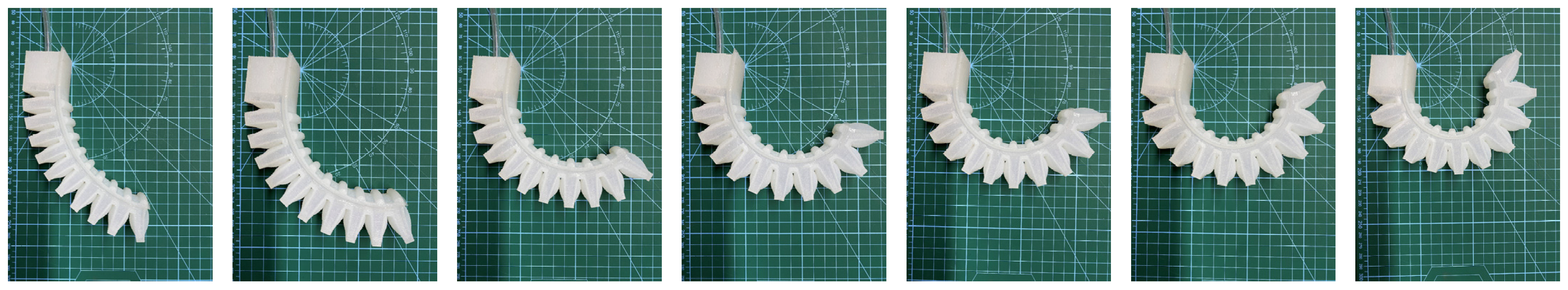
In order to make the soft actuators meet the design requirements, this study focused on manufacturing soft actuators using the casting method. Firstly, we used Solidworks software to design the silicone casting mold of the soft actuator according to the structural design requirements of the above soft actuators, and printed out the silicone mold using 3D printing technology. Then, the two parts of the E620 series silica gel, A and B, were mixed strictly in a ratio of 1:1 and stirred well with a glass rod. Then, the mixed silica gel solution was placed into a sealed container connected to a vacuum pump for defoaming, and when no bubbles overflowed from the surface of the silica gel solution, the defoaming was completed. Then, the completely defoamed silica gel solution was removed and poured into the molds of the soft actuators with a silicone release agent applied to their surfaces. Finally, the silica gel solution was ready to solidify, after 6 h of standing at 25 °C. The process of making a soft actuator brake is shown in Figure 4. The finished experimental products of the zero-degree-angle, five-degree-angle, and hybrid variable-degree-angle soft actuators are shown in Figure 5.
2.4. Experimental Platform
In order to better and more accurately control the pressure load applied to the soft actuators, this study used the IPCU2 drive control unit, which can output a constant gas pressure from −90 kPa to 300 kPa, and at the same time can display the set air pressure value and the air pressure value in the gas chamber of a soft actuator. The experimental platform was built as shown in Figure 6, and mainly consisted of an air compressor, a drive control unit, soft actuators, a stand, and a digital board. The main working principle of the experimental platform, first of all, was that the air compressor would compress the air and transmit the high air pressure to the drive controller. Then, the output air pressure was set by adjusting the knob of the controller, and then the controller would transmit the output-rated air pressure to the soft actuators.
3. Finite Element Simulation Model
3.1. Constitutive Model of Hyperelastic Materials
In order to improve the accuracy of the ABAQUS finite element simulation results, the first mechanical analysis of the silicone material of the soft actuators was conducted. Due to the consideration that the deformation of the soft drive was a medium or large deformation, the Yeoh model was selected.
The Yeoh model, proposed by the American scientist Yeoh, is a typical intrinsic model of hyperelastic materials, suitable for simulating the hyperelastic deformation behavior of large-deformation materials, and its strain energy density function is
where N is the order of the strain energy density function. and are the material parameters. For incompressible materials, J = 1. Then, the Yeoh model can be simplified as:
In order to facilitate the calculation and simulation analysis, the second-order expansion of the Yeoh model is usually used to describe the mechanical properties of the hyperelastic materials, so that N = 2 obtains the second-order expansion of the Yeoh model:
Assume isotropy and incompressibility of a rubber material. The strain energy density function is expressed as:
Further, we find the following:
where, I1, I2, I3 are the deformation tensor invariants. λ1, λ2, λ3 are the main elongation ratios. is the strain in the direction of the main axis.
The stress–strain relationship of a rubber material can be expressed by taking the partial derivative of the strain energy density function, W, with respect to the principal elongation ratio, . This stress–strain form consists of what Piola–Kirchhoff and Cauchy–Green have defined as:
From Equations (4)–(6), the relationship between the main axis force and the main elongation ratio was obtained:
For the case of uniaxial tension, t2 = t3 = 0, . The relationship between the principal stress and principal strain and the strain tensor invariant and principal elongation ratio of a silica gel material can be found as follows:
Combining Equations (3), (5) and (6) gives the relationship between the principal stress and principal elongation ratios for Yeoh’s second-order model as:
Numerical analysis based on Equation (10) and the dataset obtained from the uniaxial stretching experiments was able to obtain the coefficients C10 = 0.11 and C20 = 0.02.
3.2. Parameter Setting of Simulation Model
First of all, we used SolidWorks software for 3D modeling of the designed soft drive, and imported the established model into Abaqus software for finite element simulation. In order to better analyze the bending performance of the soft actuator, this time the model used an isotropic hyperelastic material with a density of 1.05 × 10⁻³ kg/m3, and the strain potential was modeled by a second-order Yeoh model with coefficients C10 = 0.11 and C20 = 0.02. At the same time, the soft actuator invoked a large deformation, large strain, contact, and other nonlinear factors during the motion process. In order to facilitate convergence, this study adopted the creation of a static finite element format to solve the problem and consider geometric nonlinearity. The initial increment of the soft actuator simulation model was adjusted to 0.01, the total duration of the analysis step was 1 s, the simulation time step was set to auto-adjustment, and other parameters were kept at the default settings.
In order to prevent the penetration phenomenon of the two adjacent surfaces during the bending deformation of the soft actuator, we chose the self-contact model to simulate the contact between the two adjacent surfaces, and at the same time, for the sake of the accuracy of the results regarding the contact stress and so on, we chose the surface–surface discretization method. The nature of the contact was “frictionless” for tangential behavior and “hard contact” for normal behavior. The contact setup of the two neighboring faces of the soft actuator is shown in Figure 7a. Assuming that the inner surface of the soft actuator was smooth and frictionless, we selected the inner surface of the soft actuator and created a compression load in the Load Manager, which could be realized by setting different parameter values for different compression loads. For this paper, seven main pressure loading conditions were designed, which are 4 kPa, 6 kPa, 8 kPa, 10 kPa, 12 kPa, 14 kPa, and 16 kPa. The effect of gravity is ignored here. The load setup of the soft actuator is shown in Figure 7b. As shown in Figure 7c, for the setting of the boundary conditions of the soft actuator, the ventilated side of the soft actuator was selected as the fully fixed end; that is, the movement of this end faced along the x-axis, y-axis, and z-axis directions, and the rotation around the x-axis, y-axis, and z-axis directions were restricted. In this study, tetrahedral solid cells were used to mesh the soft actuator. Because the material of the soft actuator described in this paper is silicone material, which belongs to the category of incompressible material or nearly compressed material, the in-hybridization formula was chosen to calculate and analyze the grid cells. The meshing of the soft actuator is shown in Figure 7d.
3.3. Mesh Sensitivity and Quality Analysis
On top of the finite element simulation model described above, a sensitivity analysis was performed on the mesh of the finite element simulation model. The reason for this analysis was to determine the correct size of the current mesh and to ensure good results at the lowest computational cost [35]. The finite element simulation models of the zero-degree-angle soft actuator had mesh sizes of 5 mm, 4 mm, 3 mm, and 2 mm with linear (four-node linear tetrahedral cells) or quadratic formulations (ten-node quadratic tetrahedral cells). At a compressive load of 8 kPa, the bending angles of the soft actuator were calculated as 29.1°, 25.18°, 23.56°, and 14.04° for linear formulas for mesh sizes of 5 mm, 4 mm, 3 mm, and 2 mm, respectively, and 56.02°, 58.8°, 59.26°, and 57.99° for quadratic formulas with the same mesh sizes. The experimental result for the soft actuator is 56 for the same compressive load. It can be concluded that as the mesh size decreases, the bending angles calculated using the linear formulation (four-node linear tetrahedral cells) have a larger difference from the results of the experimental bending angles. On the contrary, the bending angles calculated using the quadratic formula (ten-node quadratic tetrahedral cell) indicate a smaller error with respect to the experimental bending angles, which are all within the error range.
In the above-described mesh sensitivity analysis, the mesh quality information of the finite element simulation model was extracted for different operating conditions. As shown in Table 2, the extracted parameter information includes the number of meshes, the number of nodes, the computation time, and the average absolute error. From Table 2, it can be seen that the number of meshes and the average aspect ratio of the grid cells increased as the mesh size decreased. Meanwhile, the computation time of the finite element simulation model increased with the decrease in the mesh size. By analyzing the mesh sensitivity and mesh quality as described above, it can be seen that the mesh size of the finite element simulation model in this paper is 4 mm and the mesh cell type is a ten-node quadratic tetrahedral cell.
The finite element simulation model developed in this paper was utilized to simulate the soft actuator as it was designed in the literature [36]. Under the same design parameters as in the literature, the displacements in the y-axis direction calculated by the theoretical model in this paper were 4.8 mm, 11.6 mm, 16.7 mm, and 19.1 mm, respectively. The average absolute error between the calculated results of the finite element simulation model in this paper and the results of the reference literature is 0.65. The error range is small, indicating that the finite element model in this paper has a certain degree of reliability.
4. Analysis of Experimental and Finite Element Simulation Results
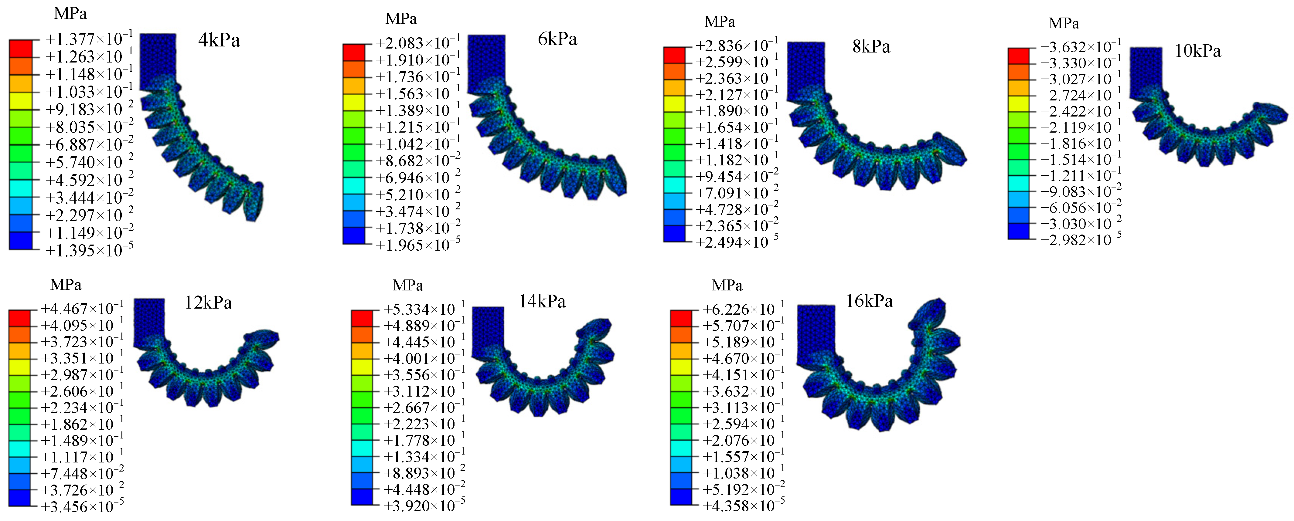
Through the above finite element modeling numerical simulation design and experimental methods, the numerical simulation results of the soft actuators under seven different pressure loads are shown in Appendix A (Figure A1, Figure A2 and Figure A3), and the experimental results are shown in Appendix B (Figure A4, Figure A5 and Figure A6). The experimental and numerical simulations approximated the bending effects of the soft actuators under the same applied compressive loads. Figure 8 shows the comparison between the experimental results and the numerical simulation results of three kinds of soft actuators under different loading pressure strengths. The mean absolute error of the experimental and error results for the zero-degree-angle soft actuator is 0.926, and the root mean square error is 1.132. The mean absolute error of the experimental and error results for the five-degree-angle soft actuator is 1.472, and the root mean square error is 1.513. The mean absolute error of the experimental and error results for the hybrid variable-degree-angle soft actuator is 1.22, and the root mean square error is 1.428. All errors are within acceptable limits, thus verifying the feasibility of the current numerical simulation method. From the simulation results in Figure 8, it can be concluded that the bending angle of the soft actuator changed from 35.35° to 75.18° for the zero-degree angle, from 26.92° to 78.97° for the five-degree-angle, and from 28.06° to 69.59° for the hybrid variable-degree-angle when the pressure load changed from 4 kPa to 16 kPa.
From the bending angle variation of the soft actuators, it can be seen that the five-degree-angle soft actuator has a greater range of angle variation, and that the rate of change of the bending angle is more stable. The bending angle of the soft actuator will reach its limit when the pressure load reaches 14 kPa for the zero-degree-angle soft actuator.
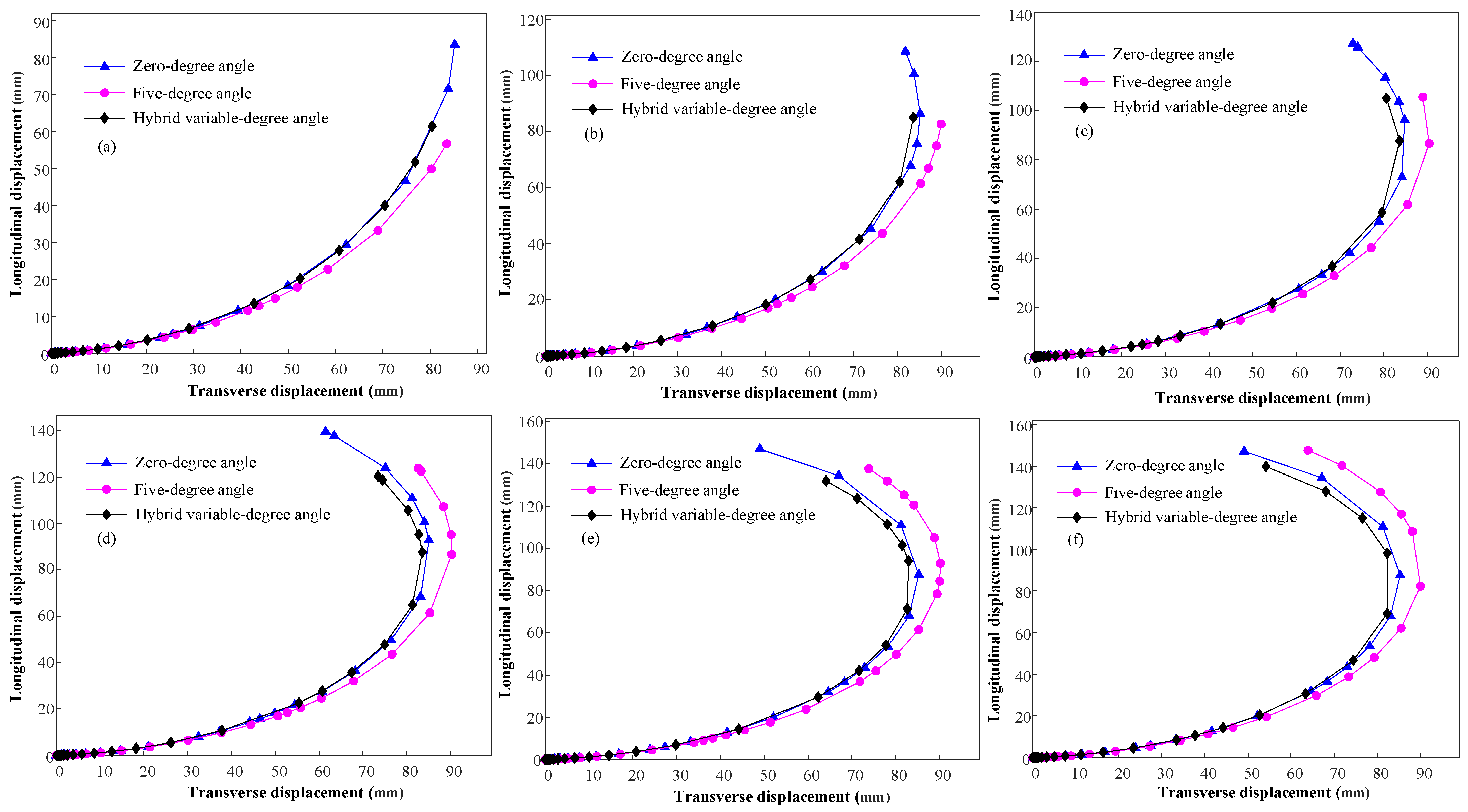
In order to better study the bending performance of soft actuators with different cavity structures, the trends of transverse displacement and longitudinal displacement of different soft actuators were compared and analyzed for this paper.
As shown in Figure 9, the amount of longitudinal displacement variation of the three soft actuators increased with the increasing compressive load, whereas the amount of transverse displacement variation showed a contraction after reaching the maximum value. Since the distance between the two adjacent cavities at the end of the hybrid variable-degree-angle soft actuator was greater than that of the zero-degree-angle soft actuator, the lateral displacement and longitudinal displacement were smaller than that of the zero-degree-angle soft actuator, but the overall trend of the zero-degree-angle and the hybrid variable-degree-angle soft actuators were the same in terms of lateral displacement and longitudinal displacement. The distance between two adjacent cavities of the five-degree-angle soft actuator was greater than that of the zero-degree-angle soft actuator and the hybrid variable-degree-angle soft actuator, so the longitudinal displacement variation of the five-degree-angle soft actuator was less than that of the zero-degree-angle soft actuator and the hybrid variable-degree-angle soft actuator, but the lateral displacement was greater than that of the zero-degree-angle soft actuator and the hybrid variable-degree-angle soft actuator. From the principle of bending angle calculation, it is known that when the longitudinal displacement is deterministic, the larger the transverse displacement, the larger the bending angle of the soft actuator. As for the soft actuators under different pressure loads, at a certain longitudinal displacement, the five-degree-angle soft actuator had a better variation in transverse displacement than the zero-degree-angle and the hybrid variable-degree-angle soft actuators. In other words, the bending performance of the five-degree-angle soft actuator is better than that of the zero-degree-angle and the hybrid variable-degree-angle soft actuators.
5. Conclusions
For this paper, with the purpose of improving the bending performance of the soft actuator, two kinds of soft actuators with different cavity structures were designed and compared with soft actuators with a traditional rectangular structure. The paper analyzed the bending performance of three kinds of soft actuators under different pressure loads and obtained the following conclusions:
- (1)
- Three different soft actuators were fabricated using 3D printing technology and silicone pouring technology, a testing experimental platform of soft actuators was built, and the relationship between the gas pressure and bending angle of the three soft actuators considered in the experiment was investigated. At the same time, ABAQUS software was used to carry out finite element analysis of the soft actuators, and the relationship between the gas pressure and the bending angle of the three kinds of soft actuators under finite element simulation was obtained.
- (2)
- The experimental and simulation results of the three kinds of soft actuators were compared and analyzed, and the mean absolute error between the experimental and simulation results of the zero-degree-angle soft actuator was 0.926, the mean absolute error between the experimental and simulation results of the five-degree-angle soft actuator was 1.472, and the mean absolute error between the experimental and simulation results of the hybrid variable-degree-angle soft actuator was 1.22. The feasibility of the finite element simulation modeling method proposed in this paper was verified through experiments.
- (3)
- The bending performance of three soft actuators with different cavity structures was analyzed, and it was found that the five-degree-angle soft actuator had the largest range of bending angle variation under the same pressure load. Under the same longitudinal displacement, the transverse displacement of the five-degree-angle soft actuator was larger than that of the zero-degree-angle soft actuator and the hybrid variable-degree-angle soft actuator. The bending performance of the soft actuator was significantly improved by changing the cavity tilt angle.
In future research, an effective numerical analysis model can be developed to analyze the five-degree-angle soft actuator bending performance, and the effects of the distance between two adjacent chambers and the chamber thickness on the bending performance of the soft actuator can be investigated.
Author Contributions
Conceptualization, T.F.; data and reference collection, Y.Y.; writing/editing and data and reference collection, T.F. and Y.Y. All authors have read and agreed to the published version of the manuscript.
Funding
The work described in this paper was fully supported by grants from the National Natural Science Foundation of China (Project No. 52205105) and Yunnan Fundamental Research Projects (Project No. 202101AU070160 and 202201AT070145).
Institutional Review Board Statement
Not applicable.
Informed Consent Statement
Not applicable.
Data Availability Statement
This manuscript has associated data in a data repository. All data included in this manuscript are available upon request by contacting the corresponding author.
Conflicts of Interest
The authors declare no conflict of interest.
Appendix A
Figure A1.
Numerical simulation results of the zero-degree-angle soft actuator.
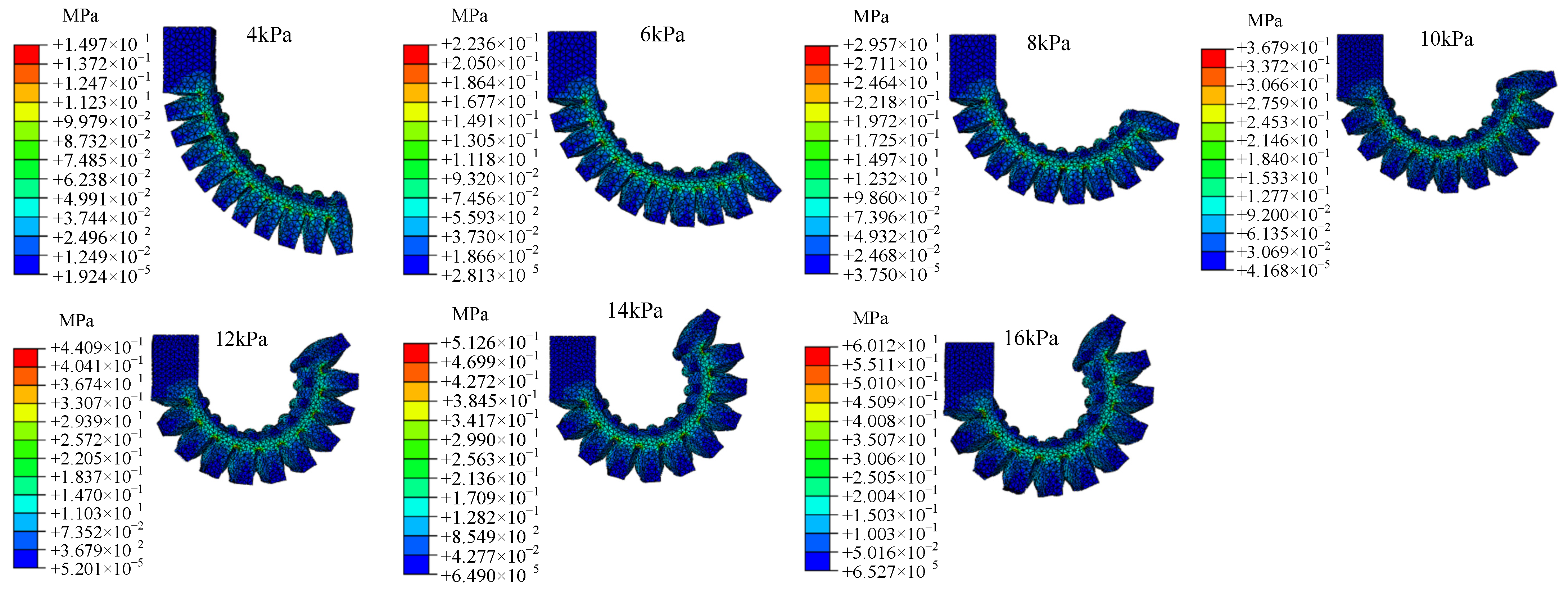
Figure A2.
Numerical simulation results of the five-degree-angle soft actuator.
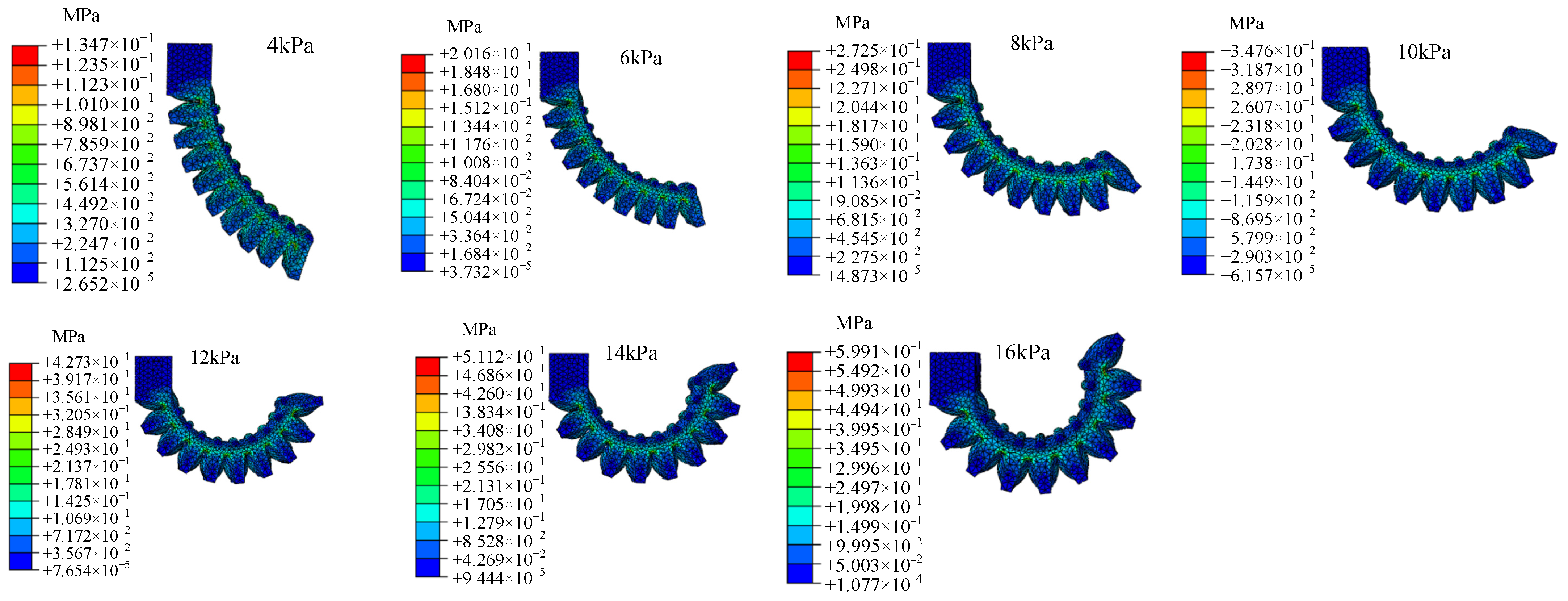
Figure A3.
Numerical simulation results of the hybrid variable-degree-angle soft actuator.
Appendix B
Figure A4.
Experimental results of the zero-degree-angle soft actuator.
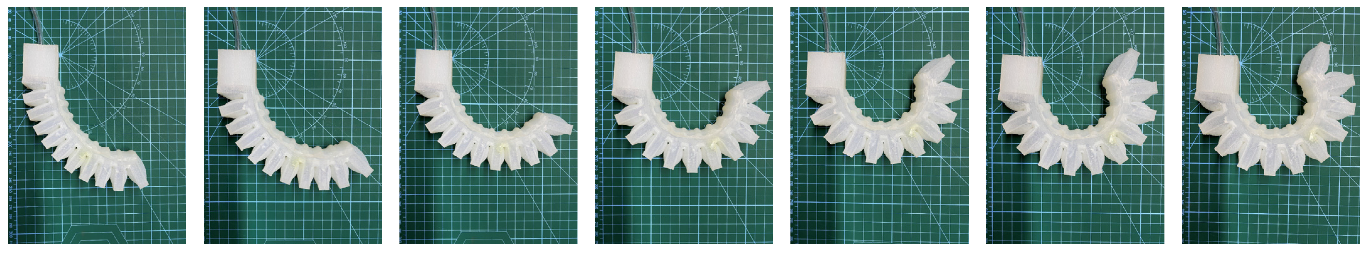
Figure A5.
Experimental results of the five-degree-angle soft actuator.

Figure A6.
Experimental results of the hybrid variable-degree-angle soft actuator.
References
- Shen, H. Meet the soft, cuddly robots of the future. Nature 2016, 530, 24–26. [Google Scholar] [CrossRef] [PubMed] [Green Version]
- Rus, D.; Tolley, M.T. Design, fabrication and control of soft robots. Nature 2015, 521, 467–475. [Google Scholar] [CrossRef] [PubMed] [Green Version]
- Liu, K.; Chen, W.; Yang, W.; Jiao, Z.; Yu, Y. Review of the Research Progress in Soft Robots. Appl. Sci. 2023, 13, 120. [Google Scholar] [CrossRef]
- TolleyMichael, T.; ShepherdRobert, F.; GallowayKevin, C.; WoodRobert, J.; WhitesidesGeorge, M. A resilient, untethered soft robot. Soft Robot. 2014, 1, 213–223. [Google Scholar] [CrossRef] [Green Version]
- Chen, Z.; Liang, X.; Wu, T.; Yin, T.H.; Xiang, Y.H.; Qu, S.X. Pneumatically Actuated Soft Robotic Arm for Adaptable Grasping. Acta Mech. Solida Sin. 2018, 31, 608–622. [Google Scholar] [CrossRef]
- Laschi, C.; Cianchetti, M. Soft robotics: New perspectives for robot bodyware and control. Front. Bioeng. Biotechnol. 2014, 2, 3. [Google Scholar] [CrossRef] [Green Version]
- Whitesides, G.M. Soft Robotics. Angew. Chem.-Int. Ed. 2018, 57, 4258–4273. [Google Scholar] [CrossRef]
- Shintake, J.; Cacucciolo, V.; Floreano, D.; Shea, H. Soft Robotic Grippers. Adv. Mater. 2018, 30, 1707035. [Google Scholar] [CrossRef] [Green Version]
- Wallin, T.J.; Pikul, J.; Shepherd, R.F. 3D printing of soft robotic systems. Nat. Rev. Mater. 2018, 3, 84–100. [Google Scholar] [CrossRef]
- Yap, Y.L.; Sing, S.L.; Yeong, W.Y. A review of 3D printing processes and materials for soft robotics. Rapid Prototyp. J. 2020, 26, 1345–1361. [Google Scholar] [CrossRef]
- Filippova, O.V.; Maksimkin, A.V.; Dayyoub, T.; Larionov, D.I.; Telyshev, D.V. Sustainable Elastomers for Actuators: “Green” Synthetic Approaches and Material Properties. Polymers 2023, 15, 2755. [Google Scholar] [CrossRef] [PubMed]
- Gafford, J.; Ding, Y.; Harris, A.; McKenna, T.; Polygerinos, P.; Holland, D.; Moser, A.; Walsh, C. Shape Deposition Manufacturing of a Soft, Atraumatic, Deployable Surgical Grasper. ASME J. Med. Devices 2014, 8, 030927. [Google Scholar] [CrossRef] [Green Version]
- Zhao, H.C.; O’Brien, K.; Li, S.; Shepherd, R.F. Optoelectronically innervated soft prosthetic hand via stretchable optical waveguides. Sci. Robot. 2016, 1, eaai7529. [Google Scholar] [CrossRef]
- Tawk, C.; Spinks, G.M.; Panhuis, M.I.H.; Alici, G. 3D Printable Linear Soft Vacuum Actuators: Their Modeling, Performance Quantification and Application in Soft Robotic Systems. IEEE/ASME Trans. Mechatron. 2019, 24, 2118–2129. [Google Scholar] [CrossRef]
- Liao, W.; Yang, Z.Q. 3D printing programmable liquid crystal elastomer soft pneumatic actuators. Mater. Horiz. 2022, 10, 576–584. [Google Scholar] [CrossRef]
- Li, T.; Zou, Z.; Mao, G.; Yang, X.; Liang, Y.; Li, C.; Qu, S.; Suo, Z.; Yang, W. Agile and resilient insect-scale robot. Soft Robot. 2019, 6, 133–141. [Google Scholar] [CrossRef]
- Trimmer, B.A.; Lin, H.T. Bone-Free: Soft Mechanics for Adaptive Locomotion. Integr. Comp. Biol. 2014, 54, 1122–1135. [Google Scholar] [CrossRef] [Green Version]
- Jin, H.; Dong, E.; Xu, M.; Liu, C.S.; Alici, G.; Jie, Y. Soft and smart modular structures actuated by shape memory alloy (SMA) wires as tentacles of soft robots. Smart Mater. Struct. 2016, 25, 085026. [Google Scholar] [CrossRef]
- Ranzani, T.; Gerboni, G.; Cianchetti, M.; Menciassi, A. A bioinspired soft manipulator for minimally invasive surgery. Bioinspiration Biomim. 2015, 10, 035008. [Google Scholar] [CrossRef]
- Pi, J.; Liu, J.; Zhou, K.; Qian, M. An Octopus-Inspired Bionic Flexible Gripper for Apple Grasping. Agriculture 2021, 11, 1014. [Google Scholar] [CrossRef]
- Li, J.; Luan, Z.B.; Wang, Y.W.; Huang, M.Z.; Yan, J.; Wang, Y.H. Analysis modeling and experiment of bionic winding soft actuator inspired by plant tendrils. Smart Mater. Struct. 2023, 32, 035023. [Google Scholar] [CrossRef]
- Paek, J.W.; Cho, I.; Kim, J. Microrobotic tentacles with spiral bending capability based on shape-engineered elastomeric microtubes. Sci. Rep. 2015, 5, 10768. [Google Scholar] [CrossRef] [PubMed] [Green Version]
- Wall, V.; Deimel, R.; Brock, O. Selective Stiffening of Soft Actuators Based on Jamming. In Proceedings of the 2015 IEEE International Conference on Robotics and Automation (ICRA), Seattle, WA, USA, 26–30 May 2015; pp. 252–257. [Google Scholar] [CrossRef]
- An, S.Q.; Li, W.H.; Li, J.H.; Zou, H.L.; Deng, Z.C. Tuning Stiffness with Granular Chain Structures for Versatile Soft Robots. Soft Robot. 2023, 10, 493–503. [Google Scholar] [CrossRef]
- Elgeneidy, K.; Neumann, G.; Pearson, S.; Jackson, M.; Lohse, N. Contact Detection and Size Estimation Using a Modular Soft Gripper with Embedded Flex Sensors. In Proceedings of the 2018 IEEE/RSJ International Conference on Intelligent Robots and Systems (IROS), Madrid, Spain, 1–5 October 2018; pp. 498–503. [Google Scholar] [CrossRef] [Green Version]
- Yamaguchi, A.; Takemura, K.; Yokota, S.; Edamura, K. A robot hand using electro-conjugate fluid: Grasping experiment with balloon actuators inducing a palm motion of robot hand. Sens. Actuators A Phys. 2012, 174, 181–188. [Google Scholar] [CrossRef]
- Zhou, J.S.; Chen, S.; Wang, Z. A Soft-Robotic Gripper with Enhanced Object Adaptation and Grasping Reliability. IEEE Robot. Autom. Lett. 2017, 2, 2287–2293. [Google Scholar] [CrossRef]
- Mosadegh, B.; Polygerinos, P.; Keplinger, C.; Wennstedt, S.; Shepherd, R.F.; Gupta, U.; Shim, J.; Bertoldi, K.; Walsh, C.J.; Whitesides, G.M. Pneumatic Networks for Soft Robotics that Actuate Rapidly. Adv. Funct. Mater. 2014, 24, 2163–2170. [Google Scholar] [CrossRef] [Green Version]
- Chen, X.Q.; Zhang, X.; Liu, H.W.; Huang, Y.Y. Design and development of a soft robotic manipulator. Int. J. Mech. Mater. Des. 2020, 16, 309–321. [Google Scholar] [CrossRef]
- Wang, Y.X.; Xu, Q.S. Design and Fabrication of a New Dual-Arm Soft Robotic Manipulator. Actuators 2019, 8, 5. [Google Scholar] [CrossRef] [Green Version]
- Li, X.L.; Zheng, T.J.; Sui, D.B.; Lin, N.G.; Zhang, Q.H.; Zhao, J.; Zhu, Y.H. A 3D printed variable cross-section pneumatic soft manipulator with high-precision positioning capability: Design and control implementation. Sens. Actuators A Phys. 2022, 342, 113644. [Google Scholar] [CrossRef]
- Koivikko, A.; Raei, E.S.; Sariola, V.; Mosallaei, M.; Mantysalo, M. Soft Actuators with Screen-Printed Curvature Sensors; IEEE Sensors: Glasgow, UK, 2017; pp. 1–3. [Google Scholar] [CrossRef]
- Liu, S.F.; Wang, F.J.; Liu, Z.; Zhang, W.; Tian, Y.L.; Zhang, D.W. A Two-Finger Soft-Robotic Gripper with Enveloping and Pinching Grasping Modes. IEEE/ASME Trans. Mechatron. 2021, 26, 146–155. [Google Scholar] [CrossRef]
- Lotfiani, A.; Zhao, H.C.; Shao, Z.F. Torsional Stiffness Improvement of a Soft Pneumatic Finger Using Embedded Skeleton. J. Mech. Robot.-Trans. ASME 2020, 12, 011016. [Google Scholar] [CrossRef]
- Íñiguez-Macedo, S.; Lostado-Lorza, R.; Escribano-García, R.; Martínez-Calvo, M.Á. Finite Element Model Updating Combined with Multi-Response Optimization for Hyper-Elastic Materials Characterization. Materials 2019, 12, 1019. [Google Scholar] [CrossRef] [PubMed] [Green Version]
- Xu, Q.P.; Liu, J.Y. Modeling and Simulation of Pneumatic Soft Actuator with Multiple Chambers. J. Shanghai Jiaotong Univ. 2020, 54, 551–561. Available online: https://xuebao.sjtu.edu.cn/CN/Y2020/V54/I6/551 (accessed on 20 July 2023).
Figure 1.
The cavity deformation principle of a single soft actuator: (a) before deformation; (b) after deformation.
Figure 1.
The cavity deformation principle of a single soft actuator: (a) before deformation; (b) after deformation.

Figure 2.
Structure diagram of soft actuators: (a) the zero-degree-angle soft actuator; (b) the five-degree-angle soft actuator; (c) the hybrid variable-degree-angle soft actuator.
Figure 2.
Structure diagram of soft actuators: (a) the zero-degree-angle soft actuator; (b) the five-degree-angle soft actuator; (c) the hybrid variable-degree-angle soft actuator.
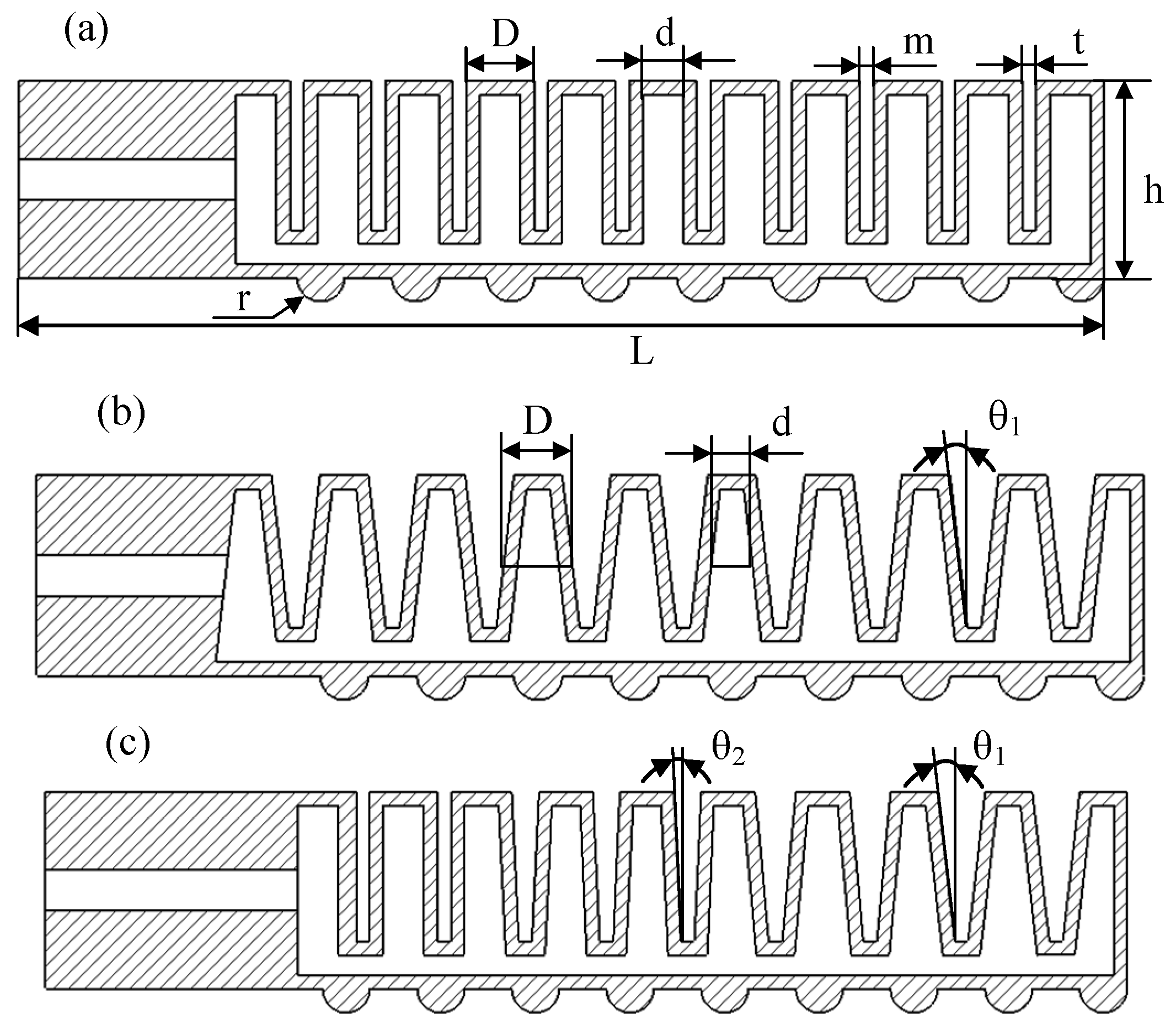
Figure 3.
Bending degree angle calculation model.
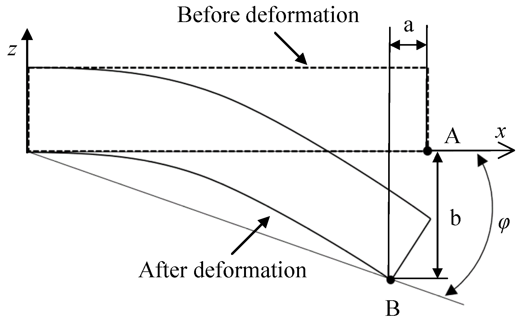
Figure 4.
Soft actuators production process: A and B are E620 series silicone.
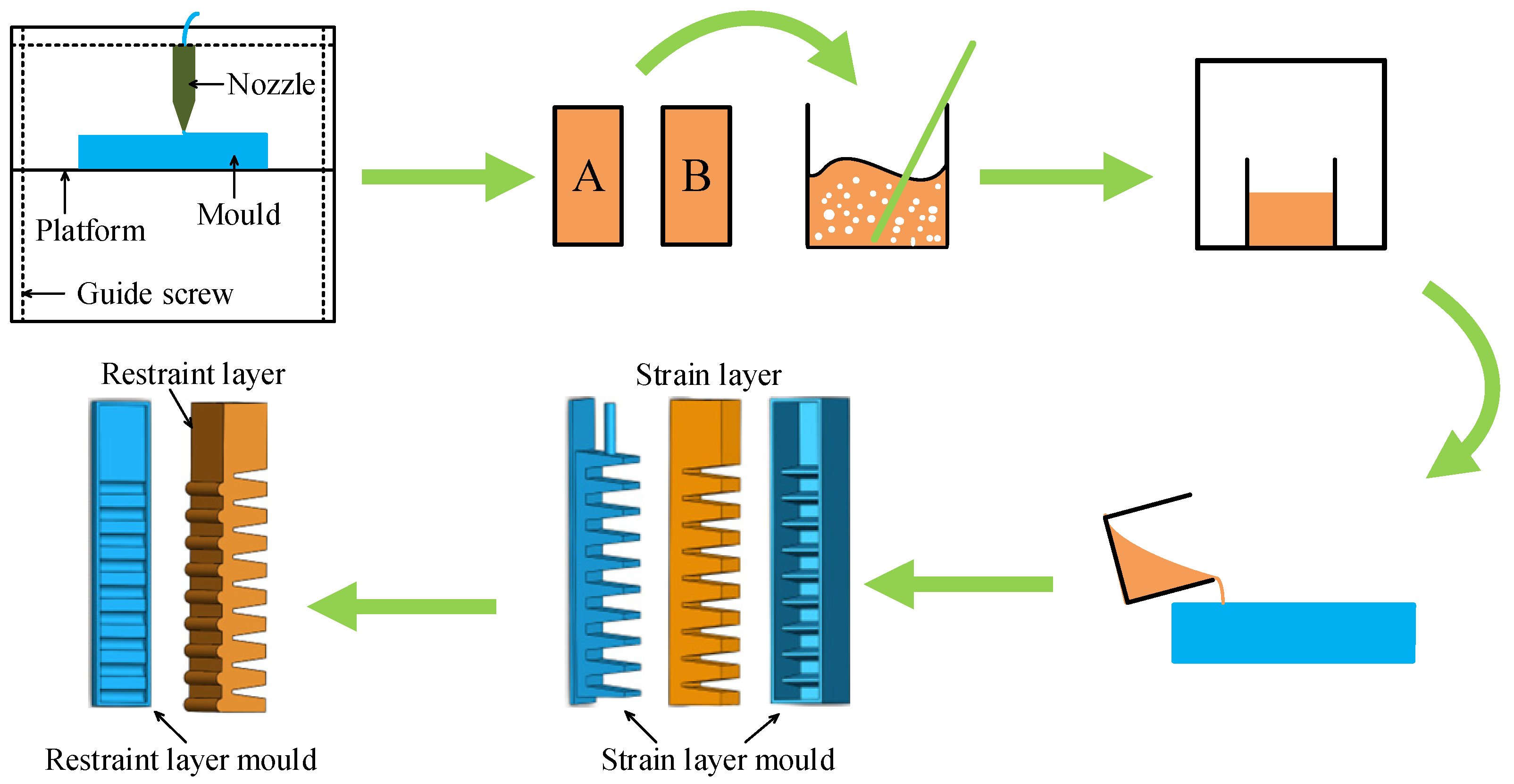
Figure 5.
Three kinds of soft actuators: finished products: (a) the zero-degree-angle soft actuator; (b) the five-degree-angle soft actuator; (c) the hybrid variable-degree-angle soft actuator.
Figure 5.
Three kinds of soft actuators: finished products: (a) the zero-degree-angle soft actuator; (b) the five-degree-angle soft actuator; (c) the hybrid variable-degree-angle soft actuator.
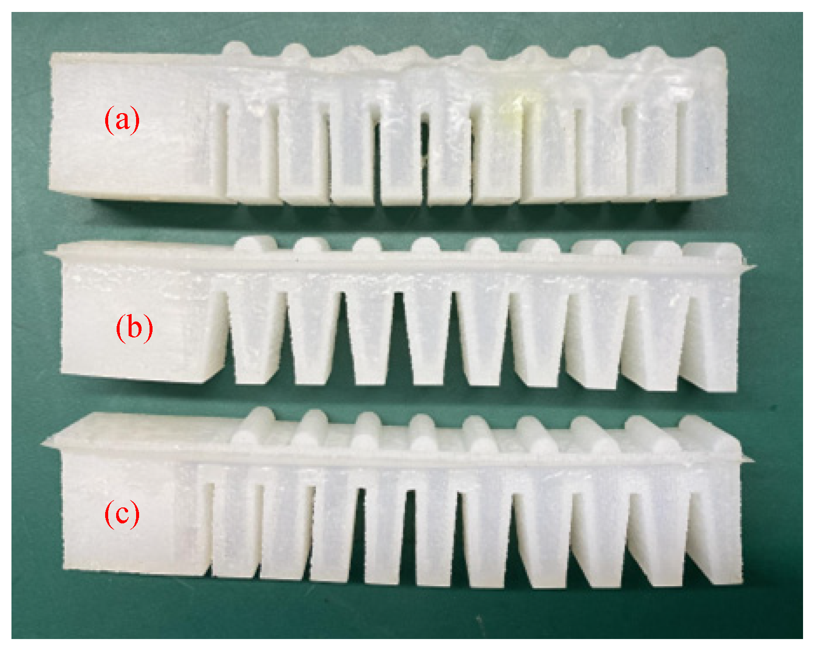
Figure 6.
Soft actuators experimental platform.
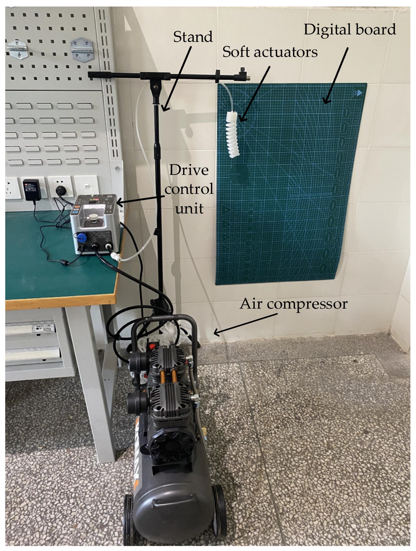
Figure 7.
Numerical simulation design: (a) the interactions; (b) the pressure load; (c) the boundary condition; (d) the mesh.
Figure 7.
Numerical simulation design: (a) the interactions; (b) the pressure load; (c) the boundary condition; (d) the mesh.
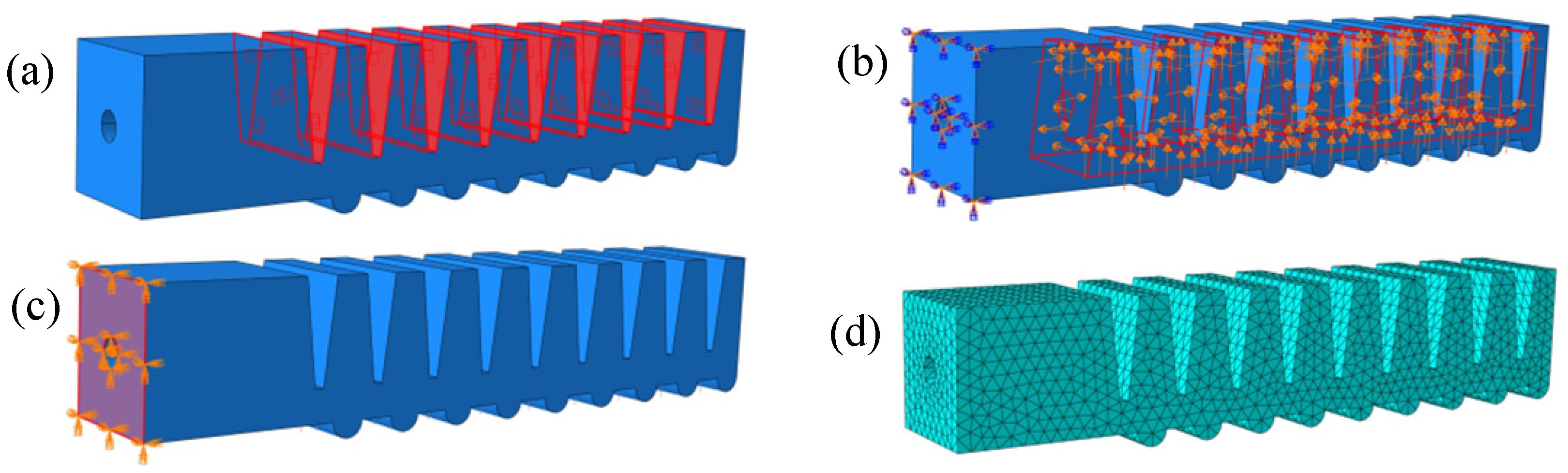
Figure 8.
Comparison of experimental and numerical simulation results of three kinds of soft actuators.
Figure 8.
Comparison of experimental and numerical simulation results of three kinds of soft actuators.
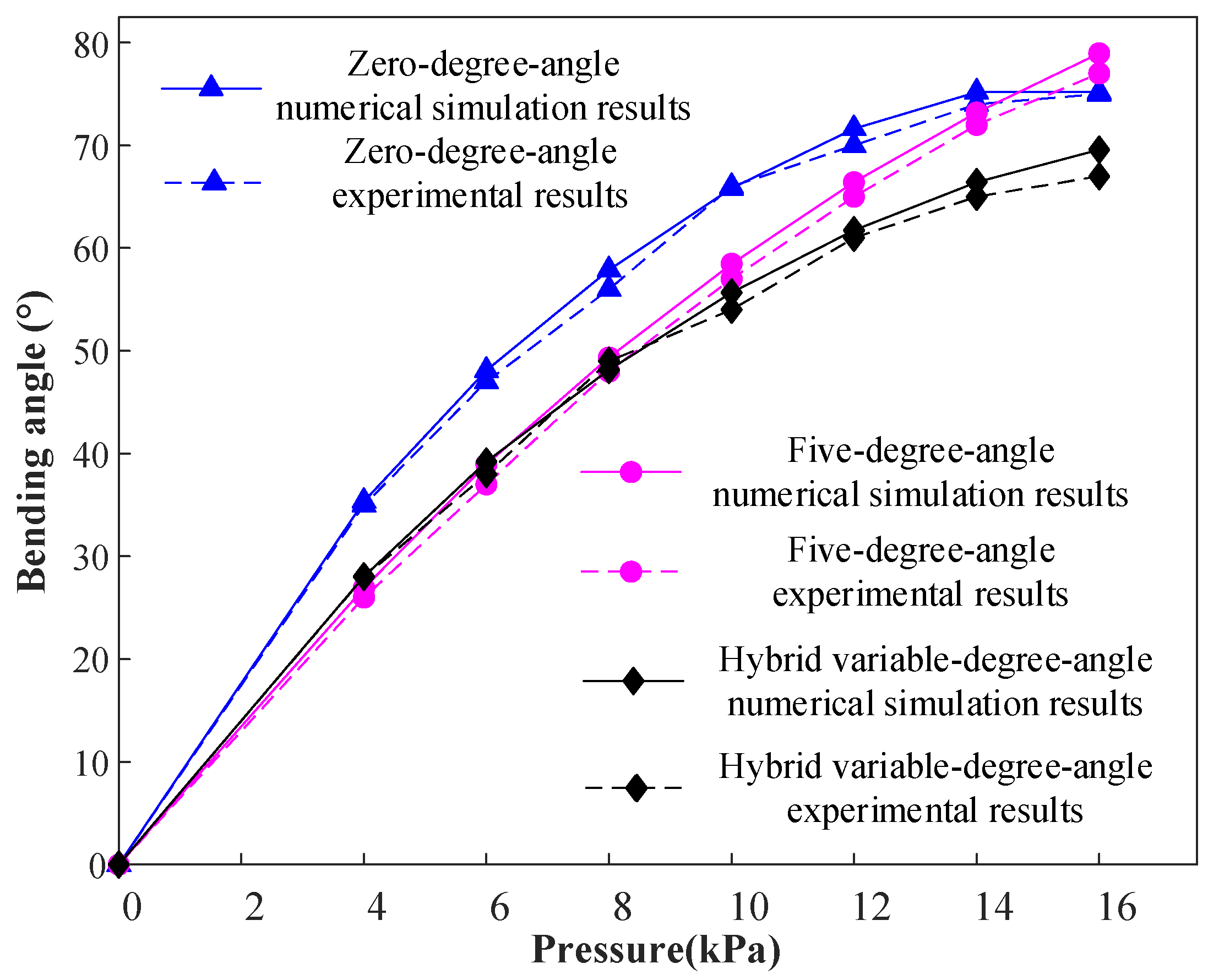
Figure 9.
The variation trends of lateral displacement and longitudinal displacement under different pressure loads: (a) 6 kPa; (b) 8 kPa; (c) 10 kPa; (d) 12 kPa; (e) 14 kPa; (f) 16 kPa.
Figure 9.
The variation trends of lateral displacement and longitudinal displacement under different pressure loads: (a) 6 kPa; (b) 8 kPa; (c) 10 kPa; (d) 12 kPa; (e) 14 kPa; (f) 16 kPa.

Table 1.
Silica gel material parameters.
| Model | Hardness/A | Tensile Strength /MPa | Tear Strength KN/m | Elongation /% | Density Kg/m3 |
|---|---|---|---|---|---|
| E615 | 15 ± 2 | 4.2 | 12 ± 2 | 470 | 1.05 × 10⁻⁹ |
| E620 | 20 ± 2 | 4.7 | 20 ± 2 | 520 | 1.05 × 10⁻⁹ |
| E626 | 25 ± 2 | 5.2 | 20 ± 2 | 470 | 1.07 × 10⁻⁹ |
Table 2.
Silicone material parameters.
| Size [mm] | Elements | Average Aspect Ratio | Nodes | Time [s] | MAE [°] |
|---|---|---|---|---|---|
| (Linear/Quadratic) | (Linear/Quadratic) | (Linear/Quadratic) | |||
| 2 | 88,542 | 1.49 | 88,542/146,475 | 326/2080 | 14.04/2 |
| 3 | 21,488 | 1.58 | 7055/44,348 | 76/540 | 23.56/3.26 |
| 4 | 14,953 | 1.65 | 5430/28,077 | 48/350 | 25.18/2.8 |
| 5 | 8234 | 2.06 | 2150/15,515 | 54/158 | 29.1/0.02 |
Disclaimer/Publisher’s Note: The statements, opinions and data contained in all publications are solely those of the individual author(s) and contributor(s) and not of MDPI and/or the editor(s). MDPI and/or the editor(s) disclaim responsibility for any injury to people or property resulting from any ideas, methods, instructions or products referred to in the content. |
© 2023 by the authors. Licensee MDPI, Basel, Switzerland. This article is an open access article distributed under the terms and conditions of the Creative Commons Attribution (CC BY) license (https://creativecommons.org/licenses/by/4.0/).
Share and Cite
MDPI and ACS Style
Yu, Y.; Fu, T. Design and Experimental Study of Cavity Structure of Pneumatic Soft Actuator. Actuators 2023, 12, 314. https://doi.org/10.3390/act12080314
AMA Style
Yu Y, Fu T. Design and Experimental Study of Cavity Structure of Pneumatic Soft Actuator. Actuators. 2023; 12(8):314. https://doi.org/10.3390/act12080314
Chicago/Turabian StyleYu, Yang, and Tao Fu. 2023. "Design and Experimental Study of Cavity Structure of Pneumatic Soft Actuator" Actuators 12, no. 8: 314. https://doi.org/10.3390/act12080314
Note that from the first issue of 2016, this journal uses article numbers instead of page numbers. See further details here.