Article

Efficient Long-Lasting Energy Generation Using a Linear-to-Rotary Conversion Triboelectric Nanogenerator

1
Department of Mechatronics Engineering, Korea University of Technology & Education, 600, Chungjeol-ro, Byeongcheon-myeon, Dongnam-gu, Cheonan-si 31253, Republic of Korea
2
Advanced Mobility System Group, Korea Institute of Industrial Technology (KITECH), 320 Techno sunhwan-ro, Yuga-eup, Dalseong-gun, Daegu 42994, Republic of Korea
3
Robot Platform Team, Samsung Research Seoul R&D Campus, Umyeon dong 33, Seongchon-gil, Seocho-gu, Seoul 06765, Republic of Korea
*
Authors to whom correspondence should be addressed.
Actuators 2024, 13(10), 396; https://doi.org/10.3390/act13100396
Submission received: 12 August 2024 / Revised: 30 September 2024 / Accepted: 2 October 2024 / Published: 3 October 2024
(This article belongs to the Section Actuator Materials)

Abstract

:
Triboelectric nanogenerators (TENGs) are a viable energy-harvesting technology that can harness kinetic energy from various environmental sources. TENGs primarily utilize linear and rotational motion as their kinetic energy sources. In the contact/separation mode, the primary mode of operation for linear motion, one cycle of AC output is generated with a single push. If the output can be sustained for an extended period from a single push, the potential applications for TENGs would significantly expand. In this study, we propose an innovative Linear-to-Rotary Conversion Triboelectric Nanogenerator (LRC-TENG), which incorporates a gear structure to convert linear motion into rotational motion and employs charge pumping to achieve efficient, prolonged output. The proposed TENG can sustain AC output for 3 s with a single push. This LRC-TENG is particularly well suited for applications such as stairways requiring safety lighting at night. Utilizing the LRC-TENG, when a person steps on a stair, it can illuminate the stairway for 3 s through more than 236 LEDs, ensuring safety during nighttime walking. This solution aids in guaranteeing pedestrian safety at night.

1. Introduction

Energy-harvesting technology is being developed to utilize ambient wasted energy for powering relatively low-power devices effectively [1,2]. Among the many energy-harvesting technologies, the triboelectric nanogenerator (TENG) has achieved remarkable growth since it was first proposed in 2012 [3]. TENG has been developed by many researchers due to its advantages such as high efficiency, simple processes, and eco-friendly materials, and it is now on the verge of commercialization in several fields [4,5,6]. TENG is based on the combined effects of contact electrification and electrostatic induction and can generate electricity from almost any form of mechanical kinetic energy [7,8]. The main mechanical kinetic energy sources utilized in TENGs are linear motion and rotary motion. The primary operating modes of TENGs include the contact/separation mode, sliding mode, single-electrode mode, and free-standing mode [9,10]. Among these, the contact/separation mode and single-electrode mode mainly utilize linear motion, while the sliding mode and free-standing mode primarily utilize rotary motion. Linear motion is highly utilized because it has a simple TENG structure and most mechanical kinetic energy in nature is linear. However, TENGs that directly utilize linear motion can only generate one AC output per contact/separation cycle [11,12]. On the other hand, rotary motion is suitable for generating continuous AC output [13,14,15].
In this study, we propose an innovative Linear-to-Rotary Conversion Triboelectric Nanogenerator (LRC-TENG) that converts linear motion into rotary motion to create continuous AC output, and by charge pumping the triboelectric potential generated in the contact/separation mode TENG through linear motion into a rotary sliding mode TENG, we maximize efficiency and maintain AC output for a long duration. Several proposals have been made to mechanically convert linear motion into rotary motion [16,17,18]. One such structure involves converting the motion of wind or fluid into rotary motion through a fan. Pushing is a frequently occurring form of linear motion, such as when a person or an animal steps on the ground, a car passes over a road, or a person pushes a door. When substantial linear motion is effectively converted into rotary motion through appropriate mechanical elements, it is possible to generate high-utility, long-duration AC power through a rotary sliding TENG mode [19].
The charge-pumping technology in TENGs was introduced by the research team of ZL Wang [20,21,22,23]. This technology utilizes the triboelectric potential from other TENGs to enhance the output of the Main TENG [24,25,26]. Through this charge-pumping technology, greater power can be generated by adding externally introduced potential differences to the self-generated potential differences. We utilize linear motion for two purposes: One is to directly use the linear motion in the contact/separation TENG structure to generate the potential used for charge pumping. The other is to convert the linear motion into rotary motion through mechanical elements and use it as the driving force for a rotary sliding TENG with charge pumping. Through this innovative combined electrical–mechanical structure, we can drive a rotary sliding TENG with an average operating time of 3 s and a rotational speed of 500 rpm from a single push, achieving more than a 30% increase in output compared to when charge pumping is not applied. The proposed LRC-TENG is suitable for applications where long-duration output is advantageous from a single impact pushing. Suggested applications include steps on night walking paths and speed bumps for vehicles.

2. Materials and Methods

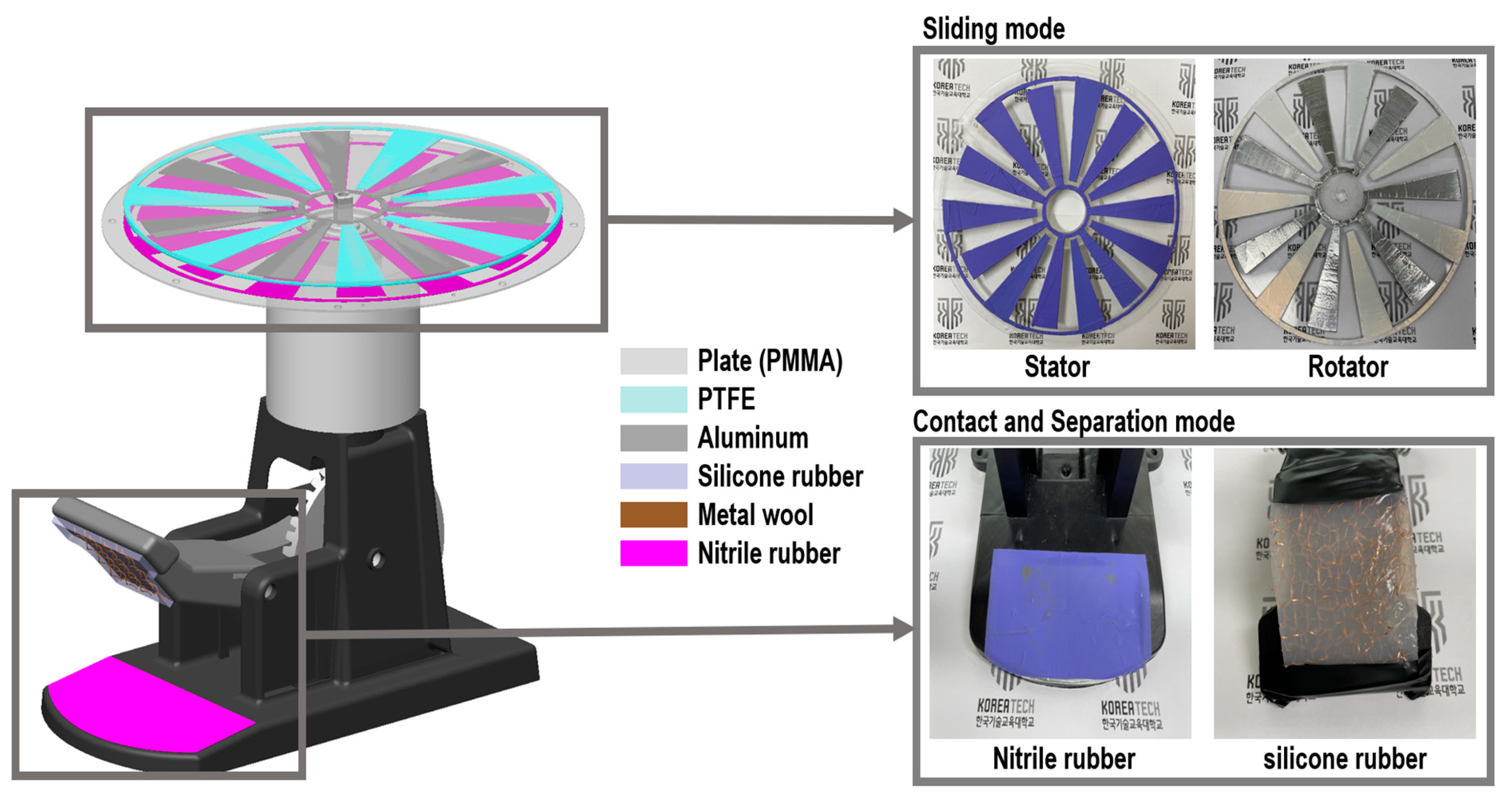
2.1. Fabrication Process of the Triboelectric Nanogenerator (TENG) Device

The TENG in contact and separation mode was fabricated by layering a nitrile film on an aluminum film electrode as the tribo-positive material. The tribo-negative material was fabricated through the following process: first, a magnetic bar was used to stir a 1:1 ratio of part A (D.S. NV10) and part B (curing agent) for 5 min. A 0.9 g copper wool electrode was mixed into the properly stirred silicone rubber; afterward, 17 g of this mixture was poured into a mold and dried for approximately 6 h at room temperature (23 °C). In the overall tribo-negative structure, the silicone rubber acts as the tribo-negative material, while the copper wool serves as the electrode.
The fabrication of the TENG in sliding mode is shown in Figure 1. The stator part involves layering an aluminum electrode pattern on a PMMA disk structure and placing nitrile rubber as the tribo-material on top. The rotator part is completed by layering an aluminum electrode pattern on a PMMA disk structure and placing PTFE as the tribo-material on top.

2.2. Evaluation of LRC-TENG

To measure the electrical output characteristics of the LRC-TENG, a servo motor (custom-made) capable of verifying speeds from 50 to 3000 rpm, an oscilloscope (TBS 2202 B, Tektronix, Beaverton, OR, USA), a current amplifier (DLPCA-200, Femto, Berlin, Germany), a high-voltage probe (P5100A, Tektronix, Beaverton, OR, USA), and a DC motor (K7DS1, GGM, Gyeonggi, Republic of Korea) were used. The servo motor was controlled with an AC signal to adjust the rotational rpm for testing the LRC-TENG at various speeds.

3. Device Design

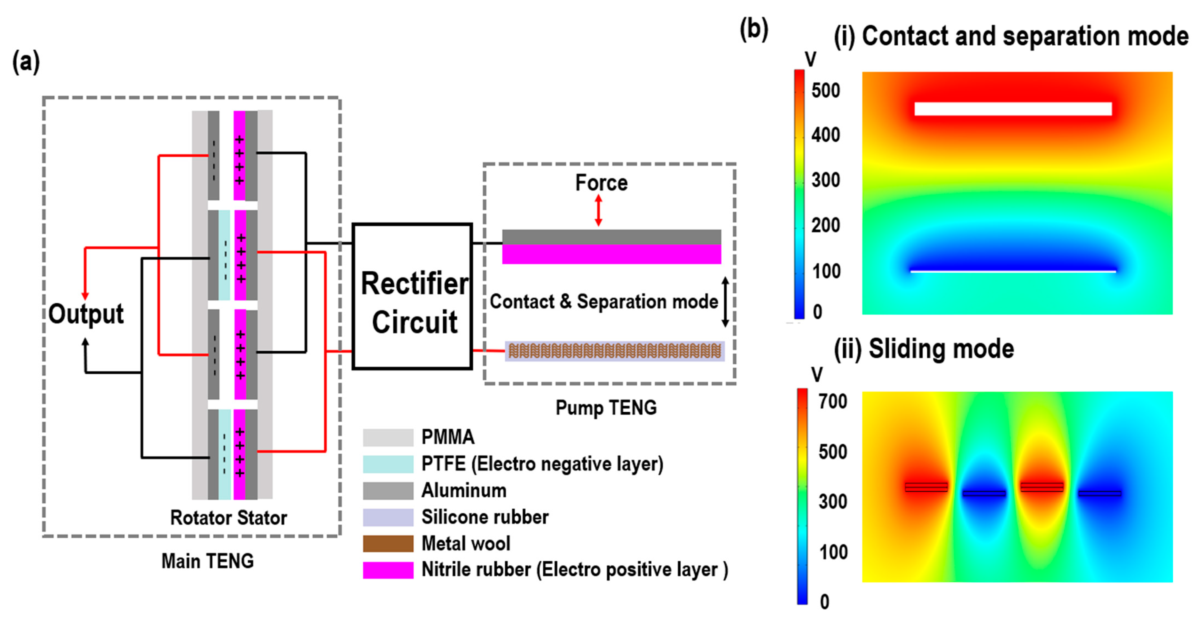
3.1. Parts of the Charge Pumping

The LRC-TENG is composed of two TENGs. As shown in Figure 2a, one is the Pump TENG, which operates through the push force. Its role is to generate a higher potential for the second part, the Main TENG. It operates in contact and separation mode, and the potential generated by triboelectric charging is delivered to the stator of the Main TENG through a rectifier circuit. The Main TENG operates in rotary sliding mode and generates power output. During rotation, the inner surfaces of the stator and rotator with different potentials face each other, as well as the inner surfaces of the stator and rotator with the same potentials. These processes repeat with the rotation angle, and the remaining charges are transferred as output to achieve electrical neutrality between the facing surfaces [27,28]. This output is the final electrical output of the Main TENG.
Figure 2b shows the electric field formed when a potential difference occurs in the Pump TENG and Main TENG. This result is derived from the COMSOL software. In (i), the contact and separation mode shows the potential difference formed by the contact and separation actions and the charge movement caused by the triboelectric effect. In (ii), the sliding mode simulates the periodic change in potential difference by modeling the positional changes in the moving triboelectric layers. Detailed interpretation conditions are shown in Table 1.

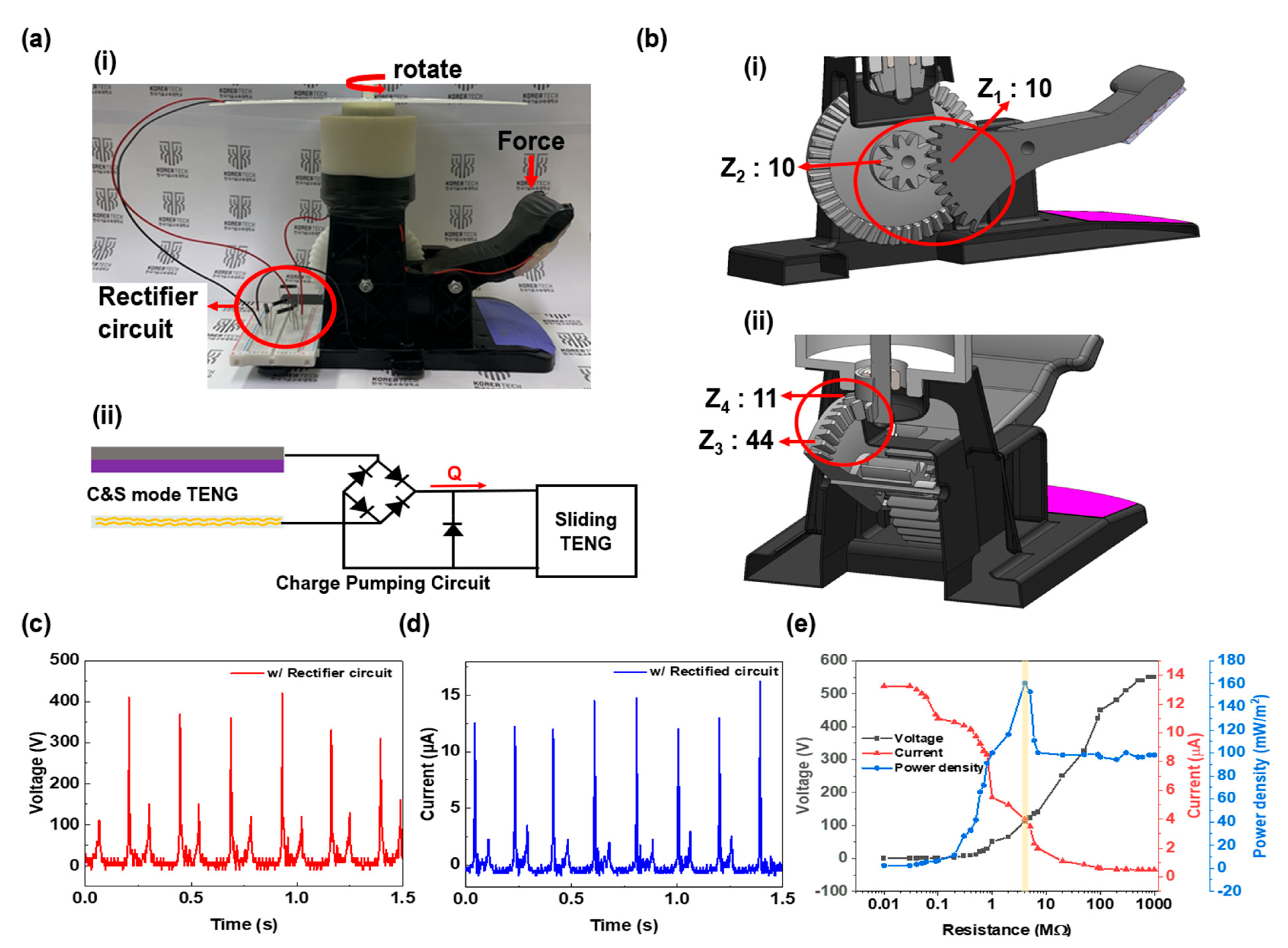
3.2. Mechanical Parts

When examining Figure 3a, it can be seen that the contact and separation mode passes through a rectifier circuit and connects to the sliding mode. Figure 3b shows that a total of four gear parts are used to convert linear motion into rotary motion. The first gear pair converts linear motion into vertical rotary motion. The push force is amplified by N times by the lever and transmitted to gear Z1. In (i), gear Z1 is designed to only transmit force in one direction using a ratchet gear mechanism to prevent reverse rotation. Gears Z1 and Z2 have a gear ratio of 10:10, meaning that Z2 rotates at the same speed as Z1. Gears Z2 and Z3 are mounted on the same circular plate, and this pair of gears converts vertical rotary motion into horizontal rotary motion. Z3 and Z4 have a gear ratio of 44:11, with Z4 rotating four times faster than Z3. In the sliding mode, the rotating electrode plate is arranged horizontally to maintain a uniform gap against gravity, which is advantageous for system stability. By utilizing these four gear parts, a total speed increase of four times can be achieved. Each gear is made of ABS and POM materials and manufactured through CNC machining.
Figure 3a shows the following: (i) The lever structure that transmits the push force has the tribo-negative material part (copper wool + silicone rubber) of the contact and separation TENG mode fixed to it. At the bottom part, where the lever contacts the push force, the tribo-positive material part (nitrile rubber/aluminum film) is set up. (ii) The driving force for the rotary sliding TENG mode is the rotational force transmitted through gear Z4. The triboelectric potential generated by the Pump TENG in the contact and separation mode is delivered to the stator part of the sliding mode Main TENG through a rectifier circuit. This process enhances the charged state of the stator part, positively contributing to the output of the Main TENG. The electrical output of the Pump TENG in the contact and separation mode, after passing through the rectifier circuit, shows a maximum output of 420 V and 15 μA, as shown in Figure 3c,d. Figure 3e demonstrates the change in output with different resistances, showing a maximum output of 180 mW/m2 at 8 MΩ.

4. Linear-to-Rotary Conversion Triboelectric Nanogenerator (LRC-TENG)

4.1. Parameter Design

Figure 4a shows that the final output of the proposed LRC-TENG comes from the Main TENG in sliding mode. Therefore, the final output varies according to the design of the sliding mode TENG. To derive the optimal design, the design parameters were set as the overall diameter D, the gap between the electrodes d, and the number of blades n. The output was measured at different rotational speeds based on the basic design parameters D = 200 mm, d = 15 mm, and n = 7. Figure 4b demonstrates that the rotational speed was controlled through motor control, and the rotational speeds used in the experiment ranged from 50 to 3000 rpm. As the rotational speed increased, the output voltage and current increased proportionally. At the maximum rotational speed of 3000 rpm, the output was 300 V and 2.5 μA. This is the original output of the sliding mode without applying the self-pumping technology.
V = d 0 ω ε 0 ( l x ) Q + σ d 0 x ε 0 ( l x )
In Equation (1), V represents the voltage, and d 0 is a constant related to the thickness of the dielectric. ω   is a constant associated with the contact area between the dielectric and the electrode, and ε 0 is the vacuum permittivity. l denotes the initial distance between the electrode and the dielectric, while x represents the displacement between the electrode and the dielectric that changes over time. Q refers to the amount of charge, and σ represents the triboelectric charge density [29]. Thus, increasing the number of Al blades may increase the contact area, which could have some effect on the output voltage. However, the primary factor for the output increase is the acceleration of charge accumulation due to the increased rotational speed. As the rotational speed increases, the contact cycle between the electrode and dielectric shortens, allowing more charges to accumulate before neutralization occurs. This results in a significant boost in both voltage and current output. We confirmed that the power generation plate with seven blades exhibited the highest output. Based on these results, seven blades were used in the final design. Grooves were machined into the top and bottom of the suspended Al-attached PMMA plate to ensure it remained stationary by aligning it with the PMMA hole of the frame, and the rotating PTFE plate was designed to rotate with the shaft by drilling a shaped hole.
The performance of the LRC-TENG is enhanced by the increased rpm of the PTFE rotating plate. This results in a higher output voltage due to increased charge accumulation and reduced charge decay. As the PTFE rotates, it generates triboelectric charges. However, these charges can diffuse into the atmosphere, come into contact with opposite charges and neutralize, or move through the electrode. By increasing the rpm, the generation cycle time between the Al and PTFE is shortened, which minimizes the decay of the charges and friction before neutralization. Consequently, this leads to greater charge accumulation, thereby boosting both the output voltage and current, as described by the following correlation equation:
I = d q d t = d q d L · v
In this equation, III represents the electric current, L is the horizontal displacement between surfaces, q denotes the triboelectric charges, t is the time required for charge transfer, and v is the rotational velocity. According to Equation (2), as v increases, the contact time between PTFE and Al decreases, which consequently leads to an increase in current.
The output of the Main TENG was efficiently designed through parameter design. The overall diameter D , the thickness of the blades t , and the number of blades n were set differently to measure the output voltage and current at various rotational speeds. These results were obtained without applying charge-pumping technology. The electrodes of the stator and rotator have the same design. The rotator has a rotating plate structure, and a slip ring was installed on the rotation axis to transfer the fixed power from the rotating device, allowing the output to be extracted from the fixed structure. The design with the maximum output, as shown in Figure 5, includes (a) and (b) an outer diameter D = 200   m m (c) and (d) an electrode gap t = 2   m m , and (e) and (f) blade number n = 7 . The LRC-TENG was finalized based on the Main TENG design, and its applicability was evaluated.

4.2. Output Performance and Applications

The final electrical output was measured under the operation induced by an external push force. The push force causes the Pump TENG to generate rotational motion in the Main TENG through the charge-pumping function and a 4-fold gear train. The Main TENG operates in sliding TENG mode with charge pumping from the Pump TENG. The charge pumping delivered to the Main TENG is transmitted through the rectifier circuit connection. We investigated the output performance of the triboelectric nanogenerator (TENG) under two different humidity conditions: 40% and 57%, as well as the effect of charge pumping. Figure 6a,b show the voltage and current outputs at 40% humidity, while Figure 6c,d present the results at 57% humidity. At 40% humidity, the TENG with charge pumping reached a peak voltage of 220 V and a current of 4.8 µA, significantly outperforming the setup without charge pumping, where the maximum values were lower. Charge pumping was performed at 57% humidity, and stable output was shown in Figure 6c,d even when the pedal was moved 20 times. While the output voltage and current were slightly reduced due to increased moisture, the system with charge pumping still maintained a strong and stable performance compared to the system without charge pumping. Moreover, the proposed TENG exhibited continuous alternating current (AC) output for about 3 s from a single push, a result that contrasts with the traditional contact/separation mode that provides one AC output per push cycle. The sustained output is achieved through the rotational force transmitted via the gear train, enabling the TENG to operate at an average speed of 500 rpm from a single push. The long-term stability and performance of the TENG under high humidity conditions (57%) are illustrated in Figure 6c,d, indicating the robustness of the device even after multiple cycles.
By utilizing the continuous and high output of the LRC-TENG for more than 3 s, it can be applied to many fields. The efficient and long-lasting power can be used for sensors that detect shock and pressure, IoT sensors with communication functions, and lights for nighttime safety [30,31,32]. Organic EL lights, though not extremely bright, have excellent light directionality, making them highly visible at night and easy to read text [33,34]. Additionally, their thin film form makes them ideal for nighttime work clothing or sports gear. However, they require a high driving voltage of over 100 V, making stable operation difficult with conventional energy-harvesting technologies. The proposed LRC-TENG provides sufficient driving voltage and duration needed for visibility, making it suitable for organic EL lights. Figure 6e shows the organic EL light illuminated by the power generated from a single push applied to the LRC-TENG. Figure 6f shows the charging graphs of capacitors using the LRC-TENG. Due to efficient output, the capacitors charge in a relatively short time.
Based on these results, the device’s charging capacity was evaluated using the circuit shown in Figure 6f. A full-wave rectifier circuit was constructed with four diodes to charge the capacitor. Figure 6f shows the results obtained at a rotational speed of 600 rpm, demonstrating that it takes 50 s to charge a 2.2 μF capacitor using the fabricated device configuration. Figure 6g demonstrates the use of the charged capacitance to power 236 LEDs. Video S1 shows the 236 LEDs used to demonstrate the output performance of the LRC-TENG. It was confirmed that the device operated very reliably, indicating that the proposed LRC-TENG is suitable for driving low-power devices such as IoT sensors and holds great potential for application in numerous self-powered device fields.

5. Conclusions

In this paper, we proposed an LRC-TENG and experimentally validated its performance. The LRC-TENG converts linear motion into rotary motion to generate continuous AC output and features an innovative function that maintains AC output for an extended period by applying charge-pumping technology. The experimental results showed that a single push could maintain AC output for approximately 3 s, and various outputs could be achieved depending on the rotational speed. This LRC-TENG is suitable for environments such as stairs on nighttime walking paths or speed bumps for cars. Specifically, when applied to stairs, a single step can illuminate the stairway with over 236 LEDs, significantly enhancing nighttime walking safety. Moreover, the output of the LRC-TENG can be utilized to drive safety guide devices such as organic EL lights. Stable operation was confirmed through experiments on capacitance charging and low-power device operation. Based on this performance and potential applications, the LRC-TENG holds great promise for self-powered device fields, including IoT sensors. This study enhances the feasibility of energy-harvesting technology and is expected to promote innovative applications in the field of low-power devices.

Supplementary Materials

The following supporting information can be downloaded at https://www.mdpi.com/article/10.3390/act13100396/s1, Video S1: We turned on 236 LEDs to check the output performance of the LRC-TENG.

Author Contributions

All the authors contributed to the study. Conceptualization, methodology, writing—original draft, writing—review, and editing were performed by J.S. and S.J. Methodology, writing—review, and editing were carried out by S.J. and D.H.K. Experiment, writing—review, and editing were carried out by S.J., J.S. and J.P. The simulation, writing—review, and editing were performed by S.J. and J.Y. The validation, resources, writing—review, and editing were carried out by J.P. All authors have read and agreed to the published version of the manuscript.

Funding

This research was supported by the Education and Research Promotion program of KOREATECH in 2023 and by “Regional Innovation Strategy (RIS)” through the National Research Foundation of Korea (NRF) funded by the Ministry of Education (MOE) (2021RIS-004).

Data Availability Statement

The data are available upon reasonable request from the corresponding author.

Conflicts of Interest

The authors declare no conflicts of interest.

References

  1. Wang, J.; Zi, Y.; Li, S.; Chen, X. High-voltage applications of the triboelectric nanogenerator—Opportunities brought by the unique energy technology. MRS Energy Sustain. 2020, 6, E17. [Google Scholar] [CrossRef]
  2. Wang, A.C.; Wu, C.; Pisignano, D.; Wang, Z.L.; Persano, L. Polymer nanogenerators: Opportunities and challenges for large-scale applications. J. Appl. Polym. Sci. 2018, 135, 45674. [Google Scholar] [CrossRef]
  3. Fan, F.R.; Tian, Z.Q.; Wang, Z.L. Flexible triboelectric generator. Nano Energy 2012, 1, 1328–1334. [Google Scholar] [CrossRef]
  4. Wu, C.; Wang, A.C.; Ding, W.; Guo, H.; Wang, Z.L. Triboelectric nanogenerator: A foundation of the energy for the new era. Adv. Energy Mater. 2019, 9, 1802906. [Google Scholar] [CrossRef]
  5. Furfari, F.A. A history of the Van de Graaff generator. IEEE Ind. Appl. Mag. 2005, 11, 10–14. [Google Scholar] [CrossRef]
  6. Wang, Z.L.; Chen, J.; Lin, L. Progress in triboelectric nanogenerators as a new energy technology and self-powered sensors. Energy Environ. Sci. 2015, 8, 2250–2282. [Google Scholar] [CrossRef]
  7. Niu, S.; Wang, S.; Lin, L.; Liu, Y.; Zhou, Y.S.; Hu, Y.; Wang, Z.L. Theoretical study of contact-mode triboelectric nanogenerators as an effective power source. Energy Environ. Sci. 2013, 6, 3576. [Google Scholar] [CrossRef]
  8. Wang, Z.L.; Wang, A.C. On the origin of contact-electrification. Mater. Today 2019, 30, 34–51. [Google Scholar] [CrossRef]
  9. Choi, Y.S.; Kim, S.W.; Kar-Narayan, S. Materials-related strategies for highly efficient triboelectric energy generators. Adv. Energy Mater. 2021, 11, 2003802. [Google Scholar] [CrossRef]
  10. Lin, L.; Xie, Y.; Niu, S.; Wang, S.; Yang, P.K.; Wang, Z.L. Robust triboelectric nanogenerator based on rolling electrification and electrostatic induction at an instantaneous energy conversion efficiency of ~55%. ACS Nano 2015, 9, 922–930. [Google Scholar] [CrossRef]
  11. Bhatia, D.; Hwang, H.J.; Huynh, N.D.; Lee, S.; Lee, C.; Nam, Y.; Kim, J.G.; Choi, D. Continuous scavenging of broadband vibrations via omnipotent tandem triboelectric nanogenerators with cascade impact structure. Sci. Rep. 2019, 9, 8223. [Google Scholar] [CrossRef] [PubMed]
  12. Hwang, H.J.; Jung, Y.; Choi, K.; Kim, D.; Park, J.; Choi, D. Comb-structured triboelectric nanogenerators for multi-directional energy scavenging from human movements. Sci. Technol. Adv. Mater. 2019, 20, 725–732. [Google Scholar] [CrossRef] [PubMed]
  13. Yong, H.; Chung, J.; Choi, D.; Jung, D.; Cho, M.; Lee, S. Highly reliable wind-rolling triboelectric nanogenerator operating in a wide wind speed range. Sci. Rep. 2016, 6, 33977. [Google Scholar] [CrossRef] [PubMed]
  14. Ren, Z.; Wang, Z.; Liu, Z.; Wang, L.; Guo, H.; Li, L.; Li, S.; Chen, X.; Tang, W.; Wang, Z.L. Energy harvesting from breeze wind (0.7–6 m/s) using ultra-stretchable triboelectric nanogenerator. Adv. Energy Mater. 2020, 10, 2001770. [Google Scholar] [CrossRef]
  15. Zhang, X.; Hu, J.; Yang, Q.; Yang, H.; Yang, H.; Li, Q.; Li, X.; Hu, C.; Xi, Y.; Wang, Z.L. Harvesting multidirectional breeze energy and self-powered intelligent fire detection systems based on triboelectric nanogenerator and fluid-dynamic modeling. Adv. Funct. Mater. 2021, 31, 2106527. [Google Scholar] [CrossRef]
  16. Long, L.; Liu, W.; Wang, Z.; He, W.; Li, G.; Tang, Q.; Guo, H.; Pu, X.; Liu, Y.; Hu, C. High performance floating self-excited sliding triboelectric nanogenerator for micro mechanical energy harvesting. Nat. Commun. 2021, 12, 4689. [Google Scholar] [CrossRef]
  17. Chen, J.; Guo, H.; Hu, C.; Wang, Z.L. Robust triboelectric nanogenerator achieved by centrifugal force induced automatic working mode transition. Adv. Energy Mater. 2020, 10, 2000886. [Google Scholar] [CrossRef]
  18. Li, Q.; Liu, W.; Yang, H.; He, W.; Long, L.; Wu, M.; Zhang, X.; Xi, Y.; Hu, C.; Wang, Z.L. Ultra-stability high-voltage triboelectric nanogenerator designed by ternary dielectric triboelectrification with partial soft-contact and non-contact mode. Nano Energy 2021, 90, 106585. [Google Scholar] [CrossRef]
  19. Wang, J.; Ding, W.; Pan, L.; Wu, C.; Yu, H.; Yang, L.; Liao, R.; Wang, Z.L. Self-powered wind sensor system for detecting wind speed and direction based on a triboelectric nanogenerator. ACS Nano 2018, 12, 3954–3963. [Google Scholar] [CrossRef]
  20. Xu, L.; Bu, T.Z.; Yang, X.D.; Zhang, C.; Wang, Z.L. Ultrahigh charge density realized by charge pumping at ambient conditions for triboelectric nanogenerators. Nano Energy 2018, 49, 625–633. [Google Scholar] [CrossRef]
  21. Cheng, L.; Xu, Q.; Zheng, Y.; Jia, X.; Qin, Y. A self-improving triboelectric nanogenerator with improved charge density and increased charge accumulation speed. Nat. Commun. 2018, 9, 3773. [Google Scholar] [CrossRef] [PubMed]
  22. Liu, W.; Wang, Z.; Wang, G.; Liu, G.; Chen, J.; Pu, X.; Xi, Y.; Wang, X.; Guo, H.; Hu, C. Integrated charge excitation triboelectric nanogenerator. Nat. Commun. 2019, 10, 1426. [Google Scholar] [CrossRef] [PubMed]
  23. Ma, J.; Youn, J.H.; Cho, H.; Park, J.; Kyung, K.U. Highly efficient long-lasting triboelectric nanogenerator upon impact and its application to daily-life self-cleaning solar panel. Nano Energy 2022, 103, 107836. [Google Scholar] [CrossRef]
  24. Wu, J.; Teng, X.; Liu, L.; Cui, H.; Li, X. Eutectogel-based self-powered wearable sensor for health monitoring in harsh environments. Nano Res. 2024, 17, 5559–5568. [Google Scholar] [CrossRef]
  25. He, J.; Guo, X.; Pan, C.; Cheng, G.; Zheng, M.; Zi, Y.; Li, X. High-output soft-contact fiber-structure triboelectric nanogenerator and its sterilization application. Nanotechnology 2023, 34, 385403. [Google Scholar] [CrossRef]
  26. Guo, X.; He, J.; Zheng, Y.; Wu, J.; Pan, C.; Zi, Y.; Li, X. High-performance triboelectric nanogenerator based on theoretical analysis and ferroelectric nanocomposites and its high-voltage applications. Nano Res. Energy 2023, 2, 3. [Google Scholar] [CrossRef]
  27. Niu, S.; Liu, Y.; Chen, X.; Wang, S.; Zhou, Y.S.; Lin, L.; Xie, Y.; Wang, Z.L. Theory of freestanding triboelectric-layer-based nanogenerators. Nano Energy 2015, 12, 760–774. [Google Scholar] [CrossRef]
  28. Bai, P.; Zhu, G.; Liu, Y.; Chen, J.; Jing, Q.; Yang, W.; Wang, Z.L. Cylindrical rotating triboelectric nanogenerator. ACS Nano 2013, 7, 6361–6366. [Google Scholar] [CrossRef]
  29. Niu, S.; Liu, Y.; Wang, S.; Lin, L.; Zhou, Y.S.; Hu, Y.; Wang, Z.L. Theory of Sliding-Mode Triboelectric Nanogenerators. Adv. Mater. 2013, 25, 6184–6193. [Google Scholar] [CrossRef]
  30. Shin, J.; Ji, S.; Cho, H.; Park, J. Highly flexible triboelectric nanogenerator using porous carbon nanotube composites. Polymers 2023, 15, 1135. [Google Scholar] [CrossRef]
  31. Shin, J.; Ji, S.; Yoon, J.; Park, J. Module-type triboelectric nanogenerators capable of harvesting power from a variety of mechanical energy sources. Micromachines 2021, 12, 1043. [Google Scholar] [CrossRef] [PubMed]
  32. Kamilya, T.; Han, D.; Shin, J.; Kwon, S.; Park, J. An Ultrasensitive Laser-Induced Graphene Electrode-Based Triboelectric Sensor Utilizing Trapped Air as Effective Dielectric Layer. Polymers 2024, 16, 26. [Google Scholar] [CrossRef] [PubMed]
  33. Kalinowski, J. Electroluminescence in organics. J. Phys. D Appl. Phys. 1999, 32, R179. [Google Scholar] [CrossRef]
  34. Mitschke, U.; Bäuerle, P. The electroluminescence of organic materials. J. Mater. Chem. 2000, 10, 1471–1507. [Google Scholar] [CrossRef]
Figure 1. Overview of Device Design and Testing Modes: Sliding and Contact/Separation.
Actuators 13 00396 g001
Figure 2. Working Mechanism and Electrostatic Analysis. (a) Structure of Main TENG and Pump TENG. (b) Electrostatic Analysis of (i) Contact and Separation Mode and (ii) Sliding Mode.
Actuators 13 00396 g002
Figure 3. Schematics of Gear Train and Output Performance. (a) (i) Device and (ii) Circuit Diagram of Gear Train. (b) Detailed structure of the gear train. (i) Gear ratio 10:10 (ii) Gear ratio 44:11. (c) Voltage Output of the System with Rectifier Circuit. (d) Current Output of the System with Rectifier Circuit. (e) Output Performance According to Resistance.
Actuators 13 00396 g003
Figure 4. Sliding mode parameter study and output performance test of rotation speed. (a) The parameters of the sliding mode. (b) The output performance test according to rotation speed.
Actuators 13 00396 g004
Figure 5. Sliding mode parameter study and output performance test of various parameters. (a) Voltage output according to disk diameter, D . (b) Current output according to disk diameter, D . (c) Voltage output according to disk thickness, t . (d) Current output according to disk thickness, t . (e) Voltage output according to number of blades, n . (f) Current output according to number of blades, n .
Actuators 13 00396 g005
Figure 6. Evaluation of output performance of charge-pumping mechanism using power supply. (a) Output performance with charge pumping. (b) Output performance without charge pumping. (c) Comparison of charge pumping output performance at 57% humidity. (d) Long-term stability test of LRC−TENG over multiple cycles of operation. (e) Device images before and after EL operation. (f) Voltage charging curves for different capacitance values. (g) LED illumination through LRC −TENG.
Actuators 13 00396 g006
Table 1. Simulation condition.
SymbolNameQuantityUnit
ε r 1 PTFE
Relative permittivity
2.0
Ground0
(Al)
VTerminal voltage500, 700 V
Disclaimer/Publisher’s Note: The statements, opinions and data contained in all publications are solely those of the individual author(s) and contributor(s) and not of MDPI and/or the editor(s). MDPI and/or the editor(s) disclaim responsibility for any injury to people or property resulting from any ideas, methods, instructions or products referred to in the content.

