Article

Novel Extension Control Instrument for Power Wheelchair Based on Kalman Filter Head Motion Detection

1
School of Automation Science and Electrical Engineering, Beihang University, Beijing 100191, China
2
Tianmushan Laboratory, Hangzhou 310023, China
3
School of Mechanical Engineering, Tsinghua University, Beijing 100084, China
*
Author to whom correspondence should be addressed.
Actuators 2024, 13(4), 141; https://doi.org/10.3390/act13040141
Submission received: 22 February 2024 / Revised: 29 March 2024 / Accepted: 3 April 2024 / Published: 11 April 2024

Abstract

:
People with upper limb disabilities or high quadriplegia have extremely high requirements for the maneuverability and functionality of power wheelchairs. Normal wheelchairs cannot meet travel tasks, while smart customized wheelchairs are expensive and cannot be popularized. Therefore, a novel extension control instrument for power wheelchairs with low cost, strong scalability, and convenient usage is proposed, which can realize the control of the wheelchair by sensing a change of head posture. The device is divided into a head motion sensing unit (HMSU) and a wheelchair assistance control unit (WACU). The mapping relationship between the head attitude and the subject’s motion intention is established. The inertial measurement module in the HMSU collects the head attitude data and uses the Kalman filtering method to obtain the accurate Euler angle. The WACU is fixed on the original controller of the wheelchair. The joystick is inserted into the extended control mechanism and controlled, instead of the hand, through a 2-degree-of-freedom servo system combined with the pinion and rack push rod structure, thus controlling the movement of the wheelchair. In proceeding, the system can also detect the distance of objects in the environment in real time through the three-direction (front, left, right) ultrasonic ranging sensors installed on the WACU, with a certain obstacle avoidance function. The prototype experiments prove that the extension control instrument developed in this paper based on the Kalman filter can quickly and accurately identify head motion and accurately control the movement of the wheelchair. It is easy to operate and has strong universality, which presents a new low-cost solution for the travel of patients with disabilities.

1. Introduction

On 16 May 2022, the World Health Organization and UNICEF released a new report showing that one in three, or more than 2.5 billion, people worldwide require at least one assistive device. As the global population ages and the prevalence of noncommunicable diseases increases, this figure will rise to 3.5 billion in 2050 [1]. Power wheelchairs are essential aids to daily life for people with lower limb disabilities or mobility impairment. People who have lost only partial or complete walking function of the lower limb can still obtain limited mobility by using their upper limbs to control a power wheelchair. However, for people with upper limb disabilities, upper limb neurological disorders, quadriplegia, and other more serious physical disabilities, autonomous mobility has always been an inconvenient problem in their lives. They urgently need a power wheelchair control system without hand control to meet their independent travel demand.
To better satisfy the needs of independent travel of people with disabilities, researchers have designed and developed a large number of power wheelchairs with different structures and functions in the past decades. For example, Karman is an online manufacturing and medical supply store that manufactures more than 100 different models of wheelchairs, ranging from vehicles to light wheelchairs to ultralight wheelchairs. Additionally, EZLite creates foldable chairs that turn into a compact shape that is easy for transportation. In China, electric wheelchair products from Yuwell Group have safety and comfort features. The Hong Kong brand HUWEISHEN specializes in designing and manufacturing electric wheelchairs tailored for elderly individuals with mobility difficulties. After years of development, the stability and comfort of electric wheelchairs have been greatly improved. However, most of the electric wheelchairs currently on the market are operated manually through a joystick [2], and a few wheelchairs can be controlled through an APP [3,4,5]. While a standard joystick-controlled power wheelchair may suffice for many individuals with spinal cord injuries, there exists a subset of users, particularly those with certain types of quadriplegia, for whom this standard control mechanism may not fully address their mobility needs due to the extent of their limb disability. There is an urgent need to construct a power wheelchair-assisted control system capable of improving common power wheelchairs at a lower cost and with some active obstacle avoidance function.
The current research on smart wheelchairs has explored a variety of different interactive control methods, including voice [6], hand gesture [7,8], eye tracking [9], myoelectric control, EEG control [10,11], and head motion control [3]. Different interactive control methods correspond to different usage requirements, and few smart wheelchairs can meet all application scenarios.
Tao Lu et al. [7] proposed a real-time gesture segmentation method based on the distance principle, which could segment gesture sequences from sensing data and then use the trained Hidden Markov Model (HMM) and Bayes method to judge gestures. Kundu et al. [8] designed an omnidirectional mobility wheelchair based on hand gesture control, which could recognize seven common gestures through a wearable device made up of IMU and EMG sensors. D. J. Kupetz. et al. [12] designed a head motion-controlled power wheelchair that measured head movement by camera-based motion tracking of an infrared LED array on the back of the user’s head. For brainwave control, Imran Ali Mirza et al. [11] designed a control system based on the electroencephalogram (EEG) signal captured by an Arduino microcontroller and described in detail the different methods for obtaining human brainwave maps. Walid Zgallai et al. [10] also developed an intelligent control system for Emotive EPOC headphones based on (EEG) signal analysis, whose main feature is the deep learning of five different frequencies of the EEG signal to achieve a high level of motion recognition. Ahmed I. Iskanderani et al. [13] created a smart wheelchair based on an Arduino module with artificial intelligence voice control, using a smartphone as an interface, by recognizing voice commands through graphical commands. Nutthanan Wanluk et al. [9] proposed a smart wheelchair based on eye tracking, which utilizes image recognition technology and uses a Raspberry Pi microcontroller and Open CV to determine eye direction.
Head motion, a practical and universal command source for individuals with quadriplegia, can be captured in two primary ways: visual identification of head posture changes and inertial measurement unit (IMU) readings of head acceleration and angular velocity. Mohammed et al. [14] developed a device that controls wheelchair movement by tracking a self-centered camera mounted on the user’s head. Similarly, Azraai et al. [15] designed a device that uses an IMU to read the user’s head posture and control wheelchair movement. This method, while simple, direct, cost-effective, and easy to implement, often suffers from frequent identification errors, necessitating further improvements in accuracy. Aura et al. [16] and Nordine et al. [17], respectively, designed a neck/head motion control device and a head-tongue controller that translates movements into commands to drive an electric wheelchair. However, the presence of a tongue-tracking system can interfere with user behaviors such as eating, drinking, and speaking, making it less user-friendly. In comparison, IMU-based recognition is more commonly used and efficient than visual recognition. In the majority of these studies, head pose data, primarily derived from IMUs, underwent processing through various filters including average, low-pass, and Kalman filters.
This paper aims to develop a practical and simple-to-operate extension control instrument for the power wheelchair (ECIW). The ECIW was designed for people with disabilities who still have voluntary muscle function in their head and neck. Based on dual controllers Arduino UNO and Arduino Pro Mini, it was designed using a modular approach to modify the joystick control of a common power wheelchair. The system combines ingenious mechanical mechanisms and a servo system to realize joystick manipulation. An inertial measurement module and low-power Bluetooth communication module realize the detection of head movement and control of wheelchair movement. It has an additional obstacle avoidance function based on the ultrasonic ranging sensors. Compared with the controller’s design and control principle of existing mainstream power wheelchairs, the ECIW developed in this paper is more concise in terms of operation and head motion commands. It can be directly added to ordinary power wheelchairs to operate the device.
In the following chapters, we will detail the working principle, mechanical structure, and control system hardware of the whole instrument. Section 3 will analyze and model the head motion and determine the head attitude detection method based on inertial measurement sensors and the Kalman filtering process. Section 4 will conduct the human-in-the-loop prototype test, discuss the data processing results using the Kalman filter, analyze the success rate of the execution of the head posture command according to the operation of the wheelchair, and test the system’s recognition and processing results of obstacles. Finally, the use effect and performance of the entire system will be summarized, and we will make a prospect for future applications.

2. Design of System or System Overview

There is a growing number of paraplegics and patients with spinal nerve injuries, most of whom have lost normal function of their limbs and even below the chest. Wheelchairs for travel require a high degree of customization and are prohibitively expensive for this population. This paper proposes a scheme to install a non-manual manipulation structure at the joystick position of a regular wheelchair to realize the motion control of the head posture.

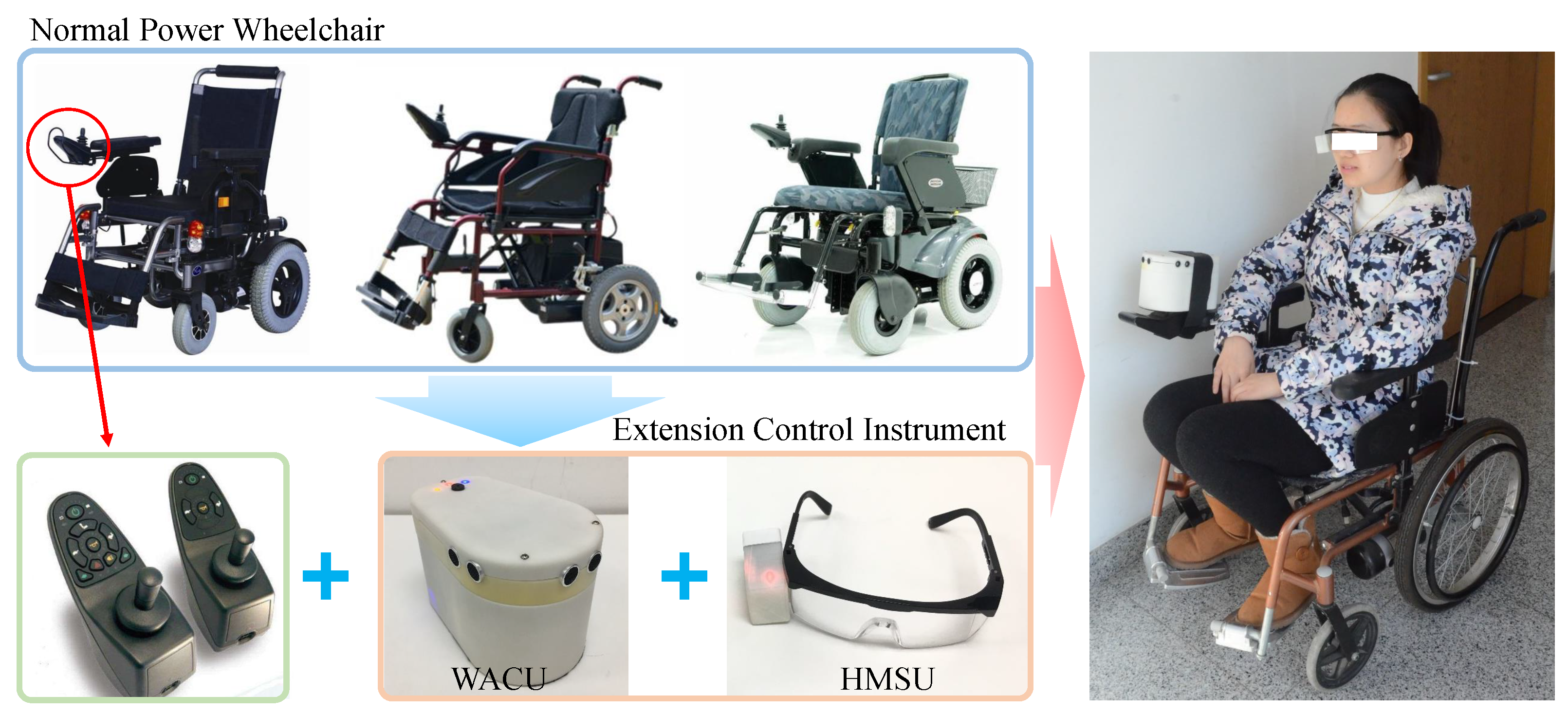
2.1. Principle of System

Figure 1 shows the composition of the extension control instrument for the power wheelchair, actual installation, and application case. The device comprises the Head Motion Sensing Unit (HMSU) and the Wheelchair Assistance Control Unit (WACU). The HMSU is used to accurately detect the head motion posture in real time, and the WACU is used to achieve the precise operation of the joystick to control the wheelchair motion.
The workflow for the novel ECIW is illustrated below. Prior to use, the WACU is attached to the joystick position of a normal power wheelchair using a detachable Velcro sling by ensuring that the hand joystick is inserted into the lower manipulator operating space of the WACU. Then, the subject wears glasses with the HMSU installed. At the same time, the power switches of the HMSU and WACU turn on to start the system and automatically calibrate. The two servos in the WACU return to their initial position, and the hand joystick is in a state of no force. The posture measurement sensor inside the HMSU will determine the current posture of the user’s head as the initial position of 0° and use this as a benchmark to measure the movement posture changes. The collected attitude data are sent to the controller in the WACU via Bluetooth wireless communication after Kalman filtering, and the onboard controller will calculate the direction and displacement of the push rod. Firstly, the WACU actuates the direction selection servo to induce a rotation in the rod-pushing mechanism, corresponding to the desired angle. Subsequently, the rod-pushing servo actuates the gear-rack mechanism, resulting in a deflection of the joystick. This deflection triggers the wheelchair to maneuver in the predetermined direction.
The activation and deactivation procedures for the device’s motion control system are as follows: If the user maintains an upright head position, with an angle less than the predetermined one (6 degrees) for a duration of 15 s, the wheelchair’s motion controller enters a paused state. In this state, normal head movements will not trigger the electric wheelchair to move. To reactivate the motion state, the user would need to tilt their head more than 30 degrees lower. This design ensures that the user can comfortably engage in other activities without unintentionally activating the wheelchair’s movement. Additionally, a beep sound is produced whenever the mode of the wheelchair is changed, providing auditory feedback to the user.
During the movement of the wheelchair, if ultrasonic ranging sensors in the WACU detect that it is close to an obstacle, it will directly interrupt the current movement and slow down and then send a command to the HMSU. A buzzer will sound an alarm to remind the user to change direction in advance to avoid the obstacle. This paper aims to easily modify a common power wheelchair with the designed ECIW to achieve head control of the wheelchair for better interaction with people.

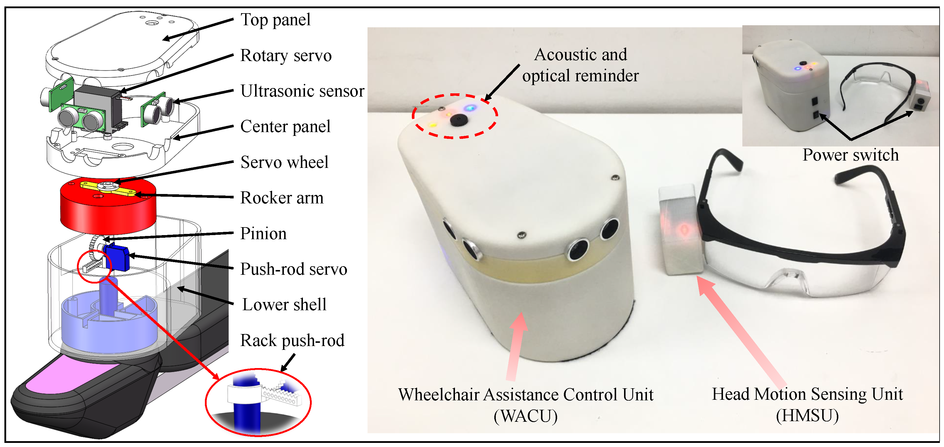
2.2. Mechanical Design

The HMSU is attached to the side of the glasses by adhesive, and the electronic system is highly integrated into a small rectangular structure (49 × 29 × 34 mm in length, width, and height) with a weight of only 20 g. The WACU is attached to the hand joystick of the power wheelchair so that the joystick is precisely in a 2-degree-of-freedom control mechanism, as shown in Figure 2. Although there are some differences in the joystick size of the different power wheelchair controllers, the control principles still have something in common. They all consist of two mutually perpendicular potentiometers with the joystick moving within a defined sphere. Most power wheelchairs change the voltage at the input by changing the access resistance of the joystick potentiometer, which in turn controls the motor rotation. In order to manipulate the joystick, an inner and outer nested 2-degree-of-freedom actuator structure was designed to transform the three-dimensional motion of the joystick into two-dimensional motion, which is further decomposed into rotational and linear movements.
The 2-degree-of-freedom manipulation mechanism of WACU consists of a main body housing and an internal rotating structure. The drive servo of the rotating structure is installed on the middle support plate, whose rudder disk screws to the joystick arm and is fixed to the cylindrical rotating structure, which can drive the downstream structure to rotate around the cylindrical spindle. The inner wall of the rotating structure is fixed with a push rod drive servo, whose rudder disk is connected with a gear, and the pusher handle is designed as a rack. The gears and rack mesh drive to produce a linear reciprocating motion of the push-pull rod. The joystick rotates to the trigger position under the action of the push rod, which in turn controls the wheelchair motion. When the push rod drives the tiller to reverse the rotation, the joystick returns to the original position driven by the return spring of the potentiometer, and the wheelchair terminates the current motion. The direction selection servo model is DSSERVO20, with a rotating speed of 0.16 s/60° and a torque of 18 kg-cm under a 5 V power supply. It can achieve high-precision 360° rotation control. The push rod servo model is MKSHV75K-R, with a rotating speed of 0.21 s/60° and a torque of 1.4 kg-cm under a 3.7 V power supply. The rotation of the rotating structure combined with the back-and-forth movement of the pusher can complete the operation of the joystick instead of manual operation.

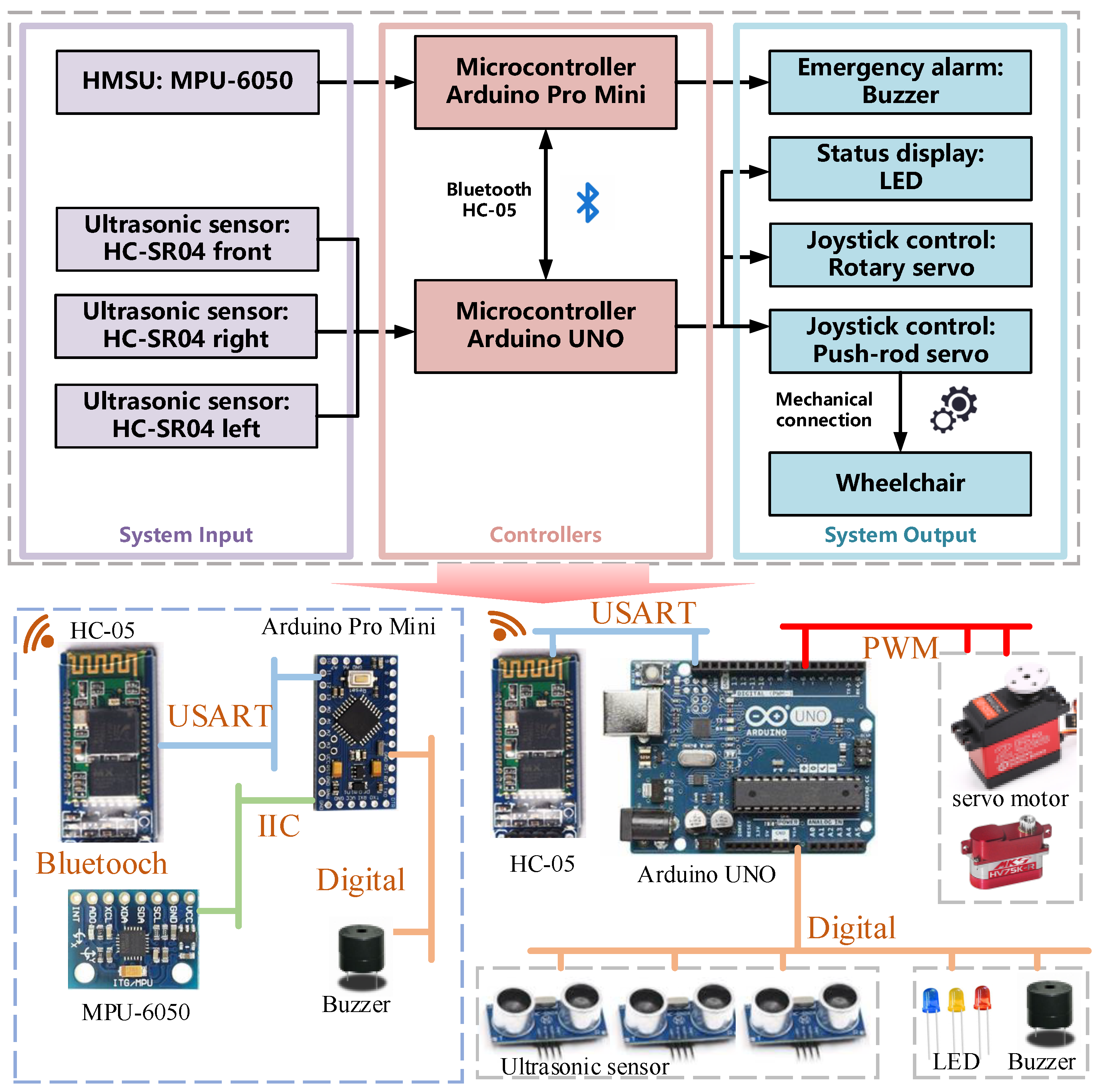
2.3. Hardware of Control System

The hardware composition and architecture of the power wheelchair extension control instrument are shown in Figure 3. The Arduino UNO is the main controller, powered by a lithium battery with a voltage of 7.4 V and a capacity of 1000 mAh. A color LED for power supply and information indication is installed on the housing. The HC-05 Bluetooth module connected to the Arduino UNO wirelessly receives the wheelchair motion control commands from the HMSU by calculating the head posture data. Subsequently, the Arduino UNO drives two servos that use a clever 2-degree-of-freedom joystick control structure to push the lever on the power wheelchair remote control to rotate and control the wheelchair movement. Inside the WACU, three HC-SR04 ultrasonic ranging sensors are embedded in the housing, arranged in the front, left, and right directions. An audible and visual signal prompt will be triggered when the ultrasonic ranging sensor detects a short-range obstacle.
The HMSU is powered by a 7.4 V, 200 mAh Li-ion battery and has an integrated Six-axis attitude sensor (MPU6050) for detecting motion status information. The Arduino Pro Mini microcontroller acts as the control center of the HMSU for onboard data reading and calculation. It builds a wireless communication link with the WACU through the HC-05 Bluetooth module. When the ultrasonic distance measurement module of the ECIW detects being too close to an obstacle or an audible system fault, the active buzzer installed on both the back end of the HMSU and the upper panel of the WACU will sound an alarm to warn the user and people around.
The MPU-6050 is an integrated six-axis motion processing component from InvenSense that incorporates a three-axis gyroscope and three-axis accelerometer, an IIC interface for connecting to external magnetic sensors, and a DMP (Digital Motion Processor) hardware acceleration engine. The HMSU can use the MPU-6050 to obtain information about the user’s head motion posture and use this information to control the wheelchair movement in the subsequent system [18]. The parameters of the system are shown in Table 1.

3. Modeling and Sensing of Head Motion Posture

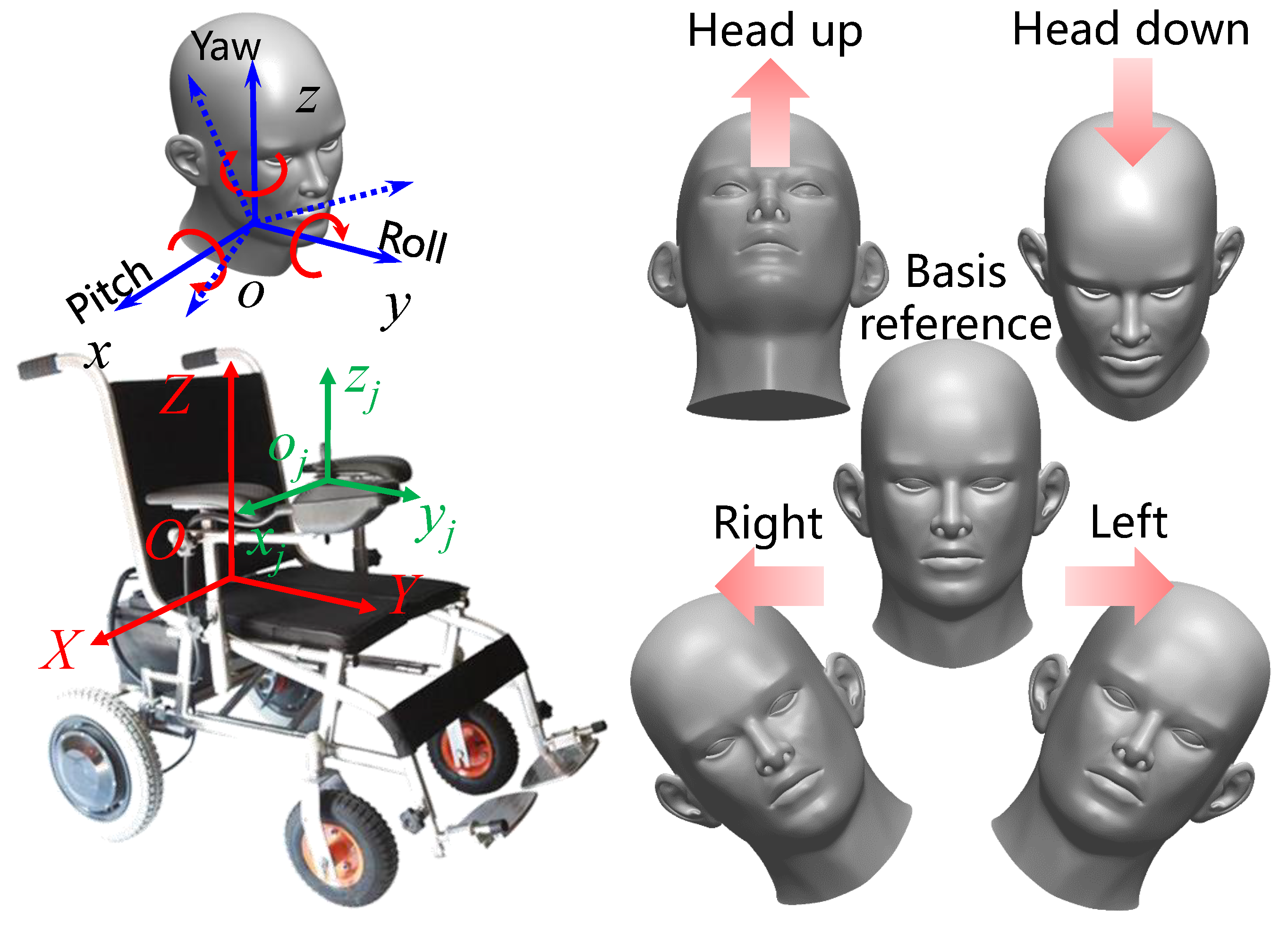
3.1. Head Kinematics

To precisely define the head motion posture, a head–wheelchair dual Cartesian coordinate system is established in this paper, which follows the right-hand rule, as shown in Figure 4. The origin of the head-following coordinate system o x y z is determined at the center of the head–neck connection, with the z-axis coinciding with the central symmetry axis of the head, the y-axis orthogonal to the axis in the symmetry plane of the head, and the x-axis perpendicular to the symmetry plane to the right. The origin of the wheelchair fixed coordinate system O X Y Z is fixed in the symmetry plane at the bottom of the wheelchair seat, with the positive right X-axis, the positive front Y-axis, and the positive top Z-axis. Euler angles describe the head posture in terms of the deflection of the head-following coordinate system relative to the wheelchair fixed coordinate system, where the roll angle is denoted by φ , the pitch angle is denoted by θ , and the yaw angle is denoted by ψ . To describe the joystick manipulation, a joystick coordinate system o j x j y j z j is established at the center of the joystick, with the origin fixed at the base of the joystick and the other three axes parallel to the O X Y Z axes.
The IMU in the HMSU can be used to obtain the triaxial acceleration a x , a y , a z and the triaxial angular velocity ω x , ω y , ω z of the head motion, and the sampling interval of the IMU is set to d t . The Euler angles of the head pose can be calculated using the collected triaxial acceleration a x , a y , a z of x , y , z . The procedure is as follows: When the accelerometer is placed horizontally, i.e., the axis of the head-following coordinate system is parallel to the axis of the wheelchair fixed coordinate system, the reading of the accelerometer is ( 0 , 0 , g ) , where g is the gravitational acceleration. When the head is rotated in a certain attitude, the gravitational acceleration produces a corresponding component in the three axes of the accelerometer, which is essentially the coordinates ( 0 , 0 , g ) of the initial head-following coordinate system in the updated head-following coordinate system.
The rotation of the head is realized by three rotations in X Y Z order, and the corresponding rotation matrices are M x , M y , M z , respectively, with the following equations.
M x = 1 0 0 0 cos φ acc sin φ acc 0 sin φ acc cos φ acc
M y = cos θ acc 0 sin θ acc 0 1 0 sin θ acc 0 cos θ acc
M z = cos ψ acc sin ψ acc 0 sin ψ acc cos ψ acc 0 0 0 1
a x a y a z = M x · M y · M z · 0 0 g = sin θ acc cos θ acc · sin φ acc cos θ acc · cos φ acc · g
where φ a c c is the roll angle measured by the accelerometer and θ a c c is the pitch angle measured by the accelerometer.
Solving the above equations yields the roll and pitch angles as
φ acc = arctan ( a y a z 180 ) π θ acc = arctan ( a x a y 2 + a z 2 180 ) π
Since the plane of rotation of the yaw is mutually perpendicular to gravity, the projection of gravity in the yaw plane measured by the accelerometer is 0. That is, the value measured by the accelerometer is constant no matter what yaw is. Accelerometers cannot directly measure yaw. Therefore, in practical applications, accelerometers are often used in combination with other sensors such as gyroscopes or magnetometers to provide more accurate poses.
The attitude Euler angle of the head can also be calculated using the x , y , z angular velocities ω x , ω y , ω z collected by the gyroscope. The specific calculation procedure is as follows.
θ gyro = 0 t ω x d t + ω x 0 φ gyro = 0 t ω y d t + ω y 0 ψ gyro = 0 t ω z d t + ω z 0
where θ gyro , φ gyro , ψ gyro are the pitch, roll, and yaw of the head pose and ω x 0 , ω y 0 , ω z 0 are the angular velocities of the x-, y-, and z-axes in the initial state, which are generally 0.
The purpose of a gyroscope is to accurately measure angular velocity and reduce noise when external forces impinge on the system. However, the calculation error in the integration factor accumulates over time, and there is a drift in the measured value, causing the system to often not return to zero even when it is back at the origin. Therefore, the gyroscope values are only reliable in the short term. Due to the MEMS structure of the accelerometer, it is sensitive to vibration when external forces are present. Because of the lack of an integration link, the results do not drift over time, and the accelerometer can be used for long periods. Still, the accelerometer cannot calculate the yaw angle [18]. Thus, in practical applications, some processing methods, such as complementary and Kalman filtering, are generally used to combine the data obtained from accelerometer and gyroscope measurements to provide more accurate poses.
Since the accelerometer can only obtain the roll and pitch angles, the yaw angle obtained from the gyroscope measurement is relatively inaccurate because the yaw angle rotates along an axis perpendicular to gravity. Therefore, in this system, the roll and pitch angles are chosen to control the movement of the wheelchair.
The direction and velocity of the actual motion of the wheelchair are dependent on the movement of the rocker and the distance relative to the rocker base, i.e., on the coordinate ( x j , y j , z j ) of the contact point between the push rod and the rocker in the joystick coordinate system, where z j is a constant h.
The mapping relationship between the coordinates ( x j , y j , z j ) and the roll and pitch angles can be set as follows.
x j y j z j = φ φ max 0 0 0 θ θ max 0 0 0 1 L x max L y max h
where L x max and L y max are the maximum displacement of the push rod in the x j and y j .
α = arctan ( y j x j ) L = x j 2 + y j 2
where α is the control amount of the direction selector servo and L is the control amount of the push rod servo. Therefore, the head angle and the speed of the wheelchair have a nonlinear relationship. This design ensures the wheelchair’s flexibility during low-speed starts and provides a better handling experience. In addition, the head angle detection has a dead zone range of 6 degrees, within which the servo is not triggered.

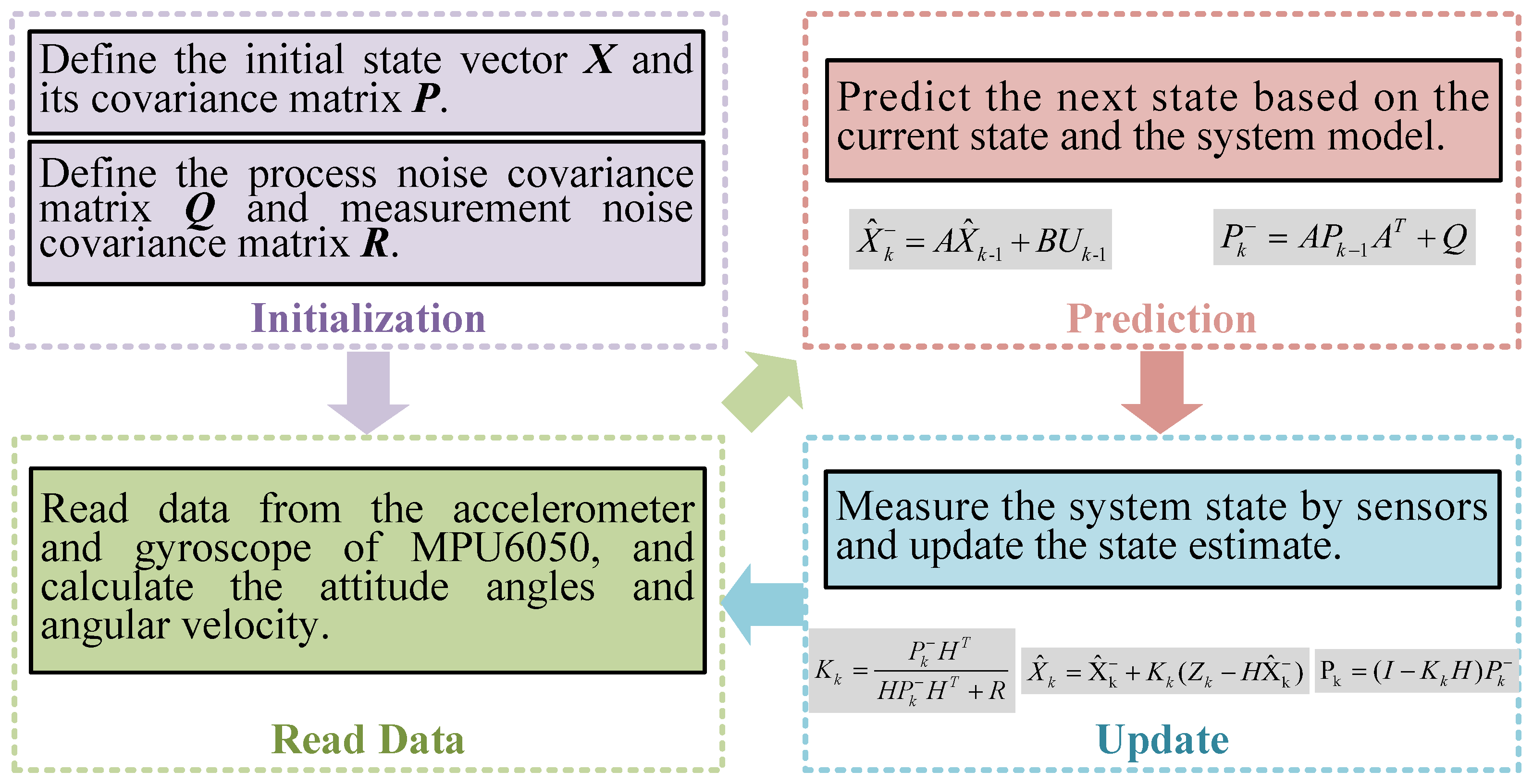
3.2. Kalman Filtering for Motion Sensing

The key to accurate head movement detection is to obtain accurate head posture angle changes. Due to the measurement error and noise during IMU measurement, the roll and pitch angles obtained from the measurement need to be processed using filters for better measurement results. Commonly used filters are complementary filtering and Kalman filtering.
The basic idea of complementary filtering is to weigh the data from different sensors and average them, where the weights can be adaptively adjusted according to the characteristics of each sensor and the measurement noise. Regarding attitude angle correction obtained from IMU measurements, complementary filtering usually processes the accelerometer and gyroscope data separately and their weighted averages to obtain attitude estimation results. The main idea of Kalman filtering is to represent the state of the system as a vector and to update the estimate of the state vector at each step. Although the Kalman filter is much more computationally intensive and slightly less real-time than the complementary filter, its robustness and accuracy are better than those of the complementary filter [19]. Therefore, this system uses Kalman filter processing in the filtering algorithm. The state space equations of the system are as follows.
X k = A K k 1 + B K k 1 + ω k 1 Z k = H X k + V k
where X k 1 is the system state vector and A is the state transfer matrix of the effect of the system state X k 1 on system state X k . B is the input matrix of the control vector U to the state vector X . H is the observation matrix and Z is the system output vector. ω k 1 is the process noise, usually assumed to be zero-mean Gaussian white noise, whose covariance matrix is represented by the following equation P ( ω ) N ( 0 , Q k ) . V k is the measurement noise, again assumed to be zero-mean Gaussian white noise, whose covariance matrix is given by the following equation P ( V ) N ( 0 , R k ) . The process noise ω k 1 and measurement noise V k in the state equation are indeterminable, which represent the uncertainty and random perturbations in the state transfer process and observation process.
Kalman filtering uses the state equation and observation equation to estimate the state of the system by modeling the process noise and observation noise and performs state prediction and updates to obtain the best possible estimate of the state vector of the system. The actual filtering process is as follows [20,21].
A priori estimation of the system state vector is performed:
X ^ k = A X ^ k 1 + BU k 1
where X includes the angle ( x 1 ) and the angular velocity ( x 2 ) , i.e. X k = x 1 x 2 . The state transfer matrix A and the input matrix B can be derived from the state equations.
We calculate the prior error covariance matrix. A priori estimation of the system state vector is performed:
P k = AP k 1 A T + Q
where P is the state covariance matrix and the initial value P 0 needs to be set before the calculation. Q is the process error covariance matrix, which is specified as Q = cov ( x 1 , x 1 ) cov ( x 1 , x 2 ) cov ( x 2 , x 1 ) cov ( x 2 , x 2 ) . Clearly, the covariance between the angle measured by the accelerometer and the angular velocity measured by the gyroscope is zero. Therefore, the process error covariance matrix is Q = cov ( x 1 , x 1 ) 0 0 cov ( x 2 , x 2 ) , where the angular noise covariance cov ( x 1 , x 1 ) is set to 0.001 and the angular velocity noise covariance cov ( x 2 , x 2 ) is set to 0.003.
We calculate the Kalman gain.
K k = P k H T HP k H T + R
where the output matrix H can be derived from Z k = HX k + V k . The posteriori estimation of the system state vector.
X ^ k = X ^ k + K k ( Z k H X ^ k )
where X ^ k is the best estimate of the system state obtained by Kalman filtering. Update the error covariance matrix.
P k = ( I K k H ) P k
where I is the unit matrix.
The Kalman filtering process is a total of five steps, and after several iterations, the resulting X ^ k can be considered as the pose Euler angle (pitch and roll angle) of the user’s head, as show in Figure 5.

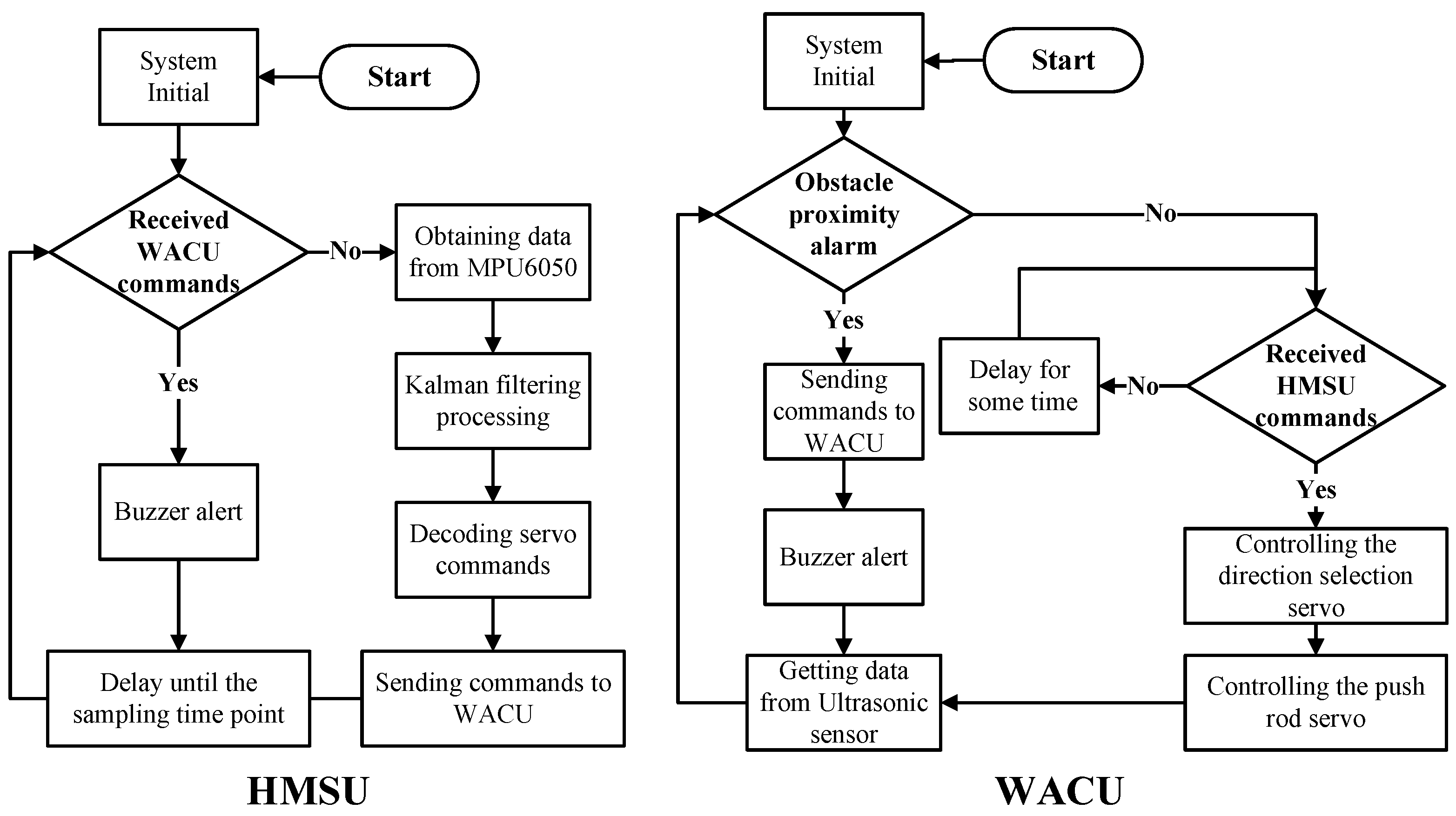
3.3. The Maneuvering Strategy of the Wheelchair

When users use a normal power wheelchair, the commonly used directional commands can be simplified to forward, backward, front left, front right, back left, back right, home left, home right, and stop for nine commands. In addition to the directional commands, there is also the adjustment of speed size. To ensure accurate control and user safety, at least five cases (forward, backward, left turn, right turn, and stop) need to be considered for the ECIW. The other four cases can be achieved by superimposing different cases with corresponding changes in the rotation angle of the joystick.
Since the MPU6050 lacks a magnetometer, the yaw angle measured by the gyroscope is prone to large errors during long runs, while the accelerometer cannot measure the heading angle. Therefore, the system’s left-turn and right-turn recognition attitude is head left-right offset rather than left-right rotation. According to the attitude analysis of forward, backward, left turn, right turn, and stop, it is found that only the pitch angle (forward, backward) and roll angle (left turn, right turn) in the attitude angle are needed in the process of use so that the yaw angle, which is easy to be measured as unstable, is avoided. The stability of the head attitude recognition is ensured. The workflow of the whole system is shown in Figure 6.
Three ultrasonic ranging sensors are mounted in the front, left, and right directions of the WACU. During the driving process, the system will adjust the wheelchair movement command in real time according to the distance of obstacles measured by the ultrasonic ranging sensor. At the same time, the system will alert the user to avoid obstacles through buzzers on the WACU and HMSU with different frequencies according to the distance. The detection range of the ultrasonic sensor is set between 2 cm and 4 m. The alarm is triggered when an object is detected within a distance of 3 m. This strategy ensures that the wheelchair maintains a safe distance of at least 1 m from any detected obstacle, thereby preventing abrupt stops and ensuring the safety of the user.

4. Experiments and Results

4.1. Experiment Settings

The experimental steps for the detection of head motion posture are as follows: (1) the subject wears the HMSU; (2) the sensor is calibrated; (3) the head motion pattern and angle are determined; and (4) the data detected by the inertial sensor are uploaded to the PC in real time using the wireless serial port for analysis.
The manned experiment of the power wheelchair with the installation prototype system was conducted on relatively flat ground and open space. The model of the power wheelchair used in the experiment is HUWEISHEN XFG-205, and its basic performance parameters are shown in Table 2. We fasten the WACU to the wheelchair remote control with the magic strap, ensuring the joystick is inserted into the WACU’s mounting hole.

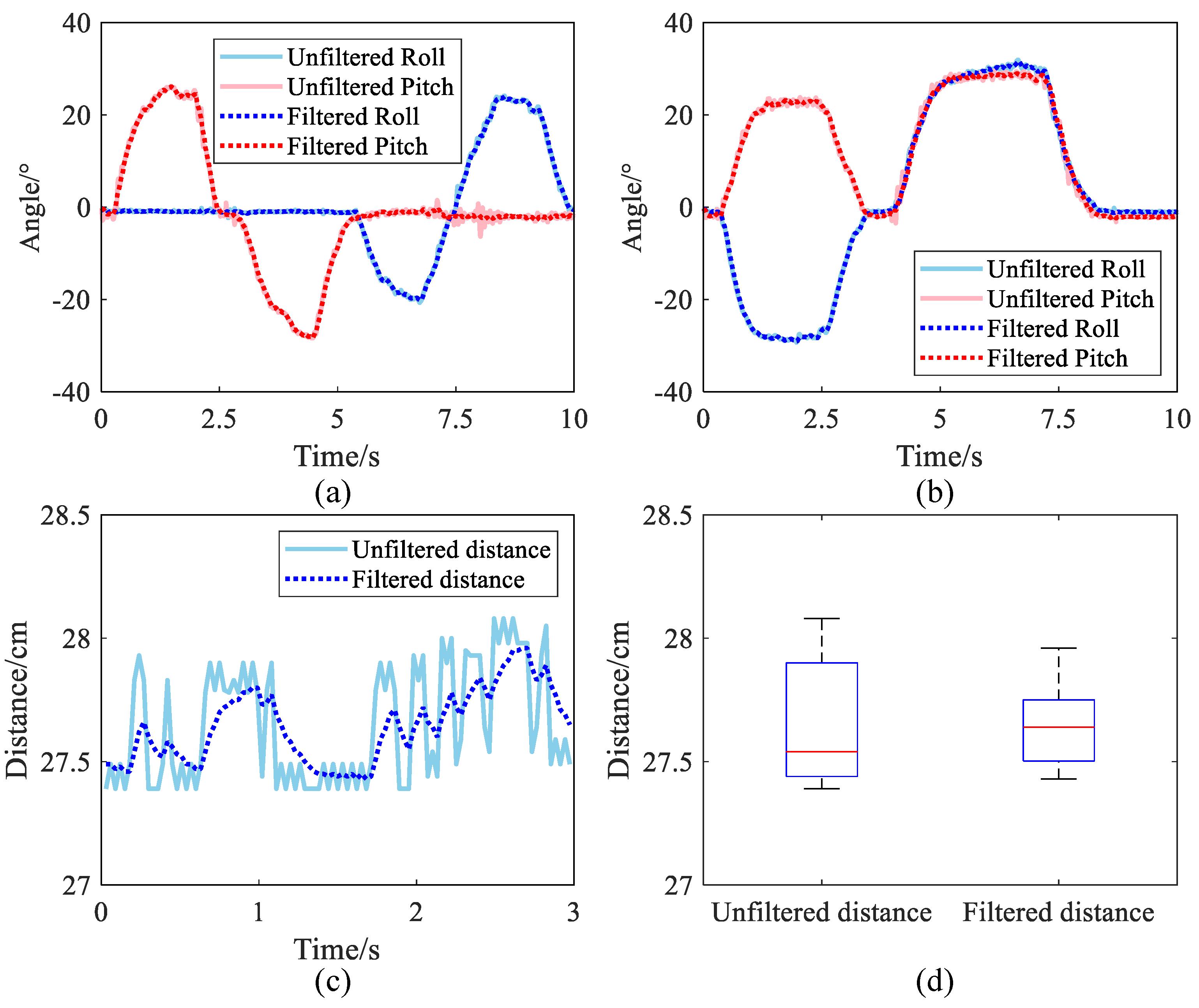
4.2. Analysis of Kalman Filtering Results

The accurate measurement of head posture is the key to the operation of the system. In this paper, Kalman filtering is performed on the data obtained from MPU6050. Subjects performed two rounds of tests, the first time to make backward, forward, left, and right actions in turn and record the changes in pitch and roll angles before and after filtering, as shown in Figure 7a, and the second time to make left-forward and right-forward actions in turn and record the changes in pitch and roll angles before and after filtering, as shown in Figure 7b. Comparing the waveforms before and after filtering, it is obvious that the angle change data after filtering are more stable and smoother than the angle change data before filtering, and the waveform burr is obviously reduced, which proves that the filtering effect is excellent.
In this system, the obstacle avoidance and distance measurement module is the ultrasonic ranging sensor HC-SR04, whose measurement range is 2 cm–400 cm. In order to improve the stability and smoothness of the distance measurement module, the distance returned by the ultrasonic ranging sensor is also processed by Kalman filtering. The ultrasonic ranging sensor and obstacle are fixed separately to test the filtering effect. Ideally, the distance measured by ultrasonic waves should be a fixed value. The data before and after Kalman filtering are plotted in Figure 7c. A comparison shows that the smoothness of the filtered data is much better than that of the unfiltered data. Based on the box plot of the two sets of data in Figure 7d, it can be more intuitively concluded that the Kalman-filtered distance data have fewer outliers and the measured data have less fluctuation.

4.3. Analysis of Head Posture Detection

In this study, a series of experiments to evaluate the performance of the head component of the system were conducted, specifically its ability to detect head postures and execute corresponding commands. The experimental protocol was designed as follows: Two subjects volunteered to participate in the study. They were equipped with the head device and instructed to initiate the system while maintaining an upright head posture. Subsequently, they were asked to perform a series of head movements including tilting forward, backward, left, and right. Each movement was repeated 50 times, resulting in a total of 200 tests. During these tests, the system’s responses, in terms of recognized commands and response times, were diligently recorded for further analysis. The data are presented in Table 3. It was observed that the system recognized two additional instances of right tilt and two fewer instances of left tilt than expected.
The experimental results reveal a discrepancy in the number of right and left tilts, deviating from theoretical values by two counts. This discrepancy is attributed to an error in the program’s angle recognition when the left tilt exceeds 90°, causing it to be misinterpreted as a right tilt. Notably, this issue does not affect the forward and backward tilts, resulting in accurate recognition of these movements. Upon rectifying this error, the system demonstrated a high degree of accuracy in identifying the user’s head posture and executing corresponding instructions, thereby fulfilling basic control requirements. This finding underscores the system’s potential for practical application.

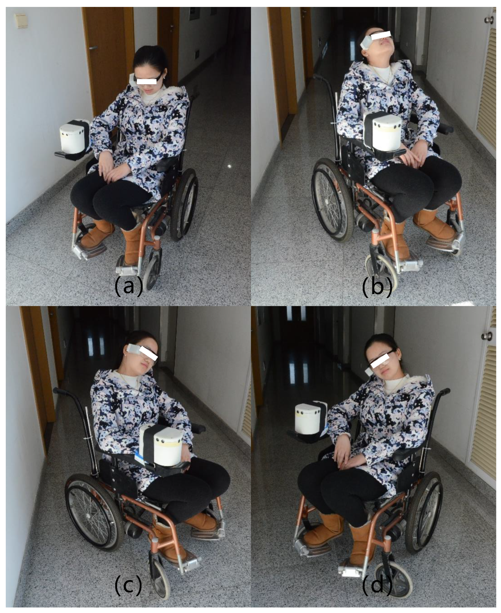
4.4. Prototyping Testing

The experimental protocol for the prototyping test is delineated as follows: Two healthy volunteers consented to partake in the study. The participants wore glasses with HMSUs fixed and sat on powered wheelchairs with WACUs installed. The testing environment was an indoor setting with a marble flooring surface. Each participant was instructed to navigate a predetermined route within the testing field. Additionally, they were required to execute three sets of pre-defined motion control commands at a specified location. These commands encompass head elevation, head depression, and lateral head tilts to both sides.
After the subject made a head movement, the power wheelchair could respond quickly, with an average response time of less than 2 s, meeting the needs of daily use, as shown in Figure 8. The response time is variable by adjusting the parameters of the servo controller. However, the decision to set the average response time to 2 s was made with the comfort of wheelchair users in mind. As the primary sensory organs of humans are located in the head, rapid movements can easily cause discomfort due to the inertia that brings additional movement to the head. In addition, the response time of the brake is significantly shorter than that of the motion command. After the subject made the head-down, head-up, left-tilt, and right-tilt movements, the electric wheelchair made accurate responses, which were, respectively, forward, backward, left-turn, and right-turn. Both subjects positively evaluated the experiment, noting that the wheelchair’s movement feedback was timely and that the device’s weight did not cause significant fatigue, thus deeming it usable.

5. Limitations and Future Work

This study acknowledges several limitations concerning experimental validation. Firstly, the sample size of the subjects was limited, and all participants were healthy individuals. This demographic may not accurately represent the broader population of individuals with limb mobility impairments. Secondly, despite the device’s design for multi-wheelchair compatibility, the experiment was conducted using only one type of wheelchair, leaving its adaptability unverified. Furthermore, the experimental environment was a flat surface, which does not reflect the complex terrains often encountered by power wheelchair users in real-world scenarios.
To address these limitations, future work will involve more comprehensive experimental validation. We plan to include a more diverse test group, encompassing actual patients and wheelchair users, and will actively seek their feedback. Additionally, we aim to test our device on a minimum of three different wheelchair models to better assess its adaptability. As for the experimental sites, we will differentiate between indoor and outdoor testing scenarios. Indoor tests will be conducted in a realistic home environment, while outdoor tests will be designed in a field spanning at least 10,000 square meters. This approach will ensure a more robust and comprehensive evaluation of our device’s performance and usability.

6. Conclusions

This research delineates the conception and efficacious execution of an innovative extension control instrument for power wheelchairs, utilizing Kalman filter technology to interpret and convert head movements into navigational directives. The innovative control system encompasses a Head Motion Sensing Unit (HMSU), fortified with an inertial measurement module that discerns and processes alterations in head attitude to derive accurate Euler angles via Kalman filtering. The Wheelchair Assistance Control Unit (WACU) interfaces with the pre-existing controller of the wheelchair, supplanting the manual joystick control with a two-degree-of-freedom servo mechanism connected to a pinion-and-rack push rod configuration. This setup empowers users to manipulate the wheelchair’s movements merely by adjusting their head posture. Additionally, the system incorporates an obstacle detection feature through ultrasonic ranging sensors affixed to the WACU, facilitating real-time environmental monitoring in the front, left, and right directions, thereby enabling a fundamental level of obstacle evasion. Prototype testing substantiated that the Kalman filter-based head motion detection is both responsive and precise in recognizing intended user actions and subsequently directing the wheelchair correspondingly. Experiments validated the efficacy of the developed device, demonstrating its ability to reliably and swiftly map head movements to wheelchair commands, thereby ensuring enhanced mobility and usability. In conclusion, this research successfully engineered an adaptable and intuitive control system for power wheelchairs.

Author Contributions

Y.Z. and Y.M. conceived this paper. Y.Z. and J.H. designed the structure of the instrument and developed the prototype. Z.Y., S.J. and J.H. planned the experiments. Z.Y., S.J. and X.T. conducted the experiments and simulations. The results were analyzed by all authors. The manuscript was written by Y.Z. and reviewed by all authors. All authors have read and agreed to the published version of the manuscript.

Funding

This research was funded in part by the National Natural Science Foundation of China under Grant 52205299 and in part by the China Postdoctoral Science Foundation under Grant 2022M710304.

Institutional Review Board Statement

Not applicable.

Informed Consent Statement

Not applicable.

Data Availability Statement

Data are contained within the article.

Acknowledgments

The authors thank Zheng Zhao and BIO Innovation (Tianjin, China) Technology Co., Ltd., for the experimental advice and technical support. This study is also supported by the College Students’ Innovative Entrepreneurial Training Plan Program and the Tianjin Project Plus Team Key Training Project.

Conflicts of Interest

The authors declare no conflicts of interest.

References

  1. World Health Organization; United Nations Children’s Fund. Global Report on Assistive Technology; World Health Organization: Geneva, Switzerland, 2022. [Google Scholar]
  2. Wieczorek, B.; Kukla, M. Biomechanical Relationships Between Manual Wheelchair Steering and the Position of the Human Body’s Center of Gravity. J. Biomech. Eng. 2020, 142, 081006. [Google Scholar] [CrossRef] [PubMed]
  3. Kader, M.A.; Alam, M.E.; Jahan, N.; Bhuiyan, M.A.B.; Alam, M.S.; Sultana, Z. Design and implementation of a head motion-controlled semi-autonomous wheelchair for quadriplegic patients based on 3-axis accelerometer. In Proceedings of the 2019 22nd International Conference on Computer and Information Technology (ICCIT), Dhaka, Bangladesh, 18–20 December 2019; IEEE: Piscataway, NJ, USA, 2019; pp. 1–6. [Google Scholar]
  4. Xiong, M.; Hotter, R.; Nadin, D.; Patel, J.; Tartakovsky, S.; Wang, Y.; Patel, H.; Axon, C.; Bosiljevac, H.; Brandenberger, A.; et al. A low-cost, semi-autonomous wheelchair controlled by motor imagery and jaw muscle activation. In Proceedings of the 2019 IEEE International Conference on Systems, Man and Cybernetics (SMC), Bari, Italy, 6–9 October 2019; IEEE: Piscataway, NJ, USA, 2019; pp. 2180–2185. [Google Scholar]
  5. Subramanian, M.; Songur, N.; Adjei, D.; Orlov, P.; Faisal, A.A. A. Eye Drive: Gaze-based semi-autonomous wheelchair interface. In Proceedings of the 2019 41st Annual International Conference of the IEEE Engineering in Medicine and Biology Society (EMBC), Berlin, Germany, 23–27 July 2019; IEEE: Piscataway, NJ, USA, 2019; pp. 5967–5970. [Google Scholar]
  6. Simpson, R.C.; Levine, S.P. Voice control of a powered wheelchair. IEEE Trans. Neural Syst. Rehabil. Eng. 2002, 10, 122–125. [Google Scholar] [CrossRef] [PubMed]
  7. Lu, T. A motion control method of intelligent wheelchair based on hand gesture recognition. In Proceedings of the 2013 IEEE 8th Conference on Industrial Electronics and Applications (ICIEA), Melbourne, Australia, 19–21 June 2013; IEEE: Piscataway, NJ, USA, 2013; pp. 957–962. [Google Scholar]
  8. Kundu, A.S.; Mazumder, O.; Lenka, P.K.; Bhaumik, S. Hand gesture recognition based omnidirectional wheelchair control using IMU and EMG sensors. J. Intell. Robot. Syst. 2018, 91, 529–541. [Google Scholar] [CrossRef]
  9. Wanluk, N.; Visitsattapongse, S.; Juhong, A.; Pintavirooj, C. Smart wheelchair based on eye tracking. In Proceedings of the 2016 9th Biomedical Engineering International Conference (BMEiCON), Laung Prabang, Laos, 7–9 December 2016; IEEE: Piscataway, NJ, USA, 2016; pp. 1–4. [Google Scholar]
  10. Zgallai, W.; Brown, J.T.; Ibrahim, A.; Mahmood, F.; Mohammad, K.; Khalfan, M.; Mohammed, M.; Salem, M.; Hamood, N. Deep learning AI application to an EEG driven BCI smart wheelchair. In Proceedings of the 2019 Advances in Science and Engineering Technology International Conferences (ASET), Dubai, United Arab Emirates, 26 March–10 April 2019; IEEE: Piscataway, NJ, USA, 2019; pp. 1–5. [Google Scholar]
  11. Mirza, I.A.; Tripathy, A.; Chopra, S.; D’Sa, M.; Rajagopalan, K.; D’Souza, A.; Sharma, N. Mind-controlled wheelchair using an EEG headset and arduino microcontroller. In Proceedings of the 2015 International Conference on Technologies for Sustainable Development (ICTSD), Mumbai, India, 4–6 February 2015; IEEE: Piscataway, NJ, USA, 2015; pp. 1–5. [Google Scholar]
  12. Kupetz, D.; Wentzell, S.; BuSha, B. Head motion controlled power wheelchair. In Proceedings of the 2010 IEEE 36th Annual Northeast Bioengineering Conference (nebec), New York, NY, USA, 26–28 March 2010; IEEE: Piscataway, NJ, USA, 2010; pp. 1–2. [Google Scholar]
  13. Iskanderani, A.I.; Tamim, F.R.; Rana, M.M.; Ahmed, W.; Mehedi, I.M.; Aljohani, A.J.; Latif, A.; Shaikh, S.A.L.; Shorfuzzaman, M.; Akther, F.; et al. Voice Controlled Artificial Intelligent Smart Wheelchair. In Proceedings of the 2020 8th International Conference on Intelligent and Advanced Systems (ICIAS), Kuching, Malaysia, 13–15 July 2021; IEEE: Piscataway, NJ, USA, 2021; pp. 1–5. [Google Scholar]
  14. Kutbi, M.; Du, X.; Chang, Y.; Sun, B.; Agadakos, N.; Li, H.; Hua, G.; Mordohai, P. Usability studies of an egocentric vision-based robotic wheelchair. ACM Trans. Hum.-Robot. Interact. (THRI) 2020, 10, 1–23. [Google Scholar] [CrossRef]
  15. Azraai, M.M.; Yahaya, S.Z.; Chong, I.A.; Soh, Z.C.; Hussain, Z.; Boudville, R. Head gestures based movement control of electric wheelchair for people with tetraplegia. In Proceedings of the 2022 IEEE 12th International Conference on Control System, Computing and Engineering (ICCSCE), Penang, Malaysia, 21–22 October 2022; IEEE: Piscataway, NJ, USA, 2022; pp. 163–167. [Google Scholar]
  16. Gonzalez-Cely, A.X.; Blanco-Diaz, C.F.; Diaz, C.A.; Bastos-Filho, T.F. Roborueda: Python-based GUI to control a wheelchair and monitor user posture. SoftwareX 2023, 24, 101555. [Google Scholar] [CrossRef]
  17. Sebkhi, N.; Bhavsar, A.; Sahadat, N.; Baldwin, J.; Walling, E.; Biniker, A.; Hoefnagel, M.; Tonuzi, G.; Osborne, R.; Anderson, D.V.; et al. Evaluation of a head-tongue controller for power wheelchair driving by people with quadriplegia. IEEE Trans. Biomed. Eng. 2021, 69, 1302–1309. [Google Scholar] [CrossRef] [PubMed]
  18. Ziying, Y.; Hong, G.; Wenhao, J. Design and implementation of a MEMS-based attitude angle measuring system for moving objects. In Proceedings of the 2021 IEEE International Conference on Power, Intelligent Computing and Systems (ICPICS), Shenyang, China, 29–31 July 2021; IEEE: Piscataway, NJ, USA, 2021; pp. 145–149. [Google Scholar]
  19. Gui, P.; Tang, L.; Mukhopadhyay, S. MEMS based IMU for tilting measurement: Comparison of complementary and kalman filter based data fusion. In Proceedings of the 2015 IEEE 10th conference on Industrial Electronics and Applications (ICIEA), Auckland, New Zealand, 15–17 June 2015; IEEE: Piscataway, NJ, USA, 2015; pp. 2004–2009. [Google Scholar]
  20. Welch, G.; Bishop, G. An Introduction to the Kalman Filter; University of North Carolina at Chapel Hill: Chapel Hill, NC, USA, 1995. [Google Scholar]
  21. Chui, C.K.; Chen, G. Kalman Filtering; Springer: Berlin/Heidelberg, Germany, 2017. [Google Scholar]
Figure 1. Common power wheelchair, joystick controller, composition of extension control instrument for power wheelchair, and application case.
Actuators 13 00141 g001
Figure 2. Detailed mechanical structure of extension control instrument for power wheelchair.
Actuators 13 00141 g002
Figure 3. Control system architecture and hardware composition of the ECIW system.
Actuators 13 00141 g003
Figure 4. Coordinate system and typical head movements of a person using a power wheelchair, including natural state, head down, head up, right tilt, and left tilt.
Actuators 13 00141 g004
Figure 5. Kalman filtering schematic.
Actuators 13 00141 g005
Figure 6. System workflow diagram.
Actuators 13 00141 g006
Figure 7. Comparison of head attitude angle before and after Kalman filter and ultrasonic ranging results. (a) Pitch and roll angles during backward, forward, left, and right actions in turn. (b) Pitch and roll angles during left-forward and right-forward actions in turn. (c) Distance data measured by ultrasonic sensor. (d) Comparison of the filtered data and the unfiltered data.
Actuators 13 00141 g007
Figure 8. The test of the control effect of the actual installation of the extended control system for the power wheelchair. (a) Foward. (b) Backward. (c) Turn left. (d) Turn right.
Actuators 13 00141 g008
Table 1. Parameters of the system.
ParametersValue
Mass of WACUAbout 760 g
Mass of HMSU84.2 g (with glasses)
Size of WACU174 × 110 × 120 mm
Size of HMSU64 × 28 × 37 mm
Endurance timeAbout 5 h
Response speed<1 s
Applicable modelPower wheelchairs controlled by hand
Angle accuracyAbout 1°
Table 2. The parameters of the experimental wheelchair.
ParameterValue
Length × width × height95 × 56 × 90 cm
Maximum rate6 km/h
Rated endurance25 km
Vehicle weight13.8 kg
Table 3. Result of head motion detection.
ParameterForwardBackLeftRight
Test times50505050
Recognition times50504852
Disclaimer/Publisher’s Note: The statements, opinions and data contained in all publications are solely those of the individual author(s) and contributor(s) and not of MDPI and/or the editor(s). MDPI and/or the editor(s) disclaim responsibility for any injury to people or property resulting from any ideas, methods, instructions or products referred to in the content.

