Article

Research on Multi-Mode Control of Electro-Hydraulic Variable Displacement Pump Driven by Servo Motor

1
School of Mechanical Engineering, Taiyuan University of Science and Technology, Taiyuan 030024, China
2
Shanxi Key Laboratory of Metallic Materials Forming Theory and Technology, Taiyuan University of Science and Technology, Taiyuan 030024, China
3
State Key Laboratory of Mechanical System and Vibration, Shanghai Jiao Tong University, Shanghai 200240, China
*
Author to whom correspondence should be addressed.
Actuators 2024, 13(5), 190; https://doi.org/10.3390/act13050190
Submission received: 17 April 2024 / Revised: 12 May 2024 / Accepted: 14 May 2024 / Published: 15 May 2024

Abstract

:
The electro-hydraulic power source with an electro-hydraulic variable pump driven by a servo motor is suitable for electrified construction machinery. To achieve better energy efficiency in different working conditions, the multi-mode control scheme was proposed for the electro-hydraulic power source. The control scheme includes pressure control, flow control, and torque control modes. The switching rule among the three control modes was formulated based on the minimum pump pressure. The fuzzy PID controller was designed, and a composite flow regulation strategy was formulated, including the load-sensitive adaptive displacement regulation and servo motor variable speed regulation. The AMESim-Simulink co-simulation model of multi-mode control was established. The test platform was built, and the experimental study was carried out. The results indicate that the fuzzy PID control has a shorter response time and a more stable control effect compared with PID control. Additionally, the composite flow regulation strategy improves the flow regulation range by 36% and reduces the flow overshoot by 20% compared with the load-sensitive adaptive displacement regulation. As the main control valve received an opening step signal, the full flow regulation (7~81 L/min) of the power source took approximately 0.5 s to rise and 0.2 s to fall. The relative error of pressure difference for the main control valve was 0.63%. When receiving the pressure and torque step signal, the pump pressure and pump input torque both took approximately 0.45 s to rise and 0.2 s to fall. The relative errors of pump pressure and torque control were 0.2% and 0.16%, respectively. In the multi-mode control, the electro-hydraulic power source could switch smoothly between flow control mode, pressure control mode, and torque control mode. These results provide a reference for the multi-mode control of an electro-hydraulic power source with an electro-hydraulic variable pump driven by a servo motor.

1. Introduction

An electro-hydraulic power source refers to a power unit composed of an electric motor and a hydraulic pump. The electric motor converts electrical energy into mechanical energy, and the hydraulic pump then converts this mechanical energy into hydraulic energy, and the electro-hydraulic power source provides hydraulic energy to hydraulic actuators (cylinder and motor) to work. As the environment becomes increasingly harsh, construction machinery such as hydraulic excavators and loaders are beginning to use electric motor-driven hydraulic pumps as a power source to replace internal combustion engines and eliminate exhaust emissions. The conventional electro-hydraulic power source consists of a fixed-speed motor that drives a hydraulic pump [1,2]. There are two types of hydraulic pumps: quantitative and variable pumps. Using quantitative pumps as the power source results in significant throttling and overflow losses [3]. To decrease the energy consumption of the hydraulic power source, the recommended approach is to use variable pumps with pressure, flow, or power control as the power source, which can match the output parameters of the hydraulic pump to the load [4,5], but the use of a constant speed drive still results in significant energy loss in the non-working cycle [6]. Moreover, traditional variable-speed control cannot solve the issue of saving energy under conditions of low flow and high pressure. In recent years, the trend toward combinations of variable displacement and variable speed pump drives has become apparent. A variable pump power source driven by a servo motor could fully utilize the motor’s excellent speed performance to reduce energy consumption in the system of small flow by reducing the speed. Additionally, it could achieve a rich set of control functions, making the hydraulic system more flexible and diverse [7,8].
Variable pumps are commonly used in construction machinery to achieve positive flow control, negative flow control, and load-sensitive control functions. This is done to meet the system flow control requirements and reduce energy losses [9,10,11]. When operating under load-sensitive control, the pump pressure always follows the maximum load pressure, resulting in greater energy efficiency. Traditional variable pumps often rely on components such as load-sensing valves, pressure shut-off valves, and power-limiting valves [12,13] to control their function. This would lead to a complex pump structure and limit the control parameters. The advancement of automation technology has led to variable displacement pumps becoming more intelligent. Modern variable displacement pumps now use advanced electronic control systems to replace traditional pressure cut-off valves and power-limiting valves. This simplifies the structure of variable displacement pumps and provides more flexible control functions. As a result, construction machinery could operate more efficiently under various working conditions [14,15]. Ming-Hwei Chu conducted an investigation on a variable displacement axial pump with an electro-hydraulic proportional valve. The aim is to control the pump displacement and design a servo controller to enhance system stability and transient response [16].
Researchers have proposed advanced algorithms and control strategies, such as fuzzy control, sliding mode control, and neural networks, to meet the varied control functions of electro-hydraulic power sources [17,18,19]. These intelligent control algorithms have been studied in construction machinery. However, it is important to maintain a simple structure and reliable performance [20]. PID control is irreplaceable due to its robustness and other characteristics. The parameters of PID control have a significant impact on control accuracy and speed. Therefore, optimizing these parameters could effectively improve system control performance [21]. Fuzzy control enhances a system’s adaptability and robustness by adjusting fuzzy rules and membership functions to accommodate various systems and environmental changes. It also simplifies the complexity of system design by using linguistic variables instead of numerical ones. Therefore, the combination of fuzzy control with PID enables the automatic tuning of PID control parameters based on the actual state of the system and target requirements, achieving precise control over the system [22,23]. Anis [24] proposed a fuzzy proportional-derivative (PD) control scheme for constant power control of hydraulic pumps. The dynamic control effect of this scheme is better than that of PD control. To tackle the issue of switching when multiple control modes are integrated into a hydraulic pump, Cheng Min [25,26] et al. proposed an anti-saturation switching flow/power controller. This controller solves the PID integral saturation problem that occurs during mode switching. The authors also analyzed the stability of mode switching by defining different mode-switching rules and priorities for the multi-mode electro-hydraulic control scheme. Tim-Liang Lin [27] proposed a bivariate load-sensitive system to address the low energy utilization of traditional electric excavators. Lin investigated a graded differential pressure control strategy that can effectively improve control performance and reduce energy consumption. Jong-Hyeok Kim [28] developed a constant-pressure control strategy using a variable-speed motor and a variable pump as the power source to reduce energy consumption under constant-pressure control. This resulted in an efficient system. Weiping Wang [29] proposed an energy-saving control strategy based on electro-hydraulic load sensitivity with variable pump pressure. This strategy reduces pressure loss and improves the efficiency of the electro-hydraulic servo system.
In summary, the electro-hydraulic power source is evolving toward greater energy efficiency, while the control function is shifting toward electronic control. It is worth noting that there are fewer studies on the multi-mode control of flow, pressure, and torque for variable pumps driven by servo motors. This paper proposes a multi-mode control scheme for variable pumps driven by servo motors. Fuzzy PID controllers were designed, the switching rules among control modes were formulated, and AMESim-Simulink soft was used for co-simulation. A test platform was built to verify the feasibility and control performance.

2. System Principle

2.1. System Introduction

Figure 1 shows the variable pump system driven by a servo motor, which includes a servo motor, an electro-hydraulic proportional variable pump, a main control valve (MC-V), various sensors, and a controller. The electro-hydraulic proportional variable pump comprises a pressure control valve (PC-V), a variable cylinder, a damping orifice, and a proportional relief valve (PR-V). The controller receives and processes the signals from multiple sensors, such as load pressure, pump pressure, and pump displacement. Then, the controller outputs the control signals to the main control valve (MC-V), servo motor, and proportional relief valve (PR-V) to control the system pressure and flow rate according to the system’s actual working conditions.
The pressure control valve (PC-V) spool bears the pump pressure on the left side, and the PR-V sets pressure on the right side. The dynamic force balance equation of the spool is the following:
( P C P S ) A 1 F S = m 1 d 2 x 1 d t 2 + b 1 d x 1 d t + k 1 x 1 ,
Δ P 2 = F S A 1 ,
where P C   is the pump pressure, P S is the PR-V set pressure, Δ P 2   is the pressure difference, F S   is the spring preload, A 1   is the spool area, m 1 is the spool mass, b 1 is the viscous damping coefficient, k 1 is the spring stiffness, and x 1 is the spool displacement.
In Figure 1, the PC-V spool is stable when the pressure difference Δ P 2 of the damping hole is equal to the PC-V spring force. If the PR-V set pressure is reduced, the pressure difference Δ P 2 is larger than the PC-V spring force, causing the PC-V spool to move right and the PC-V spring to be compressed. This causes the high-pressure oil from the pump into the rodless chamber of the variable cylinder, causing the variable cylinder piston to move to the left side and the swash plate tilt angle to decrease, which in turn reduces the pump displacement. If the PR-V set pressure increases, the pressure difference Δ P 2 becomes smaller than the PC-V spring force. As a result, the variable cylinder piston moves to the right, and the pump swashplate angle and pump displacement both increase. The dynamic force balance equation of the variable cylinder piston is the following:
P a A 2 F 2 = m 2 d 2 x 2 d t 2 + b 2 d x 2 d t + k 2 x 2 ,
where P a is the rodless chamber pressure, F 2 is the spring preload, m 2 is the variable piston mass, x 2 is the variable piston displacement, b 2 is the viscous damping coefficient, and k 2   is the spring stiffness.

2.2. Multi-Mode Control Strategy

The variable pump system driven by the servo motor in Figure 1 has three control modes: pressure control mode, flow control mode, and torque control mode.

2.2.1. Strategy in Pressure Control Mode

The system working principle in pressure control mode is as follows. The pump pressure P C and load pressure P L are collected and converted into voltage signals by the pressure sensor and transmitted into the controller. Then, the controller outputs the voltage signals to the PR-V, which controls the pump pressure according to the system’s actual working conditions.
In pressure control mode, the controller adjusts the set pressure P PS according to the system’s actual working conditions. If the detected pump pressure from the pressure sensor exceeds the set pressure P PS , the controller reduces the PR-V set pressure. Then, the pump pressure P C ( t ) is reduced until the difference   Δ P 2 between the detected pressure P C ( t ) and the set pressure P PS is in the allowable error range. The detected pump pressure P C ( t ) in the pressure control mode is expressed as follows:
P C ( t ) = P PS ± P er ,
where P PS is the set value of pump pressure in the pressure mode and P er is the allowable error.

2.2.2. Strategy in Flow Control Mode

The output flow rate of the electro-hydraulic power source is regulated by load-sensitive adaptive displacement control (LSAD) and servo-motor variable speed control (SMVS). The composite flow control (LSSM) strategy is developed for the adaptive displacement control (LSAD) and the variable speed control (SMVS).
In flow control mode, the pump pressure and load pressure are collected by the pressure sensor, converted into voltage signals, and transmitted to the controller. The difference between the pump pressure and load pressure, known as the pressure difference Δ P 1 of the main control valve, is the control target of the electro-hydraulic power source. The controller outputs a voltage signal to the proportional relief valve, which determines the pump pressure and achieves the pressure difference Δ P 1 . The relationship between pump pressure and load pressure can be expressed as follows:
P C ( t ) = P L ( t ) + Δ P S ,
where P C ( t ) is the pump pressure, P L is the load pressure, and Δ P S is the set value of the pressure difference for Δ P 1 .
The opening area of the main control valve is proportional to the input voltage signal and expressed as follows:
A 3 = K 3 U 1 + B 3 ,
where A 3 is the main control valve opening area, K 3 is the signal gain, U 1 is the main control valve voltage signal, and B 3 is the offset.
The flow rate through the main control valve is expressed as follows:
Q ( t ) = C q A 3 2 ρ ( P C ( t ) P L ( t ) ) ,
where Q ( t ) is the MC-V flow rate, C q is the flow coefficient, and ρ   is the oil density.
The pump output flow rate is expressed as follows:
Q ( t ) = n ( t ) V g ( t ) η ,
where n ( t ) is the motor speed, V g ( t ) is the pump displacement, and η is the pump volumetric efficiency.
In Equation (7), the MC-V flow rate is proportional to the MC-V opening signal when the pressure difference Δ P 1 is constant. In Equation (8), the pump output flow is proportional to the pump displacement at the constant motor speed and proportional to the motor speed for the constant pump displacement.
The LSSM composite flow regulation strategy is the following:
(1)
The flow voltage signal of MC-V is small, UU1m, the motor runs at an idle speed, and variable pump displacement is adjusted to meet MC-V flow demand;
(2)
The flow voltage signal of MC-V is large, U > U1m, the pump works at maximum displacement, and the motor speed is adjusted to meet MC-V flow demand.
The mathematical model for the LSSM flow regulation strategy is the following:
Q ( t ) = { n min V g ( t ) 1000 , U 1 U 1 m n ( t ) V gmax 1000 , U 1 m < U 1 ,
where n min is the motor idle speed, V gmax   is the maximum pump displacement, and U 1 m is the MC-V opening signal when the motor runs at idle speed and the pump at maximum displacement.

2.2.3. Torque Control Strategy

Torque control technology is used to prevent motor overload. In the torque control mode, the pump pressure set value is calculated according to the torque setting value and the pump displacement V g . Then, the controller outputs a voltage signal to PR-V and regulates the pump pressure through the variable cylinder to ensure that the difference between the pump output torque and the torque setting value is in the allowable error range. The pump mechanical efficiency is assumed to be constant, and the formula of pump torque is as follows:
T S = P C ( t ) V g ( t ) 2 π ,
where T s is the pump torque.

2.2.4. Controller Design

Pressure control, flow control, and torque control are realized by regulating the pump pressure. A fuzzy PID controller was designed for pump pressure feedback control. The fuzzy PID controller consists of a PID controller and a fuzzy controller, and its control principle is shown in Figure 2.
The PID controller model is shown in Equation (11). When the fuzzy PID is running, the deviation e and the deviation change rate ec are the input quantities. Moreover, Δ K p , Δ K i , and Δ K d   are continuously adjusted according to the fuzzy control rules, and the fuzzy PID parameters required for system control are finally obtained. The fuzzy PID parameters are rectified, as shown in Equation (12), and the fuzzy PID control model can be obtained by combining Equations (11) and (12), as shown in Equation (13). After determining the input and output variables of the fuzzy control, the fuzzy sets of the variables are categorized into seven classes, namely {NB (negative large), NM (negative medium), NS (negative small), ZO (medium), PS (positive small), PM (positive medium), and PB (positive large)}, and the fuzzy sets are mapped into intervals of {0 1} by means of the membership function. Usually, the selection of the membership function is chosen by experienced engineers or based on statistics and experience. In this paper, the triangular affiliation function was used. Fuzzy rules are used to describe the relationship between outputs and outputs, and their formulation directly affects the fuzzy control effect; the fuzzy rules are shown in Table 1.
U ( t ) = K P e ( t ) + K i 0 t e ( t ) + K d d e ˙ ( t ) d t ,
{ K p = K p + Δ K p K i = K i + Δ K i K d = K d + Δ K d ,
U ( t ) = ( K p + Δ K p ) e ( t ) + ( K i + Δ K i ) 0 t e ( t ) + ( K d + Δ K d ) d e ˙ ( t ) d t ,
where U ( t ) is the controller output; K p ’, K i ’, K d ’ are the initial parameters of the PID controller; Δ K p , Δ K i , Δ K d are the parameter variations of the fuzzy control outputs; and K p , K i , K d are the parameters after fuzzy PID rectification.
e ( t )   is the pump pressure error, which is expressed as follows:
e ( t ) = P M ( t ) - P C ( t )
P M ( t ) in Equation (14) is the minimum value of pump pressure obtained from the three controls and is expressed as follows:
P M ( t ) = min { P LS ( t ) , P PS ( t ) , P TS ( t ) } ,
where P LS ( t ) is the pump pressure in the flow control mode, P PS ( t ) is the pump pressure in the pressure control mode, and P NS ( t ) is the pump pressure in the torque control mode.
The controller switches modes according to Equation (14). The electro-hydraulic power source switches into the flow control mode when P LS ( t ) is minimum, into the pressure control mode when P PS ( t ) is minimum, and into the torque control mode when P TS ( t ) is minimum. The multi-mode control flowchart is shown in Figure 3.

3. Simulation Analysis

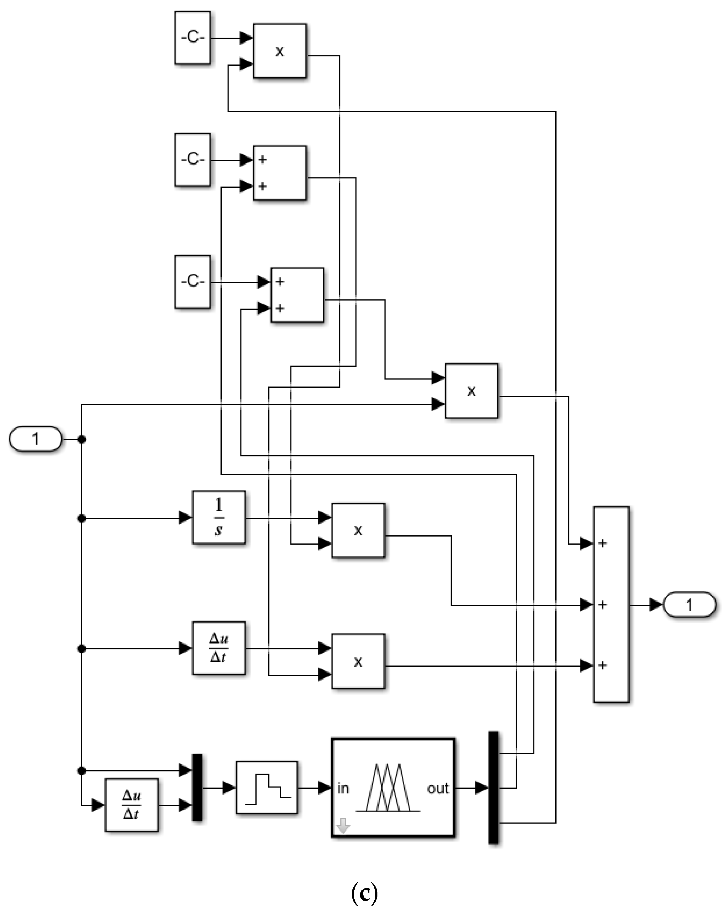
The electro-hydraulic power unit system of a variable pump driven by a servo motor was co-simulated using AMESim2021.2-MATLABR2021B/Simulink software. The hydraulic model was physically modeled in AMEsim and mainly consisted of the electro-hydraulic power source, main control valve, load relief valve, and controller. The control model, on the other hand, was written in Simulink and mainly consisted of fuzzy PID and PID algorithms, both of which were connected to a selection module for comparing the control performance of the fuzzy PID and PID algorithms. Figure 4 shows the system simulation model, where Figure 4a is the AMESim hydraulic system simulation model, Figure 4b is the Simulink control model, and Figure 4c is the fuzzy PID model. The relief valve was used to simulate the system load. The motor speed range was set at 800~1800 r/min, and the pump displacement range was 0~45 cm3/rev. The motor speed was 800 r/min, and the MC-V opening signal at the maximum pump displacement was 3.7. The simulation mainly included the following contents:
(1)
Set the pump pressure step signal and compare the effect of fuzzy PID and PID control on the pump pressure;
(2)
Set the load pressure incremental signal and verify the feasibility of a multi-mode control strategy when the electro-hydraulic power source is in the three different control modes;
(3)
Set the MC-V opening incremental signal and verify the feasibility of the LSSM composite flow control strategy;
(4)
Set the incremental signal of the MC-V pressure difference, verify the feasibility of variable pressure difference control, and analyze its energy-saving effect.

3.1. Comparative Analysis of Fuzzy PID and PID Simulation

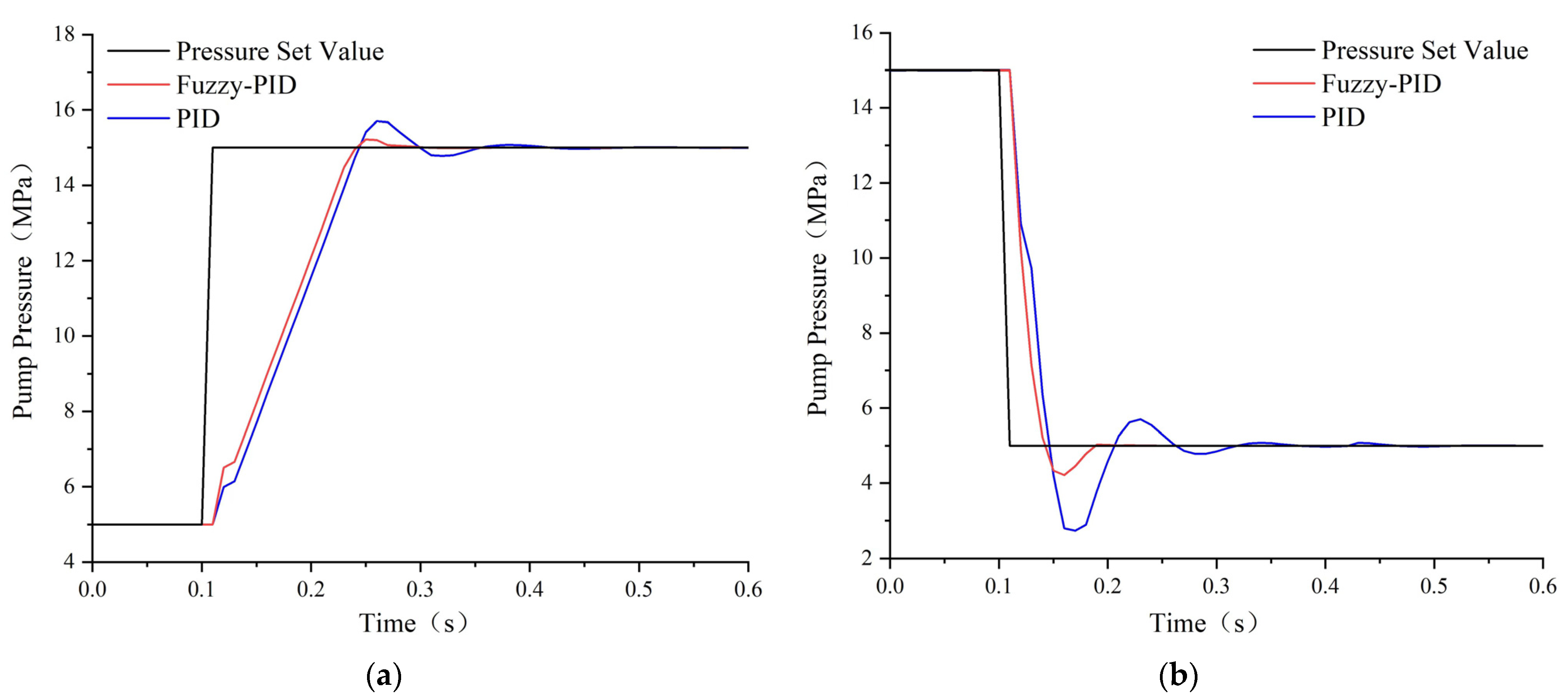
The pump pressure step signal was set, and the pump pressure step response curved under fuzzy PID and PID control are shown in Figure 5. The pressure step-up curve is shown in Figure 5a; the pressure signal was 5 MPa at 0~0.1 s, and the pressure signal stepped up to 15 MPa at 0.1 s. The rise recovery time of fuzzy PID was 0.17 s, and the amount of overshooting was 1.4%. The rise recovery time of PID was 0.26 s, and the amount of overshooting was 4.6%. The pressure step-down curve is shown in Figure 5b; the decline recovery time of fuzzy PID was 0.1 s, and the amount of overshooting was 15.8%. The fall recovery time of PID was 0.21 s, and the overshooting amount was 45.6%. Compared with PID, fuzzy PID had a short response time, low overshooting, and a more stable control effect.

3.2. Flow-Torque-Pressure Composite Control Simulation Analysis

The pressure incremental signal for the load relief valve was set. The MC-V pressure difference signal was set at 2 MPa. The pump pressure control signal was set at 15 MPa, and the torque control signal was set at 50 N·m. Figure 6 shows the curves of pump pressure, load pressure, pump output flow rate, and pump output torque under LSSM composite control. From 0 s to 8.3 s, the electro-hydraulic power source was in flow control mode. As the load pressure increased, the pump pressure and pump output torque also increased. At 8.3 s, the system switched to pressure control mode. The pressure difference was kept at 2 MPa, and the flow rate remained stable at 24.1 L/min. Once the pump output torque reached the set value, the electro-hydraulic power source would switch from flow control mode to torque control mode. As the load pressure increased, the growth rate of pump pressure slowed down, causing the pressure difference to decrease and the flow rate to decrease as well. The torque stabilized at 50 N·m, and the relationship curve between the pump pressure and pump flow rate was a smooth hyperbola. At 14 s, the pump pressure reached the set pressure value, and the electro-hydraulic power source switched from torque control mode back to pressure control mode. As the load pressure increased, the pump pressure stabilized at 15 MPa, and the MC-V pressure difference was reduced to 0. It caused the pump output torque and pump flow rate to decrease to a minimum. The electro-hydraulic power source operated stably in the three control modes and switched smoothly between the three modes.

3.3. Adaptive Displacement-Variable Speed Composite Flow Control Simulation Analysis

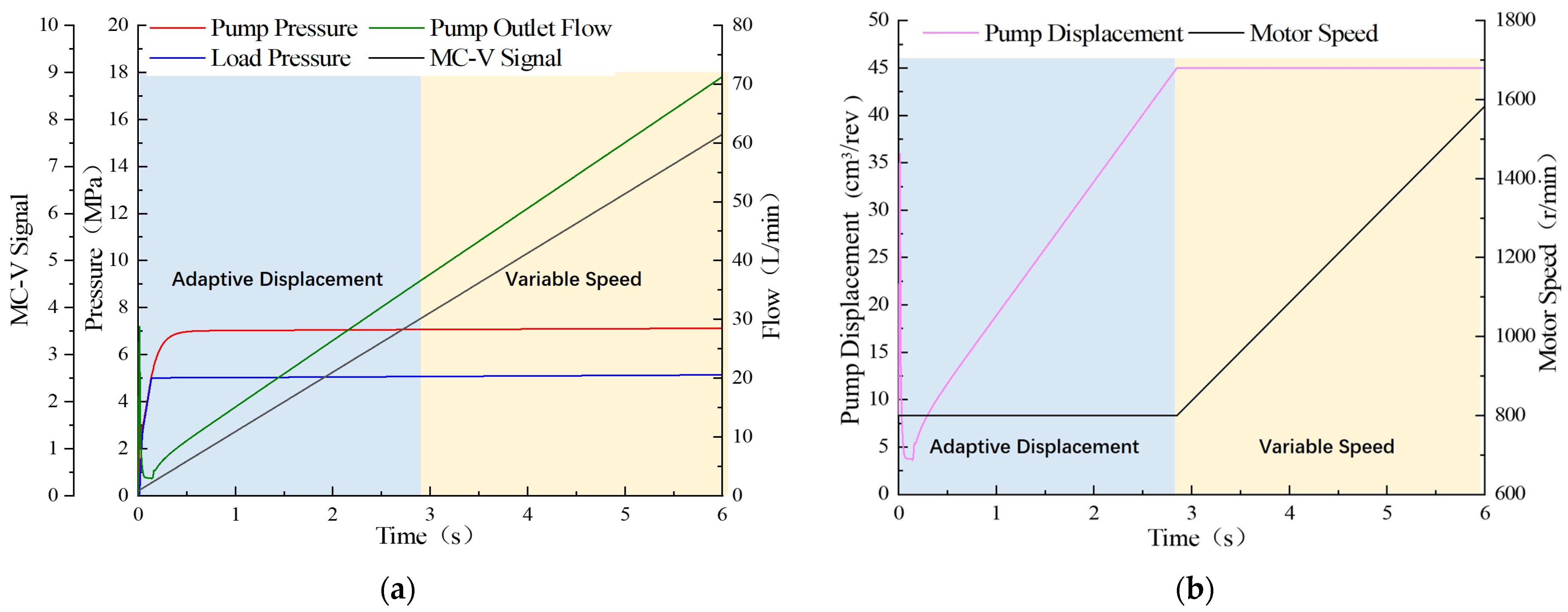
Figure 7 shows the curves of the MC-V opening incremental signal, pump displacement, motor speed, pump pressure, load pressure, and pump flow. From 0 s to 2.8 s, the MC-V control signal is lower than 3.7; the pump outlet flow rate is lower than 36 L/min, the motor runs at 800 r/min, and the pump adapts its displacement to meet the system flow demand. At 2.84 s, the MC-V control signal is 3.7, the outlet flow rate of the pump is 36 L/min, the motor speed is 800 r/min, and the pump operates at maximum displacement. From 2.84 s to 6 s, the control signal is greater than 3.7, the pump operates at maximum displacement. The controller adjusts the motor speed to meet the system flow demand. In flow control mode, the system has a constant pressure difference of the main control valve, a smooth pump flow rate and pump pressure without fluctuations. It indicates that LSSM composite flow control is good.

3.4. Simulation Analysis of Variable Differential Pressure Load Sensitive Control

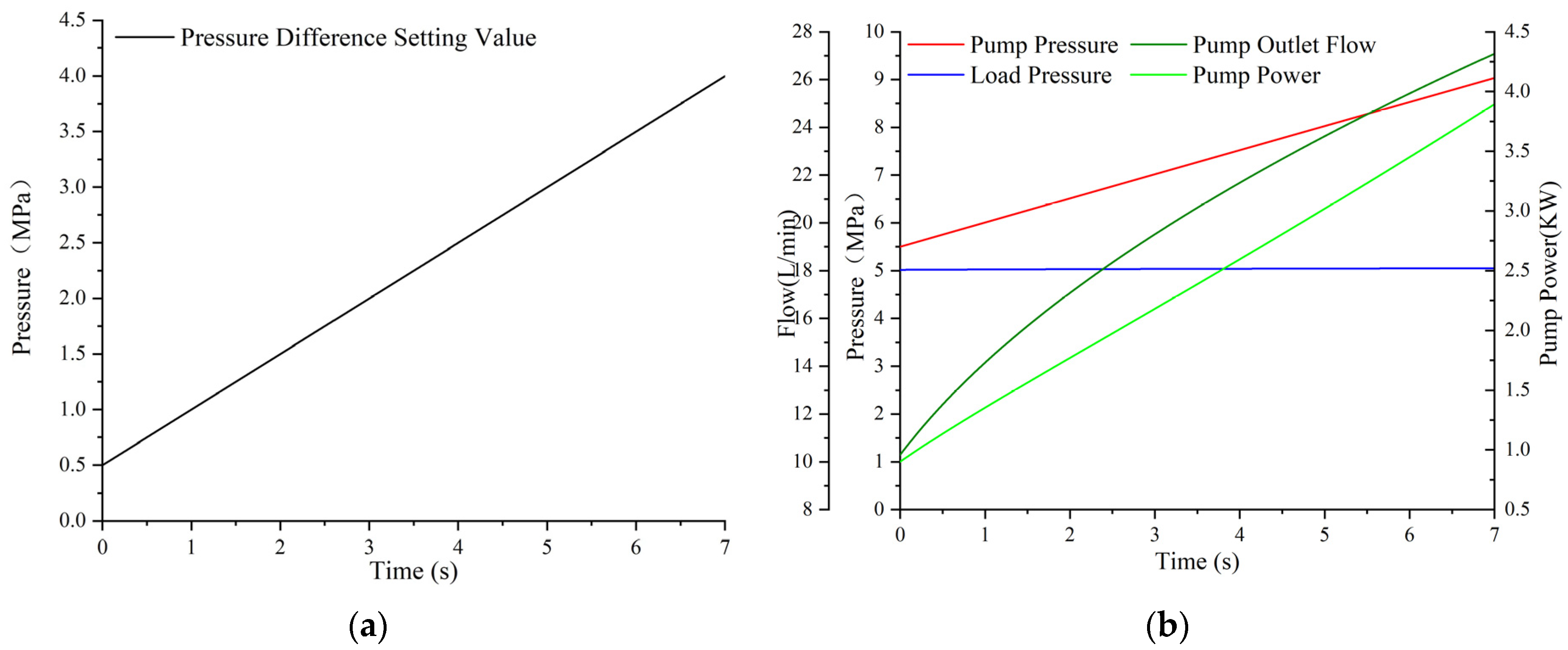
The MC-V pressure difference incremental signal was set. The curves of pump pressure, load pressure, pump output flow rate, and power are shown in Figure 8. From 0 s to 7 s, the load pressure was 5 MPa, the pump pressure increased from 5.5 MPa to 9 MPa, the pressure difference increased from 0.5 MPa to 4 MPa, the pump output flow rate increased from 10.3 L/min to 27.14 L/min, and the pump output power increased from 0.9 KW to 3.9 KW. It is seen that the pump output flow and power rose with the increase in MC-V pressure difference. The energy consumption could be effectively reduced by reducing the set pressure difference according to the system’s actual working conditions.

4. Experimental Studies

4.1. Build a Test Bench

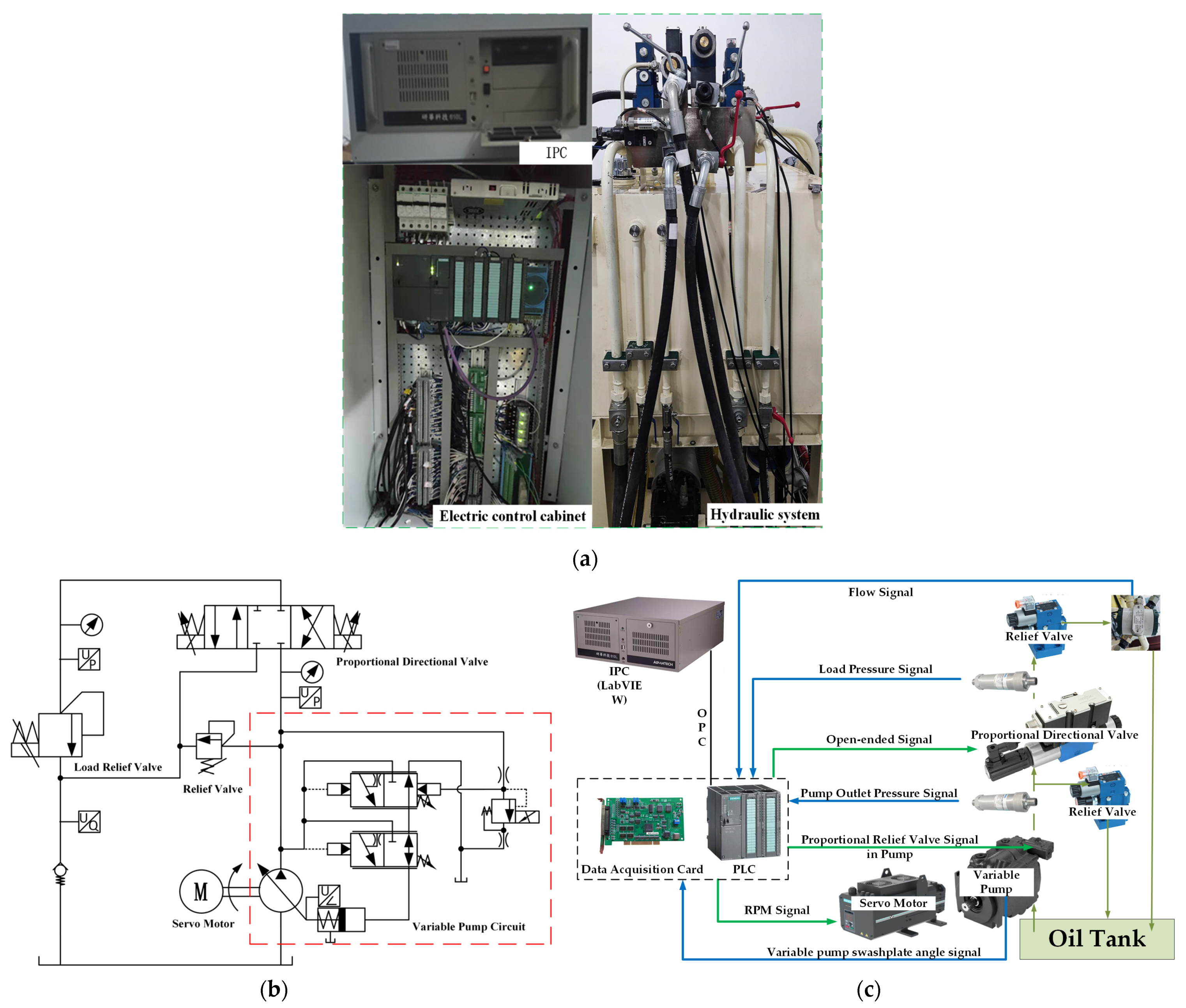
Figure 9 shows the test platform, which is mainly composed of Danish Danfoss S45J series variable pumps, China Weichuang Electric’s EHS100 constant torque servo motors, China Huade Hydraulic’s proportional reversing valves (MC-V) and relief valves, China Advantech’s industrial controllers (IPC) and data acquisition cards, and Germany’s Siemens S7300 PLC. Figure 9a shows the test entity diagram, Figure 9b shows the test hydraulic system schematic diagram, and Figure 9c shows the control program diagram. The upper computer interface and control program are written using LabVIEW2020 software, the PLC can interact with LabVIEW through OPC communication, and the hydraulic system status can be displayed in the LabVIEW upper computer interface. The PLC can be configured to communicate with the servo motor, and the speed of the servo motor can be controlled through communication. Table 2 lists the main parameters of the test platform.

4.2. Pressure Control Analysis

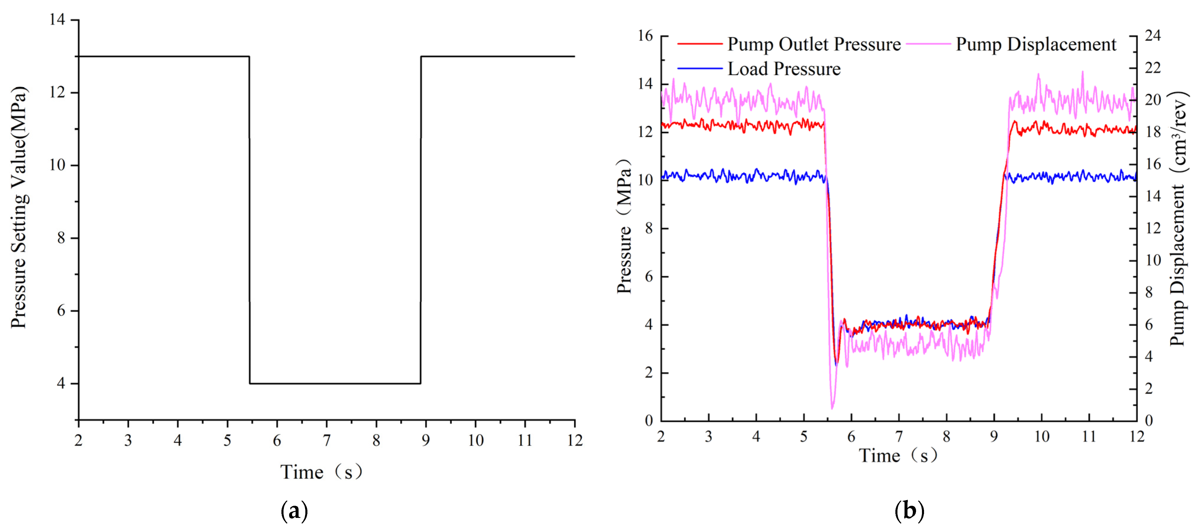
The pump pressure set signal is in Figure 10a, and the pump pressure, load pressure, and pump displacement curves are shown in Figure 10b. From 0 s to 5.5 s, the set value of pump pressure was 13 MPa, the pump pressure was 12.2 MPa, and the load pressure was 10.2 MPa. The pressure difference between the pump pressure and the load pressure was 2 MPa, and the pump displacement was 20 cm3/rev. When the pressure set value dropped to 4 MPa, both the pump pressure and load pressure quickly decreased to 4 MPa within approximately 0.19 s, the pressure difference was 0, and the pump displacement was reduced to the minimum. When the set value of pump pressure rose to 13 MPa at 9 s, the pump pressure recovered to 12.2 MPa, and the load pressure rose to 10.2 MPa within about 0.45 s; moreover, the pressure difference was 2 MPa, and the displacement was 20 cm3/rev. In the pressure control mode, the relative error between the measured pump pressure and the set pressure value was about 0.2%, which indicates excellent control.
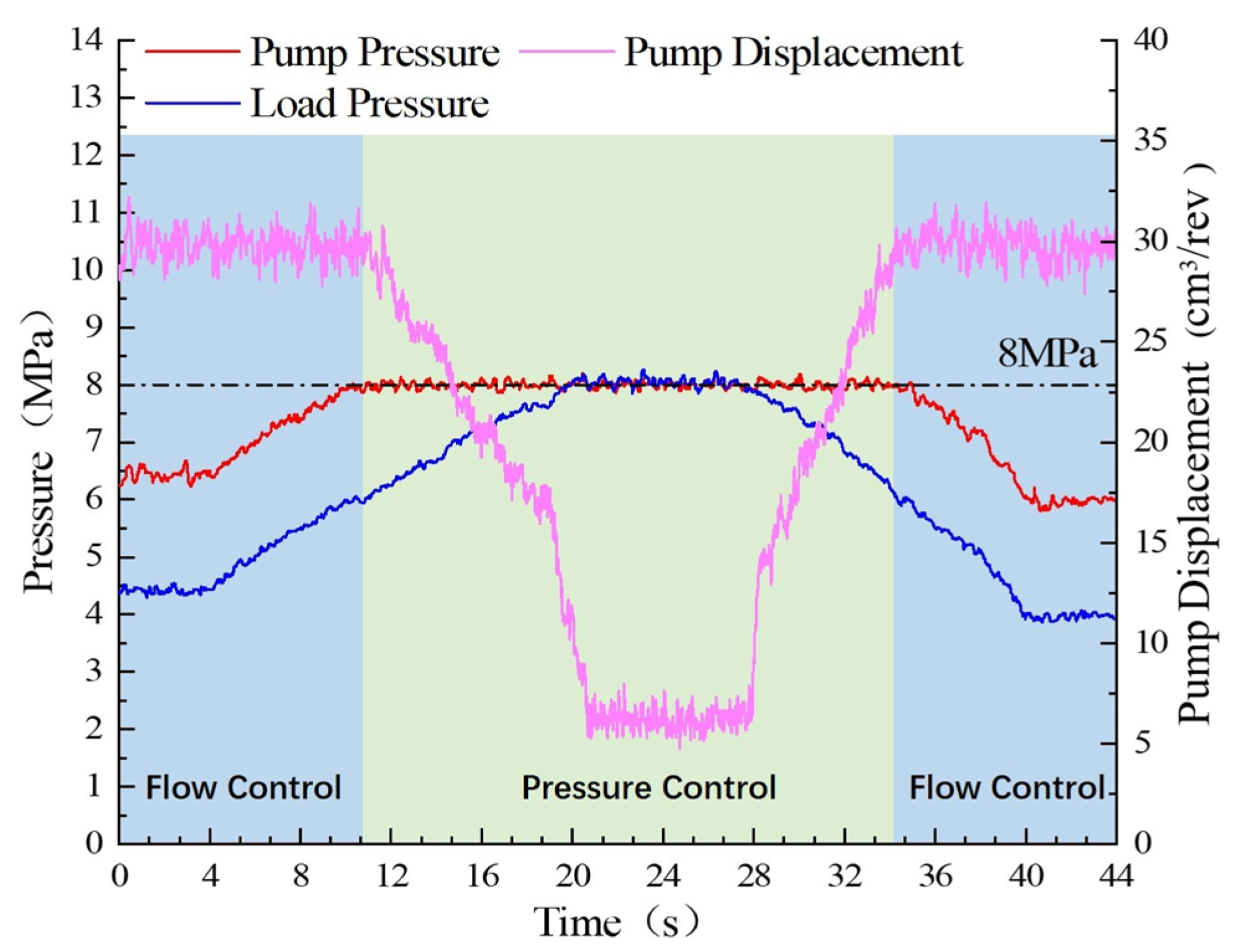
Figure 11 shows the curves of pump pressure, load pressure, and pump displacement in pressure control mode when LR-V is adjusted to increase and decrease the load pressure. LR-V set pressure signal was set to 8 MPa, and the electro-hydraulic power source was in the flow control mode from 0 s to 11 s, with a pressure difference of 2 MPa. The pump pressure increases with the increase in the load pressure. At 11 s, the pump pressure was equal to the set pressure signal. The electro-hydraulic power source switched from flow control mode to pressure control mode. As the load pressure increased, the pump outlet pressure was kept at 8 MPa, and the pressure difference gradually decreased to 0, which caused the pump displacement to reduce to the minimum. At 30 s, the load pressure decreased and made the pressure difference gradually increase. The pump displacement increases as the pressure difference increases. At 34 s, the pressure difference reached 2 MPa, causing the electro-hydraulic power source to switch from the pressure control mode into the flow control mode. As a result, the pump pressure decreased with a decrease in the load pressure. In the pressure control mode, the pump pressure remains constant; the reduction in the pump displacement could minimize overflow loss and improve energy utilization. The electro-hydraulic power source could switch smoothly between the flow control mode and pressure control mode.

4.3. Flow Control Analysis

Figure 12 shows the flow curves of LSSM composite flow control and LSAD regulation for the same step signal of proportional directional valve opening. The flow rate was 7 L/min from 0 s to 4.6 s under LSSM composite flow regulation. The flow rate quickly rose to 81 L/min at 4.6 s within a rise time of about 0.5 s and fell to 7 L/min at 9.5 s within a fall time of about 0.2 s. The overshoot was approximately 42%. The motor speed was 1500 r/min under LSAD flow regulation. The flow rate was 12.5 L/min from 0 s to 3.9 s, then quickly rose to 67.5 L/min in 0.5 s and quickly fell back to 12.5 L/min in 0.2 s, with an overshooting amount of about 66%. By comparing the LSSM composite flow regulation strategy to LSAD regulation, the LSSM flow range increased by about 36% compared with LSAD regulation, and the LSSM overshooting amount was reduced by about 24%. The response time remained consistent between the two regulation strategies. This indicates that the LSSM composite flow regulation strategy has a larger flow range and a more stable control effect.
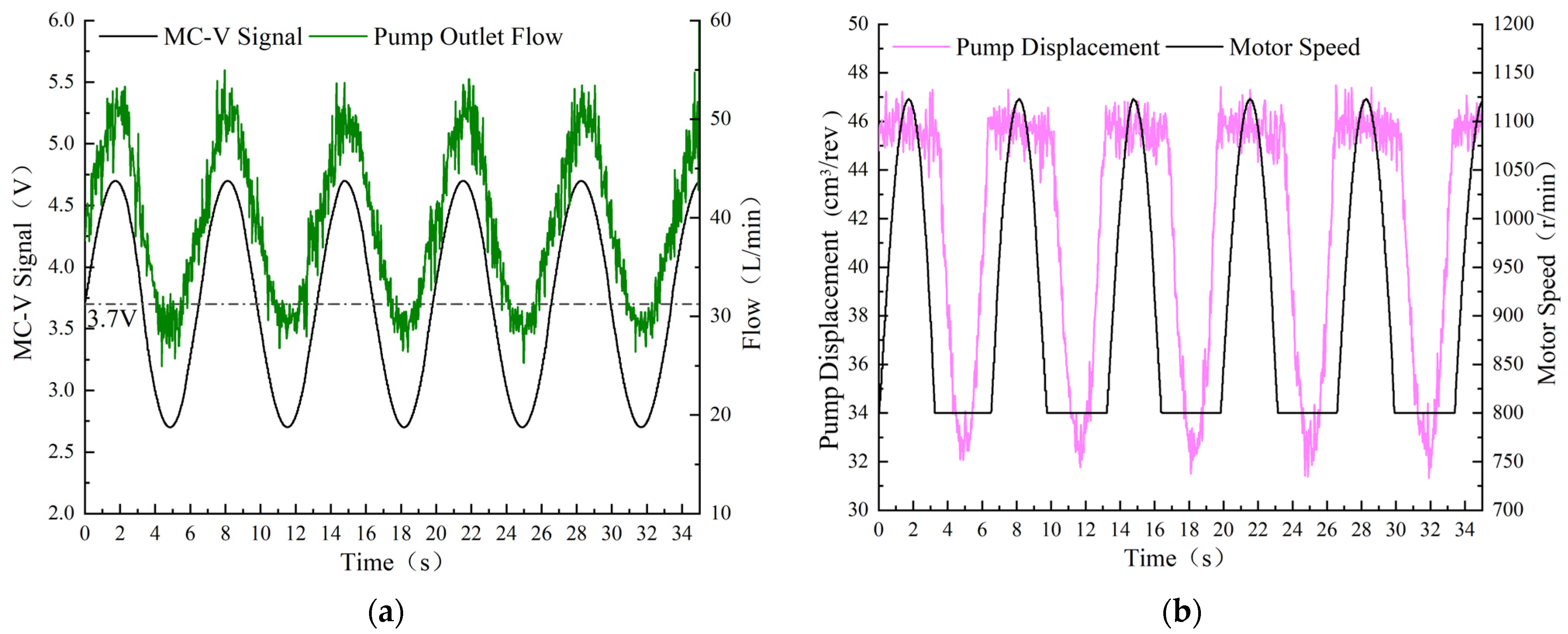
In Figure 13, the MC-V sinusoidal signal is set to an amplitude of 1 V and a frequency of 0.05 Hz. It shows that the average MC-V signal was below 3.7 V, and the pump output flow rate was less than 36 L/min. The motor ran at an idle speed of 800 r/min, and the pump adjusted its displacement adaptively to the output flow rate in a sinusoidal way. When the average MC-V signal was 3.7 V, the pump output flow rate was 36 L/min, the motor speed was 800 r/min, and the pump displacement was 45 cm3/rev. If the MC-V average signal exceeded 3.7 V, the pump output flow rate exceeded 36 L/min at a maximum displacement of 45 cm3/rev. The motor speed was controlled by the controller to match the flow rate demand. The pump output flow rate sinusoidally varied from 28 L/min to 52 L/min and agreed well with the theoretical curve.
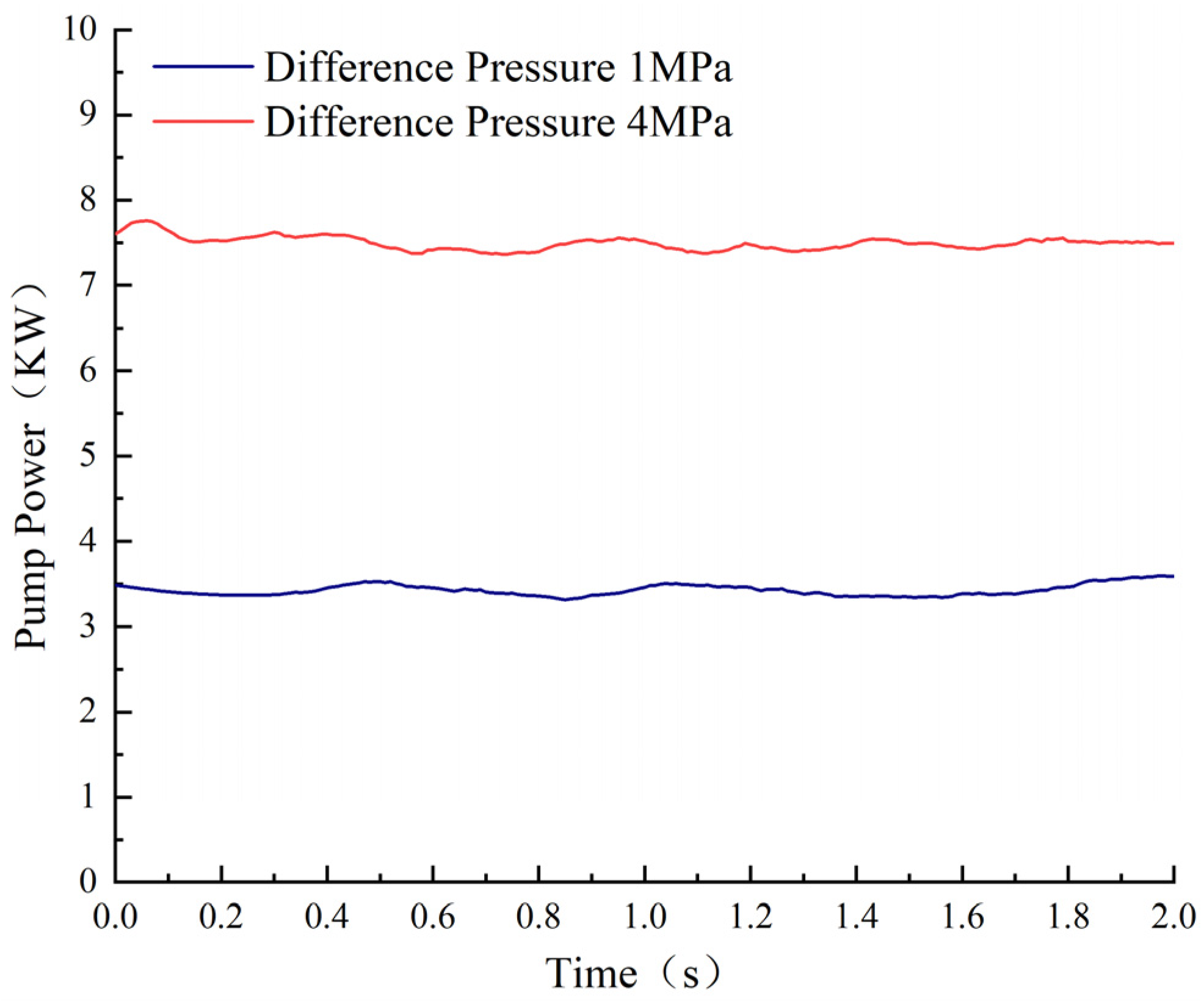
The MC-V set step signal and measured pressure difference are in Figure 14a, and the response curves of pump pressure, load pressure, and pump displacement are shown in Figure 14b. From 0 s to 2.8 s, the pump pressure was 10 MPa, the load pressure was 9 MPa, the pressure difference was 1 MPa, and the pump displacement was 20 cm3/rev. At 2.8 s, the pump pressure rose to 13 MPa while the load pressure remained constant. The pump displacement increased to 33 cm3/rev, the pressure difference rose to 4 MPa, and the rise time was approximately 0.15 s. At 6 s, the pump pressure dropped to 10 MPa, the load pressure remained unchanged, and the pump displacement dropped to 20 cm3/rev. The pressure difference fell to 1 MPa, and the fall time was approximately 0.16 s. In the flow control mode, the relative error between the measurement value and the set value of the MC-V pressure difference was only 0.63%. Figure 15 shows the pump output power curves at various pressure differences. The pump output power was approximately 3.5 KW at a pressure difference of 1 MPa and approximately 7.5 KW at a pressure difference of 4 MPa. The pump output power at the small pressure difference of 1 MPa was reduced by about 46% compared with that at the large pressure difference of 4 MPa. Therefore, a reasonable reduction in pressure difference according to the system’s working conditions could effectively decrease pressure loss and energy consumption.

4.4. Torque Control Analysis

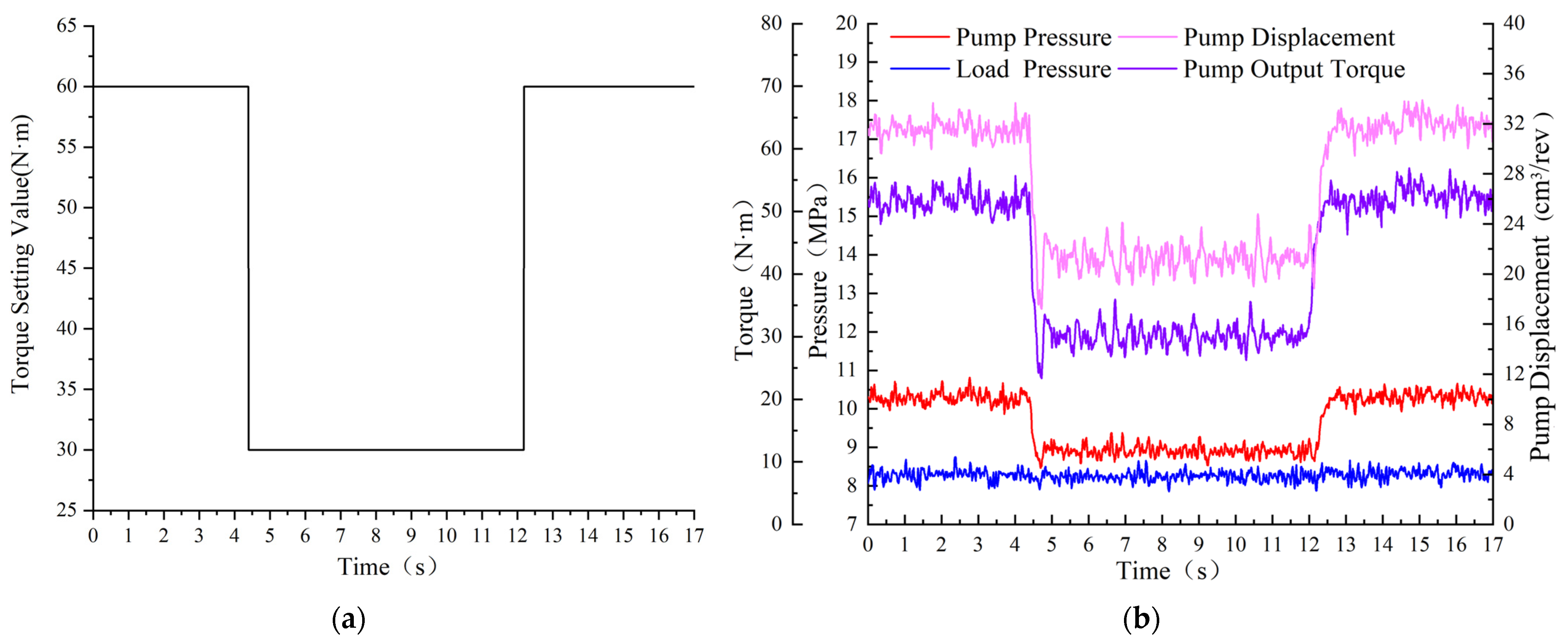
The set step signal of pump torque is in Figure 16a, and the response curves of pump pressure, load pressure, pump displacement, and pump output torque are shown in Figure 16b. From 0 s to 4.4 s, the torque control signal was 60 N·m, the pump pressure was 10.2 MPa, the load pressure was 8.2 MPa, the pressure difference between the pump and the load pressure was 2 MPa, the pump displacement was 32 cm3/rev, and the pump output torque was 52 N·m. At 4.4 s, the torque set signal stepped down to 30 N·m, the pump pressure decreased to 9 MPa, and the load pressure was constant. As the pressure difference decreased, the pump displacement decreased to 21 cm3/rev; the pump output torque decreased to 30 N·m, and the drop time was about 0.2 s. At 12.2 s, the torque control signal stepped up to 60 N·m, the pump pressure rose to 10.2 MPa, and the load pressure was unchanged. With the increase in the pressure difference, the pump displacement rose to 32 cm3/rev, and the pump output torque rose to 52 N·m in about 0.45 s. In the torque control mode, the absolute error between the measured torque value and the torque set value was only 0.16%.
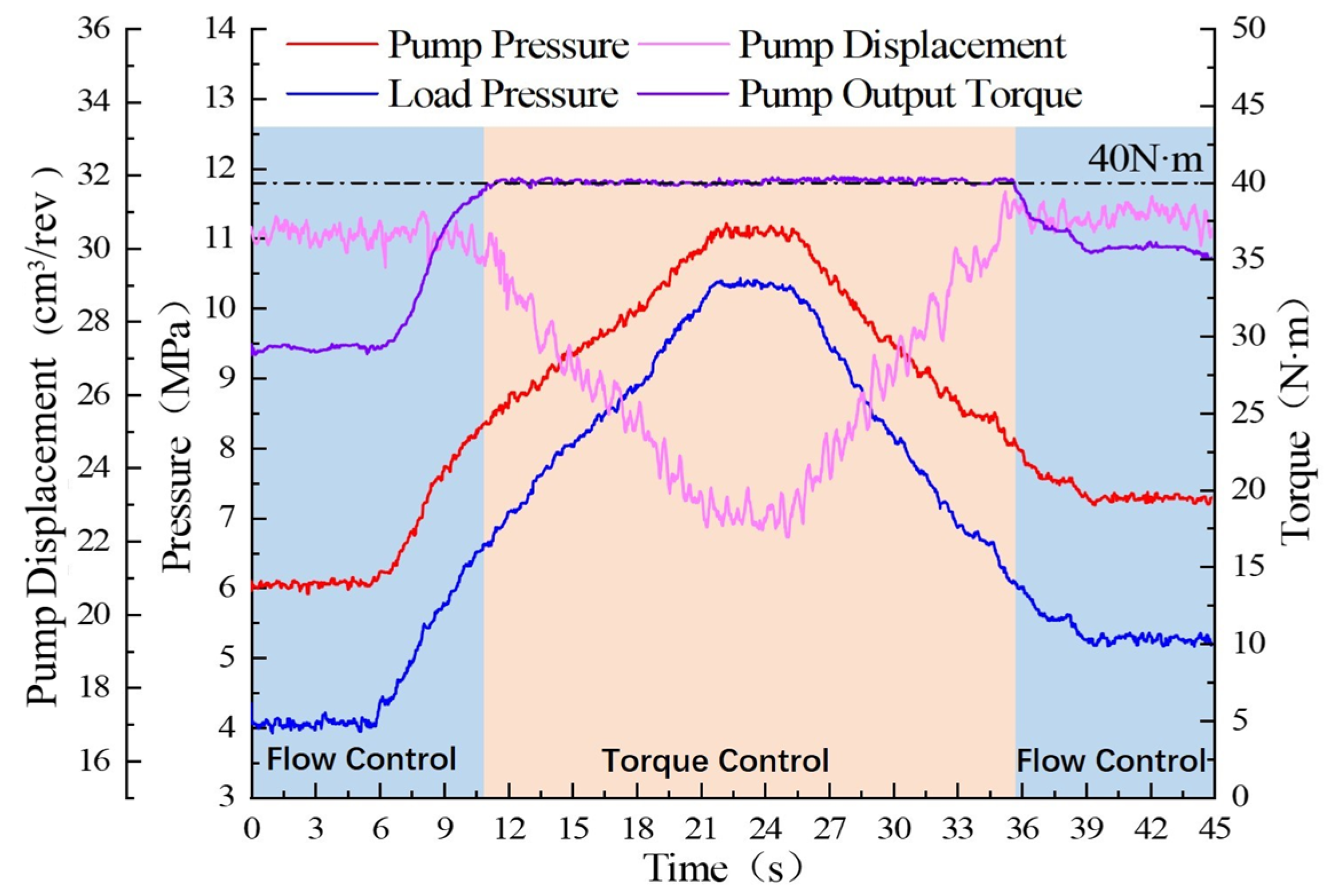
The load relief valve signal was set to increase and decrease the load pressure, and the curves of pump pressure, load pressure, displacement, and pump output torque in torque control mode are shown in Figure 17. The torque limit signal was set to 40 N·m. From 0 s to 10.2 s, the electro-hydraulic power source was in the flow control mode, the pump pressure changed with the load pressure, the pressure difference between them was 2 MPa, and the pump displacement was 27 cm3/rev. The load pressure started to increase at 4.4 s, the pump output torque reached the torque set value at 10.2 s, and the power source switched from the flow control mode to the torque control mode. The pump output torque curve in the torque control mode is shown in Figure 17. With the increase in load pressure, the pressure difference decreased, the pump displacement decreased, and the torque was 40 N·m. At 25.2 s, the load pressure began to decrease, the pressure difference increased, and the pump displacement increased. At 35.8 s, the pump output torque was lower than the set torque value; the power source switched from the torque control mode to the flow control mode, and the pressure difference was kept constant with the decrease in load pressure. This indicates that the power source system switches smoothly between the flow control mode and torque control mode without obvious fluctuation.

5. Summary

The multi-mode control strategy and switch rules were proposed, including pressure, flow, and torque control modes, and the LSSM composite flow regulation strategy was developed. The fuzzy PID controller was designed based on pump outlet pressure control, and the AMESim/Simulink co-simulation of the electro-hydraulic power source system was conducted. The experimental platform was built, and experimental research was conducted. The main conclusions are the following:
(1)
Fuzzy PID control has a faster response time, more stable control, and better tracking effect on pump outlet pressure compared with PID controllers;
(2)
The pump could switch well between pressure, flow, and torque modes according to the load pressure change, and the multi-mode switches are smooth;
(3)
The precision of pressure and torque control is relatively high, with control errors of 0.2% and 0.16%, respectively;
(4)
Compared with load-sensitive adaptive displacement regulation, the LSSM composite flow regulation strategy has a larger flow range and a more stable control effect. The pump output flow could automatically choose variable speed fixed displacement regulation or variable displacement fixed speed regulation based on the estimated flow rate. The output flow rate and power of the pump increase with the increase in the pressure difference of the main control valve. Reducing the pressure difference according to the actual working conditions could effectively reduce energy consumption.

Author Contributions

Conceptualization, Z.Z., Y.Y., and Z.L.; methodology, Z.Z., Y.Y., and L.L.; software, Y.Y. and Q.C.; validation, Z.Z., Y.Y., Q.C., K.J., and Z.L.; writing—original draft preparation, Y.Y.; writing—review and editing, Y.Y. and Z.Z.; supervision, Y.Y. and Z.Z.; data curation, Y.Y. All authors have read and agreed to the published version of the manuscript.

Funding

This research has been supported by the National Natural Science Foundation of China (52175057), the Natural Science Foundation of Shanxi Province (20210302123215), the special fund for Science and Technology Innovation Teams of Shanxi Province (202304051001033).

Data Availability Statement

The data are available upon request from the corresponding author.

Conflicts of Interest

The authors declare no conflicts of interest.

References

  1. Liu, H.; Zhang, X.; Quan, L.; Zhang, H. Research on energy consumption of injection molding machine driven by five different types of electro-hydraulic power units. J. Clean. Prod. 2020, 242, 118355. [Google Scholar] [CrossRef]
  2. Yan, Z.; Ge, L.; Quan, L. Energy-Efficient Electro-Hydraulic Power Source Driven by Variable-Speed Motor. Energies 2022, 15, 4804. [Google Scholar] [CrossRef]
  3. Lovrec, D.; Kastrevc, M.; Ulaga, S. Electro-hydraulic load sensing with a speed-controlled hydraulic supply system on forming-machines. Int. J. Adv. Manuf. Technol. 2009, 41, 1066–1075. [Google Scholar] [CrossRef]
  4. Huang, H.; Jin, R.; Li, L.; Liu, Z. Improving the Energy Efficiency of a Hydraulic Press Via Variable-Speed Variable-Displacement Pump Unit. ASME J. Dyn. Sys. Meas. Control 2018, 140, 111006. [Google Scholar] [CrossRef]
  5. Tong, Z.; Wu, S.; Tong, S.; Yue, Y. Energy-saving technologies for construction machinery: A review of electro-hydraulic pump-valve coordinated system. J. Zhejiang Univ. Sci. A 2020, 21, 331–349. [Google Scholar] [CrossRef]
  6. Ge, L.; Quan, L.; Zhang, X.; Zhao, B.; Yang, J. Efficiency improvement and evaluation of electric hydraulic excavator with speed and displacement variable pump. Energy Convers. Manag. 2017, 150, 62–71. [Google Scholar] [CrossRef]
  7. Yan, Z. Characteristics of high energy-efficient Electro-hydraulic power source driven by servo motor and variable pump. Proc. Inst. Mech. Eng. Part C J. Mech. Eng. Sci. 2023, 237, 1525–1536. [Google Scholar] [CrossRef]
  8. Liu, B.; Yan, Z.; Ge, L.; Quan, L. Electric Drive Hydraulic Power Source Characteristics of Small Hydraulic Excavator. Trans. Chin. Soc. Agric. Mach. 2019, 50, 387–393. [Google Scholar]
  9. Sun, Z.; Zeng, Q.; Wan, L.; Xiao, Y. Dynamic Response Analysis of the Bi-Tandem Axial Piston Pump with Dual-Loop Positive Flow Control under Pressure Disturbance. Actuators 2023, 12, 260. [Google Scholar] [CrossRef]
  10. Liao, W.; Chen, S.; Chen, C. Research of negative flow control characteristics for axial piston pump based on hydraulic and mechanical co-simulation. In Proceedings of the 2012 3rd International Conference on System Science, Engineering Design and Manufacturing Informatization, Chengdu, China, 20–21 October 2012; pp. 79–83. [Google Scholar]
  11. Tian, X.; Stump, P.; Vacca, A.; Fiorati, S.; Pintore, F. Power-Saving Solutions for Pre-Compensated Load-Sensing Systems on Mobile Machines. Trans. ASABE 2021, 64, 1435–1448. [Google Scholar] [CrossRef]
  12. Nurmi, J.; Mattila, J. Global Energy-Optimal Redundancy Resolution of Hydraulic Manipulators: Experimental Results for a Forestry Manipulator. Energies 2017, 10, 647. [Google Scholar] [CrossRef]
  13. Pan, Y.; Li, Y.; Liang, D. The influence of dynamic swash plate vibration on outlet flow ripple in constant power variable-displacement piston pump. Proc. Inst. Mech. Eng. Part C J. Mech. Eng. Sci. 2019, 233, 4914–4933. [Google Scholar] [CrossRef]
  14. Hu, Q.; Zhang, H.; Tian, S.; Qin, X. Performances analysis of a novel load-sensing hydraulic system with overriding differential pressure control. Proc. Inst. Mech. Eng. Part C J. Mech. Eng. Sci. 2017, 231, 4331–4343. [Google Scholar]
  15. Salomaa, V.; Minav, T.; Mattila, J.; Pietola, M. Efficiency Study of an Electro-Hydraulic Excavator. Fluid Power Networks: Proceedings: 19th–21th March 2018: International Fluid Power Conference; RWTH Aachen University: Aachen, Germany, 2018; pp. 372–385. [Google Scholar]
  16. Chu, M.; Kang, Y.; Chen, Y.; Chang, Y. The Swashplate Angle Control of a Variable Displacement Pump with an Electro-Hydraulic Proportional Valve. Mater. Sci. Forum 2008, 594, 389–400. [Google Scholar] [CrossRef]
  17. Wei, C.; Wang, X.; Chen, Y.; Wu, H.; Chen, Y. Adaptive Fuzzy Power Management Strategy for Extended-Range Electric Logistics Vehicles Based on Driving Pattern Recognition. Actuators 2023, 12, 410. [Google Scholar] [CrossRef]
  18. Won, D.; Kim, W.; Tomizuka, M. High Gain Observer Based Integral Sliding Mode Control for Position Tracking of Electro-hydraulic Servo Systems. IEEE/ASME Trans. Mechatron. 2017, 22, 2695–2704. [Google Scholar] [CrossRef]
  19. Liao, Y.; Zhao, W.; Feng, J.; Lian, Z. Optimization of the Control Performance of a Novel 3/2 Water Proportional Directional Valve with a Special Position Following Servo Mechanism. IEEE/ASME Trans. Mechatron. 2024, 1–10. [Google Scholar] [CrossRef]
  20. Vilanova, R.; Alfaro, V.M. Robust PID Control: An Overview. Rev. Iberoam. De Autom. E Inform. Ind. 2011, 8, 141–158. [Google Scholar] [CrossRef]
  21. Somefun, O.A.; Akingbade, K.; Dahunsi, F. The dilemma of PID tuning. Annu. Rev. Control 2021, 52, 65–74. [Google Scholar]
  22. Kuantama, E.; Vesselenyi, T.; Dzitac, S.; Tarca, R. PID and Fuzzy-PID Control Model for Quadcopter Attitude with Disturbance Parameter. Int. J. Comput. Commun. Control 2017, 12, 519–532. [Google Scholar] [CrossRef]
  23. Esfandyari, M.; Fanaei, M.A.; Zohreie, H. Adaptive fuzzy tuning of PID controllers. Neural Comput. Appl. 2013, 23, S19–S28. [Google Scholar] [CrossRef]
  24. Anis, Y.H.; Kassem, S.A. Performance of constant power operated swash plate axial piston pumps with fuzzy logic controllers. In Proceedings of the ASME 2013 International Mechanical Engineering Congress and Exposition, San Diego, CA, USA, 15–21 November 2013; pp. 15–21. [Google Scholar]
  25. Cheng, M.; Zhang, J.; Xu, B.; Ding, R.; Yang, G. Anti-windup scheme of the electronic load sensing pump via switched flow/power control. Mechatronics 2019, 61, 1–11. [Google Scholar] [CrossRef]
  26. Lingenfelter, K.R.; Bruns, A.; Daley, C. Electronic Load Sense Control with Electronic Variable Load Sense Relief, Variable Working Margin, and Electronic Torque Limiting. U.S. Patent 9759212B2, 12 September 2017. [Google Scholar]
  27. Lin, T.; Lin, Y.; Ren, H.; Chen, H.; Li, Z.; Chen, Q. A double variable control load sensing system for electric hydraulic excavator. Energy 2021, 223, 119999. [Google Scholar] [CrossRef]
  28. Kim, J.H.; Jeon, C.S.; Hong, Y.S. Constant pressure control of a swash plate type axial piston pump by varying both volumetric displacement and shaft speed. Int. J. Precis. Eng. Manuf. 2015, 16, 2395–2401. [Google Scholar] [CrossRef]
  29. Wang, W.; Wang, B. An Energy-Saving Control Strategy with Load Sensing for Electro-Hydraulic Servo Systems. Stroj. Vestn. J. Mech. Eng. 2016, 62, 709–716. [Google Scholar] [CrossRef]
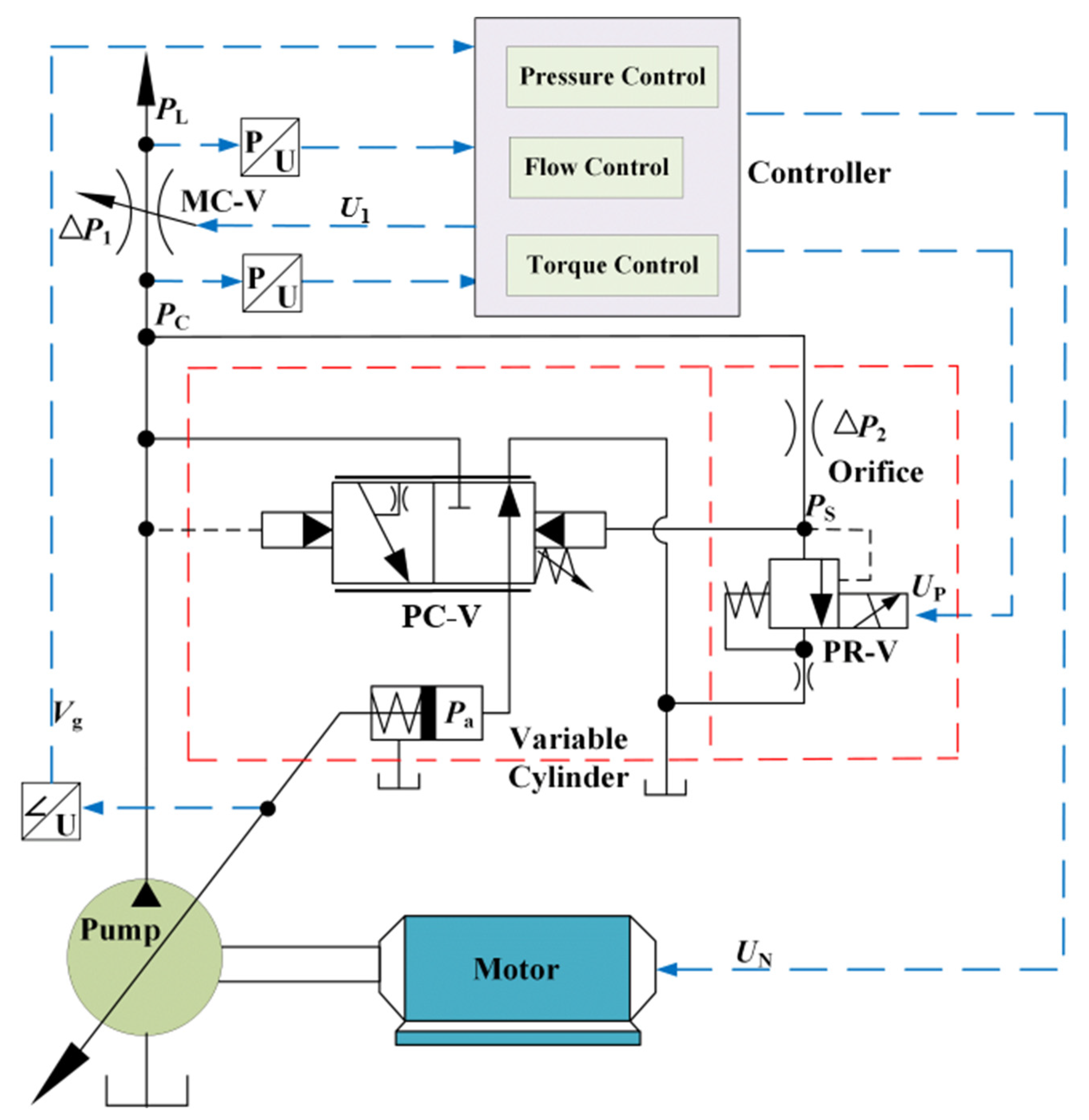
Figure 1. Control schematic diagram of variable pump system driven by servo motor.
Actuators 13 00190 g001
Figure 2. Fuzzy PID controller principle.
Actuators 13 00190 g002
Figure 3. Multi-mode control flowchart.
Actuators 13 00190 g003
Figure 4. System simulation model. (a) Physical model; (b) Control model; (c) Fuzzy PID model.
Actuators 13 00190 g004aActuators 13 00190 g004b
Figure 5. Pressure step response curve. (a) Pressure step rise; (b) Pressure step down.
Actuators 13 00190 g005
Figure 6. Composite control curve. (a) Load pressure setting; (b) Pump pressure, load pressure, pump torque and pump outlet flow curves; (c) Pump pressure vs. outlet flow rate characteristic curve.
Actuators 13 00190 g006
Figure 7. Composite flow control simulation curve. (a) Main control valve signal, pump output flow, pump pressure and load pressure curves; (b) Motor speed vs. pump displacement curve.
Actuators 13 00190 g007
Figure 8. Simulation curve of load sensing control with variable difference. (a) Pressure difference setting; (b) pump pressure, pump outlet flow, load pressure, and pump power curves.
Actuators 13 00190 g008
Figure 9. Test platforms. (a) Test physical drawing; (b) Test hydraulic system schematic diagram; (c) Control program diagram.
Actuators 13 00190 g009
Figure 10. Step pressure control. (a) Pressure control signal; (b) Pump pressure, load pressure, and pump displacement curves.
Actuators 13 00190 g010
Figure 11. Pressure control test curve.
Actuators 13 00190 g011
Figure 12. Flow step response curve.
Actuators 13 00190 g012
Figure 13. Composite flow regulation characteristic curve with sinusoidal signal from MC-V. (a) MC-V valve control signal and pump output flow curve; (b) pump displacement vs. motor speed curve.
Actuators 13 00190 g013
Figure 14. Pressure difference control response curve for step signal. (a) Pressure difference measured value vs. pressure difference setting value curve; (b) Pump pressure, load pressure, and pump displacement curves.
Actuators 13 00190 g014
Figure 15. Pump power curves for different pressure differences.
Actuators 13 00190 g015
Figure 16. Step torque control characteristic curve. (a) Torque control step signal; (b) Pump pressure, load pressure, pump displacement, and pump output torque curves.
Actuators 13 00190 g016
Figure 17. Test curves in torque control mode.
Actuators 13 00190 g017
Table 1. Fuzzy rule table.
K p / K i / K d er
NBNMNSZOPSPMPB
eNBNB/NB/PSNB/NM/PSNM/NM/ZOZO/ZO/ZOPM/PM/NSPB/PM/NSZO/ZO/PB
NMPB/NB/NSPB/NB/NSPM/NM/NSPM/NM/NSPS/NS/NSZO/ZO/ZOZO/ZO/NS
NSPM/NM/NBPM/NM/NBPS/NS/NMPS/NS/NSZO/ZO/NSNS/PS/ZONM/PS/PS
ZOPS/NM/NBPS/NS/NMZO/NS/NMZO/ZO/NSZO/PS/ZOPS/PS/ZOPS/PM/PS
PSPM/NS/NBPM/NS/NMZO/ZO/NSZO/PS/NSZO/PS/PSPS/PM/ZOPS/PM/PS
PMPM/ZO/NMPM/ZO/NSPM/ZO/NSPS/PM/NSPS/PM/PSPM/PB/ZOPM/PB/PS
PBPB/ZO/PSPB/ZO/ZOPM/PS/ZOPM/PM/ZOPM/PB/PSPB/PB/ZOPB/PB/PM
Table 2. Main parameters of the test platform.
ParametersValue
Maximum displacement of hydraulic pump (cm3/rev)45
Maximum limiting pressure of the hydraulic pump (MPa)26
Pressure limiting valve set pressure (MPa)30
Rated speed of servo motor (r/min)1800
Servo motor setting speed range (r/min)800–1800
Rated torque of servo motor (N·m)105
Main control valve opening signal when motor 800 r/min, pump 45 cm3/rev (V)3.7
Disclaimer/Publisher’s Note: The statements, opinions and data contained in all publications are solely those of the individual author(s) and contributor(s) and not of MDPI and/or the editor(s). MDPI and/or the editor(s) disclaim responsibility for any injury to people or property resulting from any ideas, methods, instructions or products referred to in the content.