Abstract
This paper analyzes the viability of different solutions to passively augment the axial stiffness of a horizontal axis radial levitation passive magnetic bearing (PMB) with a previously studied topology. The zero-field cooling (ZFC) of high-temperature superconductor (HTS) bulks promotes higher magnetic impulsion and levitation forces and lower electromagnetic losses than those with field-cooling (FC) but, on the other hand, the guiding stability is much lower than those with FC. Because of stability reasons, FC was adopted in most superconducting maglev systems. The trend of this research group has been to develop a horizontal axis HTS ZFC radial levitation PMB presenting notable levitation forces with reduced electromagnetic losses, defined by a topology that creates guiding stability. Previous work has shown that optimizing the bearing geometry to maximize magnetic guidance forces might not be enough to guarantee the axial stiffness required for many applications. First, the extent to which guidance forces are augmented by increasing the number of HTS bulks in the stator is evaluated. Then, the axial stiffness augmentation by passively adding two limiting permanent magnet (PM) rings is evaluated. The results show that the axial stiffness is highly augmented by adding limiting PM rings with no significant additional investment. This change enables the use of the studied ZFC superconducting PMB in high-precision axial stability applications, such as precision gyroscopes, horizontal axis propellers, and turbines.
1. Introduction
High-temperature superconducting (HTS) levitation bearings present some important advantages for applications where high speeds are achieved or where frictionless technologies are required. Some examples of these applications are high-speed flywheels [1], energy storage for space applications [2], high-speed motors and generators [3], and high-speed textile applications [4].
Most of the proposed solutions of HTS levitation bearings present a field-cooled (FC) HTS, due to guidance stability [5]. However, with FC, the electromagnetic losses are higher and there is an increased risk of mechanical damage (cracking), due to the significant magnetic field penetration in the HTS materials. Adopting zero-field cooling (ZFC) instead of FC allows for higher impulsion and levitation forces and an increase in the gap and safety distance [6,7]. Also, ZFC reduces the magnetic field penetration and electromagnetics losses in HTS bulks, increasing efficiency [8,9] and extending their lifetime [10,11]. However, due to their repulsive behavior, ZFC topologies require an enhancement of axial stiffness to compete with FC topologies. In reference [12], a study was carried out to compare the axial stiffness of levitation bearings in FC and ZFC modes, showing a higher stiffness for the FC topology, up to four times that of the ZFC one.
Some methodologies for increasing the stiffness of levitation systems have been proposed for passive magnetic levitation and bearing devices. In reference [13], the authors propose the use of permanent magnets and magnetic plates to increase the stiffness of an axial flux HTS motor for aircraft propulsion. Axial airgap distances and torque dynamics are given in reference [14], concerning another axial flux HTS motor for aircraft propulsion.
In reference [15], the authors propose the optimization of the geometry of a ring-shaped permanent magnet (PM) passive vibration isolator to maximize the axial magnetic force and stiffness. The PM’s width, height, and air gap width were critical for balancing stiffness and levitation. In reference [16], a new method to measure the stiffness of a repulsive passive bearing in a single gimbal magnetically suspended control moment gyroscope was proposed and validated experimentally. In reference [17], the magnetic forces and axial stiffness were analyzed for a new axial-type superconducting magnetic bearing (SMB) based on the interaction behavior between a PM and two closed superconducting coils. Lateral stabilization was achieved by placing HTS coils at each side of the magnetic bearing.
The importance of the stiffness of magnetic systems is not only related to magnetic levitation systems. For example, in reference [18], a model was developed to determine the magnetic stiffness in radial flux permanent magnet generators of direct-drive wind turbines from the structural mechanical stiffness, depending on the verified operation deflection. Also, the impact of stiffness is key in developing electromagnetic negative-stiffness springs [19]. Thus, the techniques developed for these systems can also be analyzed to increase the stiffness of horizontal axis HTS ZFC levitation bearings.
Following the advancements made in methodologies to increase the stiffness of levitation systems, in this paper, we propose to evaluate ways to passively augment the axial stiffness of a studied horizontal axis HTS ZFC radial levitation passive magnetic bearing (PMB). We propose the enhancement of axial stiffness by passively adding limiting PM rings aligned with the PM rotor and independent from the PM rotor at a specific distance from the side rotor PM rings. With this new insignificant cost addition, the modified HTS ZFC magnetic levitation bearing may compete in terms of guiding stability with HTS FC magnetic levitation bearings for high-precision axial stability applications such as precision gyroscopes, high-speed horizontal axis propellers, and turbines.
This research will contribute to solving the problem associated with the limited application of HTS ZFC levitating bearings, due to their inherent reduced lateral stability. The deployment of HTS ZFC bearings has the advantages of ensuring the increase in levitation forces and the levitation gap safety distance, as well as reducing the electromagnetic penetration and losses in HTS materials, increasing their lifetime. On the other hand, the process of ZFC has the disadvantage of requiring more initial work and energy to transfer the cooled HTS from the cooling position to the levitating position, compared to the FC process.
Section 2 presents the designs and materials for the existing and modified bearing geometries and describes the adopted analysis methods to reduce numerical processing. Section 3 presents the result of the determination and validation of the equivalent magnetic permeability when the rotor and stator axes are aligned. Also, it evaluates the axial stiffness augmentation by adding HTS bulks in the stator or limiting PM rings aligned with the rotor. The results are discussed in Section 4 and the main conclusions are stated in Section 5.
2. Materials and Methods
This section presents and describes the designs, materials, and analysis methods considered in this study.
2.1. Designs and Materials of the Studied HTS ZFC Passive Bearing Experimental Prototype
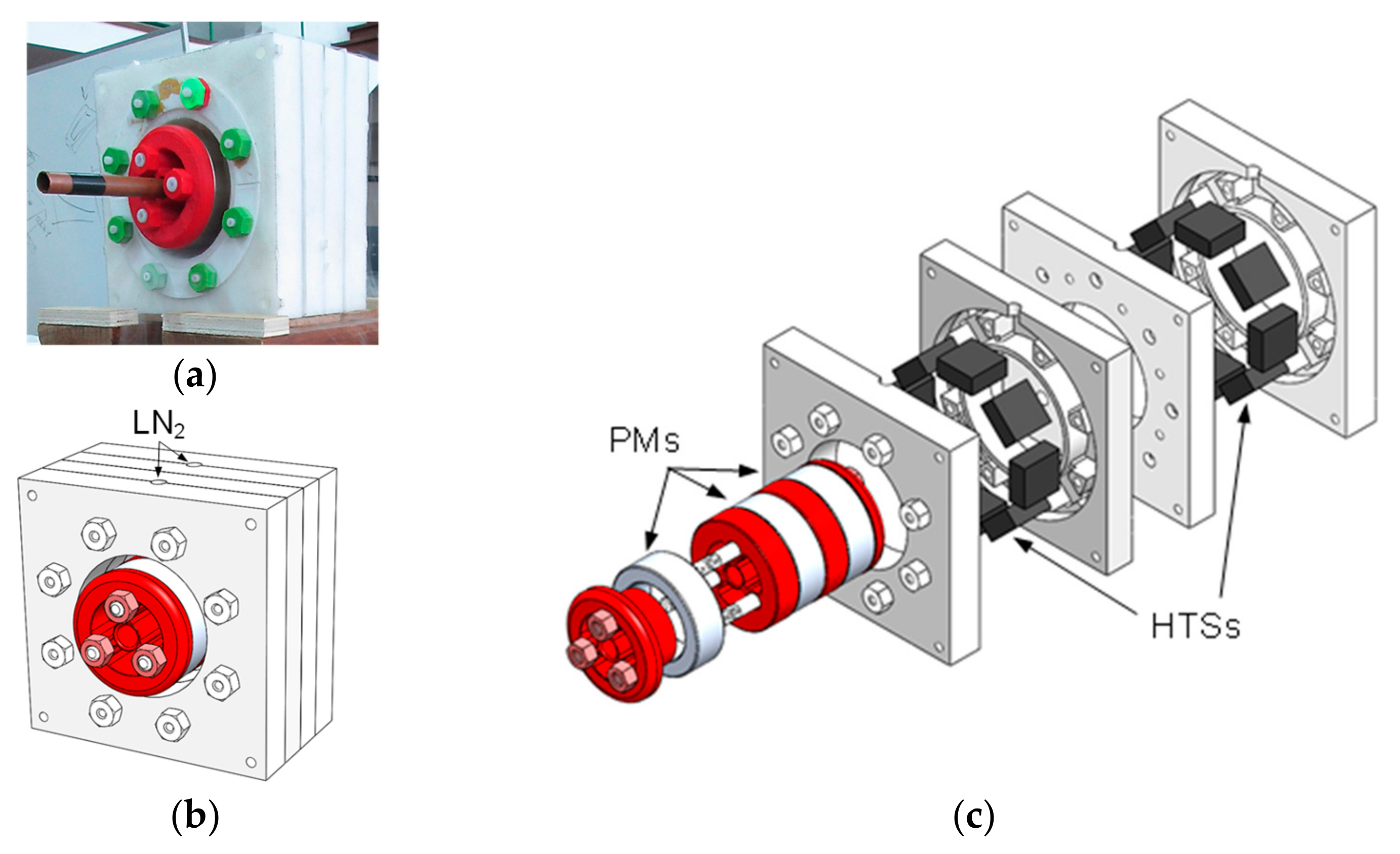
In this paper, we propose to analyze different techniques to improve the axial stiffness of the horizontal axis high-temperature superconducting (HTS) zero-field cooled (ZFC) horizontal axis radial levitation bearing shown in Figure 1. Figure 1a,b show a photo and the 3D design of the studied HTS ZFC bearing experimental prototype assembly. Figure 1c shows the 3D design of the experimental prototype extrusion.
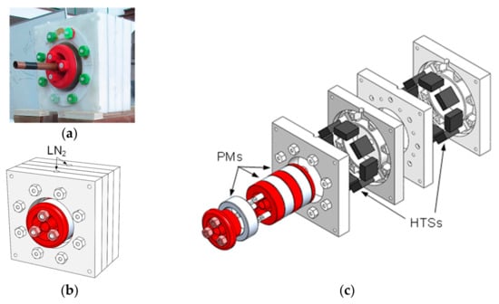
Figure 1.
A photo (a), the assembly 3D design (b), and the extruded 3D design (c) of the studied HTS ZFC passive magnetic bearing experimental prototype.
The studied passive bearing geometry comprises a PM rotor including three radially magnetized PM rings in an alternate polarization arrangement. The polarization of the intermediate PM ring is the opposite of the polarizations of the two side PM rings, resulting in an attraction between adjacent PM rings in the rotor [20]. PM rings of Neodymium Iron Borum (NdFeB) with grade N40 were used in tests and were considered in finite element analysis (FEA) simulations. The rotor’s structure to support the PM rings was built with Polylactic Acid Plastic (PLA) that was printed using a 3D Computer-Aided Design (CAD) printer.
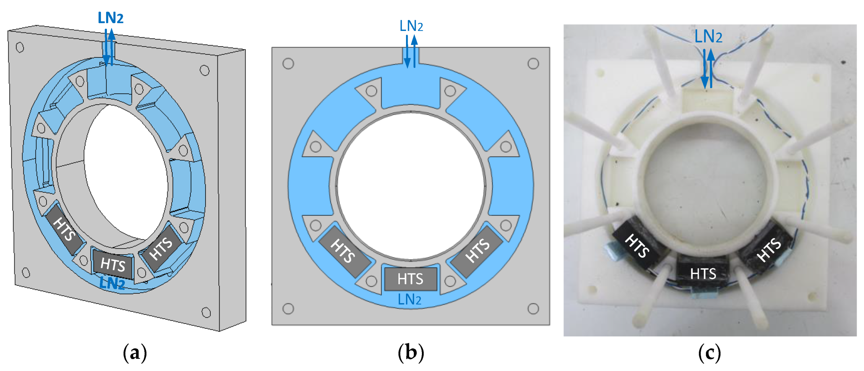
Also, a stator housing two discontinuous rings of HTS bulks was cryocooled using ZFC, each ring with a maximum of eight HTS bulks [20]. HTS bulks of Yttrium Barium Copper Oxide (YBCO) were used in tests and were considered in FEA simulations. The stator was made of rigid high-density polyurethane (PUR) because of its low thermal conductivity and easily machinable material. The stator was manufactured using a Computer Numerical Control (CNC) milling tool. The cryostat included two chambers for two discontinuous rings of HTS bulks, each formed by two symmetric half-parts. On the top of each chamber, a hole opens to the environment for liquid nitrogen (LN2) replenishment. Figure 2a–c show, respectively, the 3D perspective, 2D projection, and a photo of one stator chamber half-part, housing only three HTS bulks at its bottom. The LN2 circulation zone is highlighted in blue, where direct contact exists between YBCO bulks and LN2 in the tested concept-proving experimental prototype.
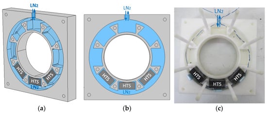
Figure 2.
The 3D perspective (a), 2D projection (b), and photo (c) of one stator chamber half-part, housing only three HTS bulks at its bottom.
The basic concept of the considered HTS permanent magnet arrangement consisted of cryocooling the HTS bulks in the stator in the zero-field condition, far from the influence of the rotor magnetic fields, with the rotor away from its operating position. After the cooling of the HTS bulks down to the average LN2 temperature, the rotor is positioned in its operation position in the stator cavity. During the approximation of the rotor to its operation position, currents are induced in the HTS bulks due to variations in the applied magnetic fields. The induced currents generate according to Ampere’s law the initial magnetization of the HTS bulks. Repulsive magnetic forces appear due to the interaction between the HTS bulks’ magnetization field and the applied magnetic field from the rotor PM rings. Low guidance is provided by the studied HTS ZFC passive bearing geometry because each discontinuous ring of HTS bulks is located in between adjacent PM rings with opposite polarization.
To facilitate the process of ZFC, after cryocooling the HTS bulks far from the rotor to not be under the influence of its magnetic fields, the rotor was always placed in the stator cavity, with the rotor and stator axes aligned. With this procedure, the initial induced current distribution and magnetization of the HTS bulks distributed around the stator would be almost the same, independent of their azimuthal position.
The initial prediction of magnetic levitation and guidance forces and the measurement of rotor dynamics were performed in reference [20]. Studies on the LN2 consumption and YBCO bulk temperature evolution for different thermal processes in the initial ZFC and the operation of the experimental bearing prototype were presented in reference [21]. A methodology was developed to predict the released thermal power evolution from the measured LN2 mass loss rate, to determine the autonomous safety service time of the studied horizontal HTS ZFC levitating bearing [22].
2.2. Geometry Modifications to Augment the Axial Stiffness of the HTS ZFC Passive Bearing
Optimization of the PM ring and HTS bulk ring spacings was carried out to maximize the bearing guiding stability, considering both bulks of dimensions and [23]. The results have shown that the magnetic guidance is slightly higher with the first bulk size and the magnetic levitation is higher with the second bulk size. For this reason, and because of the availability of good condition bulks of dimensions in our laboratory, the latter bulk size is considered in this analysis.
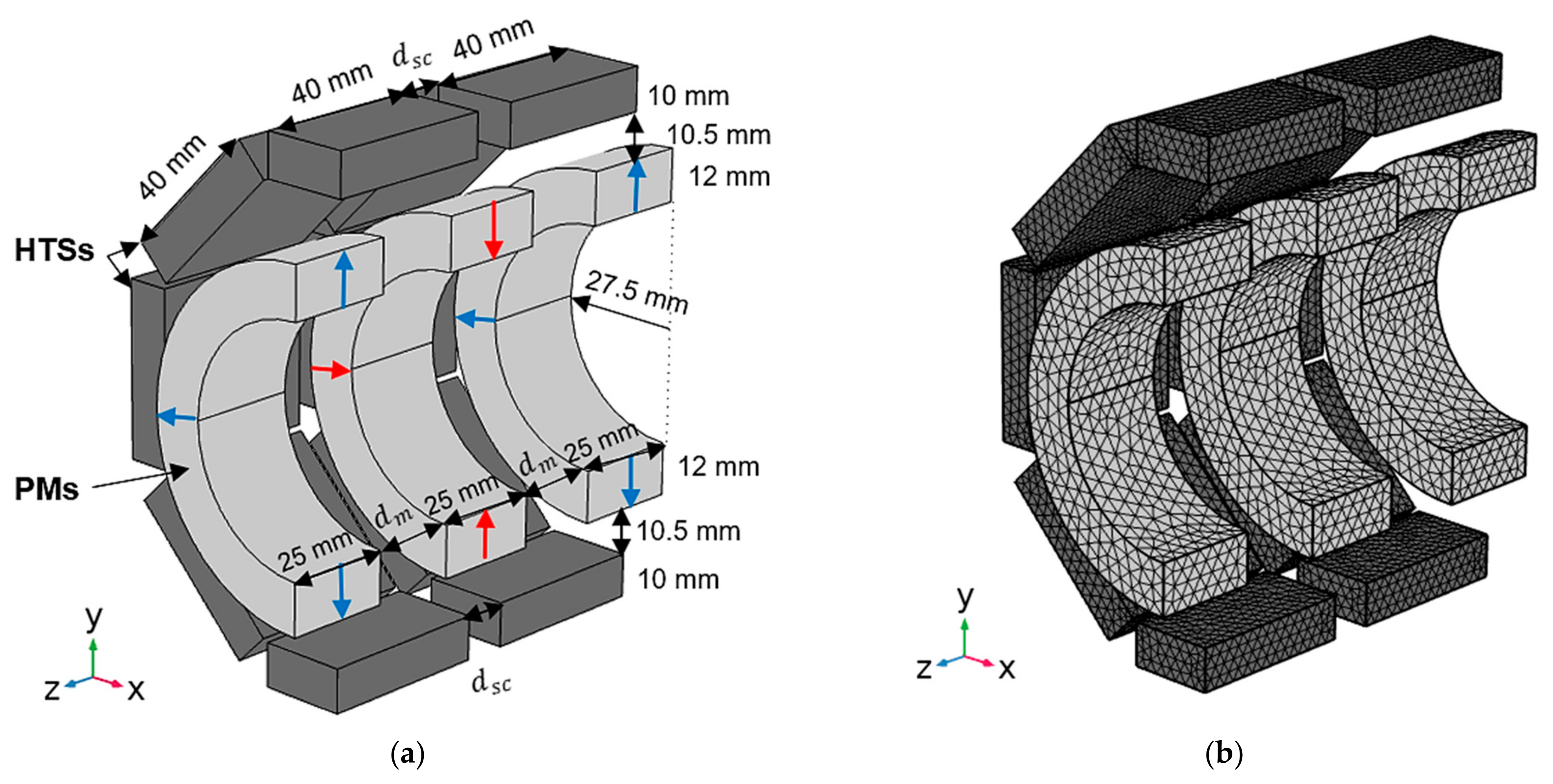
Figure 3a,b show the dimensioned longitudinal bisection design of the studied bearing topology and corresponding mesh grid for 3D FEA. Variables and refer to the distances, respectively, between the two discontinuous rings of HTS bulks in the stator and between adjacent PM rings in the rotor.
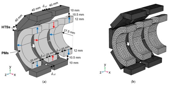
Figure 3.
Dimensioned design of a longitudinal bisection of the studied bearing (a) and mesh grid considered for 3D FEA (b).
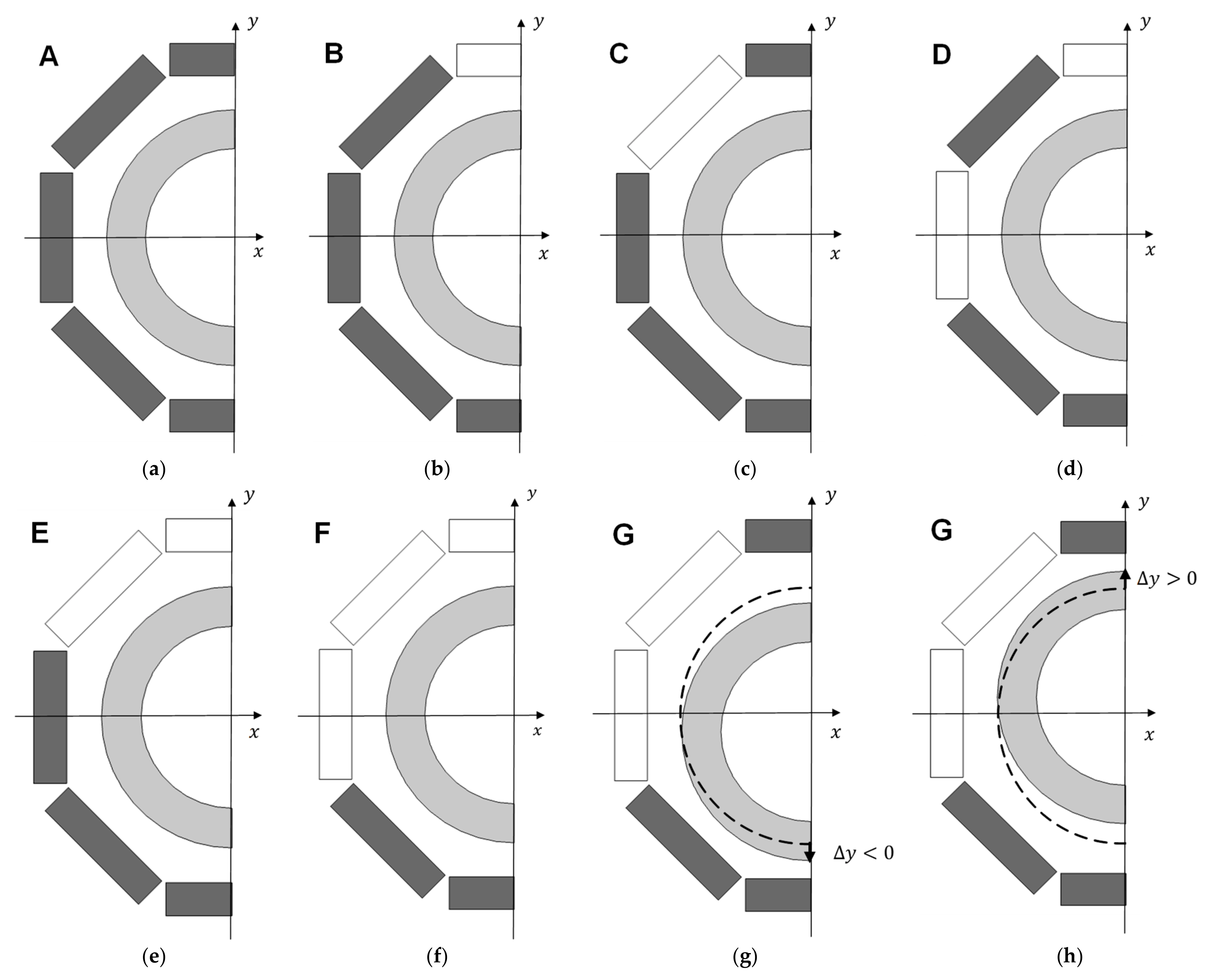
Figure 4a–h show the different possible topologies of the asymmetric distribution of HTS bulks in the stator that were considered in this study. By completing the stator with a total of sixteen HTS bulks, referred to as Topology A in Figure 4a, it would be impossible to levitate with the rotor axis at the center position. With this topology of HTS bulks, distributed symmetrically in the stator, the resulting magnetic levitation force in the y-direction would be zero and gravity pulls the rotor down, forcing it to levitate with eccentricity. For the exposed reasons, similar levitation asymmetry would be verified if continuous HTS rings were used in the stator. From performed commercial inquiries, the cost of one complete continuous HTS ring is about of a complete discontinuous ring with eight HTS bulks, according to Topology A.
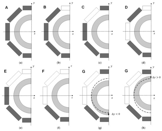
Figure 4.
Lateral bisection views of six topologies with asymmetric distribution of HTS bulks in the stator: topology A (a), topology B (b), topology C (c), topology D (d), topology E (e), topology F (f), topology G with (g), and topology G with (h).
Figure 4g,h show a negative vertical deviation () and a positive vertical deviation () of the rotor for Topology G, respectively. The dashed lines refer to the rotor position at , with the rotor and stator axes aligned.
Topology F in Figure 4f, with only six HTS bulks at the stator bottom, maximizes the resulting magnetic force in the y-direction, referred to as levitation force, with less investment in HTS bulks. Because this topology enables a wider range of vertical deviations, , where levitation is verified, it was considered in previous studies for validation by the experimental testing of magnetic forces predicted using numerical FEA. On the other hand, the verified magnetic guidance forces are minimal with Topology F, because the higher the magnetic energy portion used for levitation, the lower the magnetic energy portion used for guidance.
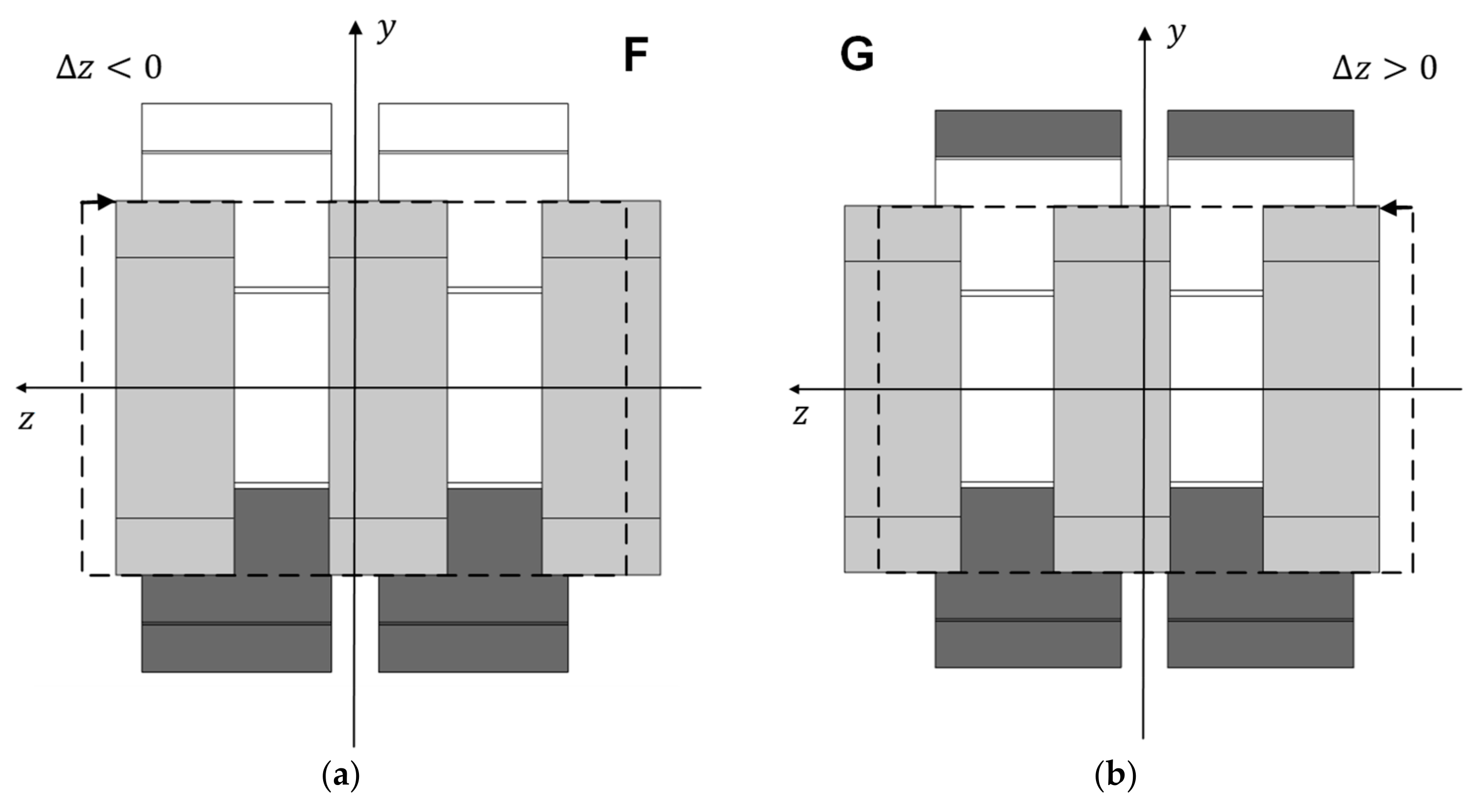
Figure 5a,b show views of longitudinal bisections, respectively, for Topology F with a negative axial deviation of the rotor () and for Topology G with a positive axial deviation of the rotor (). The dashed lines refer to the rotor position at .
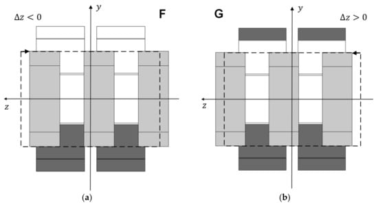
Figure 5.
Longitudinal bisection views, respectively, for Topology F with in (a) and for Topology G with in (b).
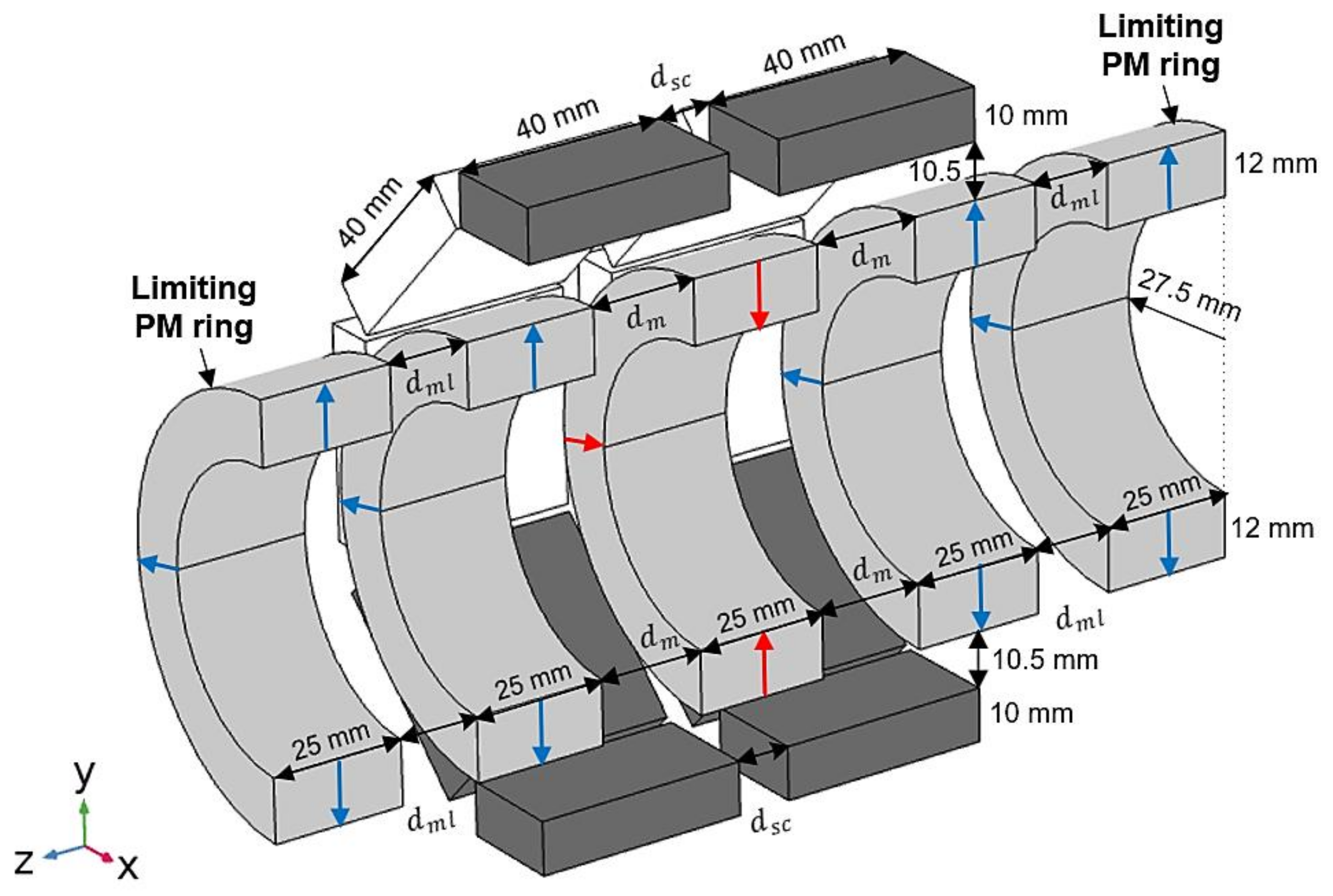
Figure 6 shows the design of the proposed change by adding two limiting radially magnetized PM rings with the same polarization as the rotor edge PM rings, to augment the axial stiffness with no significant additional investment. Variable represents the distance between the rotor edge PM rings and the limiting PM rings, with no axial deviation of the rotor ().
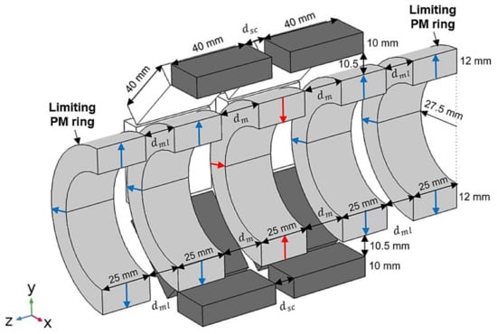
Figure 6.
Design of the proposed change, adding two limiting radially magnetized PM rings with the same polarization as the rotor edge PM rings, to increase axial stiffness significantly.
2.3. Adopted Method to Reduce Numerical Processing in the Prediction of Magnetic Guidance Forces
The required numerical processing in the 3D FEA prediction of magnetic forces could be significantly reduced if a simplified model of equivalent permeability is considered for HTS bulks [24]. This approach avoids performing a complete electromagnetic analysis using non-linear conductivity power laws and the Kim–Anderson model for type II superconductors [25,26] to determine the detailed current distributions and magnetization of HTS bulks.
Previous results [23] have shown that for the considered ZFC radial bearing, the equivalent permeability of HTS bulks varies with the rotor vertical deviation. Their equivalent permeability does not notably vary on the limited range of possible rotor axial deviations when kept with no radial deviation. Once the prediction and validation of magnetic guidance forces are performed, keeping the rotor and stator axes coincident (with no radial deviation of the rotor), the FEA numerical prediction of magnetic guidance forces is determined, assuming the approximate value of equivalent magnetic permeability for the HTS bulks verified when there is no rotor radial deviation. Results related to the determination and validation of such equivalent magnetic permeability values are presented in Section 3.1.
3. Results
This section first presents the results of the determination and validation of the HTS bulks’ equivalent magnetic permeability with no rotor radial deviation. Then, results on the axial stiffness depending on the considered topology and number of HTS bulks in the stator are presented. In the end, results are presented from the determination and validation of the axial stiffness augmentation by adding limiting PM rings with the same polarization as the rotor edge PM rings.
3.1. Equivalent Magnetic Permeability for HTS Bulks with No Radial Deviation of the PM Rotor
The HTS bulks’ equivalent permeability was validated, with no radial deviation of the PM rotor, considering Topology F, because this topology maximizes the range of rotor vertical deviations where levitation is verified. Also, with this topology, the number of HTS bulks is only six, minimizing the required amount of numerical processing. The six HTS bulks are located on the lower half of the stator, being enough to determine and validate the variation of the HTS bulks’ magnetic permeability with the rotor vertical deviation, considering that the bearing geometry presents symmetry with relation to the horizontal plane of longitudinal bisection.
Figure 7a shows the distribution of magnetic field density resultant from 3D FEA simulations with no radial deviation of the PM rotor, considering HTS bulks with equivalent magnetic permeability . Figure 7b shows the distributions of and the detailed current density obtained, considering the complete electromagnetic non-linear power-law model for the conductivity of type II superconductors with . The obtained distribution of nearby HTS bulk boundaries is similar using the two models.
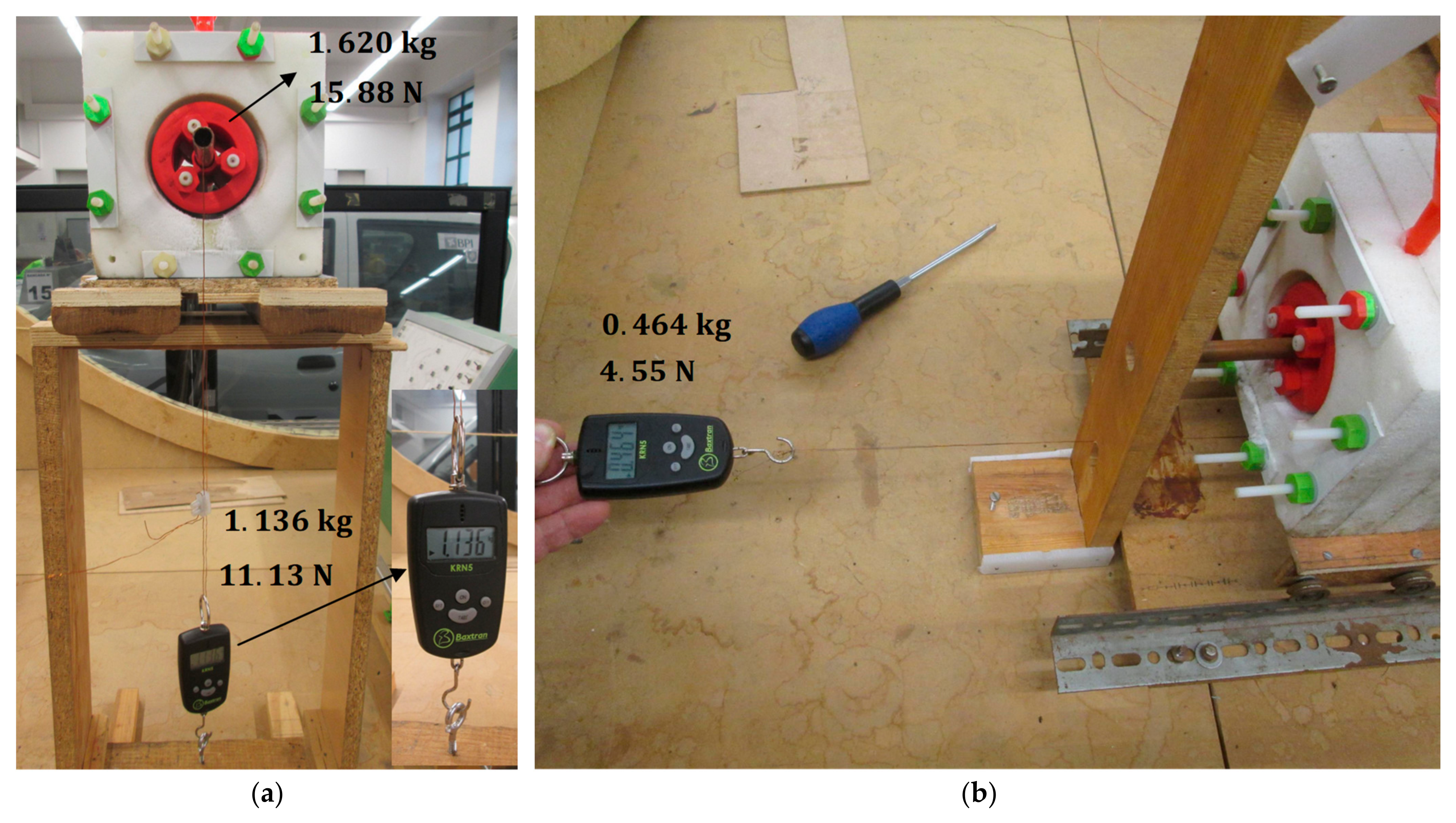
Figure 8a shows the experimental measurement of the magnetic levitation force with no vertical deviation ) and no axial deviation ) of rotor D20 ). The measured levitation force magnitude, , is the sum of the rotor gravity, , with the impulsion force measured with Baxtran KRN05 dynamometer, Figure 8b shows the experimental measurement of the magnetic guidance force, , with no vertical deviation ) and an axial deviation, , of rotor D20, where the predicted guidance force is maximum. The measured guidance force with and was
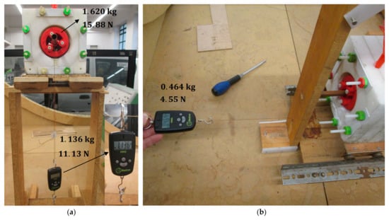
Figure 8.
Experimental measurement of with Topology F and rotor D20 at and (a), and of with Topology F and rotor D20 at and (b).
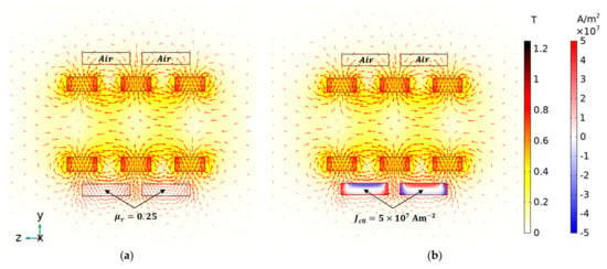
Figure 7.
Distributions obtained using 3D FEA simulations for , considering HTS bulks with (a), as well as for and considering the complete EM model with (b).
Figure 7.
Distributions obtained using 3D FEA simulations for , considering HTS bulks with (a), as well as for and considering the complete EM model with (b).
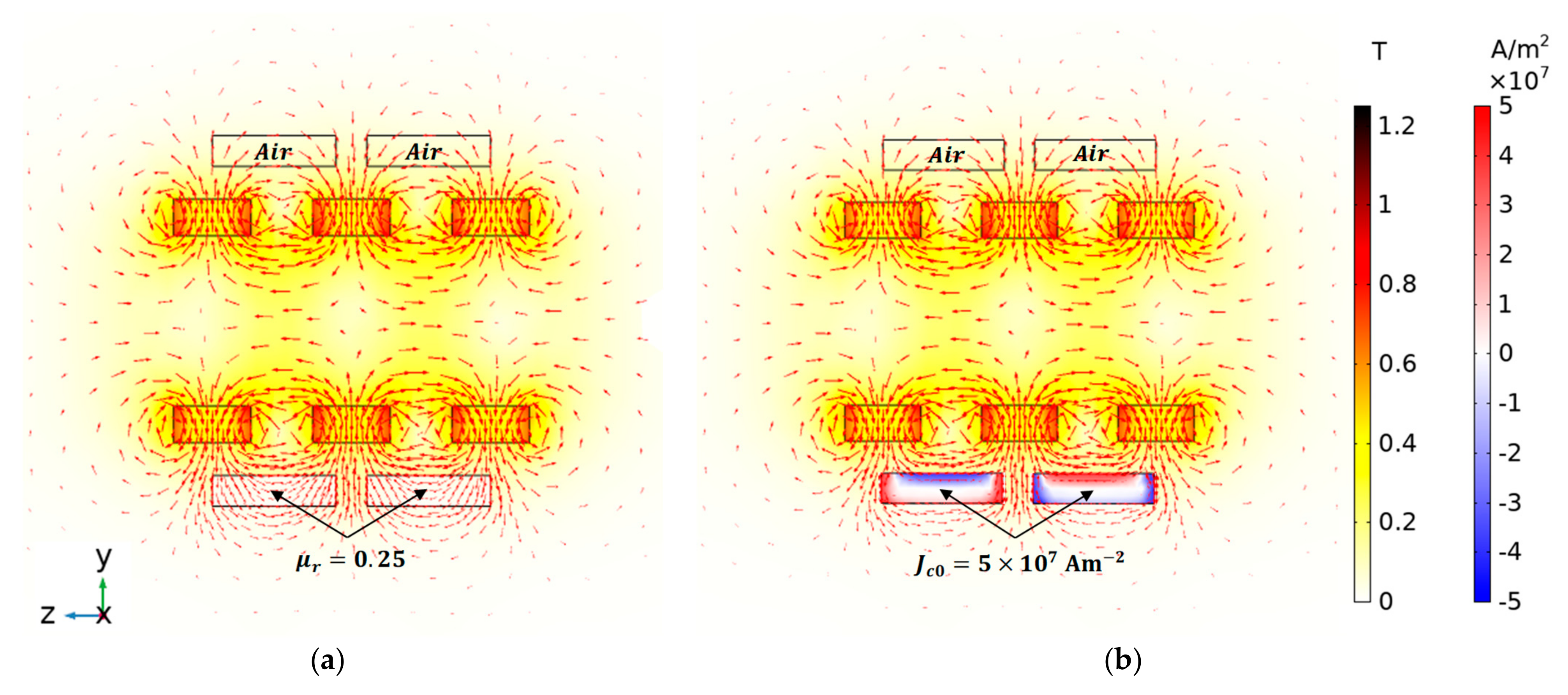
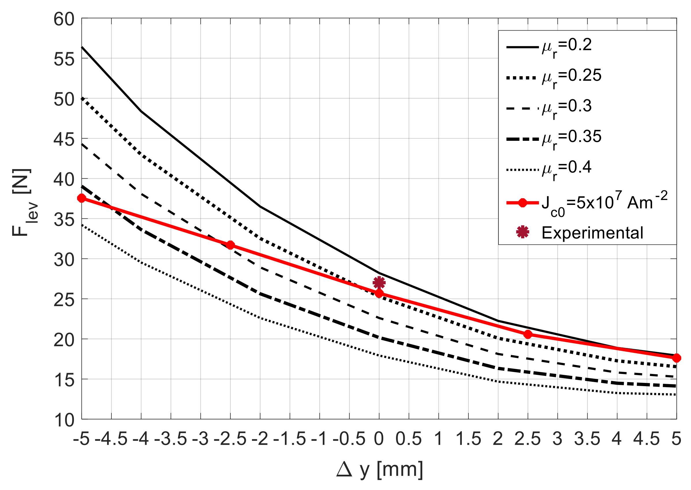
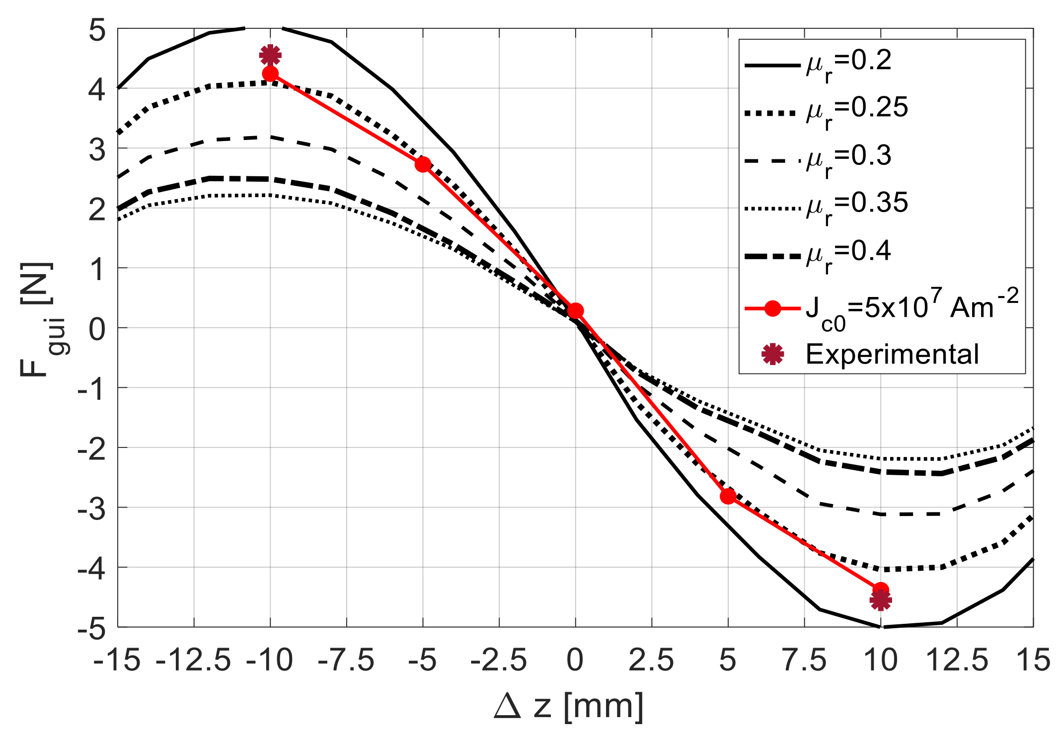
Figure 9 shows the characteristic with , predicted using 3D FEA simulations. Five were obtained considering equivalent values of ranging from to , while one (red line) was obtained using the complete electromagnetic model with .
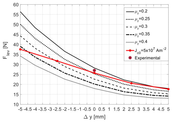
Figure 9.
Characteristic with , using Topology F and rotor D20, predicted using 3D FEA for ranging from to and for .
According to reference [23], the characteristic with , resultant from experimental measurements using rotor D20 ( = 20 mm), follows in between the two predicted using 3D FEA simulations using the complete electromagnetic model with and . The characteristic obtained considering crosses the one obtained with the complete model, considering , at almost (no vertical deviation of the rotor). Also, the experimental measurement of the levitation force at ( is close to the predicted one at the point close to , where the two characteristics for and cross each other.
Figure 10 shows the characteristic with , predicted using 3D FEA simulations. Five were obtained considering equivalent values of ranging from to , while one (red line) was obtained using the complete electromagnetic model with . The experimental measurement of the guidance force at () is close to the predicted ones, considering and .
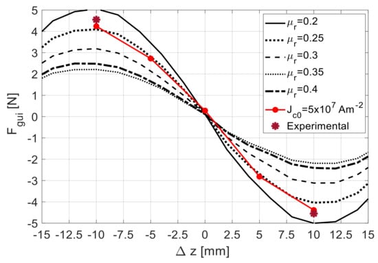
Figure 10.
Characteristic with , using Topology F and rotor D20, predicted using 3D FEA for ranging from to and for .
The radial and axial stiffness of the geometry with Topology F and rotor D20 can be calculated from the slopes of the complete EM model characteristics with (lines in red) in Figure 9 and Figure 10. Hence, for such geometry, the radial stiffness is approximately and the axial stiffness is approximately . The gravity force of rotor D20 is .
From the obtained results, one may conclude that keeping the rotor and stator axes coincident (no rotor vertical deviation ), the verified equivalent magnetic permeability remains almost constant for values of axial deviation ranging from to , assuming a value close to .
3.2. Axial Stiffness Augmentation by Adding HTS Bulks to the Stator
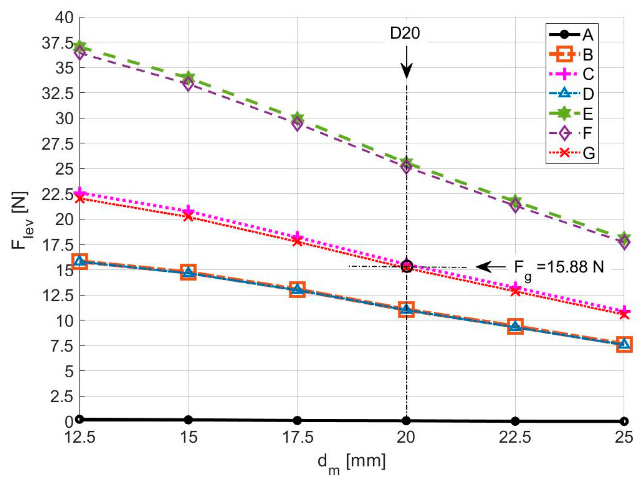
Figure 11 shows the dependence of with the distance between adjacent PM rings in the rotorobtained using 3D FEA, considering the HTS bulks with an equivalent magnetic permeability for the several topologies of HTS bulks in the stator. This keeps the rotor at the axial equilibrium position () with its axis coinciding with the stator axis ().
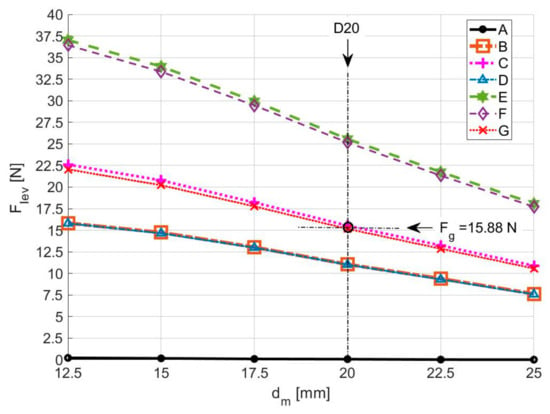
Figure 11.
Dependence of with keeping the rotor at and , for the several topologies of HTS in the stator, considering .
The levitation force decreases with the increase in the distance between adjacent PM rings in the rotor. The generated levitation assumes higher values with topologies E and F. The values of for these two topologies are close, because the HTS bulks with higher surfaces disposed vertically in Topology E almost do not contribute to levitation. The investment with Topology E, including ten HTS bulks, is higher than with Topology F, including six HTS bulks, but Topology E guarantees higher stiffness in the x-direction. A similar thinking could be applied by comparing topologies C and G. Thus, the investment with Topology C is higher than with Topology G, but Topology C guarantees higher stiffness in the x-direction. With topologies C and G, it is possible to keep rotor D20 () levitating with a vertical deviation close to , because its gravity force is .
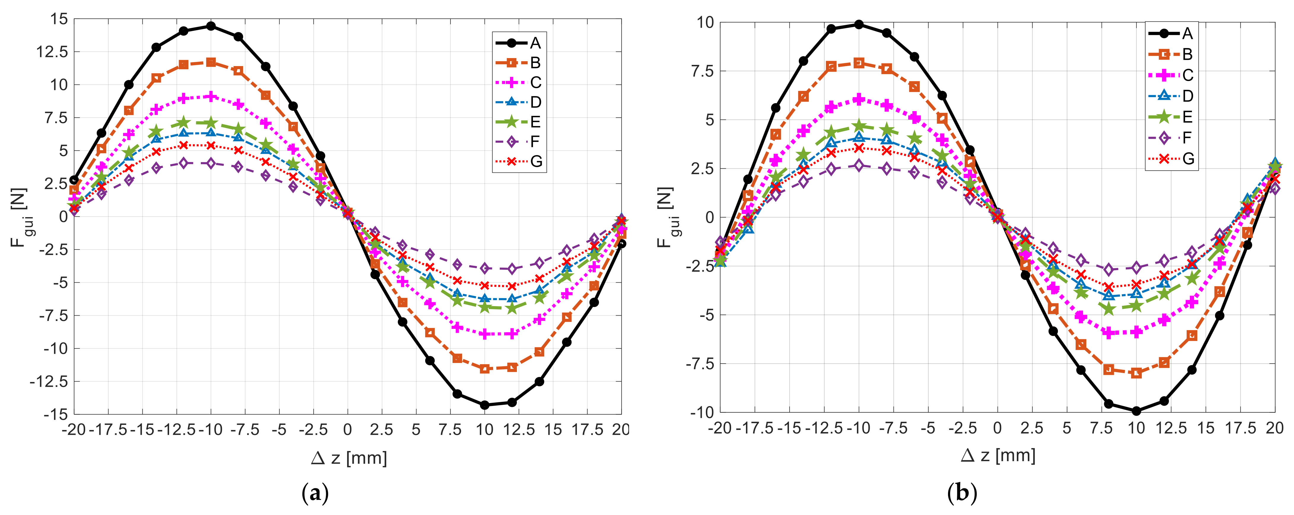
Figure 12a,b show, respectively, for rotors with and , the dependence of the guidance with the rotor axial deviation , keeping its axis coinciding with the stator axis (, obtained using 3D FEA, considering an equivalent relative magnetic permeability . This dependence was predicted for the several topologies of HTS bulks in the stator. Previous work [23] compared the guidance forces with different rotors, considering only topology F of HTS bulks.
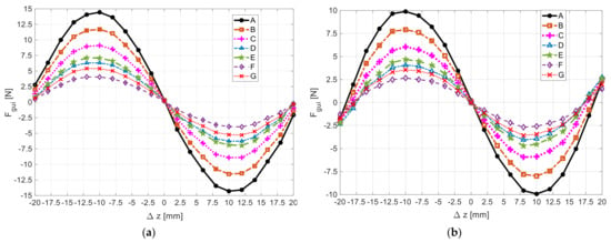
Figure 12.
Dependence of with , keeping rotors defined by (a) and (b) at , for the several topologies of HTS in the stator, predicted using 3D FEA, considering .
The guidance force is higher with than with This force depends on the number of HTS bulks in the stator, increasing with the number of HTS bulks of the considered topology.
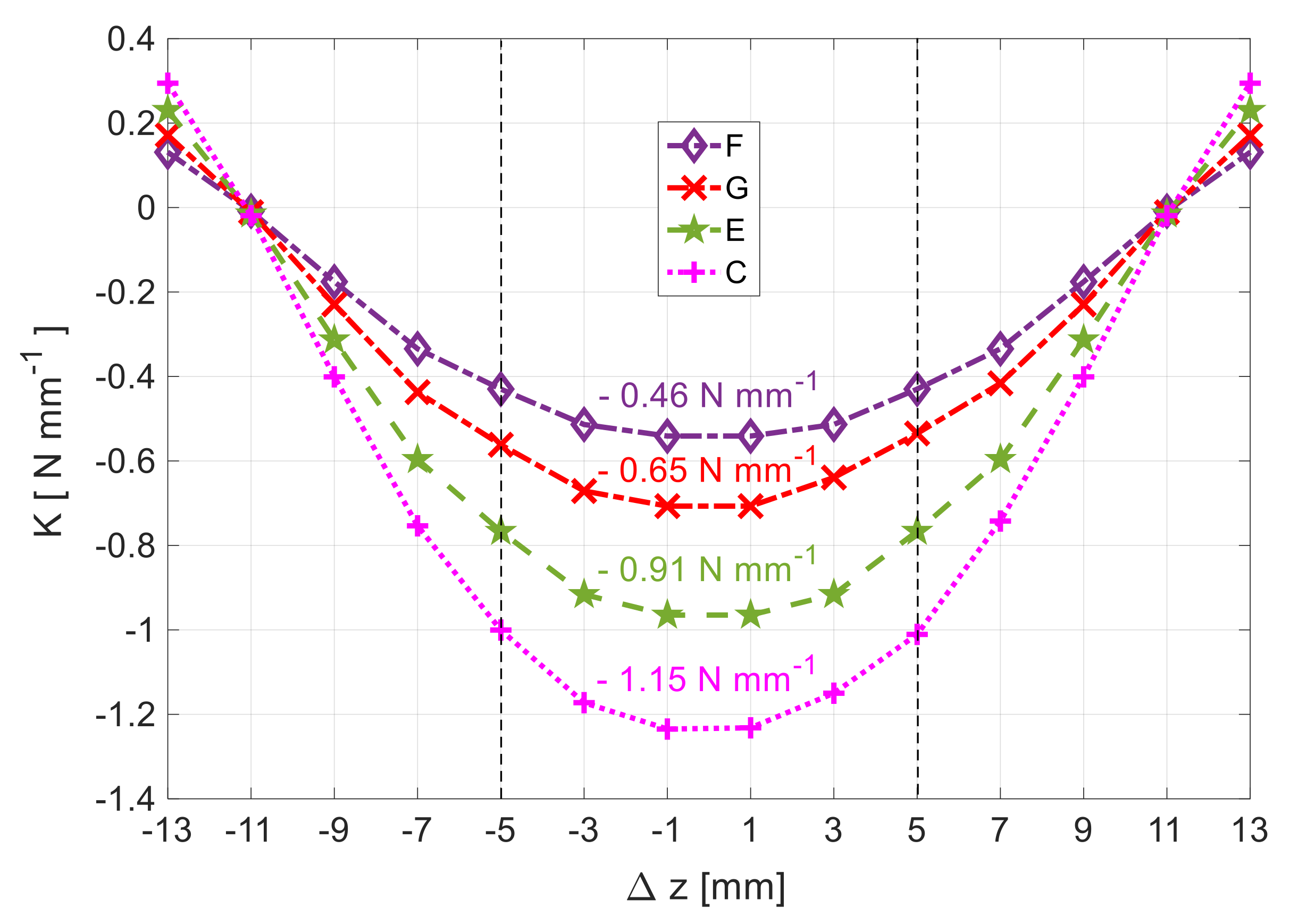
Following the methodology in [27], the axial stiffness results from deriving the guidance force relative to z. Figure 13 shows the characteristic , for geometries with rotor D20 () and topologies F, G, E, or C, highlighting the zone where the system is stable (). According to Figure 11, these four topologies of HTS bulks allow the levitation of rotor D20 with positive vertical deviation ). Figure 13 states the average values of for z in the range , where there is a higher stability and an almost stable stiffness.
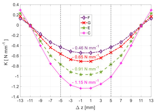
Figure 13.
Dependence of the axial stiffness on z, considering rotor D20 () and topologies F, G, E, or C.
Table 1 states the magnitudes of the average axial stiffness with rotor D20 () within , for topologies F, G, E, and C of HTS bulks in the stator, that allow the levitation of such a rotor with .

Table 1.
Axial stiffness with rotor D20 () within , for topologies F, G, E, and C of HTS bulks that allow the levitation of such a rotor with .
Previous studies considered topology F for the reasons explained in Section 2.2 and Section 3.1. With topologies C and G, the rotor would levitate at the center (with no vertical deviation) and the axial stiffness would improve, being higher for Topology C. When moving from Topology F to C, the number of HTS bulks duplicates. The axial stiffness with Topology C is still low, making the studied horizontal axis HTS ZFC radial levitation PMB inappropriate for applications requiring high-precision axial stability.
3.3. Axial Stiffness Augmentation by Adding Limiting PM Rings
The axial stiffness does not increase notably when HTS bulks are added to the stator. The addition of two limiting PM rings radially magnetized with the same polarization as the rotor edge PM rings to significantly increase the axial stiffness is evaluated here.
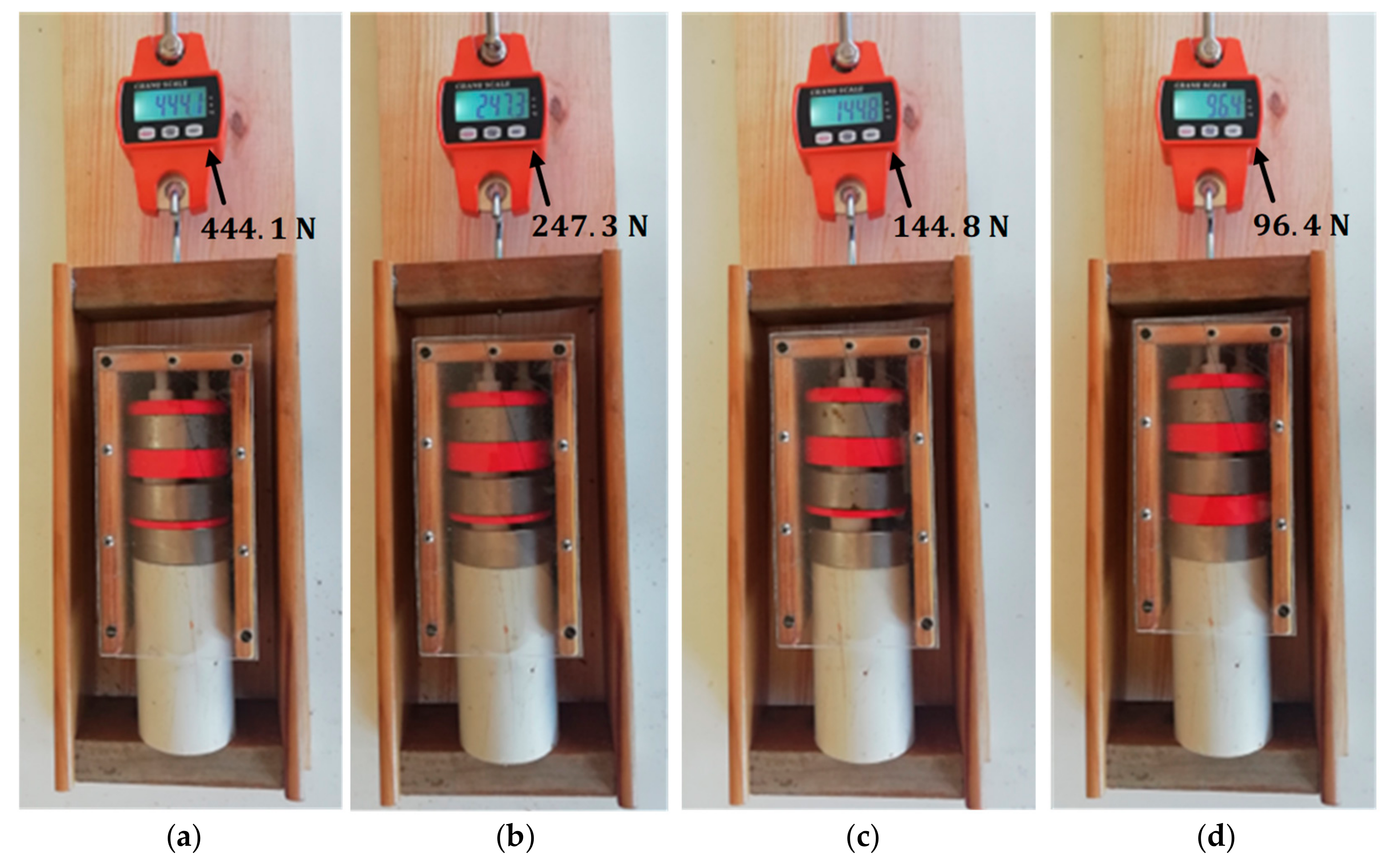
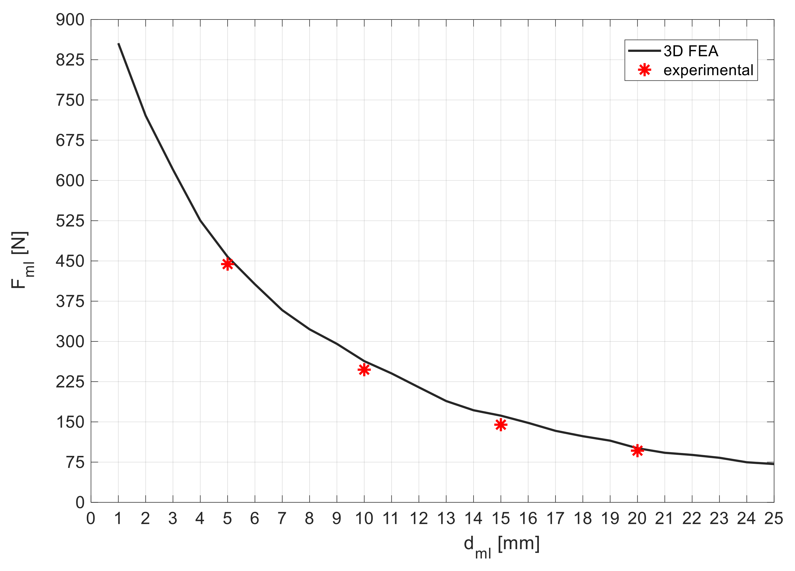
Figure 14 shows the experimental setup to measure the magnetic impulsion force between the limiting PM ring on one side and the closest rotor edge PM ring, depending on the distance in between them. Figure 15 shows measurements of , depending on being equal to (a) , (b) , (c) , and (d) . Figure 16 shows the characteristics of the magnetic impulsion force between the limiting PM ring on one side and the closest rotor edge PM ring, depending on the distance , predicted using 3D FEA and obtained experimentally. The experimental measurements follow the characteristics predicted using 3D FEA with a good approximation.

Figure 14.
Experimental setup to measure the magnetic impulsion force depending on .
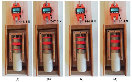
Figure 15.
Measures of with equal to (a), (b), (c), and (d).
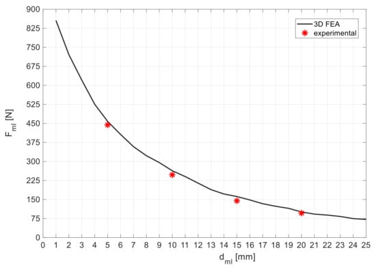
Figure 16.
Dependence of with , predicted using 3D FEA and obtained experimentally.
The total guidance force of the modified horizontal axis HTS ZFC passive bearing, including limiting PMs, results from the sum of the basic bearing guidance force with the additional guidance force from the limiting PM rings impulsion action, as expressed in Equation (1):
Dividing both members of Equation (1) by , the total guiding stiffness of the modified horizontal axis HTS ZFC passive bearingwith limiting PMs is the sum of the basic bearing guiding stiffness with the additional guiding stiffness from the limiting PMs’ impulsion action. This can be modeled by a spring that results from the parallel of two springs.
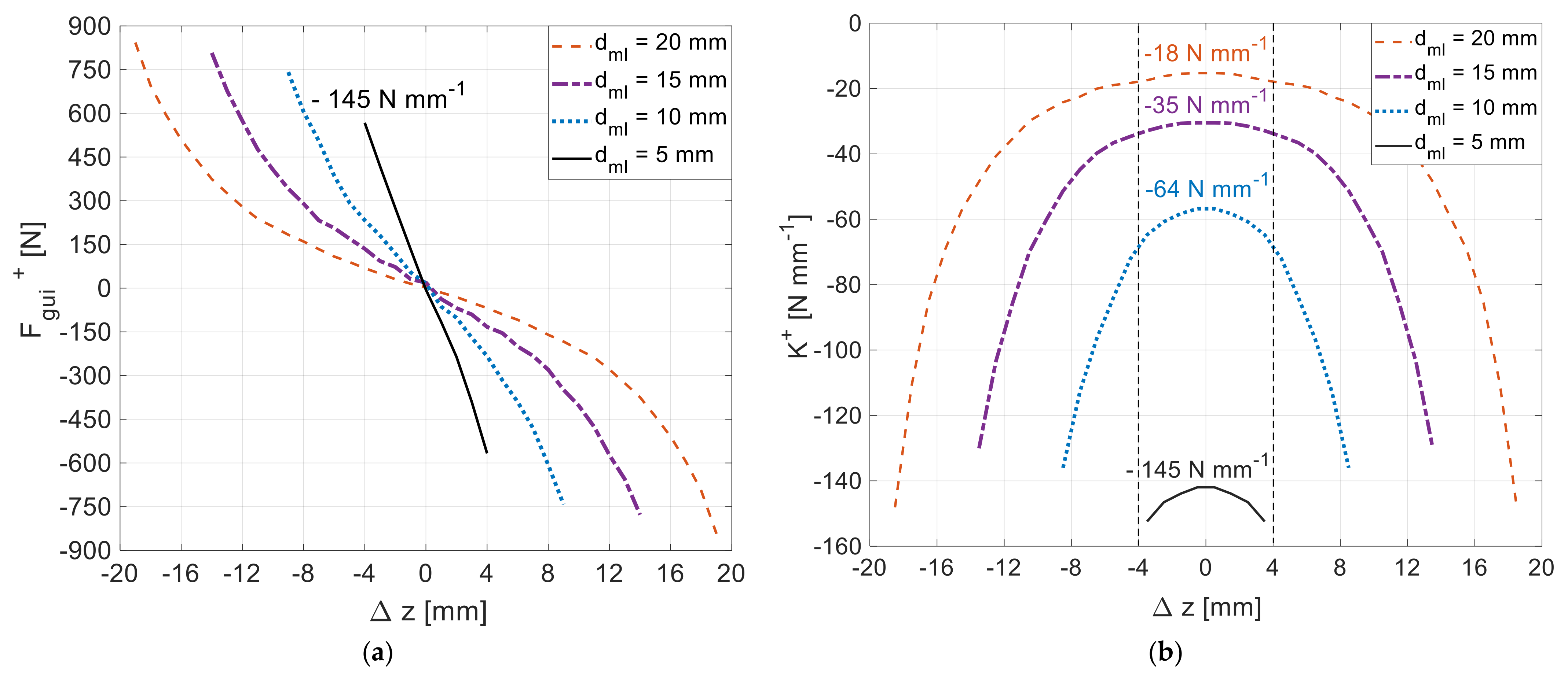
Figure 17a,b show the characteristics of the total guidance force and total axial stiffness as functions of the axial deviation for distances equal to , , and . These characteristics were predicted using 3D FEA, considering the use of rotor D20 () and the HTS bulks with an equivalent relative permeability distributed in the stator, according to Topology G. Figure 17b states the average values of the total axial stiffness within for such distances .
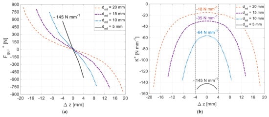
Figure 17.
Characteristics of the total guidance force (a) and total axial stiffness (b) as functions of the axial deviation ∆z, considering the use of rotor D20 () and the HTS bulks with an equivalent relative permeability distributed in the stator, according to Topology G.
With limiting PM rings placed at a distance from the rotor edge PM rings, the magnitude of the average total predicted axial stiffness within would be . This value is significantly higher (more than one hundred times) than the one presented in Table 1 for Topology G without limiting PM rings
4. Discussion
With the addition of HTS bulks in the stator, magnetic guidance forces increase, but magnetic levitation forces decrease. Topology F, with only six HTS bulks at the bottom of the stator, is the one that guarantees higher levitation but, on the other hand, is the more unstable topology. Because Topology F enables a wider range of vertical deviations for testing, this topology was used to predict and evaluate the HTS bulks’ equivalent relative permeability as a function of the rotor vertical deviation.
According to Figure 11, with topologies C, E, F, and G of HTS bulks in the stator, the PM rotor D20 can levitate at vertical deviations . When moving from Topology F to Topology E, the levitation remains the same, but the guidance force increases by about . Topologies C and G provide almost equal levitation forces, about of the levitation with topologies E and F. With topologies C and G, the rotor is kept levitating at the center (with no vertical deviation). The guidance force with topologies C and G are about and higher than with Topology F, respectively. Hence, when moving from Topology F to Topology G, with only two more HTS bulks, the levitation is reduced to and the guidance increased about compared to topology F. When moving from Topology F to Topology C, six additional bulks are needed, representing a significative investment, to obtain a guidance increase that is insufficient for applications requiring high-precision axial stability.
To facilitate the process of ZFC, after the cryocooling of HTS bulks far from the influence of the rotor magnetic fields, the rotor should be placed in the center of the stator cavity, with the rotor and stator axes aligned. Due to the existing symmetry, the same initial induced current distribution and level of magnetization is expected for all HTS bulks, independent of their azimuthal position. This would imply that if all the HTS bulks are kept at the same temperature and the rotor kept levitating at the center (with no vertical deviation), the magnetic field penetration and electromagnetic losses are approximately the same on all the HTS bulks, independent of their azimuthal position. The results from references [21,22] have shown that when the level of LN2 is kept above that of the HTS bulks domain, their average temperature stays close to the average LN2 temperature. If, after ZFC, the rotor levitates with eccentricity, the electromagnetic losses in operation will be higher in the bulks closer to the rotor. In the case of the considered experimental prototype, according to Figure 11, the rotor levitates at the center in the cases of Topologies C and G. Because of the levitation symmetry with these two topologies, the losses will be almost the same on all HTS bulks, independent of their azimuthal position. In the cases of Topologies B and D, the rotor levitates with negative vertical deviation (), with the expected losses in the six bottom bulks being higher. In the cases of Topologies E and F, the rotor levitates with positive vertical deviation (), with the expected losses in the six bottom bulks being lower. Hence, it is expected that, in the considered experimental prototype, the operating electromagnetic losses increase according to the following topology order , where represents the losses with Topology F.
With the passive addition of two limiting PM rings, the axial stiffness increases significantly (more than one hundred times), considering a distance between limiting PM rings and rotor side PM rings equal to . This enables the use of the modified HTS ZFC bearing for high-precision axial stability applications.
5. Conclusions
The base geometry of the horizontal axis HTS ZFC radial passive magnetic bearing generates guiding stability, when the distance between the rotor side PM rings is higher than the distance between the edges of discontinuous HTS bulk rings in the stator [23]. The values of generated guidance forces by the basic geometry do not permit their application for high-precision axial stability applications such as precision gyroscopes, horizontal axis propellers, and turbines. The results presented in this study have shown that, with the addition of HTS bulks in the stator, which is slandered by a relevant cost increase, the guidance forces do not increase significantly, remaining of the same order and still cannot be used for high-precision axial stability applications.
A proposed modification consists of adding two limiting PM rings, placed at a fixed distance from the rotor edges, considering no rotor axial deviation, and with the same polarization as the rotor side PM rings. The results show that for a distance between limiting PM rings and rotor side PM rings equal to , the magnitude of the total axial stiffness is , which is more than one hundred times higher than the axial stiffness for the base geometry . With such a modification, the HTS ZFC radial passive bearing may be used in applications of high-precision axial stability.
Author Contributions
Conceptualization, A.J.A.C. and P.J.C.B.; methodology, A.J.A.C. and J.F.P.F.; software, A.J.A.C. and J.F.P.F.; validation, A.J.A.C., J.F.P.F. and P.J.C.B.; formal analysis, J.F.P.F. and P.J.C.B.; investigation, A.J.A.C.; resources, P.J.C.B.; data curation, A.J.A.C. and J.F.P.F.; writing—original draft preparation, A.J.A.C.; writing—review and editing, A.J.A.C., J.F.P.F. and P.J.C.B.; supervision, J.F.P.F. and P.J.C.B.; project administration, J.F.P.F. and P.J.C.B.; funding acquisition, J.F.P.F. and P.J.C.B. All authors have read and agreed to the published version of the manuscript.
Funding
This research was funded by Fundação para a Ciência e a Tecnologia (FCT) via the project LAETA Base Funding (DOI: 10.54499/UIDB/50022/2020).
Data Availability Statement
The data presented in this study are available on request from the corresponding author. The data are not publicly available due to privacy.
Conflicts of Interest
The authors declare no conflicts of interest.
References
- Sivrioglu, S.; Basaran, S.; Yildiz, A.S. Multisurface HTS-PM Levitation for a Flywheel System. IEEE Trans. Appl. Supercond. 2016, 26, 3603206. [Google Scholar] [CrossRef]
- Ma, K.B.; Chen, Q.Y.; Postrekhin, E.; Ye, H.; Zhang, Y.; Chu, W.K. High temperature superconductor levitation bearings for space application. Phys. C Supercond. 2000, 341–348, 2517–2520. [Google Scholar] [CrossRef]
- Anischenko, I.V.; Pokrovskii, S.V.; Rudnev, I.A. Simulation of thrust magnetic bearings for levitation systems. Phys. Conf. Ser. 2019, 1590, 012061. [Google Scholar] [CrossRef]
- Hossain, M.; Abdkader, A.; Cherif, C.; Sparing, M.; Berger, D.; Fuchs, G.; Schultz, L. Innovative twisting mechanism based on superconducting technology in a ring-spinning system. Text. Res. J. 2014, 84, 871–880. [Google Scholar] [CrossRef]
- Deng, Z.; Zheng, J.; Lin, Q.; Li, J.; Zhang, Y.; Wang, S.; Wang, J. Improved Maglev Performance of Bulk High-Temperature Superconductors with a Re-magnetization Process After Zero-Field Cooling. J. Low. Temp. Phys. 2011, 162, 72–79. [Google Scholar] [CrossRef]
- Li, S.L.; Wen, H.H.; Zhao, Z.X. Modeling and simulation on the magnetization in field-cooling and zero-field-cooling processes. Phys. C Supercond. 1999, 316, 293–299. [Google Scholar] [CrossRef]
- Yang, W.M.; Zhou, L.; Feng, Y.; Zhang, P.X.; Nicolsky, R.; de Andrade, R. The characterization of levitation force and attractive force of single-domain YBCO bulk under different field cooling process. Phys. C Supercond. 2003, 398, 141–146. [Google Scholar] [CrossRef]
- Fujishiro, H.; Naito, T. Simulation of temperature and magnetic field distribution in superconducting bulk during pulsed field magnetization. Supercond. Sci. Technol. 2010, 23, 105021. [Google Scholar] [CrossRef]
- Arnaud, J.; Branco, P.J.C. Electrothermal characteristics of YBCO bulk magnets deep in LN2: A preliminary analysis for its use as excitation system of low-speed synchronous generators. IEEE Trans. Appl. Supercond. 2016, 26, 6800608. [Google Scholar] [CrossRef]
- Ceniga, L.; Diko, P. Matrix crack formation in Y–Ba–Cu–O superconductor. Phys. C Supercond. 2003, 385, 329–336. [Google Scholar] [CrossRef]
- Diko, P.; Krabbes, G. Formation of c-macrocracks during oxygenation of TSMG YBa2Cu3O7/Y2BaCuO5 single-grain superconductors. Phys. C Supercond. 2003, 399, 151–157. [Google Scholar] [CrossRef]
- Rastogi, A.; Coombs, T.A.; Campbell, A.M.; Hall, R. Axial Stiffness of Journal Bearings in Zero-Field and Field-Cooled Modes. IEEE Trans. Appl. Supercond. 2005, 15, 2242–2244. [Google Scholar]
- AlizadehTir, M.; Marignetti, F.; Mirimani, S.M. Axial Flux Machine Using Passive Magnetic Bearing with Axial Magnetization. In Proceedings of the 2018 International Symposium on Power Electronics, Electrical Drives, Automation and Motion, Amalfi, Italy, 20–22 June 2018; pp. 1–6. [Google Scholar]
- Lee, J.-Y.; Nam, G.-D.; Yu, I.-K.; Park, M. Design and Characteristic Analysis of an Axial Flux High-Temperature Superconducting Motor for Aircraft Propulsion. Materials 2023, 16, 3587. [Google Scholar] [CrossRef]
- Zhu, Y.; Li, Q.; Xu, D.; Zhang, M. Modeling of Axial Magnetic Force and Stiffness of Ring-Shaped Permanent-Magnet Passive Vibration Isolator and Its Vibration Isolating Experiment. IEEE Trans. Magn. 2012, 48, 2228–2238. [Google Scholar] [CrossRef]
- Sun, J.; Chen, D.; Ren, Y. Stiffness Measurement Method of Repulsive Passive Magnetic Bearing in SGMSCMG. IEEE Trans. Instrum. Meas. 2013, 62, 2960–2965. [Google Scholar] [CrossRef]
- Li, W.; Yang, T.; Xin, Y. Principle, Modeling and Experiment of a New Axial-Type Superconducting Magnetic Bearing with Superconducting Coil. IEEE Trans. Appl. Supercond. 2024, 34, 3601705. [Google Scholar] [CrossRef]
- McDonald, A.; Jaen-Sola, P. A Stiffness Approach for Coupling Structural and Magnetic Models for the Sustainable Design, Optimisation and Real-Time Structural Integrity Assessment of Radial Flux Permanent Magnet Generators for Direct-Drive Wind Turbines. Sustainability 2024, 16, 2393. [Google Scholar] [CrossRef]
- Sun, Y.; Meng, K.; Yuan, S.; Zhao, J.; Xie, R.; Yang, Y.; Luo, J. Modeling Electromagnetic Force and Axial-Stiffness for an Electromagnetic Negative-Stiffness Spring Toward Vibration Isolation. IEEE Trans. Magn. 2019, 55, 8000410. [Google Scholar]
- Arsénio, A.J.; Roque, M.; Cardeira, C.; Branco, P.J.C.; Melicio, R. Prototype of a Zero-Field-Cooled YBCO Bearing with Continuous Ring Permanent Magnets. IEEE Trans. Appl. Supercond. 2018, 28, 5207407. [Google Scholar] [CrossRef]
- Arsénio Costa, A.J.; Fernandes, J.F.P.; Melicio, R.; Cardeira, C.; Costa Branco, P.J. Numerical and Experimental Analysis of the ZFC Heat Release from a YBCO Bulk and Validation of YBCO Thermal Parameters. Crystals 2023, 13, 532. [Google Scholar] [CrossRef]
- Costa Arsénio, A.J.; Costa Branco, P.J. Thermo-Hydraulic Analysis of a Horizontal HTS ZFC Levitating Bearing Concerning Its Autonomy Safety Service Time. IEEE Trans. Appl. Supercond. 2021, 31, 3602010. [Google Scholar]
- Arsénio, A.J.; Silva, F.F.; Fernandes, J.F.P.; Branco, P.J.C. Optimization of the Guiding Stability of a Horizontal Axis HTS ZFC Radial Levitation Bearing. Actuators 2021, 10, 311. [Google Scholar] [CrossRef]
- Peixoto, I.S.P.; da Silva, F.F.; Fernandes, J.F.P.; da Costa Branco, P.J. 3D Equivalent Space-Varying Permeability Model of HTS Bulks for Computation of Electromagnetic Forces. IEEE Trans. Appl. Supercond. 2021, 31, 3600907. [Google Scholar] [CrossRef]
- Hong, Z.; Campbell, H.M.; Coombs, T.A. Computer Modeling of Magnetisation in High Temperature Superconductors. IEEE Trans. Appl. Supercond. 2007, 17, 3761–3764. [Google Scholar] [CrossRef]
- Zhang, M.; Coombs, T.A. 3D modeling of high-Tc superconductors by finite element software. IOP Supercond. Sci. Technol. 2012, 25, 015009. [Google Scholar] [CrossRef]
- Marignetti, F.; Tir, M.A.; Mirimani, S.M. An axial passive magnetic bearing using three PM rings. IET Electr. Power Appl. 2021, 15, 415–428. [Google Scholar] [CrossRef]
Disclaimer/Publisher’s Note: The statements, opinions and data contained in all publications are solely those of the individual author(s) and contributor(s) and not of MDPI and/or the editor(s). MDPI and/or the editor(s) disclaim responsibility for any injury to people or property resulting from any ideas, methods, instructions or products referred to in the content. |
© 2024 by the authors. Licensee MDPI, Basel, Switzerland. This article is an open access article distributed under the terms and conditions of the Creative Commons Attribution (CC BY) license (https://creativecommons.org/licenses/by/4.0/).

