Abstract
This study proposes a robust geometric controller tailored for quadrotor unmanned aerial vehicles (UAVs). The original geometric controller exhibits excellent performance in quadrotor UAV maneuvers. However, as a model-based nonlinear control method, it is sensitive to system model parameters. By integrating a novel extended Kalman filter (EKF)-based estimator for real-time, online estimation of the quadrotor’s inertia parameters, the controller adeptly handles internal uncertainties and external perturbations during flight maneuvers. This approach significantly improves the robustness of the control system against model inaccuracies. Empirical evidence is provided through both simulation and extensive real-world flight tests, demonstrating the controller’s effectiveness and its practical applicability in dynamic environments. The results confirm that this integration substantially enhances system reliability and performance under varied operational conditions.
1. Introduction
In recent years, quadrotor UAVs have become a central focus of research due to their simplicity, cost-effectiveness, and adaptability, finding applications in diverse fields such as commercial light shows, search and rescue operations [1], transportation [2], and agriculture [3]. In order to ensure the successful implementation of these applications, quadcopter UAVs need to have good maneuverability and agility, and an effective controller plays a crucial role in this.
Among effective controllers, linear control approaches like the PID [4] and LQR [5] are particularly valued for their structural simplicity and straightforward deployment, seeing broad utilization across quadrotor UAVs. Nonetheless, inherent limitations, such as the small-angle approximation used for model linearization, typically limit these methods to exhibiting merely local theoretical stability. Therefore, nonlinear controllers, including sliding mode control [6] and backstepping [7], have been pursued for application on quadrotor UAVs. However, these methods inevitably encounter singularity and ambiguity challenges. Lee et al. [8] have proposed a coordinate-free geometric controller developed on the SE(3) manifold, utilizing rotation matrices for attitude representation. This method effectively circumvents the aforementioned issues and achieves near-global exponential stability, making it extensively applicable in maneuverability scenarios of UAVs.
Numerous studies on geometric controllers have emerged in recent decades. In Ref. [9], an extended Kalman filter developed on SE(3) was designed to estimate states during sensor failure or in GPS-denied environments. To enhance UAV safety in complex environments, the study in [10] integrated a control barrier function (CBF) into the geometric control framework. This approach ensures UAV safety by defining a protected region through the CBF and modifying control inputs with quadratic programming (QP), thereby allowing for UAV operation within this region without compromising safety constraints. Moreover, the issue of disturbances during flight was tackled in [11,12]. A finite-time disturbance observer was integrated into a geometric controller and was capable of estimating disturbances with unknown bounds within a finite time. In Ref. [12], the researchers employed an extended state observer (ESO) to estimate not only external disturbances but also internal uncertainties in the quadrotor UAV system. Furthermore, the studies in [13,14] primarily focused on the application of geometric controllers in payload transportation. In Ref. [13], a sophisticated geometric control strategy was implemented, managing dual-loop control for effective trajectory tracking and swing angle stabilization in quadrotor UAVs with suspended loads. The researchers in [14] tackled the challenges posed by elastic cables in similar UAV setups by using geometric control techniques combined with the singular perturbation theory to simulate a system with inelastic cables, thus enhancing control precision.
However, these SE(3) geometric controllers rely on accurate modeling of the quadrotor UAV, which is difficult to measure and may even change due to external influences or changes in load [15]. Large deviations between measured model parameters and their true values can affect the flight performance of a quadrotor UAV, and may even lead to controller divergence. Traditional methods for parameter calibration, such as CAD modeling and frequency domain analysis [9,15], which typically depend on predetermined models and offline testing, are complex and struggle to provide real-time responses to environmental uncertainties and internal dynamic modifications. Current precise modeling methods typically utilize inputs and outputs, usually the rotational speeds of four rotors and measurements from onboard sensors for quadrotor UAVs, to model a system’s dynamic characteristics. To accurately model quadrotor UAVs, machine learning methods have been extensively applied [16,17]. These techniques primarily enable offline estimation of a quadrotor UAV’s dynamic model based on pre-sampled datasets. Other time-domain methods, including recursive least squares (RLSs) [18], maximum likelihood [19], Bayesian filtering [15,20,21,22], and sliding mode observer [23], are also widely utilized. The estimated parameters typically encompass mass, inertia matrix, and aerodynamic coefficients, all of which significantly influence control performance.
Due to the inherent noise in sensor measurements on quadrotor UAVs, methods such as those described in [18,19] start by using a Kalman filter (KF) to preprocess the flight data before identification. In Ref. [18], the researchers initially filtered out sensor noise and then employed RLSs to estimate the observable parameters. The work in [19] utilized an improved preprocessing method, Flight Path Reconstruction (FPR), which integrated the EKF and a Rauch–Tung–Striebel smoother. Then, maximum likelihood estimation was used to identify the system model. In addition to the estimation of inertia parameters, the studies in [21,22] utilized Bayesian filtering methods, such as the EKF and unscented Kalman filter (UKF), to estimate the quadrotor system’s geometric parameters, including the position of the center of mass (CoM) and the orientations of onboard sensors and rotors, significantly reducing the geometric assumptions commonly found in related research.
The researchers in [15,24,25] focus on modeling aerodynamic effects. Specifically, in [15], the UKF was utilized for online estimation of the drag-force coefficients and external wind conditions, enhancing the drone’s capability to reject gusts. In Ref. [24], the researchers only employed an inertial measurement unit (IMU) and motor speeds to estimate inertia parameters and model the blade-flapping moment. The experiments validated that blade-flapping modeling effectively improves estimations of the moment of inertia. In Ref. [25], the behavior and responses of asymmetric quadrotor UAVs under complex aerodynamic effects were discussed in detail, with the KF method applied for system identification. The stable convergence of recursive methods, such as gradient descent and least squares, requires persistence of the excitation conditions. In Ref. [26], the researchers employed the dynamic regressor extension and mixing (DREM) technique. By preprocessing the regressor both algebraically and dynamically, the persistence of excitation constraints was effectively alleviated.
In this article, a robust geometric controller is introduced, integrating the geometric controller with an online EKF-based estimator to estimate the UAV’s inertia parameters. The contributions of this paper are summarized as follows:
- (1)
- A novel control scheme is presented for a quadrotor UAV that incorporates an online estimation of inertia parameters. This enables the system to effectively address uncertainties during maneuvers, enhance robustness, and improve performance in diverse operating environments.
- (2)
- By leveraging the equivalence between quaternions and rotation matrices, the proposed approach represents attitude with quaternions within the EKF parameter estimator. Compared to the rotation matrix representation, this significantly reduces estimation dimensions and computational time while maintaining effective control performance.
- (3)
- The effectiveness of the proposed scheme is validated through both simulations and real-world experiments, demonstrating superior performance compared to the traditional geometric controller. The real-world experiment can be viewed online at https://youtu.be/p4RYlQRqmow (accessed on 27 May 2024).
The organization of this paper is as follows: Section 2 illustrates the dynamic model of quadrotor UAVs, accompanied by an analysis of system observability across various sensor configurations. Section 3 details the implementation of a parameter estimation algorithm utilizing the EKF as well as the architecture of the geometric controller. Section 4 showcases the efficacy of the proposed control scheme through both simulations and experiments.
2. Quadrotor System Model
2.1. Quadrotor Dynamics
This section elaborates on the dynamic model of the quadrotor UAV. As illustrated in Figure 1, the quadrotor in the × configuration is chosen to demonstrate the principles. The inertial reference frame and the body-fixed frame are introduced to clarify the description, represented by and , respectively. It is assumed that the four rotors of the quadrotor UAV are positioned on the plane spanned by and . Additionally, the CoM of the quadrotor UAV aligns with the origin of the body-fixed frame, simplifying the dynamics analysis.
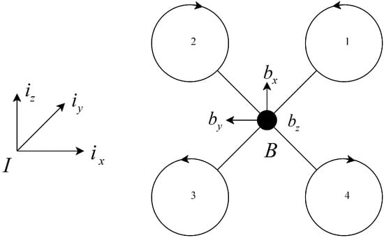
Figure 1.
The definition of the coordinate system and rotor numbering regarding the quadrotor model used in this article.
The rotor i generates a thrust and a torque , both aligned along , for . Simplifying the complex aerodynamic effects, the thrust can be given by , where is the lift coefficient and is the rotation speed of the i-th rotor [15]. The torque is directly proportional to the thrust, which can be represented by , with representing the proportionality constant. The perpendicular distances from the center of rotor i to and are denoted by and , respectively. The total thrust f and the total moment can be calculated from the following equation:
The state of a quadrotor UAV is characterized by its position , velocity , attitude , and angular velocity , where the rotation matrix R represents the orientation of the body-fixed frame with respect to the inertial reference frame and the is expressed in the body-fixed frame. As the position and attitude of the quadrotor are, respectively, represented in and , the configuration manifold of the quadrotor is the special Euclidean group [8]. The mass and inertial matrix of the quadrotor are denoted by and , where refers to the operation of converting a vector into its corresponding symmetric matrix form. Therefore, according to Newton’s second law and the Newton–Euler equations, the dynamic model of a quadrotor can be represented as follows:
where , is the gravity, and is the map from to . For , is given by
The geometric controller implemented on the SE(3) manifold circumvents the singularities of Euler angles and the ambiguities of quaternions. However, when it comes to state and parameter estimation, utilizing the rotation matrix to represent attitude significantly augments the estimation dimension, leading to increased computational complexity and challenges in achieving estimation convergence. To avoid the long-term singularity issues in attitude estimation [27], quaternions are employed to represent rotation during the estimation process. The estimated quaternion is subsequently converted into an equivalent rotation matrix to calculate the control inputs. This transformation theoretically preserves the performance of the controller. Let the quaternion denote the same rotation as R, Equation (3) can also be represented as follows:
The state space representation of the quadrotor dynamics is formulated as , where
is the state vector and is the control input. A primary objective of this study is to estimate the mass and inertial matrix of the quadrotor system. Consequently, in our model, these inertia parameters are no longer considered constants in the traditional sense. We define as the parameter vector, which is considered to have zero dynamics, and as the extended state vector. Thus, the full dynamics is as follows:
2.2. Observability Analysis
In control systems, observability denotes the ability to uniquely determine complete information on the internal state of a system through its outputs. The observability of nonlinear systems can be contingent upon the system’s initial conditions and the specific trajectories of inputs. This implies that a system may exhibit observability under certain conditions while becoming unobservable under others, a characteristic distinct from linear systems. Consequently, the analytical methods employed for observability assessment in linear systems are not directly applicable to their nonlinear counterparts. In this section, we first introduce the common measurement configurations utilized for quadrotor UAVs and subsequently employ a differential geometric approach to analyze the observability of the system.
Sensors are key components that enable quadrotor UAVs to achieve stable flight and navigation. These sensors, including GPS receivers, IMUs, optical flow sensors, ultra-wideband (UWB) systems, and motion capture systems [21], are either directly mounted on the quadrotor UAV or deployed within the flight area. These sensors are categorized into two types based on the measurements they provide: pose sensors and IMUs [22]. Pose sensors offer data on the position and attitude of a quadrotor UAV, while IMUs provide measurements of angular velocity and acceleration. Assuming that the installation orientations of both pose sensors and IMUs align with the body-fixed frame, the measurement equations for both are as follows:
Herein, denotes the bias of the pose sensor relative to the body frame, which is assumed to be known. and , respectively, represent the measurements from the pose sensor and the IMU.
The observability of nonlinear systems can be evaluated by constructing an observability matrix and examining its rank. If , the system can be considered locally weakly observable [22]. Given the system’s measurement equation , the observability matrix can be calculated using Lie derivatives:
with
The dimension of the observability matrix is , and its rank can be computed numerically using symbolic computation libraries. It is important to note that the attitude q is represented by quaternions, with the inherent constraint , where is the conjugate of q. Numerical calculations demonstrate that all elements in the extended state vector are locally weakly observable, regardless of the measurement configuration employed.
3. Robust Geometric Controller
3.1. EKF Estimator
The analysis of observability in Section 2 demonstrates that the quadrotor system is observable under certain measurement conditions. This observability allows for estimations of the system’s state and parameters using a series of measured values. The EKF is an advanced signal-processing algorithm used to estimate the states or parameters of nonlinear dynamic systems from a series of incomplete and noisy measurements [9]. As an extension of the classic Kalman filter, the EKF is applicable to quadrotor systems, which exhibit pronounced nonlinear characteristics. This section applies the EKF algorithm to the quadrotor system illustrated in Section 2 and presents detailed steps for online parameter estimation.
The EKF algorithm typically involves two phases: Initially, it calculates the current state’s estimate and covariance based on the state transition function, with the prior state’s optimal estimate and covariance as inputs. Subsequently, the Kalman gain is computed based on the measurement model. This gain is then used, along with measurement data, to update the estimate of the state and its covariance, thereby establishing the current optimal estimate. To apply the EKF algorithm, the dynamic Equation (8) is discretized into the state transition form:
where represents the different form of , and denotes the additive noise within the state transition.
In practical applications, it is challenging to obtain a perfect model that accurately describes a quadrotor system’s dynamic behavior. Additive noise can aid in compensating for a model’s uncertainty, enhancing the filter’s robustness. Moreover, the randomness of external environments also impacts a system’s state transitions. Additive noise can simulate this randomness under such conditions, making the state estimation more closely aligned with actual scenarios.
Let and , respectively, be the optimal estimates of the mean and covariance of at time k, and be the covariance of w. In actual quadrotor systems, the input force and torque, typically derived from motor PWM signals and simplified models of thrust and aerodynamics, are not measured directly. Consequently, substantial noise is inevitably introduced. Let represent the covariance of the system input u.
For the prediction phase,
with
The measurement model is represented by , where z denotes sensor measurements and v is the measurement error, which is characterized as white noise with a mean of zero and a covariance of R. The dimensions of z and v depend on the measurement configuration. Then, the equations of the update phase are given by
with
With the initial values, noise covariance, and observation data appropriately configured, the EKF algorithm will, in theory, recursively estimate the current state and parameters.
3.2. SE(3) Geometric Controller
Quadrotor UAVs often experience significant changes in pose within a short period during maneuvering flight, a scenario that current linear PID controllers struggle to manage effectively. The geometric controller configures the UAV on the SE(3) manifold, effectively avoiding the ambiguity and singularity issues arising from quaternion or Euler angle representations of attitude. This approach also fully leverages the system model, making it well suited for the maneuvering flight of UAVs.
Quadrotor UAVs, with six degrees of freedom in motion and only four control inputs, are inherently underactuated systems. This underactuation limits their ability to simultaneously track both position and attitude commands. This study primarily focuses on the trajectory tracking performance of quadrotor UAVs, with the control variables being their desired position and the orientation of the axis , denoted as and , respectively. The position and velocity tracking errors, represented as and , can be derived as follows:
Referring to the translational dynamic model presented in Section 2, we can derive an approximate form of the desired thrust:
where is the estimate of mass m, and and are positive definite symmetric matrices. The desired orientation of and is defined as follows:
Then, the desired attitude is
Compared to the form of attitude error proposed in [8], Invernizzi et al. [11] introduced the left value, defined as
which simplifies the final controller structure. The attitude error function on SO(3) is defined as
where represents the trace of the matrix. Defining to be the map from SO(3) to , the attitude error in the SO(3) form, , is as follows:
Given that and reside in different tangent spaces, we convert into the tangent space of :
Consequently, the velocity error in the SO(3) form can be chosen as
Let be the estimate of the inertial matrix. Based on the preceding definitions of tracking errors, the controller can ultimately be derived as follows:
where is a positive definite symmetric matrix. Given that a quadrotor UAV can only generate thrust perpendicular to the plane of the body directed upwards, the final desired thrust is taken as . The stability of the complete system is illustrated in the subsequent analysis.
Theorem 1.
The zero equilibrium point of the closed-loop attitude error system maintains stability prior to the inertia matrix estimation error converging to zero. Following this convergence, it transitions to exhibiting exponential stability.
Proof of Theorem 1.
The Lyapunov candidate is chosen as
where is a positive constant. For the derivatives of the attitude tracking errors,
where is the estimation error of the inertia matrix. is artificially set to have boundaries throughout the entire estimation. Defining , it can be concluded that is bounded by limiting the . Then, the derivate of the Lyapunov function is
where and represent the minimum and maximum eigenvalues of a matrix. Let ,
with
Finally, it can be derived as
As the estimation of the inertial matrix converges, the will approach 0, and the attitude dynamics will be rendered exponentially stable. □
Theorem 2.
Before the estimation errors of the inertia parameters converge to zero, the entire closed-loop error system remains stable. Afterward, the system exhibits exponential stability.
Proof of Theorem 2.
Consider the following Lyapunov candidate for the translational dynamics:
where is a positive constant. Let be the estimation error of the mass; the derivatives of the position tracking error are
with
The estimation error of the mass is bounded before the estimation converges. Thus, is also bounded by limiting . The derivative of the Lyapunov function can be given by
Here, the conclusions about attitude error and the upper bound of in [11] are refered to. For , is locally quadratic
where is a positive constant and is the maximum thrust generated by the quadrotor UAV. Further, the Equation (48) can be written as
with
Then, the following can be derived:
Since the geometric controller heavily relies on the system model, the EKF-based parameter estimator is introduced to the control system loop to estimate system parameters online, thus enhancing the system’s robustness and control performance. Figure 2 illustrates the control scheme. The estimator calculates the state and inertial parameters of the quadrotor system online based on its inputs and outputs. In the geometric controller, the outer controller responsible for trajectory tracking computes the required thrust and the desired direction of using the position commands, estimated current state, and mass. The inner controller responsible for attitude tracking first calculates the desired attitude based on the expected directions of and . It then calculates the total torque using the state and parameter estimates from the estimator.
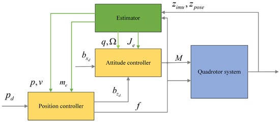
Figure 2.
The structure of the control system.
4. Simulation and Experiment Results
4.1. Simulation
To evaluate the efficacy of the proposed EKF estimation algorithm and the new control structure, numerical simulations are conducted. The dynamic model used in the simulation adopts the form presented in Section 2, with white noise added to simulate real-world scenarios. The primary parameters of the quadrotor UAV are outlined in Table 1.

Table 1.
Parameters of the quadrotor UAV.
The initial state of the quadrotor UAV was set to
The mass and inertial matrix of the quadrotor UAV utilized in the estimator were initialized at
The coefficients of the controller were set to
The measurement sources were selected as the pose sensor and IMU. According to the observability analysis in Section 2, all variables in the extended state vector are observable. The quadrotor UAV was commanded to track a circular trajectory:
The measurement frequency for both the IMU and the pose sensor is 100 Hz. To address inconsistencies in the sampling times, interpolation methods are employed to align the timestamps. Figure 3 illustrates the estimated parameters of the quadrotor UAV throughout the simulation. It can be noted that the initial values for mass and inertial matrix in the estimator differ significantly from the actual values, with an initial error in the mass of and an initial error in the inertial matrix of . The estimated values for mass and inertial matrix converge within one second, with an estimation error of approximately . As the dynamics involving the inertial matrix possess stronger nonlinear characteristics, the estimation is more susceptible to the impact of numerical calculation accuracy. In the initial stages of trajectory tracking, the quadrotor UAV experienced significant changes in position and attitude, and the limited numerical calculation accuracy led to a relatively large error in the estimation of the inertial matrix.
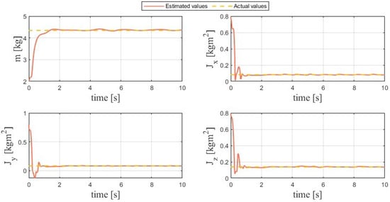
Figure 3.
Inertia parameters’ estimation curves.
For comparison with traditional control structures, we tested the trajectory tracking performance of the proposed robust geometric controller and a traditional geometric controller [8] using the same configuration. The results are shown in Figure 4, where the dashed yellow line represents the desired value, and the solid blue and orange lines illustrate the performance of control structures with and without the estimator, respectively. During the stable phase from 4 s to 10 s, the tracking errors across the three dimensions are for the proposed robust controller and for the geometric controller alone. The root mean squared errors (RMSEs) are 0.033 m and 0.2 m, respectively.
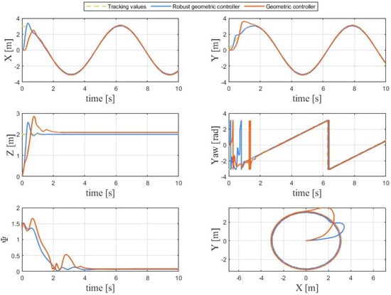
Figure 4.
Comparison of control tracking performance with and without an estimator in the control system.
As can be observed, after the stabilization of parameter estimation, the quadrotor’s tracking precision in all three dimensions generally exceeds that of the control system without an estimator, with improvements of approximately . The comparison of tracking precision along the axis is particularly remarkable. This is because gravity, influenced by the mass parameter, predominantly affects control performance in the vertical direction. The estimator can timely compensate for deviations in mass, thereby enabling the quadrotor UAV to minimally reduce the tracking error along . Additionally, for attitude control precision, the control structure incorporating an estimator significantly outperforms the one without, reducing the average attitude tracking error by 0.069. This indicates that the inertia parameters estimated by the estimator effectively enhance the control performance of the geometric controller. Collectively, these results prove the effectiveness and superiority of the proposed control scheme.
4.2. Experiments
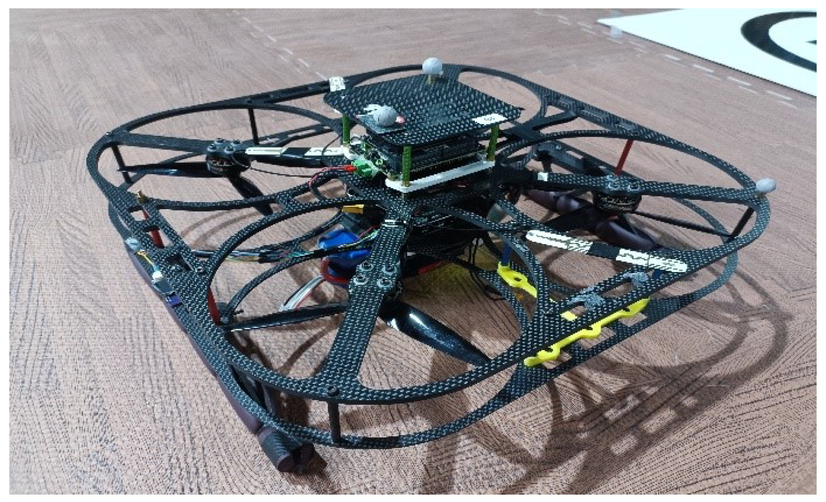
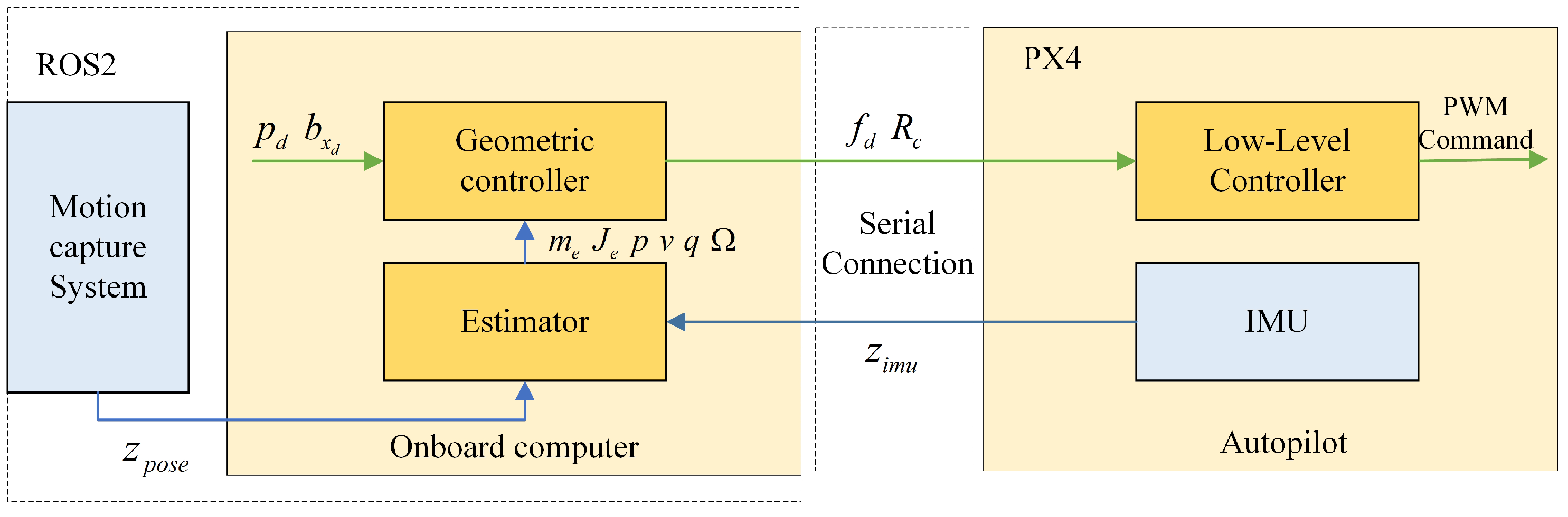
The quadrotor UAV used in experiments, as shown in Figure 5, was designed by us. The system’s architecture is illustrated in Figure 6. The quadrotor UAV is equipped with a Jetson Xavier NX (Nvidia) onboard computer and a CUAV X7 Pro autopilot (CUAV, Guangzhou, China). The geometric controller and EKF-based estimator running on the onboard computer utilize Robot Operating System 2 (ROS2) as the programming framework. The estimator utilizes the measurements from the IMU on the autopilot and the motion capture system to calculate state and parameter estimates, which are then utilized by the geometric controller. The autopilot runs the PX4 flight stack as the low-level controller, converting commands from the geometric controller into PWM signals to actuate the motors. In the quadrotor system, the onboard computer and autopilot are connected via a wired serial connection, and the pose calculated by the motion capture system is sent to the computer via a local area network.

Figure 5.
The quadrotor UAV used in the experiment.
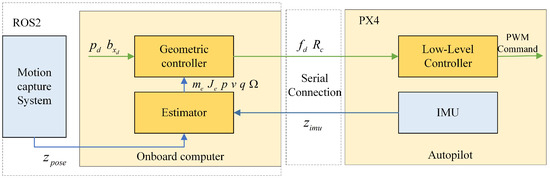
Figure 6.
The structure of the quadrotor UAV system used in experiments.
The parameters of the quadrotor UAV used in the experiments are identical to those in the simulations. The inertia matrix was calculated from the CAD model, while the thrust and torque coefficients were measured using a thrust testbed. In the experiment, the quadrotor UAV was required to follow a circular trajectory similar to the simulation but with a fixed yaw:
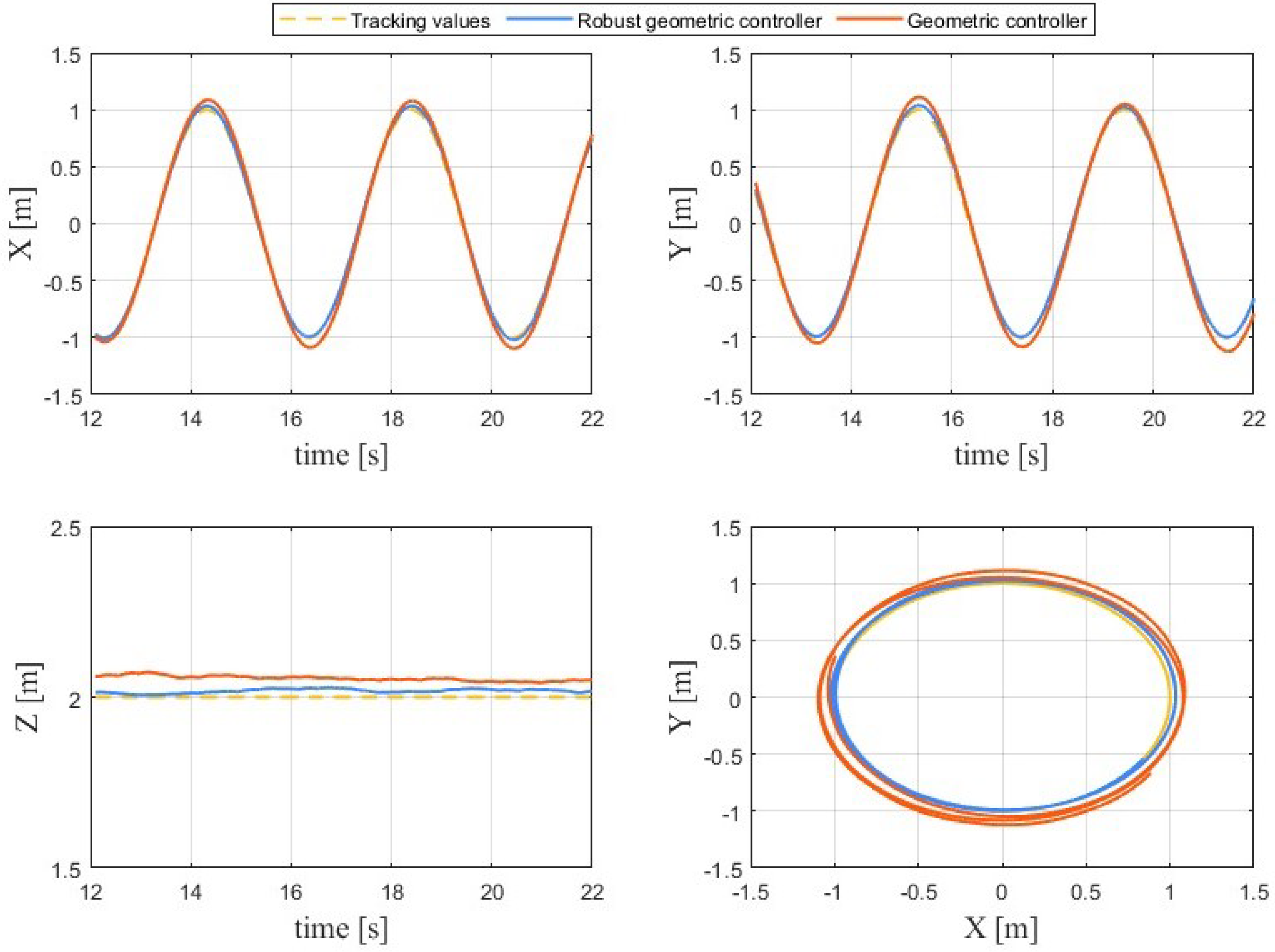
It is important to note that in practice, the observability of the mass and inertia matrix parameters weakens when the system’s thrust and torque inputs are near zero. This can lead to incorrect parameter estimation, potentially causing divergence. To address this, this phenomenon was monitored by examining the covariance of the estimated parameters. Stable control performance was ensured by setting reasonable boundaries for the estimates and promptly resetting them to the last stable estimated values whenever a divergence occurred. The experimental results are shown in Figure 7. The tracking errors across the three dimensions during the stable phase are for the proposed robust controller and for the geometric controller alone. Furthermore, the RMSE values are 0.020 m and 0.061 m, respectively.
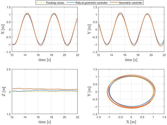
Figure 7.
Comparison of trajectory tracking effects.
From the comparison of experimental results, it is evident that the proposed control structure, with the estimator’s compensation for parameters, achieved improved trajectory tracking accuracy. The enhancements in tracking precision across the three dimensions were . This further demonstrates its advantages in practice.
5. Conclusions
In conclusion, this paper introduces a robust geometric controller for a quadrotor UAV, formulated directly on the nonlinear SE(3) configuration manifold. To enhance its robustness against system uncertainties, an EKF-based parameter estimator was designed to estimate the inertia parameters of the quadrotor UAV, including mass and the inertial matrix. By integrating this estimator into the geometric controller loop, the entire control system was able to effectively identify uncertainties in the quadrotor UAV system, efficiently compensating for the effects of parameter perturbations. In the design of the estimator, quaternions were used to represent attitude and to avoid the singularities caused by Euler angles and the computational complexity brought by rotation matrices without affecting the control performance. The Lyapunov stability of the entire system is demonstrated, showing that the system remains stable during the convergence of estimation errors and exhibits exponential stability after the errors converge to zero.
To demonstrate the efficacy of the proposed method, a series of simulations and experiments were performed on a quadrotor UAV. The results demonstrated that the proposed controller performs much better than conventional geometric controllers, thereby underscoring its efficacy in advancing quadrotor control for real-world applications.
Author Contributions
Conceptualization, B.L. (Bo Lei) and B.L. (Bo Liu); methodology, B.L. (Bo Lei) and B.L. (Bo Liu); software, B.L. (Bo Lei) and B.L. (Bo Liu); validation, B.L. (Bo Lei) and B.L. (Bo Liu); formal analysis, B.L. (Bo Lei); investigation, B.L. (Bo Lei); resources, B.L. (Bo Liu); data curation, B.L. (Bo Liu); writing—original draft preparation, B.L. (Bo Lei) and B.L. (Bo Liu); writing—review and editing, B.L. (Bo Lei) and B.L. (Bo Liu); visualization, B.L. (Bo Lei); supervision, C.W.; project administration, C.W.; funding acquisition, C.W. All authors have read and agreed to the published version of the manuscript.
Funding
This research was funded by the Touyan Innovation Program of Heilongjiang Province, China.
Data Availability Statement
Data are contained within the article.
Conflicts of Interest
The authors declare no conflicts of interest.
References
- Naidoo, Y.; Stopforth, R.; Bright, G. Development of an UAV for Search & Rescue Applications Mechatronic Integration for a Quadrotor Helicopter. In Proceedings of the IEEE AFRICON, Victoria Falls, Zambia, 13–15 September 2011. [Google Scholar]
- Chen, T.; Shan, J. A Novel Cable-Suspended Quadrotor Transportation System: From Theory to Experiment. Aerosp. Sci. Technol. 2020, 104, 105974. [Google Scholar] [CrossRef]
- Elmokadem, T. Distributed Coverage Control of Quadrotor Multi-UAV Systems for Precision Agriculture. IFAC Pap. Online 2019, 52, 51–256. [Google Scholar] [CrossRef]
- Pounds, P.E.I.; Bersak, D.R.; Dollar, A.M. Stability of Small-Scale UAV Helicopters and Quadrotors with Added Payload Mass under PID Control. Auton. Robot. 2012, 33, 129–142. [Google Scholar] [CrossRef]
- Hanif, A.; Putro, I.E.; Riyadl, A.; Sudiana, O.; Irwanto, H.Y. Towards High-Precision Quadrotor Trajectory Following Capabilities: Modelling, Parameter Estimation, and LQR Control. Latv. J. Phys. Tech. Sci. 2024, 61, 89–104. [Google Scholar] [CrossRef]
- Elena Antonio-Toledo, M.; Sanchez, E.N.; Alanis, A.Y.; Florez, J.A.; Perez-Cisneros, M.A. Real-Time Integral Backstepping with Sliding Mode Control for a Quadrotor UAV. IFAC Pap. Online 2018, 51, 549–554. [Google Scholar] [CrossRef]
- Dong, W.; Gu, G.Y.; Zhu, X.; Ding, H. High-Performance Trajectory Tracking Control of a Quadrotor with Disturbance Observer. Sens. Actuators Phys. 2014, 211, 67–77. [Google Scholar] [CrossRef]
- Lee, T.; Leok, M.; McClamroch, N.H. Geometric Tracking Control of a Quadrotor UAV on SE(3). In Proceedings of the 49th IEEE Conference on Decision and Control (CDC), Atlanta, GA, USA, 15–17 December 2010; pp. 5420–5425. [Google Scholar] [CrossRef]
- Goodarzi, F.A.; Lee, T. Extended Kalman Filter on SE(3) for Geometric Control of a Quadrotor UAV. In Proceedings of the 2016 International Conference on Unmanned Aircraft Systems (ICUAS), Arlington, VA, USA, 7–10 June 2016; pp. 1371–1380. [Google Scholar] [CrossRef]
- Zhang, H.; Zhang, X.; Li, T.; Zhang, S.; Zhang, X. Barrier Function Enhanced Geometric Controller for Safe Control of a Quadrotor UAV. In Proceedings of the 2022 International Conference on Advanced Robotics and Mechatronics (ICARM), Guilin, China, 9–11 July 2022; pp. 187–192. [Google Scholar] [CrossRef]
- Sharma, M.; Kar, I. Finite Time Disturbance Observer Based Geometric Control of Quadrotors. IFAC Pap. Online 2020, 53, 295–300. [Google Scholar] [CrossRef]
- Sharma, M. Geometric Control of Uncertain Quadrotor with External Disturbances. In Proceedings of the 2022 IEEE 19th India Council International Conference (INDICON), Kochi, India, 24–26 November 2022; pp. 1–5. [Google Scholar] [CrossRef]
- Wang, J.; Yuan, X.; Zhu, B. Geometric Control for Trajectory-Tracking of a Quadrotor UAV with Suspended Load. IET Control Theory Appl. 2022, 16, 1271–1281. [Google Scholar] [CrossRef]
- Goodman, J.R.R.; Beckers, T.; Colombo, L.J.J. Geometric Control for Load Transportation With Quadrotor UAVs by Elastic Cables. IEEE Trans. Control Syst. Technol. 2023, 31, 2848–2862. [Google Scholar] [CrossRef]
- Shastry, A.K.; Paley, D.A. System Identification for High-Performance UAV Control in Wind. Int. J. Robust Nonlinear Control 2023, 33, 10451–10467. [Google Scholar] [CrossRef]
- Bansal, S.; Akametalu, A.K.; Jiang, F.J.; Laine, F.; Tomlin, C.J. Learning Quadrotor Dynamics Using Neural Network for Flight Control. In Proceedings of the 2016 IEEE 55th Conference on Decision and Control (CDC), Las Vegas, NV, USA, 12–14 December 2016; pp. 4653–4660. [Google Scholar] [CrossRef]
- Bauersfeld, L.; Kaufmann, E.; Foehn, P.; Sun, S.; Scaramuzza, D. NeuroBEM: Hybrid Aerodynamic Quadrotor Model. In Proceedings of the Robotics: Science and Systems XVII, Robotics: Science and Systems Foundation, Virtual, 12–16 July 2021. [Google Scholar] [CrossRef]
- Kwon, G.; Lee, J.; Yang, H. Real-Time Observability-Aware Inertia Parameter Estimation for Quadrotors. IEEE Access 2023, 11, 24299–24314. [Google Scholar] [CrossRef]
- Yu, Y.; Tang, P.; Song, T.; Lin, D. A Two-Step Method for System Identification of Low-Cost Quadrotor. Aerosp. Sci. Technol. 2020, 96, 105551. [Google Scholar] [CrossRef]
- Munguía, R.; Urzua, S.; Grau, A. EKF-Based Parameter Identification of Multi-Rotor Unmanned Aerial Vehicles Models. Sensors 2019, 19, 4174. [Google Scholar] [CrossRef] [PubMed]
- Böhm, C.; Scheiber, M.; Weiss, S. Filter-Based Online System-Parameter Estimation for Multicopter UAVs. In Proceedings of the Robotics: Science and Systems XVII. Robotics: Science and Systems Foundation, Virtual, 12–16 July 2021. [Google Scholar] [CrossRef]
- Wüest, V.; Kumar, V.; Loianno, G. Online Estimation of Geometric and Inertia Parameters for Multirotor Aerial Vehicles. In Proceedings of the 2019 International Conference on Robotics and Automation (ICRA), Montreal, QC, Canada, 20–24 May 2019; pp. 1884–1890. [Google Scholar] [CrossRef]
- Bianchi, D.; Di Gennaro, S.; Di Ferdinando, M.; Acosta Lua, C. Robust Control of UAV with Disturbances and Uncertainty Estimation. Machines 2023, 11, 352. [Google Scholar] [CrossRef]
- Svacha, J.; Paulos, J.; Loianno, G.; Kumar, V. IMU-Based Inertia Estimation for a Quadrotor Using Newton-Euler Dynamics. IEEE Robot. Autom. Lett. 2020, 5, 3861–3867. [Google Scholar] [CrossRef]
- Leshikar, C.; Eves, K.; Ninan, N.; Valasek, J. Asymmetric Quadrotor Modeling and State-Space System Identification. In Proceedings of the 2021 International Conference on Unmanned Aircraft Systems (ICUAS), Athens, Greece, 15–18 June 2021; pp. 1422–1431. [Google Scholar] [CrossRef]
- Cortés-Benito, I.; Tlatelpa-Osorio, Y.E.; Martínez-Ramírez, M.; Romero, J.G.; Rodríguez-Cortés, H. Experimental Quadrotor Physical Parameters Estimation. In Proceedings of the 2023 International Conference on Unmanned Aircraft Systems (ICUAS), Warsaw, Poland, 6–9 June 2023; pp. 1356–1362. [Google Scholar] [CrossRef]
- Jeon, H.; Min, J.; Bang, H.; Youn, W. Quaternion-Based Iterative Extended Kalman Filter for Sensor Fusion of Vision Sensor and IMU in 6-DOF Displacement Monitoring. IEEE Sens. J. 2022, 22, 23188–23199. [Google Scholar] [CrossRef]


Disclaimer/Publisher’s Note: The statements, opinions and data contained in all publications are solely those of the individual author(s) and contributor(s) and not of MDPI and/or the editor(s). MDPI and/or the editor(s) disclaim responsibility for any injury to people or property resulting from any ideas, methods, instructions or products referred to in the content. |
© 2024 by the authors. Licensee MDPI, Basel, Switzerland. This article is an open access article distributed under the terms and conditions of the Creative Commons Attribution (CC BY) license (https://creativecommons.org/licenses/by/4.0/).