Article

Design and Self-Calibration Method of a Rope-Driven Cleaning Robot for Complex Glass Curtain Walls

1
School of Mechanical Engineering, Hebei University of Technology, Tianjin 300130, China
2
School of Optics and Photonics, Beijing Institute of Technology, Beijing 100081, China
3
State Key Laboratory of Reliability and Intelligence of Electrical Equipment, Hebei University of Technology, Tianjin 300130, China
4
School of Electrical Engineering, Hebei University of Technology, Tianjin 300130, China
*
Authors to whom correspondence should be addressed.
Actuators 2024, 13(7), 272; https://doi.org/10.3390/act13070272
Submission received: 18 June 2024 / Revised: 17 July 2024 / Accepted: 18 July 2024 / Published: 20 July 2024
(This article belongs to the Section Actuators for Robotics)

Abstract

:
Rope-driven robots are increasingly used to safely and efficiently clean complex glass curtain walls. However, continuous global cleaning is difficult for most robots because of their poor performance in overcoming obstacles and adapting to curved surfaces, and an inconvenient winch calibration on complex surfaces further burdens such work. This paper presents a 3-DOF rope-driven robot and a winch self-calibration method for efficient cleaning. The robot, by integrating a 5-rope parallel configuration, a self-adaptive cleaning body, and a self-compensating driving winch, is designed to perform continuous, compliant, and accurate spatial motion on curved walls with obstacles. By deducing the kinematic model, the constraint relationship related to orderly arranged winch positions, maneuverable body positions, and accessible rope lengths is established during the robot tracking 3D trajectory. Combining the established relationship, a series of regulations are formulated for easily acquiring body positions and rope lengths, and then a self-calibration method is proposed by accurately calculating winch positions without using professional instruments. Experimental results show that the robot can perform global and precise movement on complex glass surfaces. Applying the proposed method, the maximum winch calibration error is 6.6 mm, and the maximum body tracking error is controlled within 9.6 mm.

1. Introduction

With advancements in construction technology, the number of glass curtain walls used in high-rise buildings world-wide has increased due to their high transparency and lighter weight. Unfortunately, the glass wall needs to be regularly maintained by cleaning their appearance to prolong the building service time [1,2]. The diversified glass-facade shapes in construction have forced humans to use robots to avoid inefficient, costly, and dangerous operations. Currently, two main driving ways are applied to glass-facade-cleaning robots: body-driven [3,4,5,6] and rope-driven [7,8,9,10]. Body-driven robots generally use vacuum technology to adhere to vertical glass independently [11,12,13]; however, the adsorption capacity is greatly affected by the flatness and roughness of the wall surface. While rope-driven robots are generally driven by winches fixed on the roof, and most of the weight is carried on the ropes rather than glass [14]. Therefore, they can be applied to rough wall surfaces and reduce requirements for wall flatness. By comparison, rope-driven robots are relatively more reliable for cleaning most glass walls. However, modern glass facades may be randomly distributed with functional devices which hinder robot movement, resulting in the inability to clean the whole wall. In addition, due to the complex glass shape, using measuring instruments to calibrate winch positions may be limited because measuring path being blocked is likely to cause instrument failure.
Extensive studies have been conducted for rope-driven robots, focusing on the current technological gaps, mainly on obstacle-overcoming mechanisms, motion control manners, and winch calibration methods. Robots with various driving mechanisms have been studied to meet the requirement of continuous motion on all types of wall surfaces. For example, TITO [15], driven by a winch installed on a railroad fixed to a roof, can move vertically and horizontally through ropes pulling and a winch moving along the railroad, respectively. It can only perform cleaning tasks on flat surfaces; however, continuous operation on raised walls is still difficult. To enhance the obstacle-overcoming ability, Dai et al. [16] added an electric push rod that can extend perpendicular to the wall to push ropes away from the surface, so the robot can overcome obstacles, but its performance is restricted by the rod length. ROPE RIDE, proposed by Seo et al. [17], comprises four triangular tracks on the cleaning body as a crawling mechanism. When the body ascends, the triangular tracks passively rotate to overcome obstacles. However, the height of the obstacle that the robot can overcome is still quite limited, and this capability only works in the vertical direction.
To realize the stable motion of robots on complex surfaces, scholars proposed a series of motion control methods using various winch installation configurations [18,19,20,21]. Existing winch configurations of rope-driven robots generally take two forms: removable winch [17] and fixed winch [22,23,24,25]. The removable winch form usually installs a railroad or gantry on the roof. For horizontal and vertical movements, the rope elongation and the distance of the winch movement along the railroad are adjusted, respectively. For instance, TITO [15] and SIRIUSc [26] can reach any position on the plane by combining the transverse driving of railroad and vertical driving of ropes. However, because of unpredictable winds, the body becomes unstable when moving horizontally. The fixed winch form generally installs winches in the different corners of a building [27,28]. This form adjusts the body position by coordinating the elongation of each rope. For example, Yoo et al. [29] developed a 2-DOF parallel robot system that installs two ropes on the roof. This robot can realize a 2-DOF motion on the wall by adjusting the length of two ropes in combination with gravity. Manipulation is simple; however, the motion stability in operation should be improved. Kite [30] uses four independent winches to control four ropes from different angles, respectively. Thus, a planar 2-DOF redundant parallel mechanism is formed by winches and the body, thereby effectively ensuring the movement stability of the robot.
Based on the above studies, winch position calibration is the precondition of effective body movement for rope-driven robots. Thus, various calibration methods have been studied [31,32,33]. Typical rope-driven cleaning robots, such as TITO and Kite, need to directly measure winch positions using professional instruments. However, owing to the complex and diverse roof types, direct measurement becomes difficult, resulting in inefficient work [34]. Therefore, others proposed a convenient calibration method for rope suspension points of the robot with winch integrated into the moving body. Before the operation, the robot moves autonomously according to the preconcerted trajectory. After reaching the expected anchor points, the end hook of each rope is, respectively, hung from the suspension points on the surface. Thus, the positions of suspension points can be calibrated by body positioning. Wang et al. [35] adopted this method in solar panel cleaning and realized efficient calibration, verifying that the self-calibration theory can greatly reduce workload. However, applying this method directly to complex facades is difficult because of the inadequate wall-climbing performance of this robot.
In summary, aiming at the cleaning requirement of complex glass curtain walls, existing rope-driven robots should mainly be improved in the following three aspects. (1) Robots can perform well on flat or slightly raised walls based on a typical planar parallel configuration. However, theoretically, the cleaning body cannot reach far outside the wall surface. Therefore, satisfying the requirements of flexibly overcoming obstacles and a continuous global operation on complex walls is difficult. (2) Robots with fixed and redundant winches can be controlled to move stably in a plane using a planar kinematic model. However, global operation on complex walls requires 3D path planning due to their irregular surfaces. Therefore, a 3D kinematic model is required to realize the subsequent spatial trajectory. (3) Most existing robots solve the winch calibration problem on flat walls by direct measurement or autonomous robot tracking location. But the increasing complexity of walls makes instrument measuring inconvenient and increases the difficulty of robot motion, resulting in low positioning efficiency. Therefore, realizing the convenient calibration of winch positions on complex walls is a key research topic.
To solve these problems, we present a 3-DOF rope-driven cleaning robot and a winch self-calibration method. The robot integrates 5-rope parallel configuration, a self-adaptive cleaning body, and self-compensating driving winches to perform continuous, compliant, and accurate spatial motion on curved walls with obstacles. By deducing a 3D kinematic model, the spatial motion can be realized for global operation, and the constraint relationship related to orderly arranged winch positions, maneuverable body positions, and accessible rope lengths is established. Combining the established relationship and easily measured parameters, a self-calibration method for winches is proposed. Through establishing a series of parameter acquisition regulations to combine body positions and rope lengths, winch positions can be accurately calculated to complete calibration without using professional instruments. To verify the performances of the robot and calibration method, we built an experimental platform and conducted a series of experiments.
The rest of this paper is arranged as follows. Section 2 introduces the mechanical design of the cleaning robot. In Section 3, a 3D kinematic model is deduced. Section 4 presents a self-calibration method for the winch position. The experimental result is analyzed in Section 5. Section 6 discusses the advantages and disadvantages of the robot. Finally, conclusions are drawn in Section 7.

2. Structural Design of the Cleaning Robot
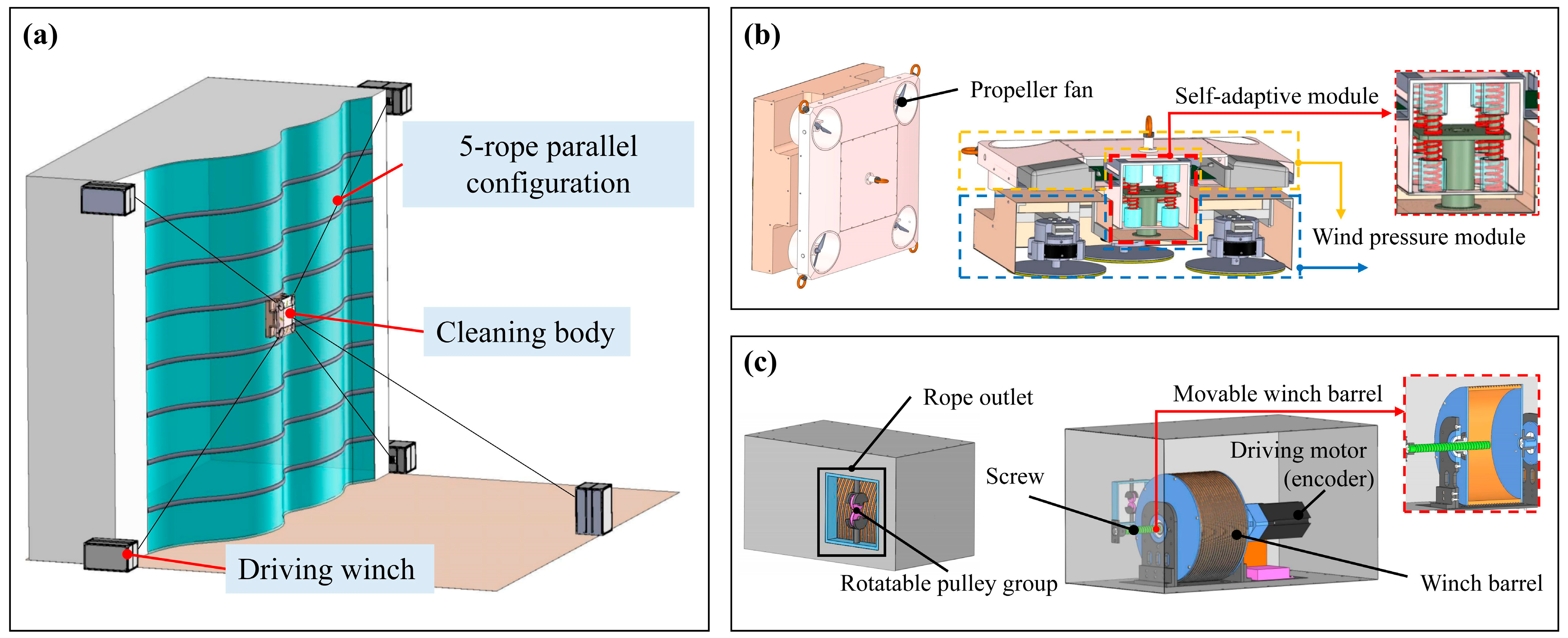
2.1. System Overall

To satisfy the cleaning requirements of complex glass curtain walls, a rope-driven cleaning robot is proposed, which is mainly composed of a cleaning body and driving winches. Since the walls contain randomly distributed obstacles and curved surfaces, continuously operating over a whole wall area for robots is difficult. Moreover, poor fitting to walls and rope length errors will also weaken the cleaning effect and work efficiency. Thus, the 5-rope parallel configuration, self-adaptive cleaning body, and self-compensating driving winch are designed to make the robot acquire continuous, compliant, and accurate spatial motion performance on complex walls for efficient cleaning. The overall structure of the robot is shown in Figure 1.

2.1.1. 5-Rope Parallel Configuration

For rope-driven parallel robots, their degrees of freedom (DOFs) are generally determined by the number and configuration of ropes. Most existing rope-driven cleaning robots are arranged with multiple winches on the wall surface, only allowing for 2D movement along two orthogonal directions in the vertical plane. Thus, they are difficult to reach far outside the wall surface for overcoming obstacles.
For complex wall surfaces with obstacles, robots are required to move perpendicular to the wall to safely traverse, requiring additional DOFs. Therefore, a 5-rope parallel configuration arranged in a non-coplanar manner is proposed for 3D movement, as shown in Figure 1a. Specifically, four winches are installed at the four corners of the wall for stable traversal performance, and an additional winch is installed on the ground to provide normal tension. Thus, five ropes enable the robot to have five controlled motions, which is more than the minimum number of DOFs required for a 3D position and is therefore redundant. By coordinating five winches, the robot can achieve stable movement in 3D space and overcome obstacles, which facilitates a continuous operation of complex walls.

2.1.2. Self-Adaptive Cleaning Body

The self-adaptive cleaning body, the performer of the cleaning operation, contains a cleaning module, a wind pressure module, and a self-adaptive module, as shown in Figure 1b. The cleaning module is equipped with cleaning tools such as brushes and water tanks to directly make contact with and wipe glass walls. The wind pressure module with four propeller fans is used to press the cleaning module on the walls, solving the problem of efficiently cleaning concave surfaces. The self-adaptive module uses four pairs of mutually exclusive springs connected by a movable middle partition to provide a flexible link between the cleaning module and wind pressure module by coordinating spring deformation. Thus, the robot can achieve flexible contact and passive rotation following the curvature change of the surface with wind pressure acting, guaranteeing a tight fit to the wall surface as well as a good cleaning performance.

2.1.3. Self-Compensating Driving Winch

The driving winch is the power unit that drives the cleaning body to move by controlling the winding/unwinding of rope fastened to the body, as shown in Figure 1c. In the rope unwinding process, the rope separation point on the barrel will constantly move away from the rope outlet on the winch box. Therefore, a section of rope is left rather than released outside the box as initially expected, resulting in driving errors. Thus, the driving winch adopts a movable barrel based on a combined motor-and-screw driving method. Due to the equal external thread pitch of the barrel and screw, their opposing movements are offset, so the rope end is constantly perpendicular to the rope outlet, automatically eliminating driving errors. In addition, the rotatable pulley group is designed to follow real-time changes of rope direction as the body moves, effectively reducing the friction between the rope and rope outlet.

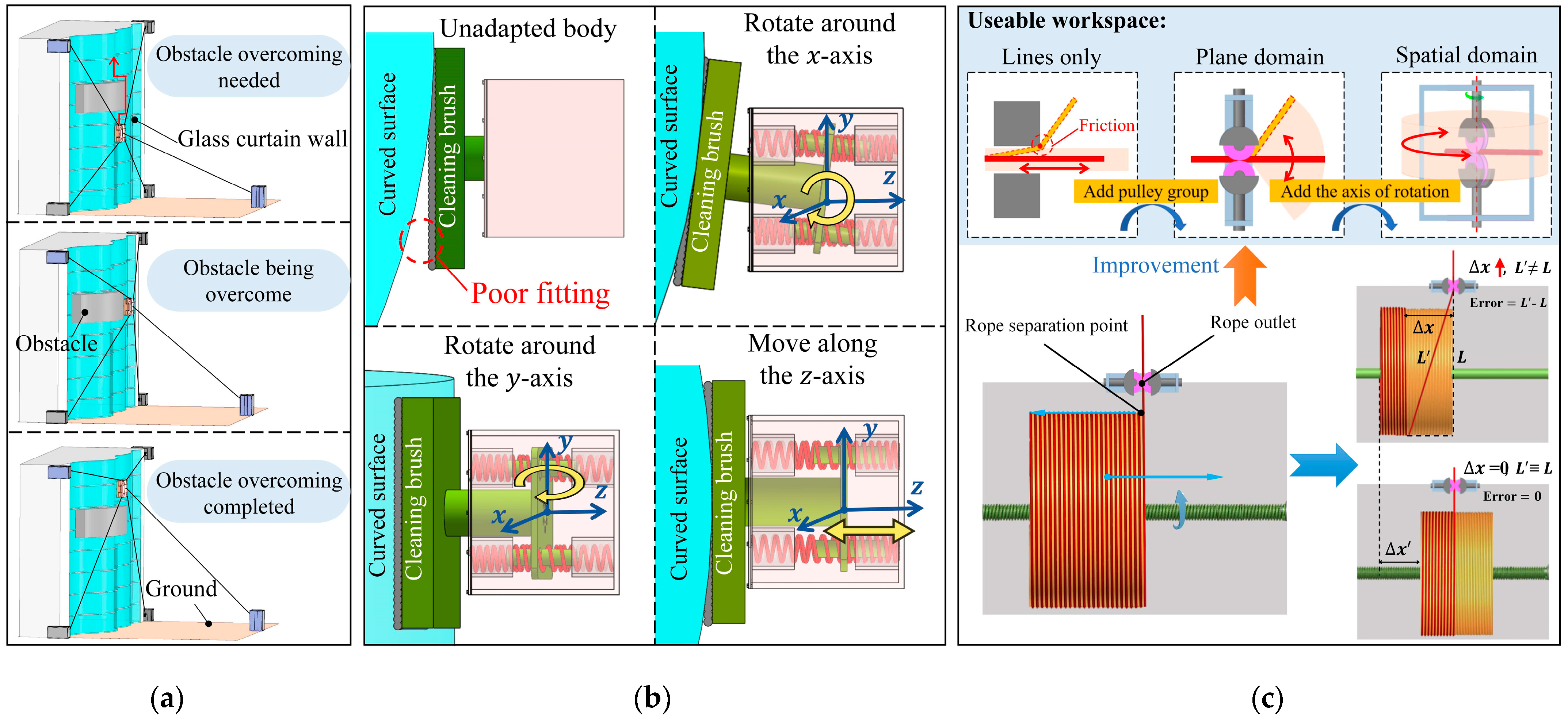
2.2. Working Principle
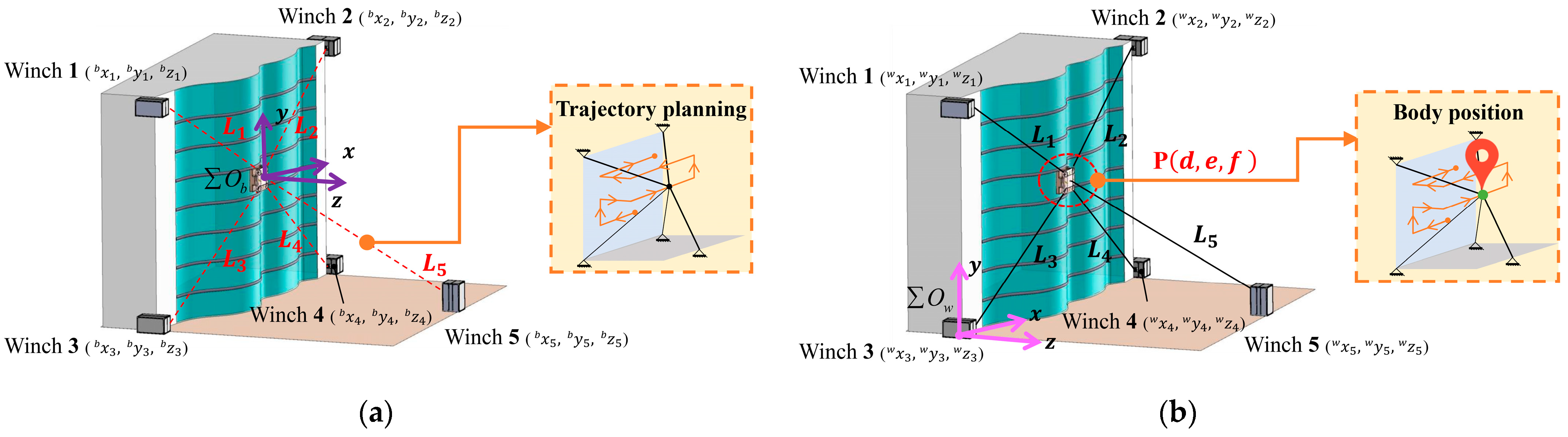
Adopting the 5-rope parallel configuration provides the robot with 3D motion ability to overcome obstacles. Based on a previous study [29], the rope-driven robots connected to more than n + 1 ropes in a space with n degrees of freedom are called redundant rope-driven parallel robots. In such a configuration, ropes in different directions are always subjected to high tension in the workspace, which significantly reduces vibrations in the ropes. Thus, to achieve stable spatial motion, we select five ropes to form a parallel configuration, including four hung on the wall as a redundant layout and one fixed on the ground to drive the body away from the wall. The winches on the wall control four ropes connected to the four corners of the body to provide a uniformly distributed pull force, enabling the body to realize stable planar motion. The winch on the ground controls an additional rope attached to the body’s center to offer a pull force perpendicular to the wall, allowing the robot to achieve 3D motion. In summary, the 5-rope parallel configuration enables the robot to achieve stable spatial motion and overcome obstacles, as shown in Figure 2a.
The self-adaptive cleaning body allows the wiping brushes to passively rotate around multiple axes, ensuring a complete fit to the curved surface, thereby improving the cleaning effect. The body consists of the cleaning module, wind pressure module, and self-adaptive module. The cleaning module is equipped with rotating brushes to wipe glass. The wind pressure module is fitted with four propeller fans at the four corners to form an even stable pressure, pushing the body to closely fit the surface. The self-adaptive module comprises four spring pairs, a movable middle partition, and a shell. Each spring pair, consisting of two springs against each other, is symmetrically installed on both sides of the movable middle partition for flexible contact and rotation. To prevent decentration, guide columns (connected with the partition) are coaxially surrounded by springs and guide grooves (connected with the shell). As the whole body approaches the wall, four spring pairs deform at different degrees under the combined action of wind pressure and wall support force, which makes the cleaning module rotate according to the surface curvature. When the surface obliques along the y-axis, the four springs in the front/back of the middle partition produce different deformations (stretching or compression), which makes the movable middle partition rotate around the x-axis to adapt to the surface; the adaptative rotation around the y-axis is similar. When the body operates on a raised surface, the four springs in the front/back of the middle partition deform equally, which makes the movable middle partition shift along the z-axis, achieving flexible contact and completely fitting to the surface. Hence, under wind pressure, the cleaning body can realize passively flexible self-adaption to curved surfaces from all directions, as shown in Figure 2b.
The self-compensating driving winch is used to decrease rope length errors and improve the body’s movement accuracy for operation efficiency and safety. For traditional winches, in the rope unwinding process, the distance between the rope outlet and rope separation point is expanded when the coil number around the barrel is decreased, and the rope gradually becomes oblique ( L L ), resulting in rope length errors. The more the rope unwinds, the more errors accumulate. Therefore, if the rope separation position is fixed, the rope length errors can be compensated. Inspired by this, a self-compensating winch is designed using a movable barrel. Because the barrel can shift along the screw thread while rotating as the motor works and the rope winds/unwinds according to the external thread on the barrel surface, whose pitch is equal to the screw, the movement distances of the rope separation point and barrel, defined as Δ x and Δ x , respectively, are the same (i.e., Δ x = Δ x ). Furthermore, they move in opposite directions, so the rope separation point will always be perpendicular to the rope outlet, making Δ x = 0 and eliminating the relative distance between the rope separation point and rope outlet caused by rope unwinding. In addition, the conventional rope outlet will rub against the rope as the rope direction is deflected due to body movement, affecting safety and limiting rope useable workspace. Therefore, a rotatable pulley group is designed. The pulley group consists of double pulleys on a tangent along the outer edge of each other to ensure that the rope can be transmitted through the gap. The addition of the rotation axis ensures that the pulley direction always follows the rope departure direction. In summary, the self-compensating driving winch can compensate the movement of the rope separation point to decrease the rope length errors for precise movement and to reduce friction to improve operation safety, as shown in Figure 2c.

3. Kinematic Model

To meet the requirements of global cleaning on complex walls, the robot needs to have stable 3D motion ability, so a spatial 5-rope redundant parallel configuration is adopted. However, it makes a traditional plane kinematic model impracticable. Therefore, a spatial kinematic model is established to calculate rope lengths and body positions for robot 3D motion control, achieving continuous motion on the whole wall.

3.1. Rope Length Solution

To make the robot move according to a planned trajectory required by the cleaning task, the length of each rope needs to be constantly adjusted to make the cleaning body reach the expected position in an orderly manner. In other words, to solve the robot motion control problem, the problem of the lengths of release-needed ropes corresponding to each point on the body trajectory needs to be solved.
For rope-driven parallel configuration, once the coordinates of each winch and the body in a particular position are known, the length of each rope at this time can be figured out. Thus, to determine the rope lengths, a kinematic model based on known winch and body positions is established, as shown in Figure 3a.
To facilitate the calculation, define the origin of the world coordinate system at the position of winch 3, which is the initial robot position. The body’s initial coordinate system O b is defined with the body’s initial position O b as the origin, where x-axis is horizontally forward from winch 1 to winch 2, y-axis in the opposite direction of gravity, and z-axis follows the right-hand helix rule. Since ropes are stretched in straight lines, the distance between the body and each winch is equal to the length of the corresponding rope, when the rope elastic deformation is ignored. Thus, based on winch and body positions, through the distance formula between two points, the issue of rope lengths corresponding to each body position can be solved, as shown in Equation (1):
L i = a x i b 2 + b y i b 2 + c z i b 2
where L i and x i b , y i b , z i b are the rope lengths and winch coordinates in Σ O b corresponding to winch i , respectively, i = 1, 2, 3, 4, 5. ( x , y , z ) is the position coordinates of winches in Σ O b as the body moves ( k m b is the coordinate component along the k-axis of winch m in the Σ O b coordinate system).

3.2. Body Position Solution

Monitoring the trajectory-following effect is essential for robot motion control during operation. Therefore, the body position needs to be acquired in real time.
For a rope-driven parallel redundant configuration, once the winch position coordinates and lengths of part ropes are known, the body position can be solved. To determine body position, a kinematic model based on known winch positions and rope lengths is established, as shown in Figure 3b. Because the spatial position coordinate of the body contains three unknowns, x , y , z , they can be solved simply through randomly selecting three winches from all of them. This study takes winches 1, 2, and 3 as an example.
To facilitate a visual display of the body position, a point O w at winch 3 is taken as the origin to define the work coordinate system O w , where each axis is parallel to the corresponding axis of O b . The initial position of the body is defined as the origin of the work coordinate system O w . According to the geometric relationship between the body and each winch, the equivalent equations between the distance and rope length are listed to solve the body position problem, as shown in Equation (2):
d x 1 w 2 + e y 1 w 2 + f z 1 w 2 = L 1 2 d x 2 w 2 + e y 2 w 2 + f z 2 w 2 = L 2 2 d x 3 w 2 + e y 3 w 2 + f z 3 w 2 = L 3 2
where L i and ( x i w , y i w , z i w ) are the rope lengths and winch coordinates in O w corresponding to winch i , respectively, i = 1, 2, 3. ( d , e , f ) is the position coordinates in O w ( k m w is the coordinate component along the k-axis of winch m in the O w coordinate system).
From the above calculation, Equation (2) has ambiguous solutions in relation to the z-axis, so checking is needed. Thus, winch 5 is selected to list the auxiliary equation for determining the actual body position, as shown in Equation (3):
d x 5 w 2 + e y 5 w 2 + f z 5 w 2 = L 5 2
where L 5 and ( x 5 w , y 5 w , z 5 w ) are the rope length and winch coordinate corresponding to winch 5.
Similarly, selecting other winch groups can also determine the body position.
In summary, by applying the established spatial kinematic model to calculate rope lengths and body position, the robot 3D motion control problem can be solved. Consequently, the robot can effectively follow the expected path on complex walls and clean the whole area with high efficiency.
More importantly, through kinematic analysis, the body position, rope lengths, and winch positions of the rope-driven robot are closely connected, forming a constraint relationship. Thus, as long as two of their parameters are known, the other is determined, which provides a general parameter solution rule for this kind of robot.

4. Self-Calibration of Winch Position Parameters

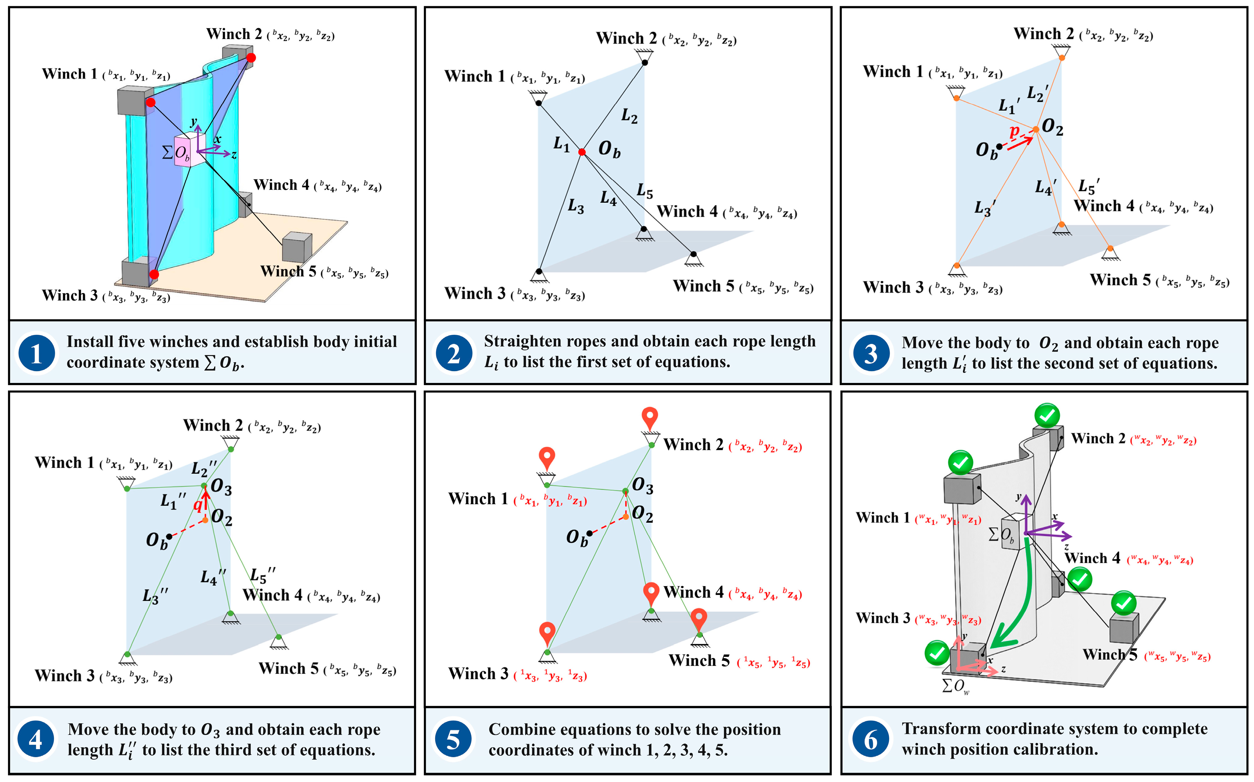
4.1. Self-Calibration Principle

Rope-driven cleaning robots require fixed winches to drive the body when performing tasks. Therefore, the calibration of winch positions is essential. Most existing robots currently rely on professional instruments to directly measure winch positions for achieving calibration. However, the complex shape of walls and harsh on-site environments inevitably increase measurement difficulty and even affect accuracy. Therefore, solving the measuring challenge caused by the instruments with low applicability and robustness, and realizing the convenient calibration of winch position parameters have practical significance.
In essence, winch calibration is to determine robot configuration parameters, namely the relative positions between winches and the body. As previously mentioned, for a rope-driven robot, there is a geometrical constraint relationship among winch positions, rope lengths, and body position. Once two of their parameters are known, the other one can be solved. In fact, directly measuring the winches’ position is difficult because of complex surroundings, whereas the body position and rope lengths are relatively easy to obtain. Therefore, determining winch positions through the analysis and calculation of the easily accessible parameters can avoid direct measurement with the instrument, which provides an idea for the calibration of complex wall winches.
Based on this idea, when the robot configuration is settled, moving the body to some gauge points and monitoring the corresponding rope lengths can generate multiple sets of geometric relationships of robot parameters, which makes winches’ positions solvable by the robot itself. Thus, a series of parameter acquisition regulations are made, as shown in Figure 4. The specific implementation steps are shown below.
(1)
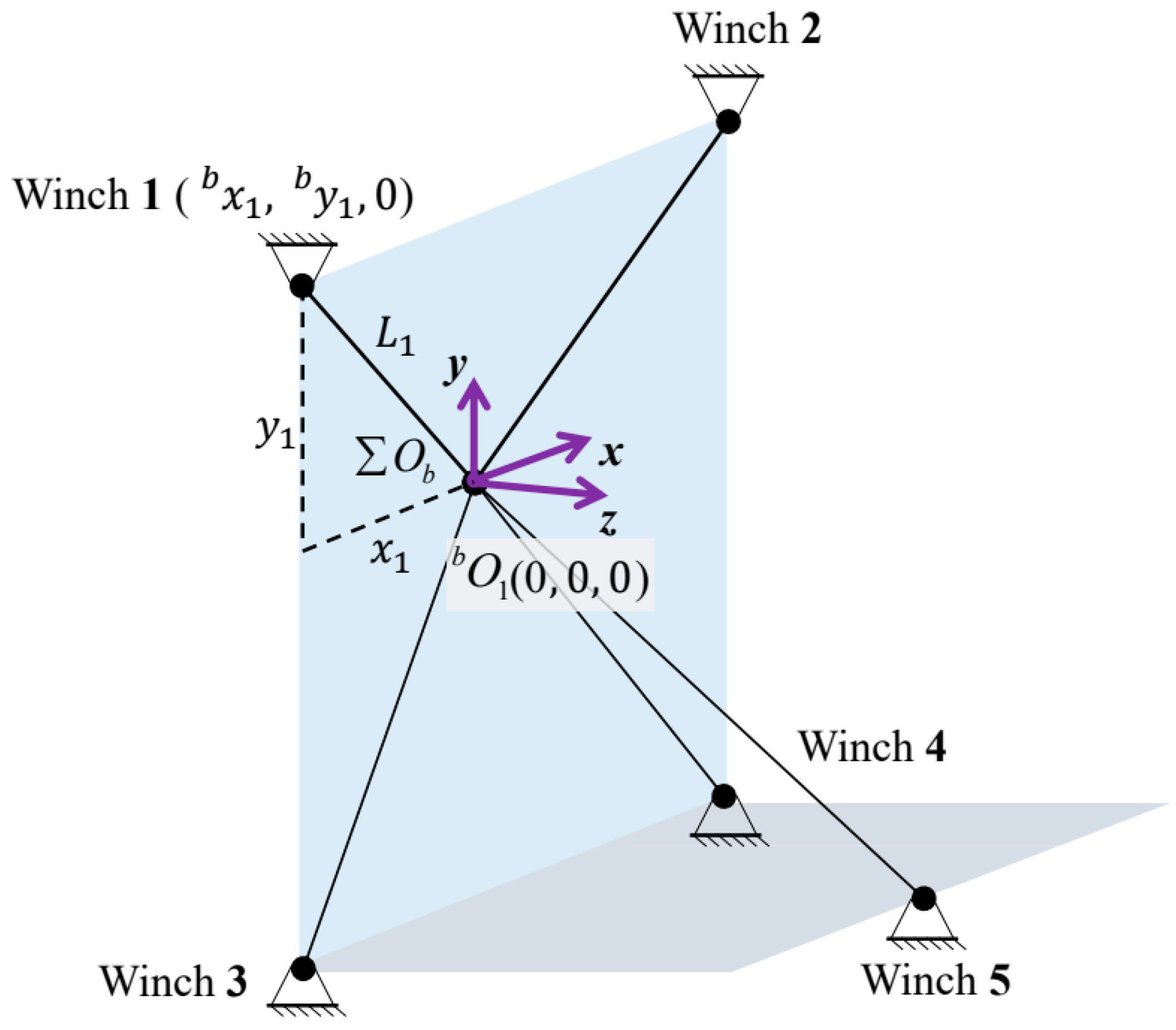
Install four winches at different corners of the wall and the other winch on the ground to settle the robot configuration. Select the plane formed by three points of winches (1, 2, and 3) as the simplified wall, and only straighten the ropes of these three to assign the body’s position, which is placed anywhere on this plane, as the initial position O b (the first gauge point), which is defined as the origin of O b .
(2)
Keep the body at O b , straighten all five ropes, and acquire their rope lengths through encoders. Because the distance between the body and each winch is equal to the corresponding rope length, the first set of distance–rope length equivalent equations can be listed.
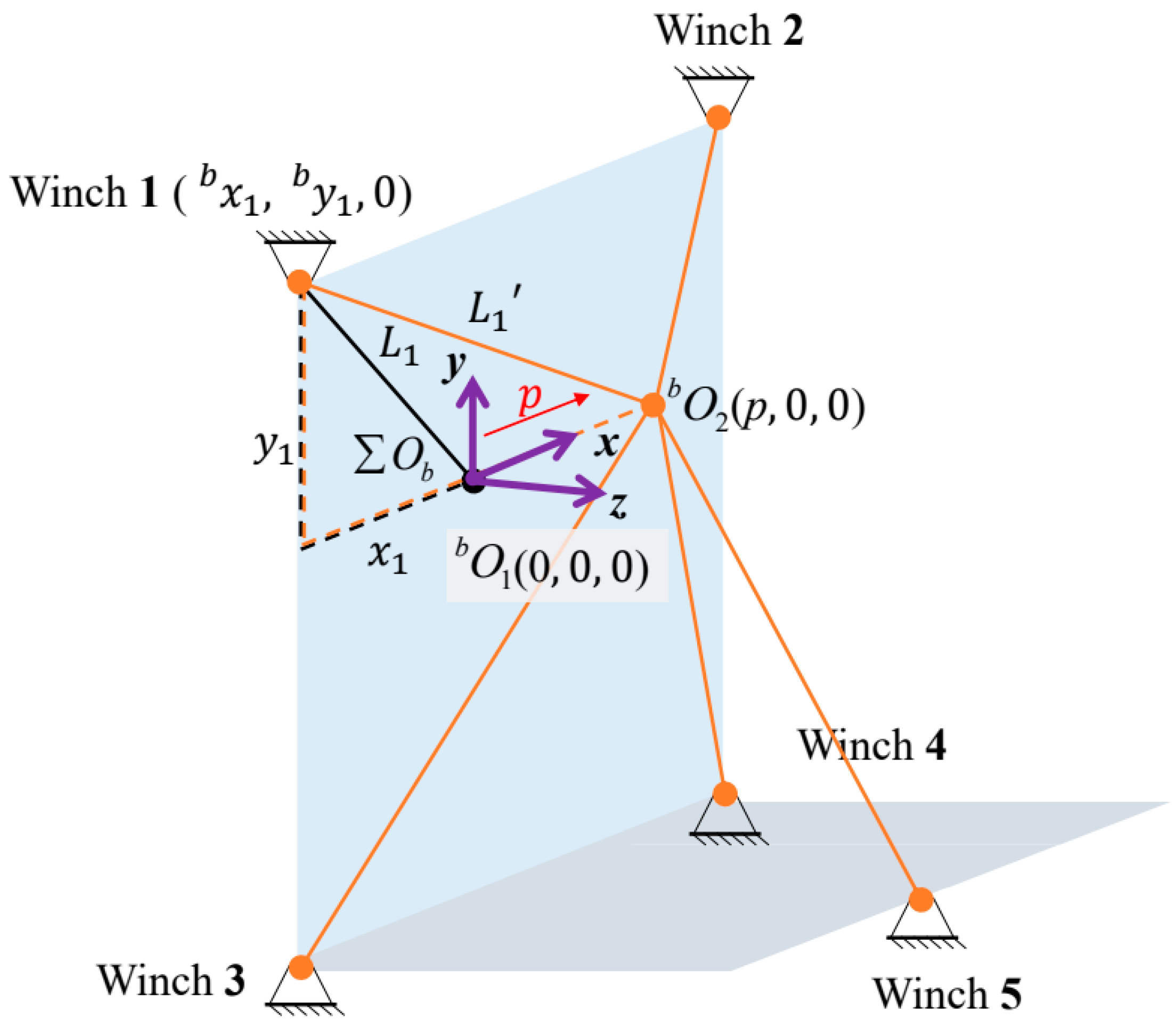
(3)
Coordinately control each rope to move the body along the x-axis direction for p, from O b to O 2 , which is the second gauge point. Similar to step (2), list the second set of equivalent equations.
(4)
From O 2 , coordinately control the ropes again to pull the body vertically upward for q to O 3 , which is the third gauge point. Similar to step (2), list the third set of equivalent equations.
(5)
Combine the above three equation groups from steps (2)–(4), and then the spatial position coordinate of each winch in O b can be solved separately.
(6)
Establish a work coordinate system O w with winch 3 as the origin to visually display the whole working area for subsequent robot trajectory planning. Based on the coordinate of winch 3 in O b , transform the acquired winch coordinates from O b to O w , and the spatial position coordinate of each winch in O w can be solved. The calibration is completed.
Hence, according to the above proposed series of parameter acquisition regulations, winches’ positions can be solved by analyzing and dealing with robot internal geometric constraint relationship formed by rope length and body position data. Thus, by only using the robot parameters themselves, winches can be self-calibrated wherever they were exactly installed. Furthermore, it provides a universal and convenient position calibration method for the rope-driven parallel robots without using professional instruments, which is especially practicable for complex walls.

4.2. Self-Calibration Method

Aiming to realize a convenient calibration of winches on complex walls, a series of parameter acquisition regulations are created. Inspired by the self-calibration principle, a self-calibration method based on the geometric analysis of robot parameters is proposed.
Firstly, install winches according to the designed configuration. To facilitate the solution, we define the coordinate system O b with the initial body position O b as the origin, whose coordinate is defined as gauge point O 1 b ( 0 , 0 , 0 ) in O b . Since three points can form a plane, we assume that the plane formed by winches 1, 2, and 3 is plane x o y in O b . Considering that tensions only exist in the ropes of winches 1, 2, and 3, the body will be placed on the plane x o y . As O b is the supposed origin, the coordinate components along the z-axis of winches 1, 2, and 3 in O b are zero. Thus, the coordinates of winches 1, 2, and 3 are set as ( x i b , y i b , 0 ) ( i = 1 , 2 , 3 ) , respectively, which can be solved just by listing two independent equations according to the equivalence relation between rope length and relative position O b .
Take winch 1 as an example to solve; the solution methods of winches 2 and 3 are similar. As shown in Figure 5, based on the Pythagorean theorem, the first equation can be listed, as shown in Equation (4):
x 1 2 b + y 1 2 b = L 1 2
where x 1 b 2 , y 1 b 2 are the x-axis and y-axis coordinates of winch 1, respectively, and L 1 is the rope length of winch 1 obtained by the encoder.
The second independent equation group cannot be listed if the relative position relationship of the body to winches remains constant. Changing the body’s position can generate new relative relationships. Thus, the second body position O 2 is introduced by moving the body horizontally along the x-axis for p, whose coordinate is defined as gauge point O 2 b ( p , 0 , 0 ) in O b . Based on the geometric relationship shown in Figure 6, the second equation can be listed, as shown in Equation (5).
L 1 2 ( 0 x 1 b ) 2 L 1 ( p x 1 b ) 2 = 0
where L 1 is the rope length of winch 1 obtained by the encoder when the body reaches O 2 , and p is the distance from O b to O 2 .
Therefore, the two unknown coordinates of winch 1 can be solved by combining Equations (4) and (5), and the result is shown in Equation (6):
x 1 b = L 1 2 L 1 2 + p 2 / 2 p y 1 b = L 1 2 x 1 b 2 1 / 2 z 1 b = 0
Equation (6) has multiple solutions on the y-axis, and it can be seen from Figure 6 that y 1 b > 0 , so the negative solution is omitted. The coordinate solution of winch 1 is completed, and winches 2 and 3 are similar.
Moreover, since winches 4 and 5 are outside the plane formed by winches 1, 2, and 3 (plane x o y ), their coordinates have three unknowns ( x i b , y i b , z i b ) ( i = 4 , 5 ) . Thus, solving the coordinates needs three independent equations. Similarly, the third body position O 3 as gauge point O 3 b ( p , q , 0 ) in O b is introduced by moving the body vertically up along y-axis for q.
Take winch 5 as an example to calculate the position coordinate; the solution method of winch 4 is similar. As shown in Figure 7, based on the distance formula between two points in space, the three mutually independent equations can be listed, as shown in Equation (7).
x 5 b 2 + y 5 b 2 + z 5 b 2 = L 5 2 x 5 b p 2 + y 5 b 0 2 + z 5 b 0 2 = L 5 2 x 5 b p 2 + y 5 b q 2 + z 5 b 0 2 = L 5 2
where L 5 , L 5 , and L 5 are the rope lengths of winch 5 obtained by the encoder corresponding to body placed at O 1 , O 2 , and O 3 , respectively; ( x 5 b , y 5 b , z 5 b ) is the coordinate of winch 5, and q is the distance from O 2 to O 3 .
The solutions of Equation (7) are shown in Equation (8):
x 5 b = L 5 2 L 5 2 + p 2 / 2 p y 5 b = L 5 2 L 5 2 + q 2 / 2 q z 5 b = L 5 2 x 5 1 2 y 5 1 2 1 / 2
Equation (8) has multiple solutions on the z-axis, and it can be seen from Figure 7 that z 5 b > 0 , so the negative solution is omitted. The coordinate solution of winch 5 is completed, and winch 4 is similar.
Finally, to visually display the whole working area of the wall, we define the coordinate system O w with the position coordinate of winch 3 as the origin, and transform winch coordinates from O b to O w . Based on the winch 3 coordinate in O b , a transformation relationship between the two coordinate systems can be acquired, as shown in Equation (9):
x i w = x i b x 3 b y i w = y i b y 3 b z i w = z i b z 3 b
where ( x i w , y i w , z i w ) are the corresponding coordinates of winch i in O w , respectively; i = 1, 2, 3, 4, 5. x 3 b , y 3 b , z 3 b is the position coordinate of winch 3 in O b . So far, all the winch coordinates can be solved. Considering the fact that the result expressions are too lengthy and similar, we do not enumerate them.
Consequently, all five winch positions achieved self-calibration just by processing robot geometrical relationships formed by accessible internal parameters. Further, the above calculation process is also practicable if winches are placed at other positions. Hence, the self-calibration method can realize a convenient calibration for randomly placed winches, replacing professional instruments to some extent and solving the challenge of position calibration for rope-driven robots on complex walls.

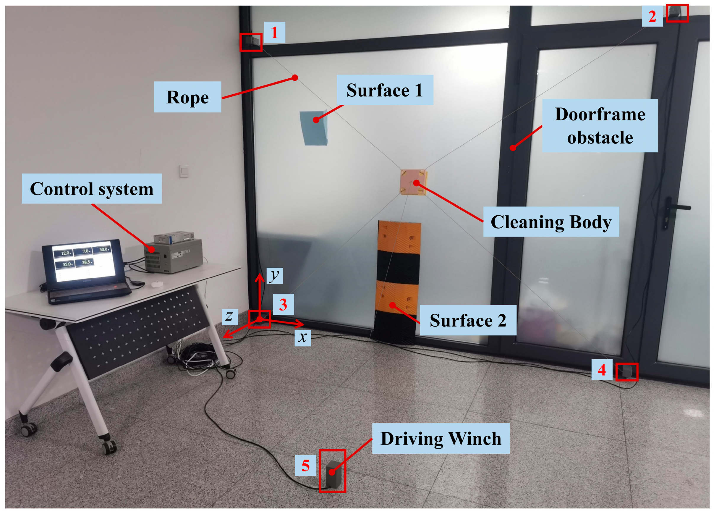
5. Experiment Verification and Analysis

To facilitate a performance validation of the robot and method used, we built an experimental platform. The robot prototype mainly consisted of a self-adaptive cleaning body and five self-compensating driving winches. The glass curtain wall was replaced by an office glass partition, and the obstacle and curved surfaces were simulated by the raised doorframe and 3D-printed curving plates, respectively.
The five driving winches were installed at the experimental site according to the 5-rope parallel configuration to control the body’s motion. As shown in Figure 8, winches 1 and 2 were installed on the wall 2.5 m above the ground, and the distance between them was 3 m. Winches 3 and 4 were installed at the bottom of the wall with a distance of 3 m between them, and winches 1, 2, 3, and 4 formed a rectangle. Winch 5 was installed on the ground, 3 m from the wall. The 3D position coordinates of the geometric center of winches, obstacles, and surfaces are shown in Table 1. To facilitate the analysis, a work coordinate system was set up with winch 3 as the origin, where the x-axis was horizontally forward from winch 3 to winch 4, the y-axis was in the opposite direction of gravity, and the z-axis followed the right-hand helix rule. In addition, a control system was used to regulate each winch winding/unwinding rope and receive rope length data in real time.
To verify the performances of the robot such as overcoming obstacles, curved surface adaptation and trajectory following, and the effectiveness of the self-calibration method, a series of experiments were carried out. We evaluated through the experiments the performance of the robot and the method by comparing the actual trajectory of the body with the expected trajectory under ideal conditions. Through continuous observation using a camera, the accurate actual position of the body at each moment of movement was obtained.

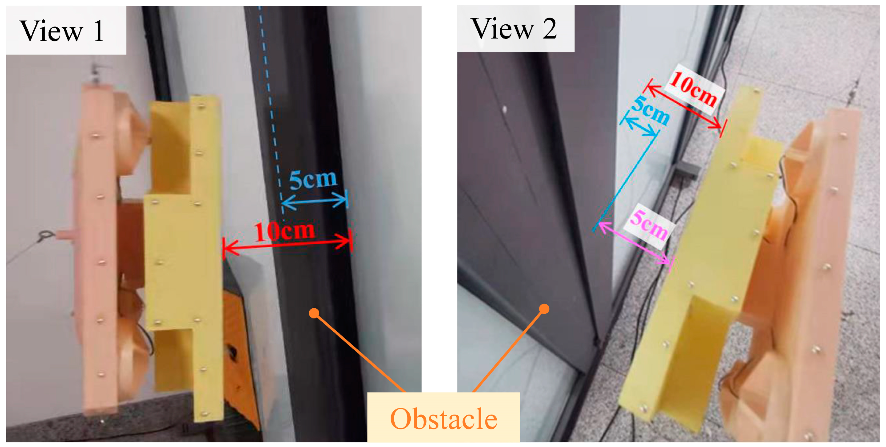
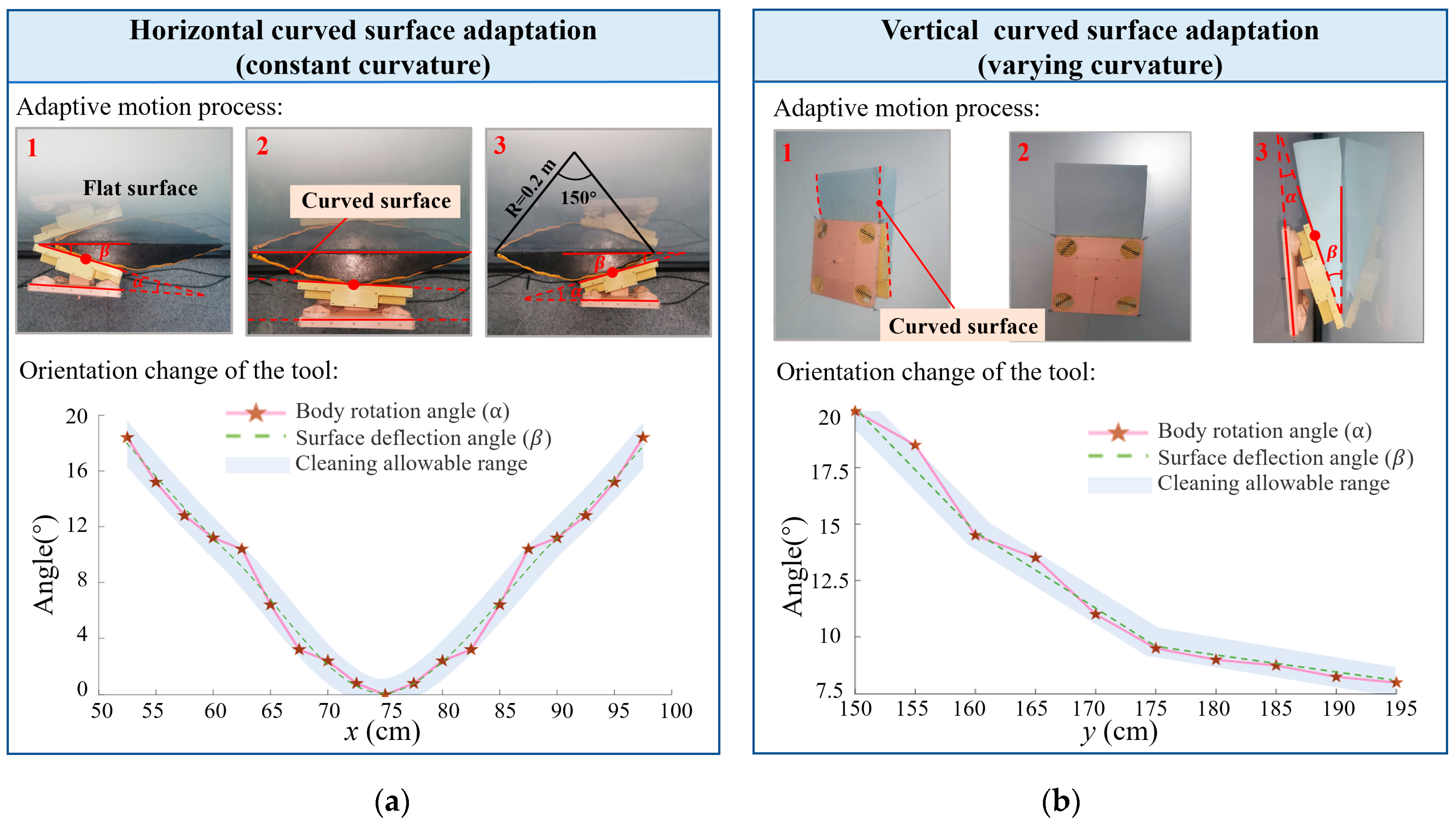
5.1. Overcoming Obstacles and Surface Adaption Experiments

To ensure an efficient operation on curved walls with obstacles, the robot needs to be good at overcoming obstacles and show a good surface adaption performance. Therefore, the 5-rope parallel configuration and self-adaptive cleaning body were designed, and the overcoming obstacle and surface adaption experiments were conducted to verify their performances.
By controlling the winches to pull the body away from the wall surface, we tested its maximum obstacle-overcoming performance. After repeating the tests many times in different positions, it can be seen that the maximum obstacle crossing height of the robot can reach up to about 30 cm at the experiment site. Take a 5 cm high doorframe obstacle as an example to verify the stability and safety during obstacle-crossing, as shown in Figure 9. The results show that the body is kept 10 cm away from the wall surface during overcoming, while the obstacle height is 5 cm, ensuring a sufficient safety margin. According to the above results, the 5-rope parallel configuration allows the robot to have flexible motion capability in 3D space and obstacle-overcoming ability without contact, which meets the global cleaning requirements for complex walls.
To verify the performance of the cleaning body, a surface self-adaption experiment was conducted. When operating on the curved surface, the self-adaptive cleaning body allowed the wiping tools to passively rotate according to the curvature and were guaranteed to fully fit. As shown in Figure 10, the rotation angle of the body and the deflection angle of the curved surface relative to the flat surface are defined as α and β , respectively. We captured the body state with a camera to compare the two angles to verify the adaptation effect.
We analyzed the body adaptation performance as it passed curved surfaces in different directions at a constant speed. The horizontal curved surface was simulated by a constant curvature arc surface with a central angle of 150° and a radius of 0.2 m. The vertical curved surface was represented by a varying curvature slope surface. Twenty points were evenly selected on the horizontal curved surface and ten points on the vertical curved surface as angle observation points.
Figure 10 shows that the body can adapt to curved surfaces; the maximum angle deviation as the body moves on the horizontal curved surface is 0.83°, and on the vertical curved surface is 0.98°. Both are within a cleaning allowable range of ±1° as determined by cleaning practice, and the body can adapt to a curved surface with a maximum rotation angle of 20°. The results show that the robot can adapt to various curvature surfaces in different directions, guaranteeing good cleaning.

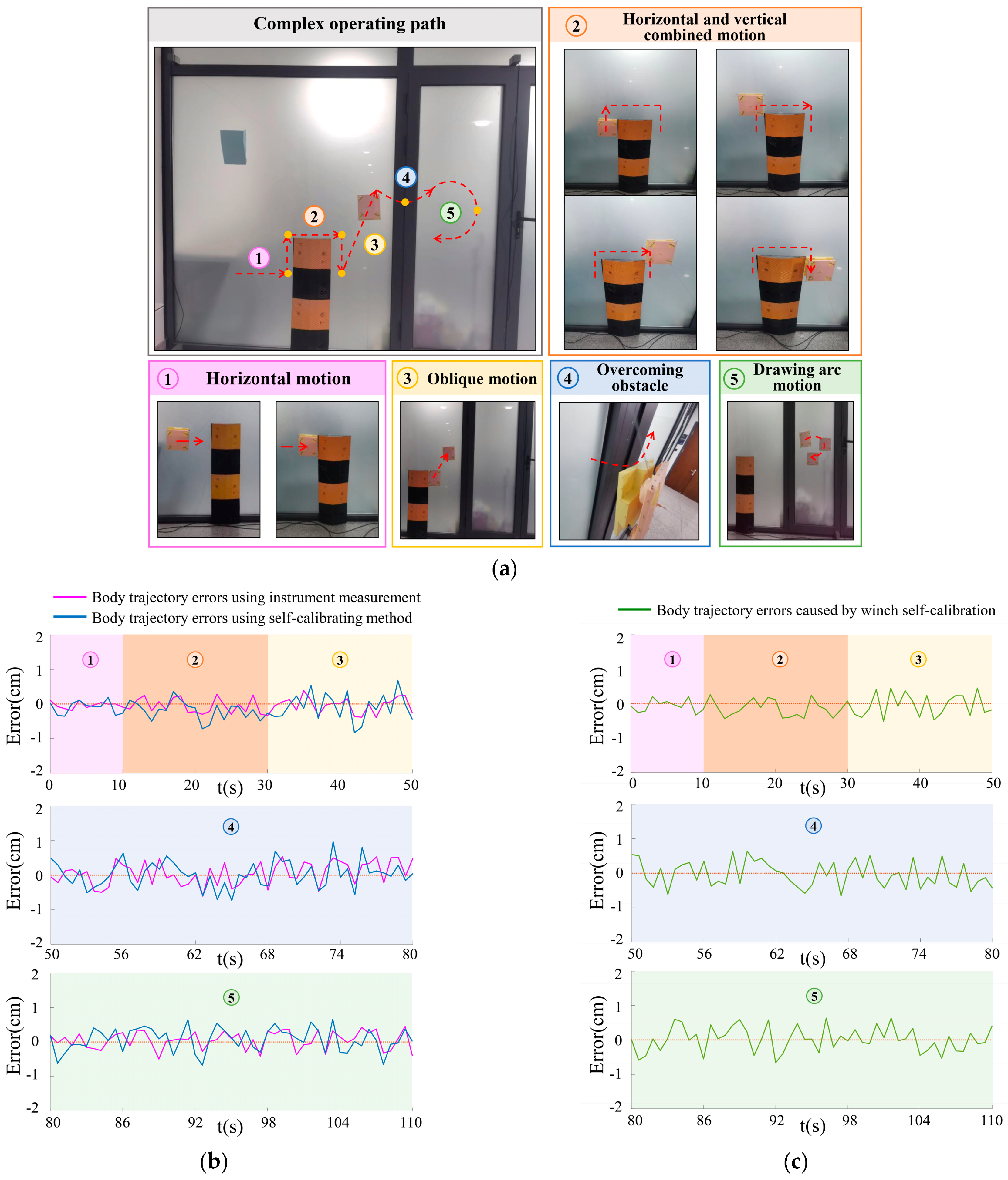
5.2. Trajectory Following Experiment

Accurate trajectory-following is the precondition for cleaning robots to ensure work efficiency and safety. The body can move along a planned trajectory accurately under ideal conditions, but the actual distance between the body and each winch might not be constantly equal to the measured rope length owing to the rope deformation; thus, the actual trajectory would deviate from the expected trajectory to varying degrees. Therefore, we conducted a series of body-centroid trajectory-following tests along various planned trajectories on the wall and compared the actual trajectory with the expected trajectory, as shown in Figure 11.
Figure 11a–e show the experimental results of five different types of motion. Each sub-figure contains an experimental photo, variation in length of each rope (rope 1−5), comparison of actual and ideal trajectories, and trajectory error (along its normal direction). Figure 11a shows that the maximum trajectory error is 1.9 mm, and variance is 1.38 × 10 2 mm2 as the body moves horizontally. Figure 11b shows that the maximum error is 2.7 mm, and variance is 3.09 × 10 2 mm2 as the body moves vertically. Figure 11c shows that the maximum error is 4.1 mm, and variance is 7.02 × 10 2 mm2 as the body moves obliquely. Figure 11d shows that the maximum error is 5.9 mm, and variance is 0.15 mm2 as the body overcomes an obstacle. Figure 11e shows that the maximum error is 5.2 mm, and variance is 0.12 mm2 as the body draws an arc.
Based on the above results, the robot has a favorable trajectory following performance in various directions with a maximum error of 5.9 mm, which meets the requirements of efficient and safe cleaning operations on complex walls.

5.3. Winch Calibration Experiment

Winch calibration is the precondition of normal operation and accurate movement for rope-driven robots; however, complex surroundings inevitably increase the difficulty of traditional calibration using instruments. Thus, we proposed a winch self-calibration method and conducted a verification experiment.
The position accuracy of winch calibration will be reflected in the body-moving trajectory; so, observing trajectory errors is a common way to indirectly evaluate the effect of the self-calibration method. Using laser instruments to directly measure winch positions can maintain high precision indoors; therefore, its body trajectory can be regarded as a reference value. Thus, by comparing the trajectory errors obtained using instrument measurement and the self-calibration method, the influence of the winch self-calibration on the body trajectory can be determined.
To comprehensively verify the method, we designed a complex body operating path with multiple motions that can be divided into five sections. The Section 1 is the horizontal motion, the Section 2 includes the horizontal and vertical motions, the Section 3 is the oblique motion, the Section 4 is the obstacle-overcoming motion, and the Section 5 is the drawing arc motion, as shown in Figure 12a.
Since the calibrated winch positions will be applied to the rope length solution and body trajectory planning, winch position errors caused by the self-calibration method might cause the actual trajectory to deviate from the reference trajectory. We used this method to calibrate winches and obtained the body trajectory with a maximum error of 9.6 mm, while the maximum error using laser instruments is 6.5 mm, as shown in Figure 12b. The results show that the self-calibration method can achieve similar positioning accuracy compared to instrument measuring.
From the above results, there are also some errors in the body trajectory when using a laser instrument to position winches, indicating that the experiment is also affected by other non-winch calibration factors. To exclude the impacts and display the performance of the self-calibration method more visually, we subtracted the body trajectory errors using instruments from the errors using the self-calibration method, and acquired body trajectory errors caused by winch self-calibration, as shown in Figure 12c.
The results show that the maximum trajectory error is 6.6 mm, indicating that the method has tiny interferences on the body trajectory. Thus, the winch positioning accuracy is sufficient, proving the feasibility of the method. Furthermore, using the self-calibration method to replace instrument measurement can greatly reduce the restrictions of wall appearance and external environments, and improve the convenience of position calibration significantly, thereby expanding the application scenes of rope-driven robots.

6. Discussion

Results show that the robot could safely overcome obstacles of more than 300 mm on the walls, and adapt to curved surfaces with different orientations and curvatures. Meanwhile, the robot shows relatively strong stability due to the redundant design. It also has a favorable trajectory following performance in various directions with a maximum error of 5.9 mm. In view of several key properties of the rope-driven cleaning robot, our robot is compared with the existing robots, as shown in Table 2. Our robot shows relatively strong obstacle-crossing performance, which is significantly better than other robots. This expands the operational area per session and enhances efficiency. In addition, our robot has a unique surface adaptation capability that is not found in other robots, which is conducive to ensuring the cleaning effect. However, winch 5 must be installed a certain distance in front of the glass (depending on the shape of the wall), which has higher requirements for space and might not be readily provided at all times. Furthermore, our robot moves relatively slowly and has no advantage over other robots when working on a flat surface. With a relatively strong obstacle-crossing capacity, our robot has a higher cleaning efficiency on complex walls.
The proposed method could realize the accurate calibration of winch positions with a maximum error of 6.6 mm, meeting the robot calibration requirements on complex walls. After adopting this method, the robot maintained precise movement along planned trajectories, and the maximum trajectory error was 9.6 mm. For rope-driven parallel robots, since there is no need to use professional instruments to directly measure the position of winches on the wall, this method greatly improves the convenience of position calibration. Meanwhile, it can avoid the instrument failure under harsh conditions to a certain extent. Thus, robot self-calibration is advantageous over manual measurement, although the calibration accuracy of the two schemes is comparable under normal circumstances. For the buildings with complex shapes or uncertain environments, the method can achieve relatively more convenient and accurate calibration.

7. Conclusions

For the global efficient cleaning of complex glass curtain walls, this paper presents a 3-DOF rope-driven robot and a self-calibration method. By integrating the 5-rope parallel configuration, self-adaptive cleaning body, and self-compensating driving winch, the robot can perform continuous, compliant, and accurate spatial motions on curved walls with obstacles. Based on the 3D kinematic model, the constraint relationship among winch positions, body positions, and rope lengths is established during robot movement. Through formulating a series of regulations to combine easily-measured body position and rope length parameters, a self-calibration method based on geometric analysis is proposed to accurately calculate winch positions without using professional instruments. A series of experiments were tailored to verify the performance of the robot and effectiveness of the method.
These enhancements address the limitations of existing robots in overcoming obstacles and surface adaptation, thereby improving the robot’s operational range and cleaning effect. Moreover, the proposed self-calibration method enables the convenient and precise positioning of winches installed on complex high-rise buildings, thereby simplifying the pre-configuration process of rope-driven robots. It provides a new concept for winch position calibration and can be used to solve the current application limitations of rope-driven cleaning robots. Therefore, this robot and the proposed method can be applied to cleaning tasks on more complex wall surfaces while ensuring operation efficiency, which can also be extended to other high-altitude fields such as large chemical storage tanks and solar panels. In future work, the parameters of the robot structure and performance of the self-calibration method can be further optimized to improve their accuracy, efficiency, and universality.

Author Contributions

Conceptualization, J.W., M.Z. and M.L.; methodology, J.W. and Y.L.; software, Y.L. and Z.L.; validation, Y.L. and Z.Z.; formal analysis, Y.L. and Y.B.; investigation, Y.L. and Y.B.; resources, M.Z.; data curation, Y.L.; writing—original draft preparation, J.W. and Y.L.; writing—review and editing, J.W., Y.L. and Y.B.; visualization, Z.L. and Z.Z.; supervision, M.Z. and M.L.; project administration, M.Z.; funding acquisition, M.Z, X.S. and M.L. All authors have read and agreed to the published version of the manuscript.

Funding

This research was funded by the National Natural Science Foundation of China (grant numbers: 52275016 and 52275017), the Insight Action Project (grant numbers: 62602010243), the Science and Technology Development Fund Project on Central Government Guiding Local Government (grant number: 226Z1801G and 226Z1811G), the Science and Technology Research Project of Colleges and Universities in Hebei Province (grant number: JZX2023015), Interdisciplinary Postgraduate Training Funding Project of Hebei University of Technology (grant number: HEBUT-Y-XKJC-2021108), State Key Laboratory of Reliability and Intelligence of Electrical Equipment (grant number: EERI_OY2021004), and S&T Program of Hebei (grant number: 225676163GH).

Data Availability Statement

Data are contained within the article.

Acknowledgments

The authors would like to thank the anonymous reviewers for their helpful comments and suggestions to improve the manuscript.

Conflicts of Interest

Authors declare no conflicts of interest.

References

  1. Feng, C.; Ma, F.; Wang, R. The operation characteristics analysis of a novel glass curtain wall system by using simulation and test. J. Build. Eng. 2022, 51, 104311. [Google Scholar] [CrossRef]
  2. Yan, H.; Niu, H.; Chang, Q.; Zhao, P.; He, B. Study on Dynamic Characteristics of Pipeline Jet Cleaning Robot. Actuators 2024, 13, 49. [Google Scholar] [CrossRef]
  3. Guo, T.; Deng, Z.D.; Liu, X. Development of a new hull adsorptive underwater climbing robot using the Bernoulli negative pressure effect. Ocean Eng. 2022, 243, 110306. [Google Scholar] [CrossRef]
  4. Bisht, R.S.; Pathak, P.M.; Panigrahi, S.K. Design and development of a glass facade cleaning robot. Mech. Mach. Theory 2022, 168, 104585. [Google Scholar] [CrossRef]
  5. Tun, T.T.; Elara, M.R.; Kalimuthu, M. Glass facade cleaning robot with passive suction cups and self-locking trapezoidal lead screw drive. Autom. Constr. 2018, 96, 180–188. [Google Scholar] [CrossRef]
  6. Sinkar, A.; Pandey, A.; Mehta, C. Design and development of wall climbing hexapod robot with SMA actuated suction gripper. Procedia Comput. Sci. 2018, 133, 222–229. [Google Scholar] [CrossRef]
  7. Vega-Heredia, M.; Elara Mohan, R.; Wen, T.Y. Design and modelling of a modular window cleaning robot. Autom. Constr. 2019, 103, 268–278. [Google Scholar] [CrossRef]
  8. Kim, T.; Kim, J.; Seo, K.; Kim, H.; Lee, G.; Kim, J.; Kim, H. Design and control of a cleaning unit for a novel wall-climbing robot. Appl. Mech. Mater. 2014, 541, 1092–1096. [Google Scholar] [CrossRef]
  9. Seo, T.; Jeon, Y.; Park, C.; Kim, J. Survey on glass and facade-cleaning robots: Climbing mechanisms, cleaning methods, and applications. Int. J. Precis. Eng. Manuf.-Green Technol. 2019, 6, 367–376. [Google Scholar] [CrossRef]
  10. Schraft, R.; Bräuning, U.; Orlowski, T.; Hornemann, M. Automated cleaning of windows on standard facades. Autom. Constr. 2000, 9, 489–501. [Google Scholar] [CrossRef]
  11. Zhang, H.; Zhang, J.; Zong, G. Sky Cleaner 3: A real pneumatic climbing robot for glass-wall cleaning. IEEE Robot. Autom. Mag. 2006, 13, 32–41. [Google Scholar] [CrossRef]
  12. Shao, L.; Xing, Y.; Li, J. Adsorption mechanism analysis of photovoltaic cleaning robot based on negative pressure adsorption. In Proceedings of the 2018 Chinese Control and Decision Conference (CCDC), Shenyang, China, 9–11 June 2018; pp. 4133–4137. [Google Scholar]
  13. Zhou, Q.; Li, X. Experimental investigation on climbing robot using rotation-flow adsorption unit. Robot. Auton. Syst. 2018, 105, 112–120. [Google Scholar] [CrossRef]
  14. Lee, Y.S.; Kim, S.H.; Gil, M.S. The study on the integrated control system for curtain wall building facade cleaning robot. Autom. Constr. 2018, 94, 39–46. [Google Scholar] [CrossRef]
  15. Akinfiev, T.; Armada, M.; Nabulsi, S. Climbing cleaning robot for vertical surfaces. Ind. Robot 2009, 36, 352–357. [Google Scholar] [CrossRef]
  16. Dai, H. Design of high-altitude curtain wall cleaning robot. In Proceedings of the 2020 3rd World Conference on Mechanical Engineering and Intelligent Manufacturing (WCMEIM), Shanghai, China, 4–6 December 2020; pp. 157–160. [Google Scholar]
  17. Seo, K.; Cho, S.; Kim, T. Design and stability analysis of a novel wall-climbing robotic platform (ROPE RIDE). Mech. Mach. Theory 2013, 70, 189–208. [Google Scholar] [CrossRef]
  18. Mamidi, T.K.; Bandyopadhyay, S. Forward dynamic analyses of cable-driven parallel robots with constant input with applications to their kinetostatic problems. Mech. Mach. Theory 2021, 163, 104381. [Google Scholar] [CrossRef]
  19. Idà, E.; Mattioni, V. Cable-driven parallel robot actuators: State of the art and novel servo-winch concept. Actuators 2022, 11, 290. [Google Scholar] [CrossRef]
  20. González-Rodríguez, A.; Martín-Parra, A.; Juárez-Pérez, S.; Rodríguez-Rosa, D.; Moya-Fernández, F.; Castillo-García, F.J.; Rosado-Linares, J. Dynamic model of a novel planar cable driven parallel robot with a single cable loop. Actuators 2023, 12, 200. [Google Scholar] [CrossRef]
  21. Esfandiyar, H.; Daneshmand, S.; Kermani, D. On the control of a single flexible arm robot via Youla-Kucera parameterization. Robotica 2016, 34, 150–172. [Google Scholar] [CrossRef]
  22. Lu, B.; Fang, Y.; Sun, N. Nonlinear control for underactuated multi-rope cranes: Modeling, theoretical design and hardware experiments. Control Eng. Pract. 2018, 76, 123–132. [Google Scholar] [CrossRef]
  23. Zhang, Z.; Xie, G.; Shao, Z. Kinematic calibration of cable-driven parallel robots considering the pulley kinematics. Mech. Mach. Theory 2022, 169, 104648. [Google Scholar] [CrossRef]
  24. Esfandiyar, H.; Korayem, M.H. Accurate nonlinear modeling for flexible manipulators using mixed finite element formulation in order to obtain maximum allowable load. J. Mech. Sci. Technol. 2015, 29, 3971–3982. [Google Scholar] [CrossRef]
  25. Esfandiyar, H.; Korayem, M.H.; Haghpanahi, M. Large deformation modeling of flexible manipulators to determine allowable load. Struct. Eng. Mech. 2017, 62, 619–629. [Google Scholar]
  26. Elkmann, N.; Kunst, D.; Krueger, T. SIRIUSc—Facade cleaning robot for a high-rise building in Munich. In Climbing and Walking Robots; Springer: Berlin/Heidelberg, Germany, 2005; pp. 1033–1040. [Google Scholar]
  27. Miermeister, P.; Lachele, M.; Boss, R. The cable robot simulator large scale motion platform based on cable robot technology. In Proceedings of the 2016 IEEE/RSJ International Conference on Intelligent Robots and Systems (IROS), Daejeon, Republic of Korea, 1 December 2016; pp. 3024–3029. [Google Scholar]
  28. Sun, C.; Gao, H.; Liu, Z. Design and optimization of three-degree-of-freedom planar adaptive cable-driven parallel robots using the cable wrapping phenomenon. Mech. Mach. Theory 2021, 166, 104475. [Google Scholar] [CrossRef]
  29. Yoo, S.; Kim, T.; Seo, M. Position-tracking control of dual-rope winch robot with rope slip compensation. IEEE/ASME Trans. Mechatron. 2021, 26, 1754–1762. [Google Scholar] [CrossRef]
  30. Sûr Efficace et Durable Avec des Résultats Transparents, The Netherlands 2019. Available online: https://www.kiterobotics.com (accessed on 18 March 2024).
  31. Sato, O.; Shimojima, K.; Furutani, R. Artefact calibration of parallel mechanism, kinematic calibration with a priori knowledge. Meas. Sci. Technol. 2004, 15, 1158. [Google Scholar] [CrossRef]
  32. Du, L.; Zhang, T.; Dai, X. Compliance error calibration for robot based on statistical properties of single joint. J. Mech. Sci. Technol. 2019, 33, 1861–1868. [Google Scholar] [CrossRef]
  33. Mauricio, A.; García-Murillo, M.A.; Cervantes-Sánchez, J.J.; Torres, F.J.; Moreno-Avalos, H.A. Identification of geometric parameters of a parallel robot by using a camera calibration technique. J. Mech. Sci. Technol. 2021, 35, 729–737. [Google Scholar]
  34. Capua, A.; Shapiro, A.; Shoval, S. Spider Bot: A cable suspended mobile robot. In Proceedings of the 2011 IEEE International Conference on Robotics and Automation, Shanghai, China, 9–13 May 2011; pp. 3437–3438. [Google Scholar]
  35. Wang, D.; Ahn, J.; Jung, J. Winch-integrated mobile end-effector for a cable-driven parallel robot with auto-installation. Int. J. Control Autom. Syst. 2017, 15, 2355–2363. [Google Scholar] [CrossRef]
Figure 1. Overall structure of the cleaning robot: (a) Spatial 5-rope parallel configuration; (b) Self-adaptive cleaning body; (c) Self-compensating driving winch.
Actuators 13 00272 g001
Figure 2. Working principle of the cleaning robot: (a) Obstacle overcoming process; (b) Curved surface self-adaption; (c) Accurate driving.
Actuators 13 00272 g002
Figure 3. Kinematic model: (a) Rope length solution; (b) Body position solution.
Actuators 13 00272 g003
Figure 4. The regulations of winch self-calibration.
Actuators 13 00272 g004
Figure 5. Geometric analysis of step 2.
Actuators 13 00272 g005
Figure 6. Geometric analysis of step 3.
Actuators 13 00272 g006
Figure 7. Geometric analysis of step 4.
Actuators 13 00272 g007
Figure 8. Experimental platform.
Actuators 13 00272 g008
Figure 9. Obstacle-overcoming experiments.
Actuators 13 00272 g009
Figure 10. Surface adaption experiments: (a) Adaption to horizontal curved surface; (b) Adaption to vertical curved surface.
Actuators 13 00272 g010
Figure 11. Trajectory following experiments: (a) Horizontal motion trajectory; (b) Vertical motion trajectory; (c) Oblique motion trajectory; (d) Overcoming-obstacle trajectory; (e) Drawing arc motion trajectory.
Actuators 13 00272 g011
Figure 12. Winch self-calibration method verification: (a) Complex body-operating path; (b) Body trajectory errors using two ways; (c) Body trajectory errors caused by the self-calibration method.
Actuators 13 00272 g012
Table 1. Experimental parameters.
Componentx-Axis (m)y-Axis (m) z-Axis (m)
Winch 102.500
Winch 23.002.500
Winch 3000
Winch 43.0000
Winch 51.5003.00
Cleaning body1.371.120
Doorframe obstacle1.841.120
Curved surface 10.551.680
Curved surface 21.300.430
Table 2. Robot performance comparison.
Robot Obstacle Overcoming Height (mm)Surface Adaption CapacityTraverse Speed
(cm/s)
ROPERIDE [8]0–100No22.5
Manntech [9]0–100No5.5
SFRII [10]0–100No2.0
TITO [15]0–100No0.5
Our robotOver 300Yes2.2
Disclaimer/Publisher’s Note: The statements, opinions and data contained in all publications are solely those of the individual author(s) and contributor(s) and not of MDPI and/or the editor(s). MDPI and/or the editor(s) disclaim responsibility for any injury to people or property resulting from any ideas, methods, instructions or products referred to in the content.

