Article

A High Torque Density Dual-Stator Flux-Reversal-Machine with Multiple Poles Halbach Excitation on Outer Stator

by
Siwei Tang
,
Yuanying Xu
,
Chao He
and
Jiquan Yang
*
School of Electrical and Automation Engineering, Nanjing Normal University, Nanjing 210023, China
*
Author to whom correspondence should be addressed.
Actuators 2024, 13(8), 275; https://doi.org/10.3390/act13080275
Submission received: 29 May 2024 / Revised: 9 July 2024 / Accepted: 19 July 2024 / Published: 23 July 2024
(This article belongs to the Section High Torque/Power Density Actuators)

Abstract

:
This paper proposes a high torque density dual-stator flux-reversal-machine with multiple poles Halbach excitation (MPHE-DSFRM), which uses two pole pairs’ numbers (PPNs) of PM excitation on one outer stator tooth, and one PPN of PM excitation on one inner stator tooth. The introduction of different PPNs of PM excitation on the outer and the inner stators can optimize magnetic circuit and airgap flux density. A Halbach array is formed by inserting three pieces of circumferentially magnetized PMs into four pieces of radially magnetized permanent magnets (PMs) on the outer stator, which aims to further enhance torque density, and reduce torque ripple. Based on the flux modulation effect, the analytical modeling of the proposed MPHE-DSFRM is established, together with the evolution process, and the working principle is presented. Then, the key design parameters of MPHE-DSFRM are optimized to achieve high torque density and low torque ripple for high torque quality. Three representative DSFRMs and a conventional FRM are designed and analyzed, and they share the same design key parameters, including PM usage, outer radius of the outer stator, and active airgap length. The electromagnetic performances, including airgap flux density, back electromotive force (back-EMF), and torque characteristics, are analyzed and compared by finite element analysis (FEA). The calculated results show that the proposed MPHE-DSFRM can provide high torque density and high PM utilization.

1. Introduction

Permanent magnet synchronous machines (PMSMs) have been widely used in high-performance applications, including electric vehicles (EVs) and aerospace exploration, due to their excellent performance, high efficiency, and high power [1,2]. The high-speed PMSMs are usually combined with mechanical gear to form drive systems, which can effectively increase the torque density [3]. However, the employment of mechanical gear will lead to acoustic and vibration issues, which cause low reliability during operation [4]. In order to solve this problem, the magnetic gear is proposed to design flux modulation machines (FMMs) [5,6,7]. In FMMs, a low-speed harmonic field can be obtained from a high-speed armature magnetic field modulated by a modulator, which is then coupled with a low-speed rotating magnetic field that is excited by PMs to produce a high output torque [8,9]. Therefore, FMMs can achieve the merit of high torque at low-speed, which further enhances torque density [10,11,12,13,14]. To avoid PM falling off, and to improve heat dissipation performance, stator PM FMMs, including flux reversal machines (FRM) and flux switching machines (FSMs), are designed [15,16,17,18]. FRMs have simple topology and lower manufacturing difficulty compared to FSMs, but the space utilization of FRMs is low, limiting the increase on torque output. To solve this problem, a dual-stator (DS) structure is introduced, which can offer high space utilization and control flexibility [19,20]. In [21], two novel dual-stator machines with different biased PM configurations are designed and comparatively studied, in which the space tradeoff between PM and copper areas, and severe magnetic saturation, is significantly alleviated. In [22], biased PM excitation is introduced in the inner stator of a DS machine, through which we can maximize the torque capability with the constraint of copper loss. In [23], two stators, sandwiched rotor, and consequent-pole structure are employed to design the dual-stator consequent-pole PM vernier machine, through which high torque density and low cost can be achieved. However, PMs of these DS machines are located on the rotor or stator alone, which may limit further torque promotion. Then, dual-stator machines with dual PM excitation are proposed [24,25,26,27,28], in which both the outer and the inner stators can apply PMs for providing rich working harmonics for high torque output. However, a large usage of PM may cause high saturation, which leads to significant temperature rise and life shortening issues. Furthermore, typical DSFRMs with PM excitation in both the outer and inner stators can enhance the torque [29,30,31], but the identical inner and outer stator structures are changed to improve characteristic diversification [32,33].
To solve these problems, this paper proposes a new dual-stator flux-reversal-machine with multiple poles Halbach excitation (MPHE-DSFRM), which uses two pole pairs’ numbers (PPNs) of PM excitation on one outer stator tooth, and one PPN of PM excitation on one inner stator tooth. The introduction of different PPNs of PM excitation on the outer and the inner stators can optimize magnetic circuit and airgap flux density. The Halbach array is formed by inserting three pieces of circumferentially magnetized PMs into four pieces of radially magnetized permanent magnets (PMs) on the outer stator, which aims to further enhance torque density, reduce torque ripple, and suppress the risk of saturation. The evolution process from the conventional FRM and working principle of the MPHE-DSFRM are provided. The main contributions of this paper are summarized as follows:
(1) The analytical modeling of proposed MPHE-DSFRM is established, which takes the different PPNs of PM excitation on stators into consideration.
(2) The key parameters, including the position between the two stators, the position between the outer and inner teeth on the rotor, and the angle difference between the outer and the inner teeth on the rotor of the proposed machine are defined and optimized, and they are apparently different from the investigations of the conventional DSFRMs.
This paper will be organized as follows. In Section 2, the design and evolution process of MPHE-DSFRM are provided, together with the presented working principle. In Section 3, four investigated machines are designed through sensitivity analysis of key parameters. In Section 4, the electromagnetic performances are comparatively analyzed by finite element analysis (FEA), which verifies the merits of high torque density and high PM utilization in the proposed MPHE-DSFRM.

2. Evolution Process of Topology and Operating Principle

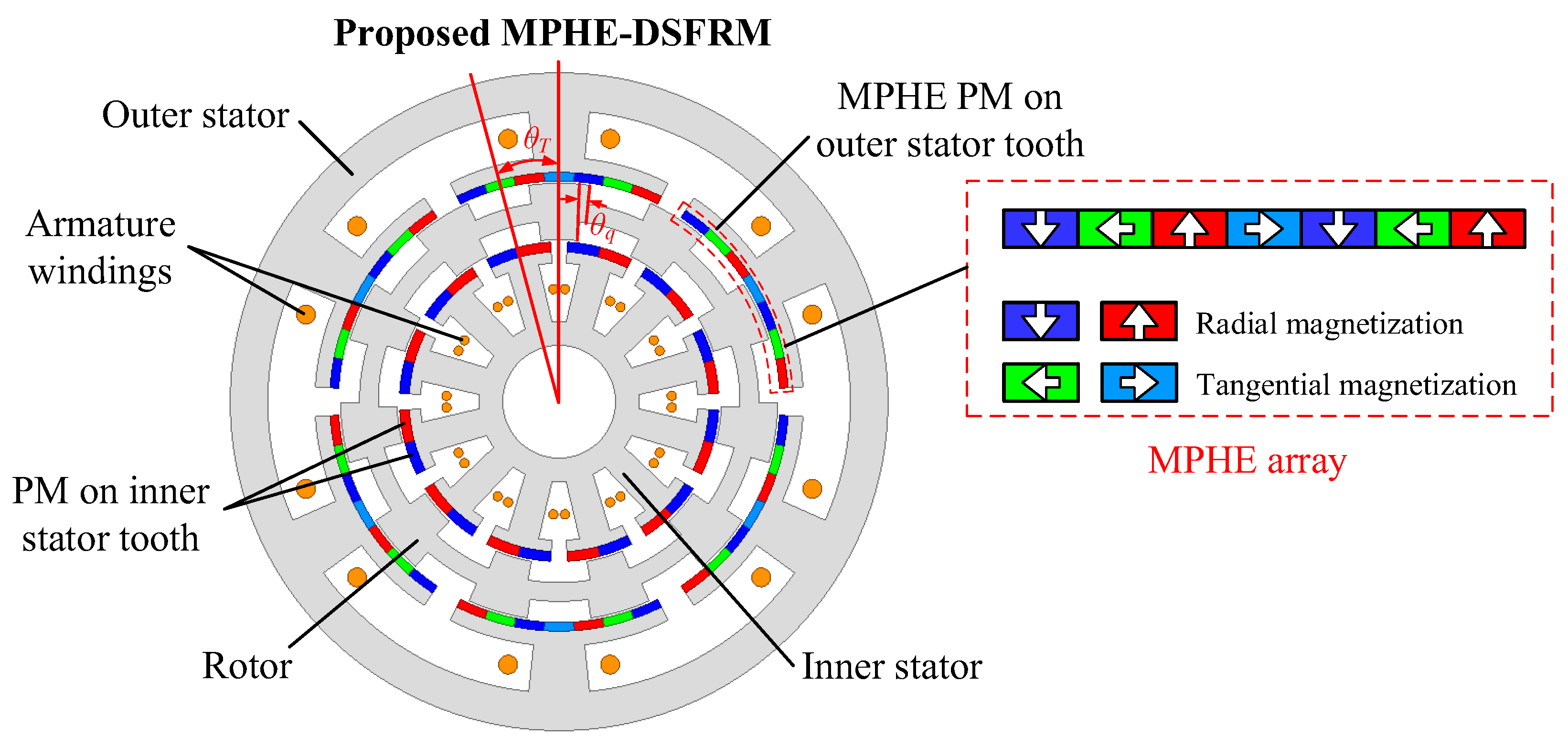
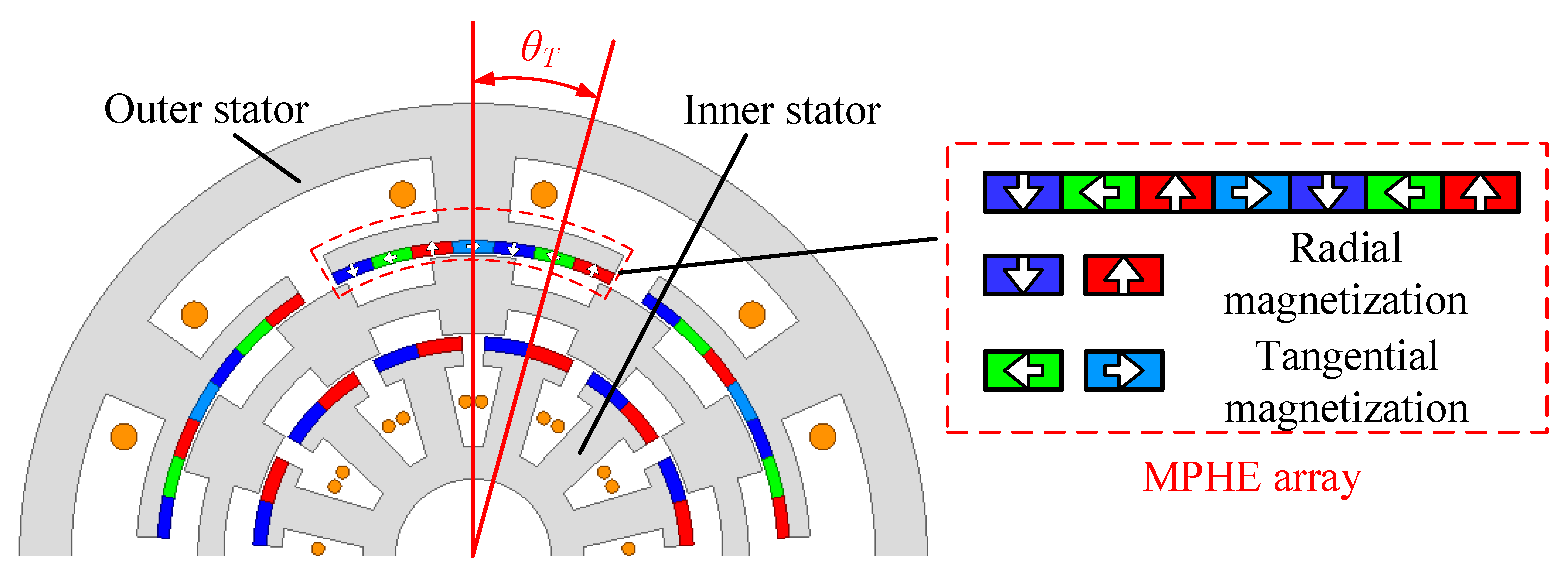
2.1. Machine Configuration

Figure 1 shows the configuration of the proposed MPHE-DSFRM, in which the rotor is sandwiched by the outer and inner stator. The proposed MPHE-DSFRM can be considered as an external FRM with four poles PMs on each stator tooth, and an internal FRM with two poles PMs on each stator tooth. Based on the pole/slot combination, outer and inner stators use six stator slots and twelve stator slots when having the same pole pair number (PPN) of PMs, respectively. The Halbach array is employed to reduce leakage flux, improve PM utilization, and reduce the torque ripple of the machine [34,35]. High torque density can be obtained by optimizing the positions of the two stators (θT) and the angle difference between the width of inner and outer salient rotor poles (θq). The relationship between the number of rotor salient poles, the PPN of stator PM, and the armature reaction follows the field modulation theory.

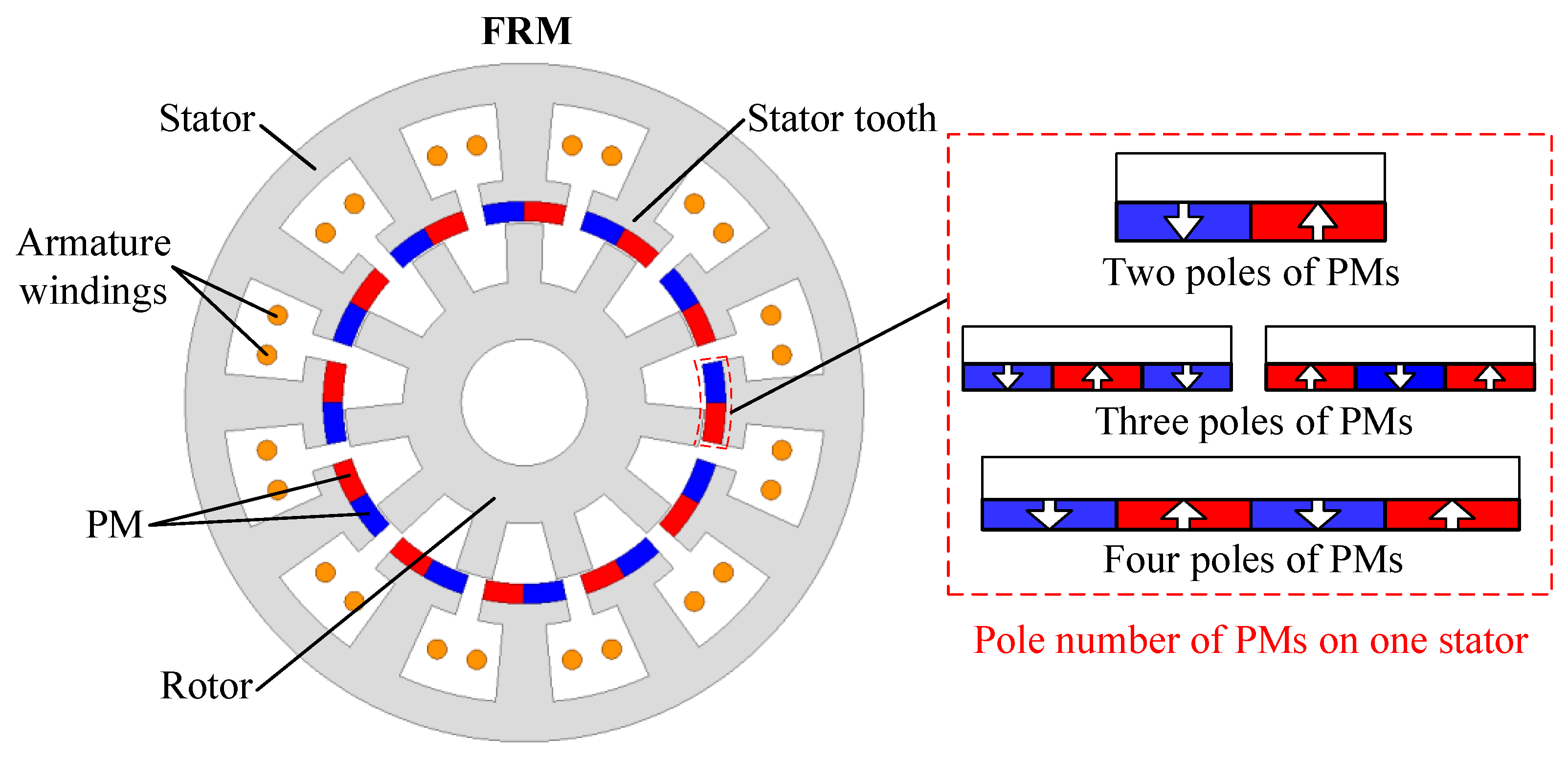
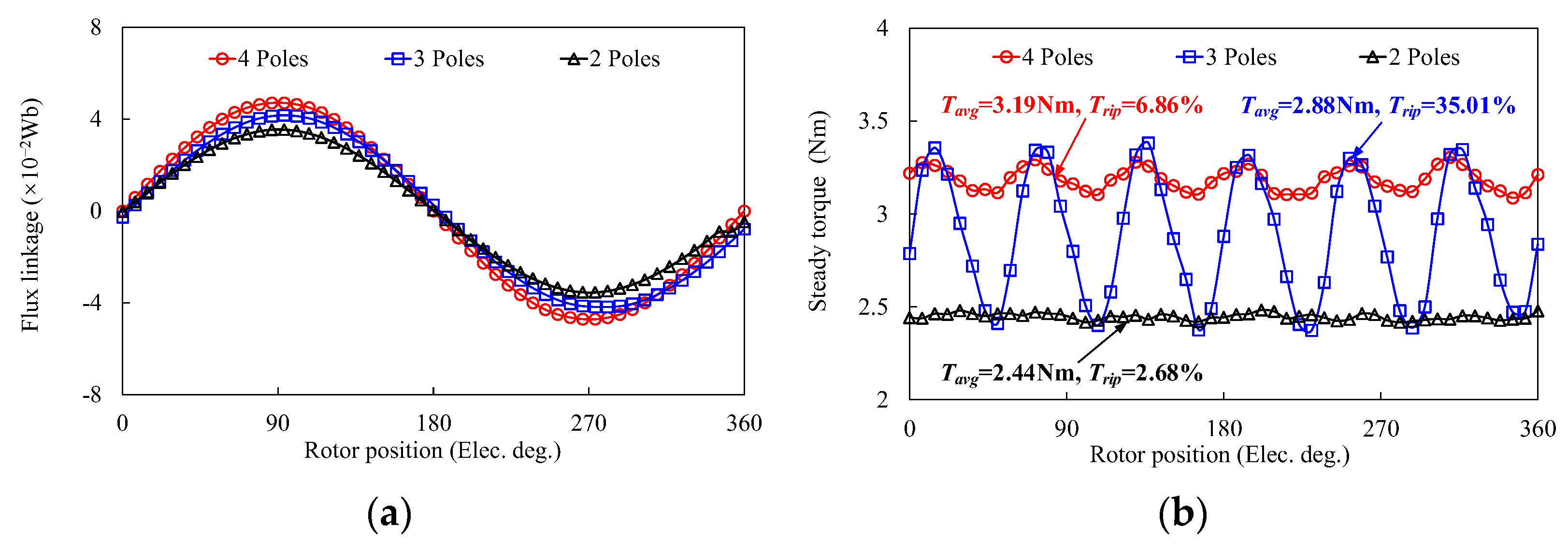
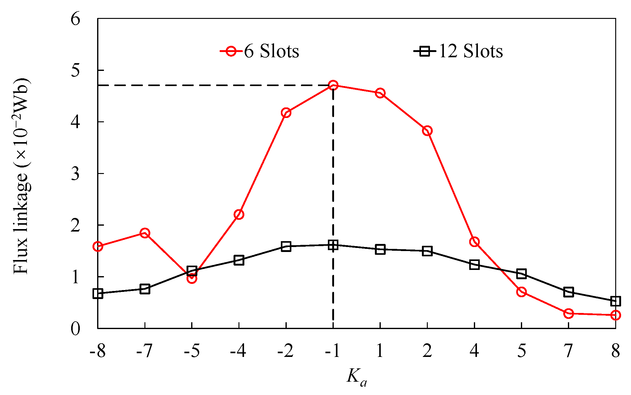
2.2. PM Poles Selection

Figure 2 shows the topology of FRM with different poles of PMs on one stator tooth. For the conventional FRM, two adjacent radial magnetization PMs with opposite polarity are mounted on the top of the stator tooth, which can build the main flux path. The salient pole rotor is employed to transmit the magnetic torque and force the magnetic field to rotate. Based on flux modulation theory, FRM can employ a different flexible pole/slot combination. Therefore, arrangements of multiple three and four poles of PMs can be used on one stator tooth to enhance the output torque. The comparison of FRM to different poles of PMs on one stator tooth is depicted in Figure 3. It shows that the amplitude of the steady torque can be enhanced with more than two poles of PMs on one stator tooth, which agrees with the variation of flux linkage. However, the torque ripple of FRM with three poles of PMs on the stator tooth has a significant increase, which is mainly due to lower symmetry on the PM circumferential distribution. Furthermore, structures with PMs exceeding four poles will significantly increase the flux leakage and manufacturing difficulty, which are not taken into account. Therefore, the structure of multiple four poles of PMs on each stator tooth can effectively increase flux linkage and torque output, compared to two poles of PMs.

2.3. Armature Winding Configuration

According to the aforementioned analysis, four poles of PMs on one stator tooth can enhance the torque output for FRM. Then, different combinations of pole/slot can be obtained, based on flux modulation. Since odd-slot machines have an odd number of slots per phase and, therefore, cannot form complementary windings, they have a poor sinusoidal no-load back electromotive force (back-EMF), and reduce the torque of the machine. Therefore, the main consideration is for six-slot and twelve-slot configurations without considering the design of odd slots. The corresponding PPN of armature windings, pitch factor kd, distribution factor kp, winding factor kw, amplitudes of the base wave amplitude of the back-EMF Ub, and flux linkage ψf of the FRM with different rotor salient pole number combinations are listed in Table 1. Moreover, the trend of the amplitude of the flux linkage with the different PPNs of the armature winding is shown in Figure 4.
The parameter Ka is defined as the difference between the number of rotor salient poles (Zr) and the PPN of stator PM (Ps), which is expressed as
K a = Z r P s
The Ka may be negative when ZrPs, which has the range from −8 to 8. It can be seen that the amplitude of flux linkage of the six-slot winding configuration is higher than that of the twelve-slot winding configuration when −4 ≤ Ka ≤ 4. Additionally, the structure with fewer Zr has better performance than that with more Zr when the absolute value of Ka is the same. The amplitude of flux linkage decreases dramatically when Zr ≥ 16 for the six-slot winding, and Zr ≥ 29 for twelve-slot winding, which is mainly due to significant flux leakage. To obtain a higher back-EMF and a superior flux-modulated effect, the FRM with four poles of PMs on one stator tooth and Ns = 6, Zr = 11 can be designed. It should be noted that the six-slot stator is designed to keep the same PPN of PMs after employing four poles of PM on one stator tooth.

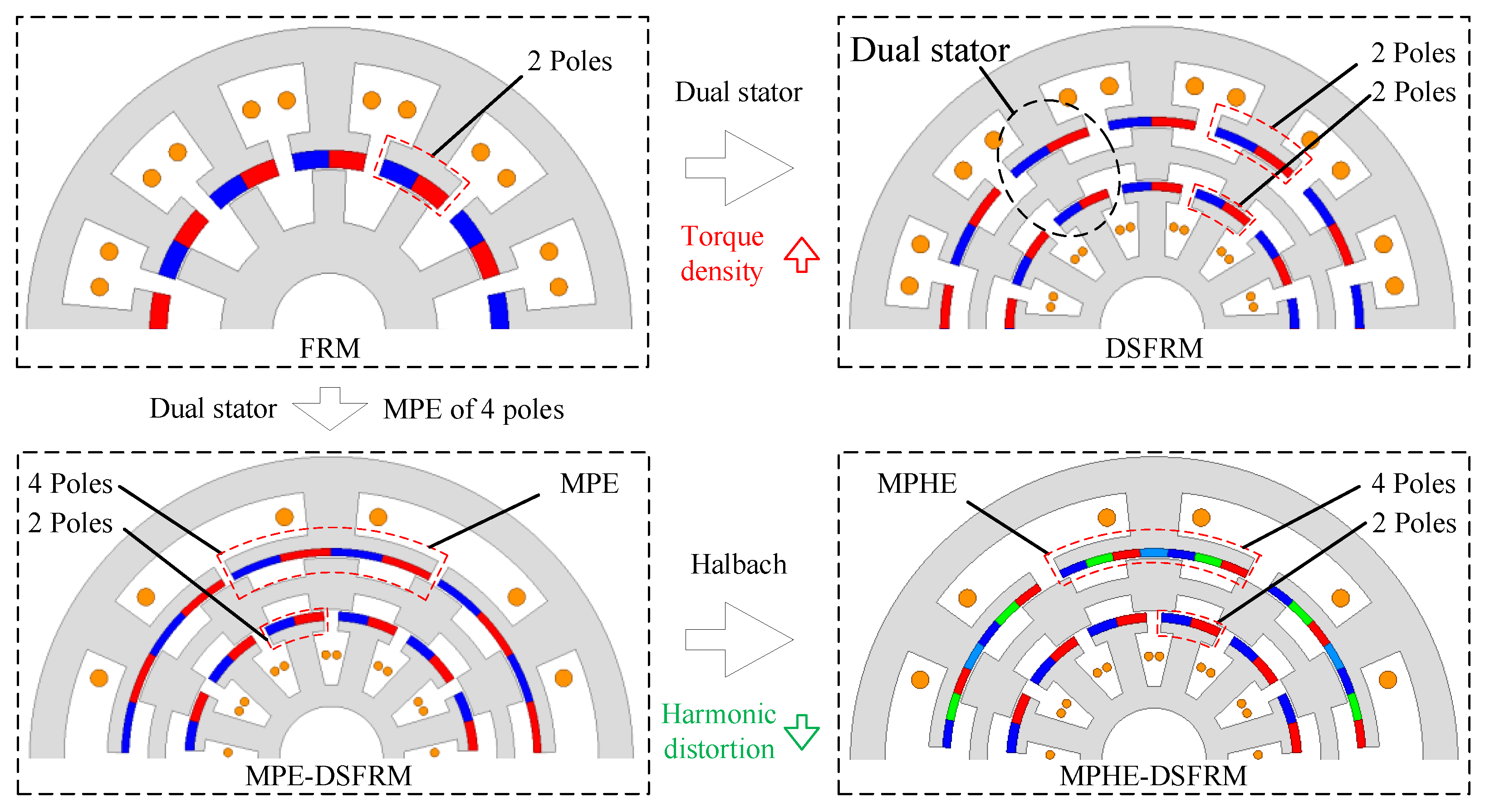
2.4. Evolution Process

Figure 5 shows the evolution process of the proposed MPHE-DSFRM from the conventional FRM. DSFRM can be designed after employing dual-stator structure, which has the merits of high torque density and high space utilization. The DSFRM has inner and outer stators and double-layer salient poles in the rotor, which can be considered as external and internal FRMs. To further enhance the torque density, four poles of PMs on one stator tooth can be introduced, which forms the MPE-DSFRM with Ns = 6 in external FRM, and Ns = 12 in internal FRM. In order to further enhance torque density, reduce torque ripple, and suppress risk of magnetic saturation, a Halbach array is employed on the outer stator to achieve both merits of high torque density and low harmonic distortion.

2.5. Operating Principle

According to the characteristics of the geometrical configuration shown in Figure 1 and Figure 5, the proposed MPHE-DSFRM can be separated into two sections, i.e., one outer FRM with four poles of PMs on each stator tooth, and one inner FRM with two poles of PMs on each stator tooth. Therefore, the theoretical analysis of the proposed MPHE-DSFRM can be regarded as two separated machines for analysis [36]. The magnetomotive force (MMF) is mainly provided by PMs on the inner and outer stators. Based on fast Fourier decomposition, the PM MMF of investigated machines can be expressed as
F o ( θ s ) = j = 1.3 , 5 F o j cos ( i P o e θ s ) F o j = 2 F S 2 π m [ 1 cos ( 2 m λ P M 2 π ) ] ,   k = 2 F S 4 2 π m [ 2 cos ( m ( λ 14 + 2 λ P M 4 ) π ) + 2 cos ( m ( 2 λ P M 4 + 3 λ 14 ) π ) 2 cos ( m ( 1 λ 04 ) π ) 2 cos ( m λ 14 π ) ] ,   k = 4
F i ( θ s ) = j = 1.3 , 5 F i j cos ( i P i e θ s ) F i j = 2 F S 2 π m [ 1 cos ( 2 m λ P M 2 π ) ] ,   k = 2
where Fo and Fi are the PM MMFs of the outer and inner FRMs. Foj and Fij are the Fourier coefficients of MMF. Poe and Pie are the PPNs of outer and inner stator PMs, respectively. θs is the position angle. FS2 and FS4 are the amplitudes of MMF. λPM2 and λPM4 are the pole arc coefficients of two poles and four poles PMs. λ04 and λ14 are the pole arc coefficients of the tangential magnetization PM in the Halbach array. k is the poles number of PMs.
Based on flux modulation theory, the flux densities in the inner and outer airgaps are modulated by salient rotor teeth. Then, the equivalent permeance from the salient rotor can be expressed as follows [37,38]:
Λ o ( θ s , t ) Λ o 0 + Λ o 1 cos ( Z r θ s ω r t )
Λ i ( θ s , t ) Λ i 0 + Λ i 1 cos ( Z r θ s ω r t )
where Λo0 and Λo1 are the Fourier coefficient of the outer FRM permeance function, respectively. Λi0 and Λi1 are the Fourier coefficient of the inner FRM permeance function, respectively. Zr is the number of rotor salient poles. Based on the flux modulation effect, the relationships of PPNs of armature reaction (Poa and Pia), the PPN of stator PMs, and number of rotor salient poles should satisfy the following:
i P o a = n P o e + m Z r n = 1 , 2 , 3 , m = 0 , 1 , 2 ,
i P i a = n P i e + m Z r n = 1 , 2 , 3 , m = 0 , 1 , 2 ,
Then, based on the magnetic circuit principle, the no-load airgap flux density distribution can be given as follows:
B o ( θ s , t ) = F o ( θ s ) Λ 0 ( θ s , t )
B i ( θ s , t ) = F i ( θ s ) Λ i ( θ s , t )
The winding function of the stator winding can be expressed as
N o ( θ s ) = 4 N w o π n = 1 , 3 , 5 sin n θ s o n
N i ( θ s ) = 4 N w i π i = 1 , 3 , 5 sin n θ s i n
where Nwo and Nwi are the number of turns of armature windings in the outer and inner stators. θso is the angle between the center line of the rotor and outer stator teeth. θsi is the angle between the center line of the rotor and inner stator teeth. The PM flux linkage of phase-A can be obtained through the integration of the product by airgap flux density and the winding function, derived above as
ψ ( t ) = k a L a x r g a p 0 2 π B ( θ s , t ) N ( θ s ) d θ
where ka is the winding factor, Lax is the axial length of machine, and rgap is the radius of airgap. Then, the phase back-EMF can be expressed as the derivative of PM flux-linkage to time t, according to the Faraday law, as shown in (13).
e = d ψ d t
Therefore, the phase back-EMF of MPHE-DSFRM can be obtained by combining Equations (8)–(13), as shown in Equations (14) and (15).
e o ( t ) = d ( k a o L a x r o 0 2 π B o ( θ s , t ) N o ( θ s ) d θ s ) d t
e i ( t ) = d ( k a i L a x r i 0 2 π B i ( θ s , t ) N i ( θ s ) d θ s ) d t
where kao and kai are the winding factors of the outer and inner armature windings, respectively. ro and ri are the radius of the outer and inner airgaps, respectively. Then, back-EMF of the proposed machine can be obtained as follows
e ( t ) = e o ( t ) + e i ( t )
Meanwhile, the harmonics distributions of the airgap flux density of MPHE-DSFRM are depicted in Figure 6. It can be seen that the analytical results have a good agreement with FEA results, which confirms the correctness of the predicted modulation process and analytical modeling.

3. Key Parameters Design of the Proposed MPHE-DSFRM

The excellent torque performance can be evaluated by high torque quality (TQ) [37]. Therefore, the objectives of the maximum average torque (Tavg) and minimum torque ripple (Trip) are pursued in the proposed MPHE-DSFRM. The TQ and Trip are defined as
T Q = T a v g T r i p × 100 T r i p = T max T min T a v g × 100 %
where Tmax and Tmin are the maximum and minimum values of steady torque waveform, respectively. Therefore, the key parameters of the investigated machines should be optimized. Considering the main differences between dual-stators and conventional one stator, the key parameters, including the position between two stators, width of the PM, width of the salient pole, the position between the outer and inner teeth on the rotor, and the angle difference between the outer and inner teeth on the rotor, are defined and optimized. For a fair comparison, the key parameters, including outer and inner diameters, active stack length, and airgap length, are kept the same during the optimization process. In addition to this, the other design parameters have been optimized for high torque quality.

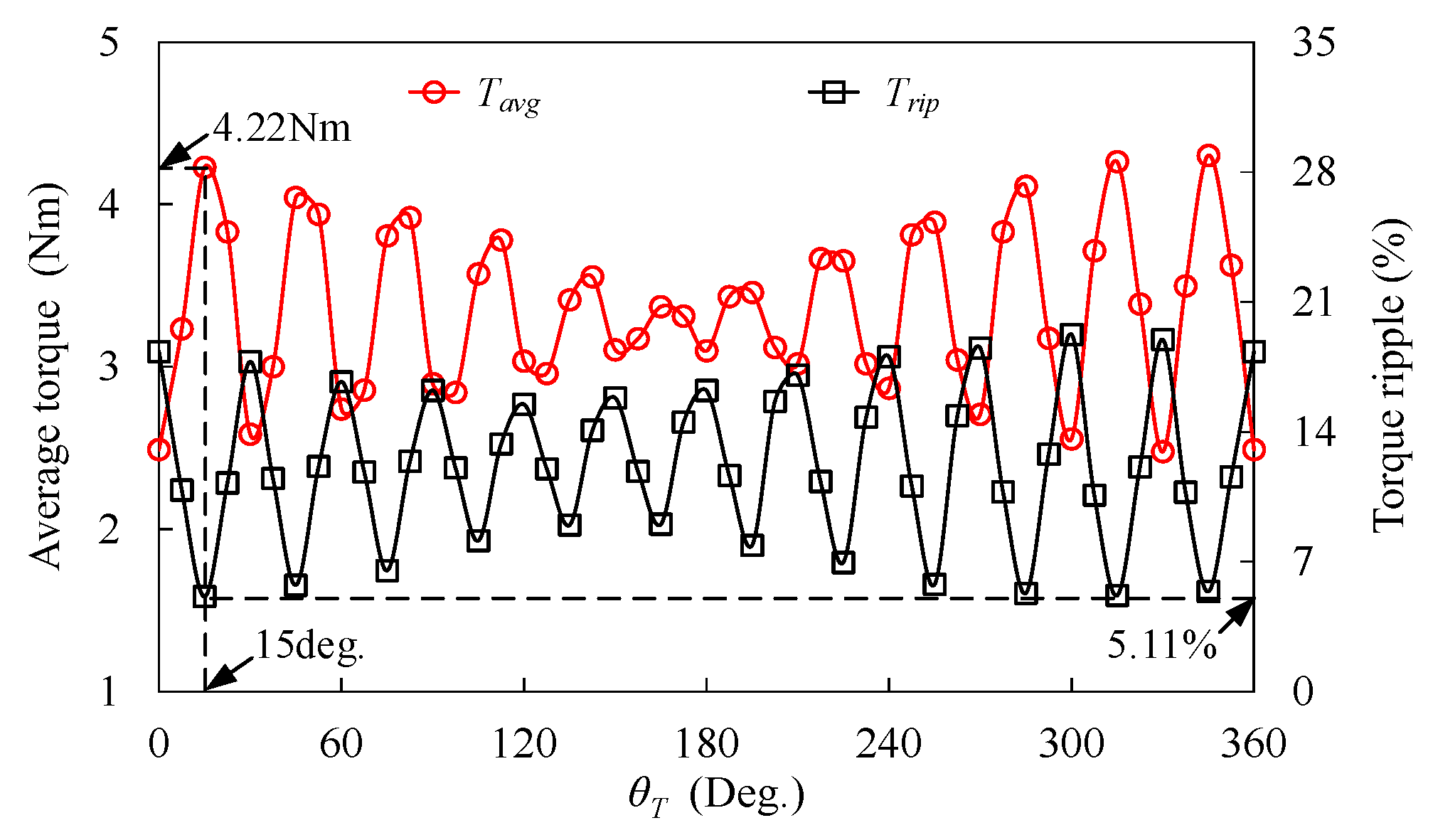
3.1. Position Relationship of Two Stators

Figure 7 shows the definition of the position between the inner and outer stator teeth (θT), and the variations of Tavg and Trip, which are depicted in Figure 8. It can be seen that the Tavg has a decreasing trend, while the Trip has an increasing trend against θT. The highest TQ can be achieved with the highest Tavg and the lowest Trip when θT = 15 deg, which means that, for MPHE-DSFRM, the outer stator tooth should be opposite to the slot between the two stator teeth of the inner stator.

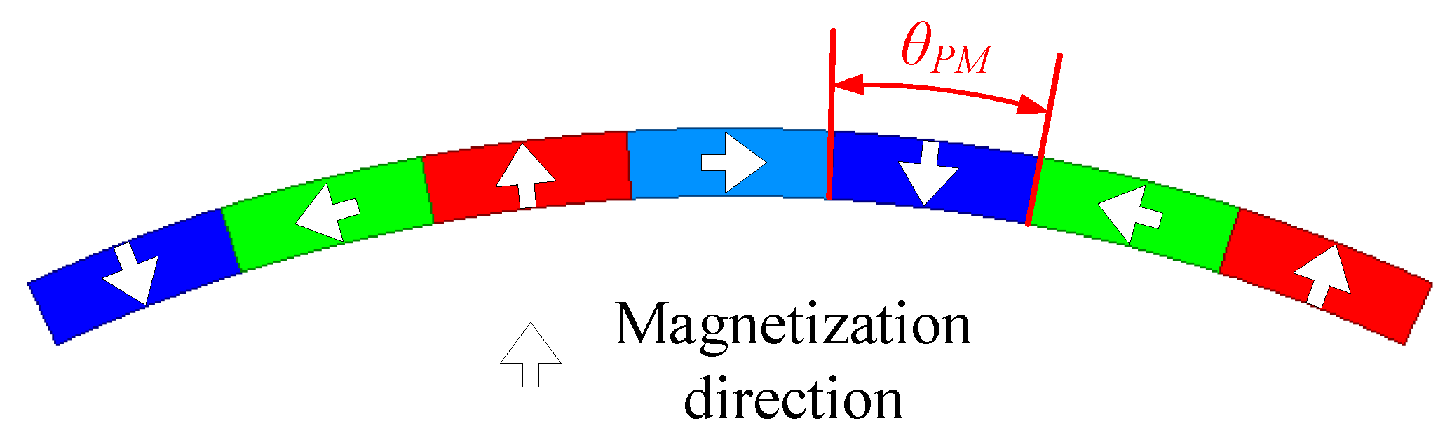
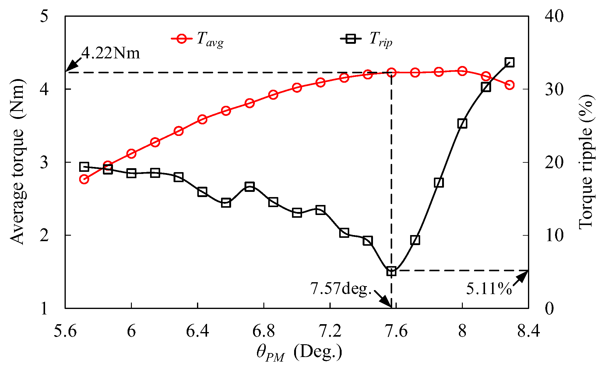
3.2. Width of Stator PM

Figure 9 shows the definition of the width of the stator PM (θPM), and the variations of Tavg and Trip against θPM are depicted in Figure 10. The Tavg increases with θPM, which means that wider PMs can achieve a higher torque value due to PMs establishing the main magnetic flux. The Trip has significant fluctuation with increasing θT, and the lowest Trip can be obtained when θPM = 7.57 deg. Considering achieving a high TQ, θPM = 7.57 deg is the optimal width of stator PM in MPHE-DSFRM.

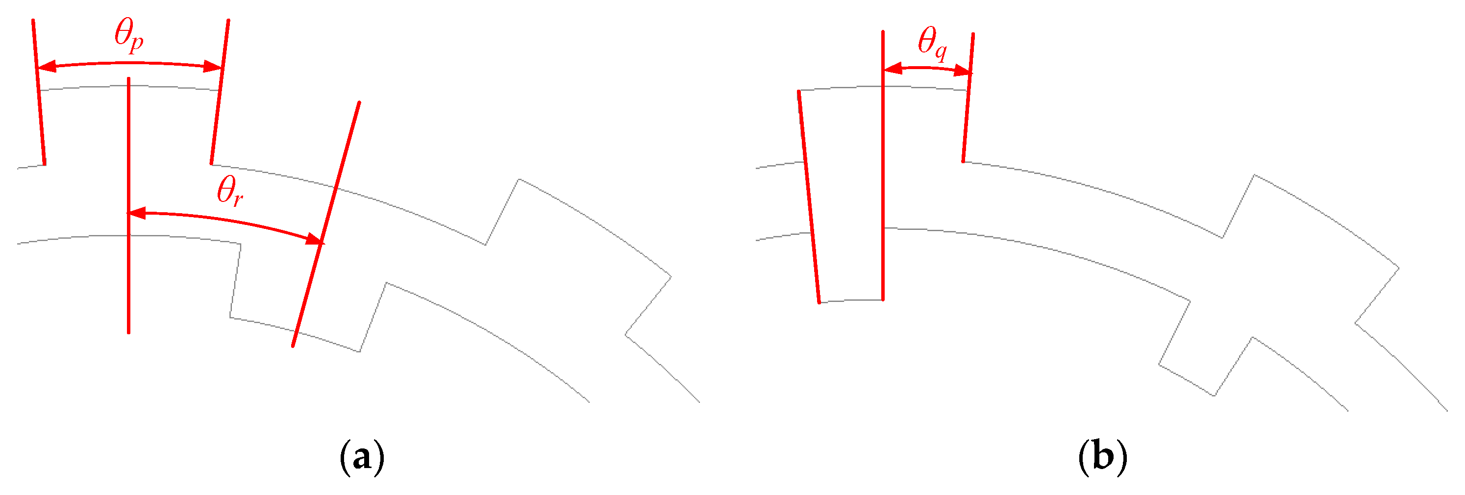
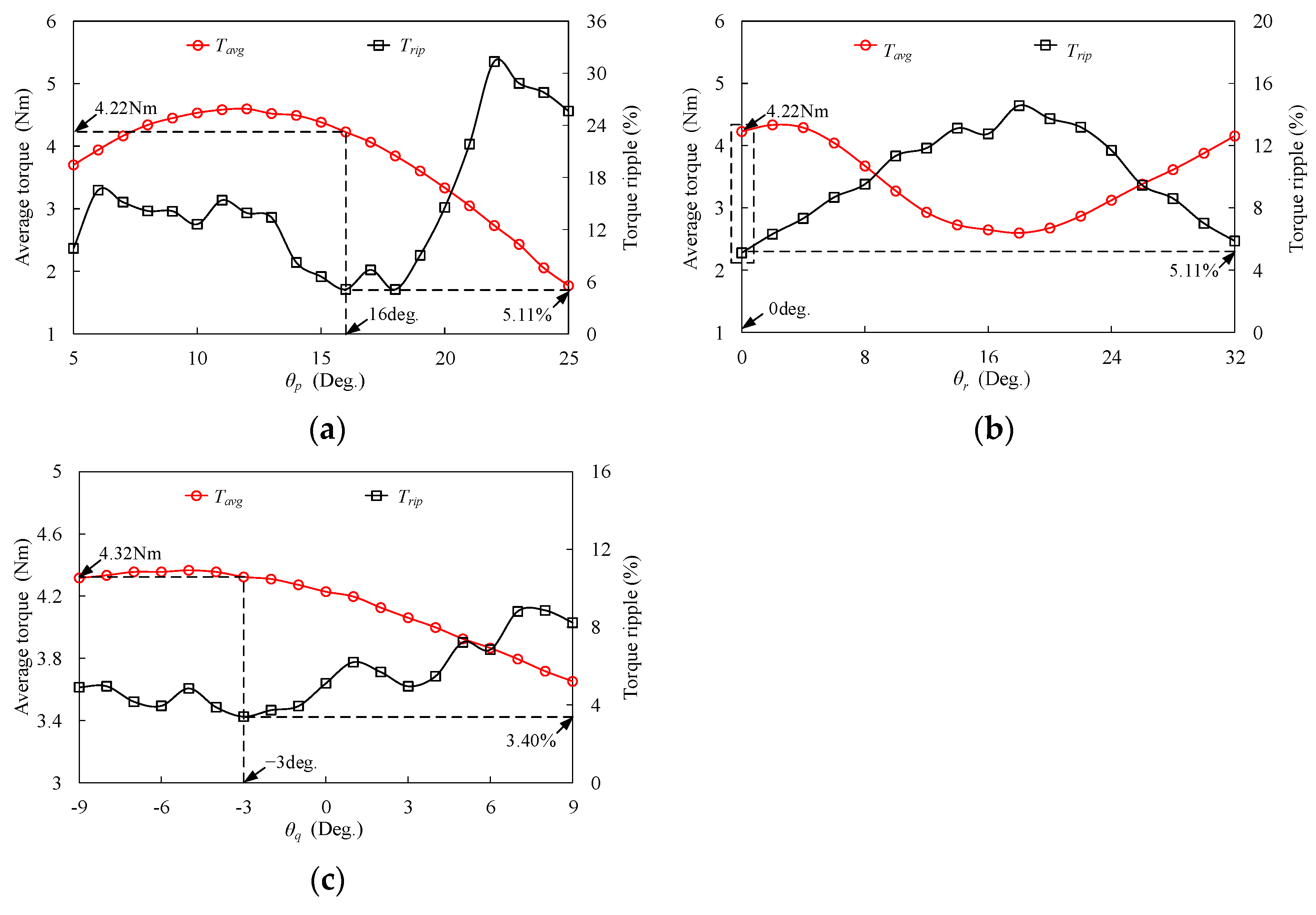
3.3. Design Parameters for Rotor

The definition of design parameters for rotor are shown in Figure 11, which includes the width of the salient pole (θp), the position between the outer and inner teeth on the rotor (θr), and the angle difference between the outer and inner teeth on the rotor (θq). The variations of Tavg and Trip for these parameters are presented in Figure 12. It can be seen that high Tavg and low Trip can be achieved when θp = 16 deg, θr = 0 deg, and θq = −3 deg. The results indicate that for MPHE-DSFRM, the outer and inner salient poles should have the same position on the rotor. Furthermore, a higher torque can be obtained when the width of the inner salient pole is smaller than that of the outer salient pole on the rotor.

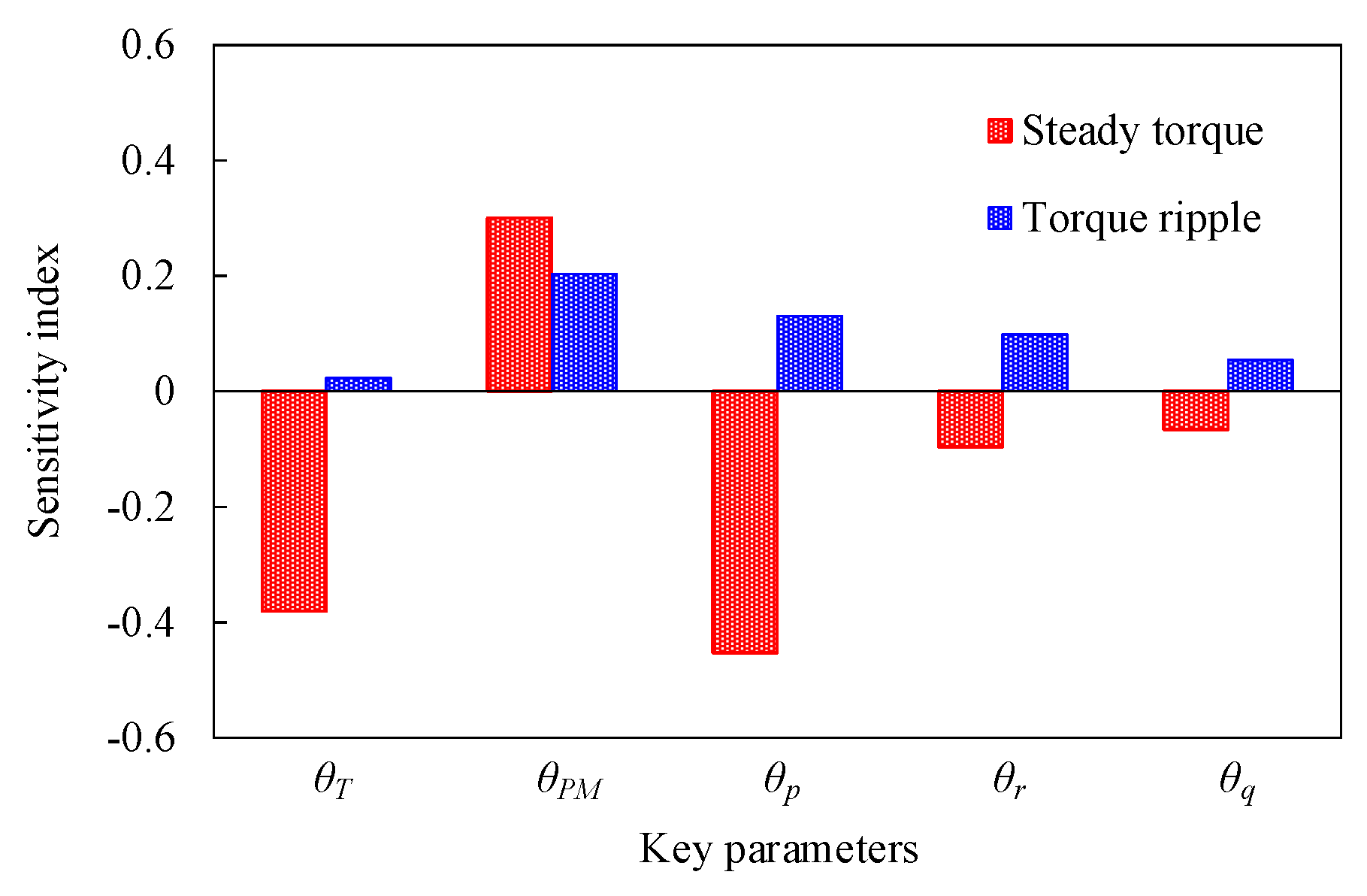
3.4. Sensitivity Analysis of Key Parameters

The key parameters have different influences on the same performance, and the same parameters have different influences on different performances. Therefore, sensitivity analysis between key parameters and optimization objectives (Tavg and Trip) is needed. The sensitivity indices of these parameters are shown in Figure 13, which can be expressed as [39]
S y i = V E y i / x i V y i
where xi and yi are the parameter and optimization objectives (Tavg and Trip), respectively. E(yi/xi) is the average value of yi. V(E(yi/xi)) and V(yi) are the variances of E(yi/xi) and yi, respectively. It can be seen that θT, θPM, and θp have significant influences on Tavg; meanwhile, θPM, θp, and θr have significant influences on Trip. In order to comprehensively analyze the impact of these parameters on both Tavg and Trip, the sensitivity judgment function is introduced as
C y i = λ 1 S a v g y i + λ 2 S r i p y i λ 1 = 0.6 ,   λ 2 = 0.4
where |Savg(yi)| and |Srip(yi)| are the absolute value of the sensitivity index of Tavg and Trip, respectively. λ1 and λ2 are the weight coefficient of |Savg(yi)| and |Srip(yi)|, respectively. The sensitivity judgments of these parameters are shown in Table 2, which shows that θT, θPM, and θp have more significant influences than θr and θq when considering both the Tavg and Trip. Therefore, θT, θPM, and θp should be given priority consideration to achieve high torque quality during the design process of the proposed MPHE-DSFRM.
Based on the optimized key parameters, MPHE-DSFRM, MPE-DSFRM, DSFRM, and conventional FRM are designed, which are simply referred to as Models I, II, III, and IV, respectively. The geometric configurations and key design parameters are shown in Figure 14 and Table 3. For a fair comparison, these four models share the same key design parameters, i.e., stack length, outer diameter of outer stators, the inner and outer airgap lengths, and PM volume.

4. Electromagnetic Performance Analysis

To show the merits of the proposed MPHE-DSFRM, the electromagnetic performances under no-load and rated state conditions are comparatively analyzed using FEA.

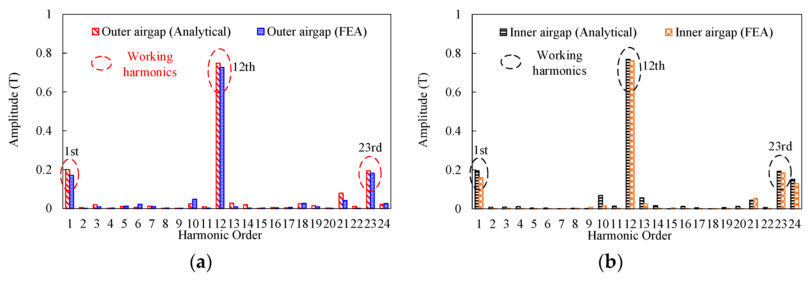
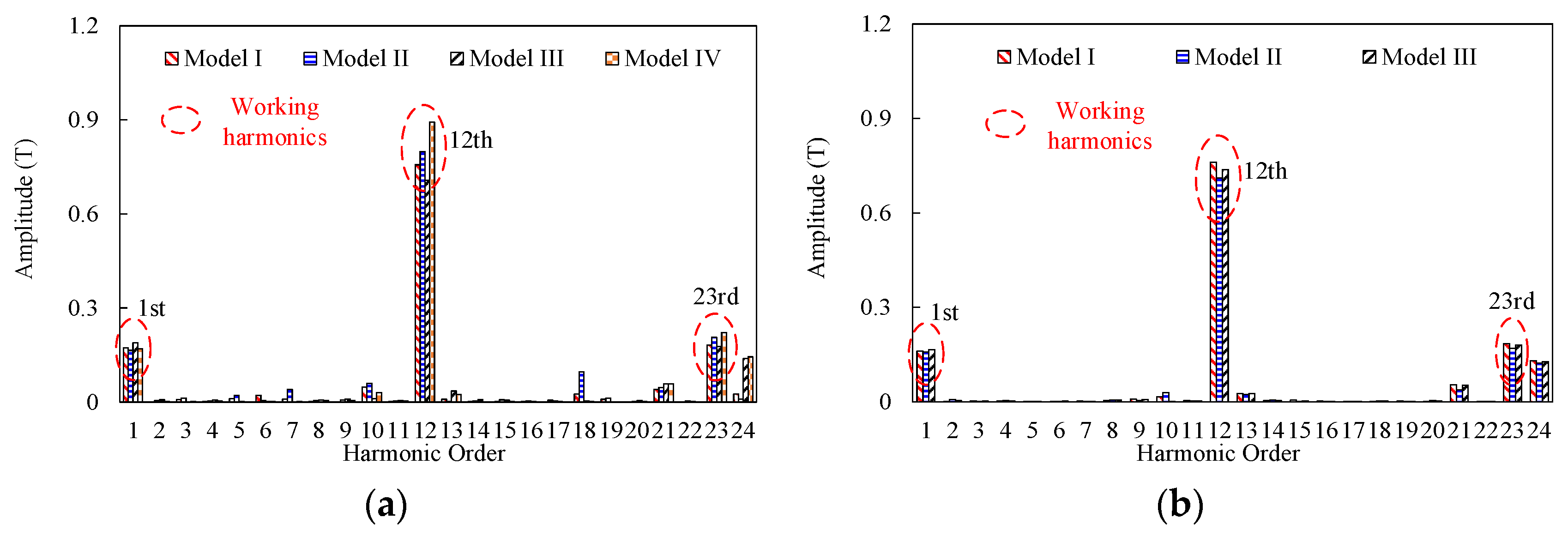
4.1. No-Load Airgap Flux Density

The airgap flux densities and corresponding harmonics spectra at the no-load state of these four investigated models are shown in Figure 15. The stators of the four models employ twelve PPNs of PM excitation, one PPN of armature reaction, and eleven rotor salient poles. According to the field modulation theory, working harmonics includes the first (n = 1, m = −1), the twelfth (n = 1, m = 0), and the twenty-third (n = 1, m = 1) order harmonic components in the airgap. The amplitudes of working harmonic components of Models I and II are higher than those of Model III. Therefore, it can be deduced that Models I and II with MPE provide a higher output of torque when compared to Model III. It should be noted that Models I, II, and III can have a higher torque output compared to Model IV, which is mainly due to the higher total airgap flux density by two airgaps. Furthermore, the amplitude of the seventh and eighteenth harmonics (useless order harmonic) of Model II are higher than those of Model I. This indicates that Model I can suppress harmonic distortion with the employment of MPHE.

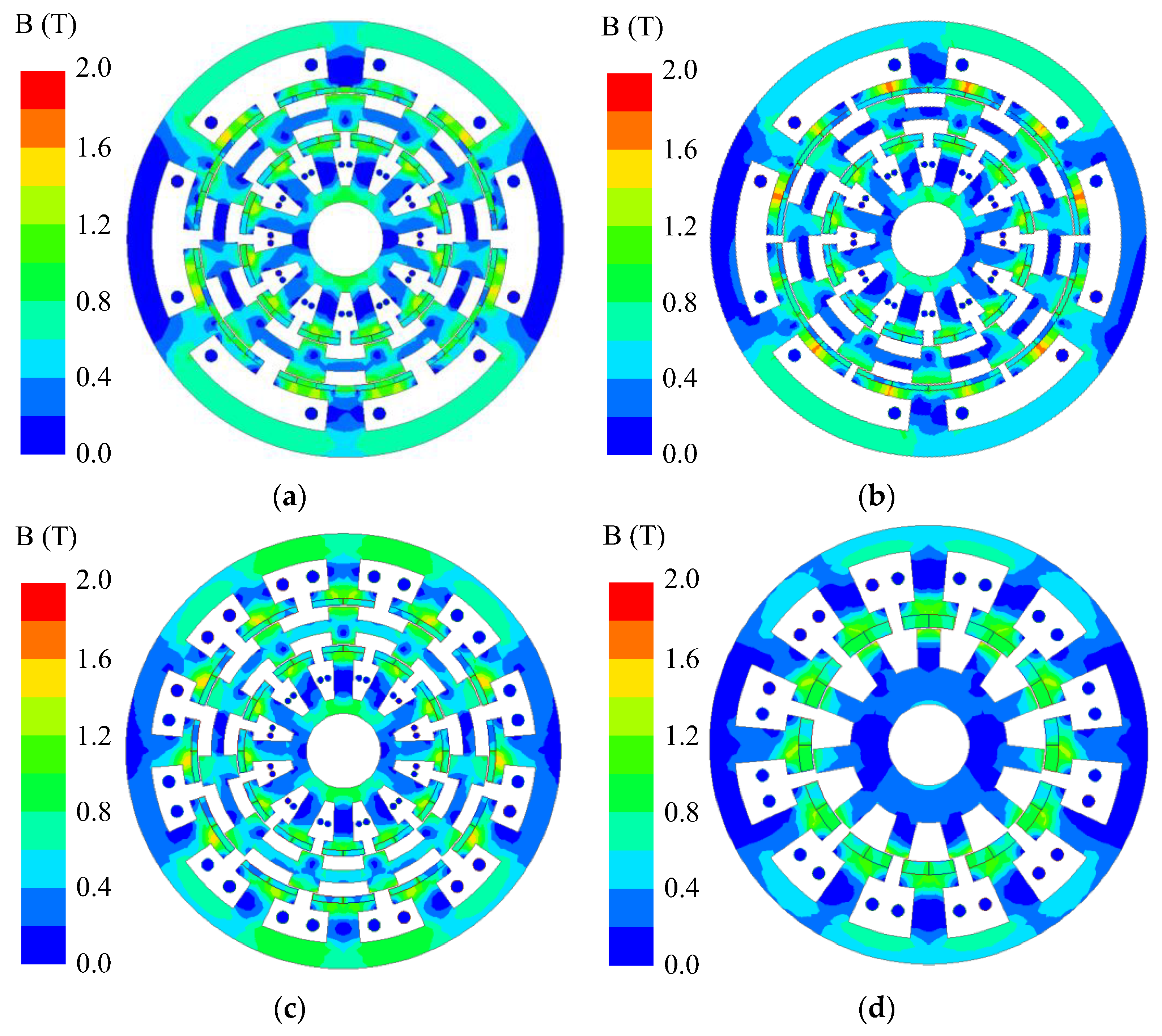
4.2. No-Load Magnetic Field Distribution

Figure 16 depicts the magnetic field distribution of four investigated models at a no-load state. It can be seen that the maximum value of flux density in these four models is 2.0 T, which is below the magnetic saturation threshold of silicon steel. The flux densities of Models I, II, and III are higher than those of Model IV, which is mainly due to the capacity for improving magnetic field distribution by dual-stator structure. The flux densities at the junction of PM and stator teeth of Model I are lower than those of Model II, which shows a higher ability by Halbach to avoid magnetic leakage. It should be noted that there are no magnetic saturation risks in these four models [13].

4.3. No-Load Back-EMF

Figure 17 depicts the waveforms and corresponding harmonic spectra of back-EMF in these four investigated models under no-load condition. From Figure 17b, Model I has the highest back-EMF fundamental amplitude in four models. The back-EMF fundamental amplitudes of Models I and II are higher than those of Models III and IV, which agree with the analysis of airgap flux density. It indicates that the back-EMF amplitude can be effectively enhanced when MPE is employed on the outer stator. The total harmonic distortion (THD) of back-EMF of Models I and II are 9.68% and 6.29%, which are higher than those of Models III and IV due to the high amplitude of the third order harmonic. The results show that the proposed MPHE-DSFRM can offer high back-EMF, but have a lower ability to suppress the THD of back-EMF compared to conventional FRM.

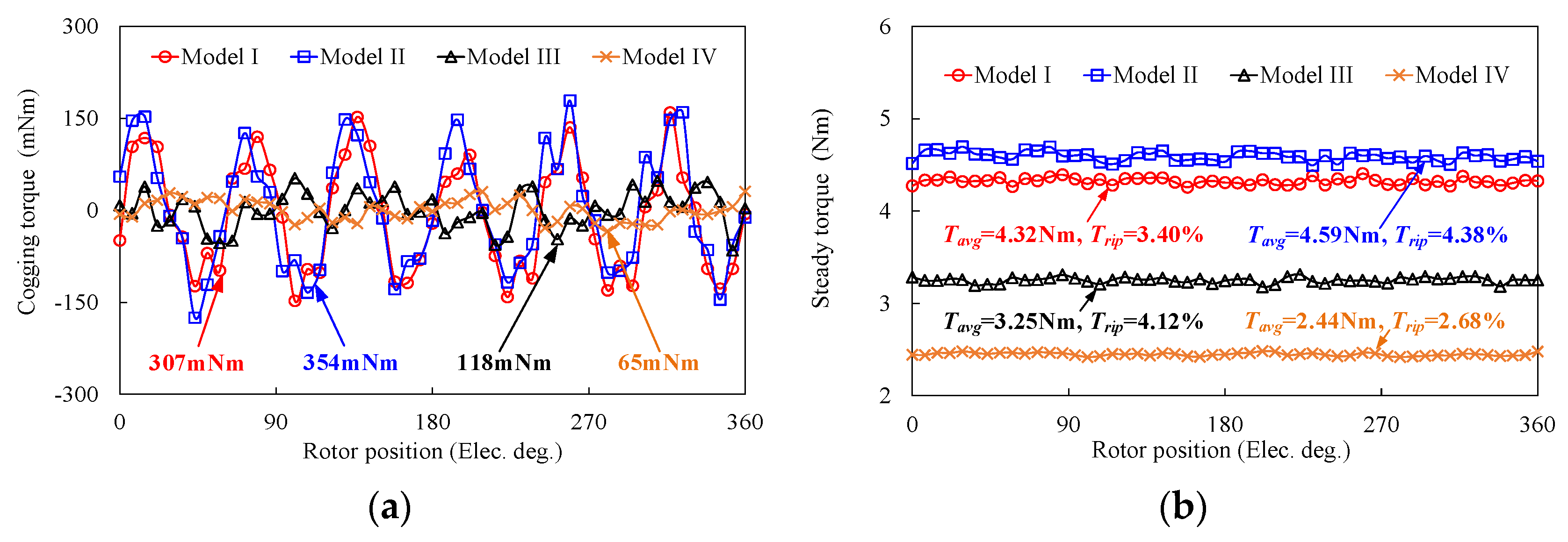
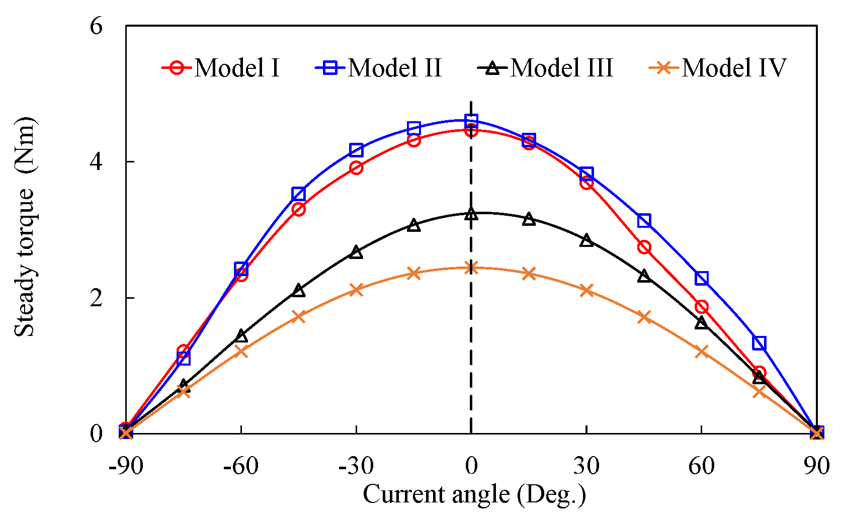
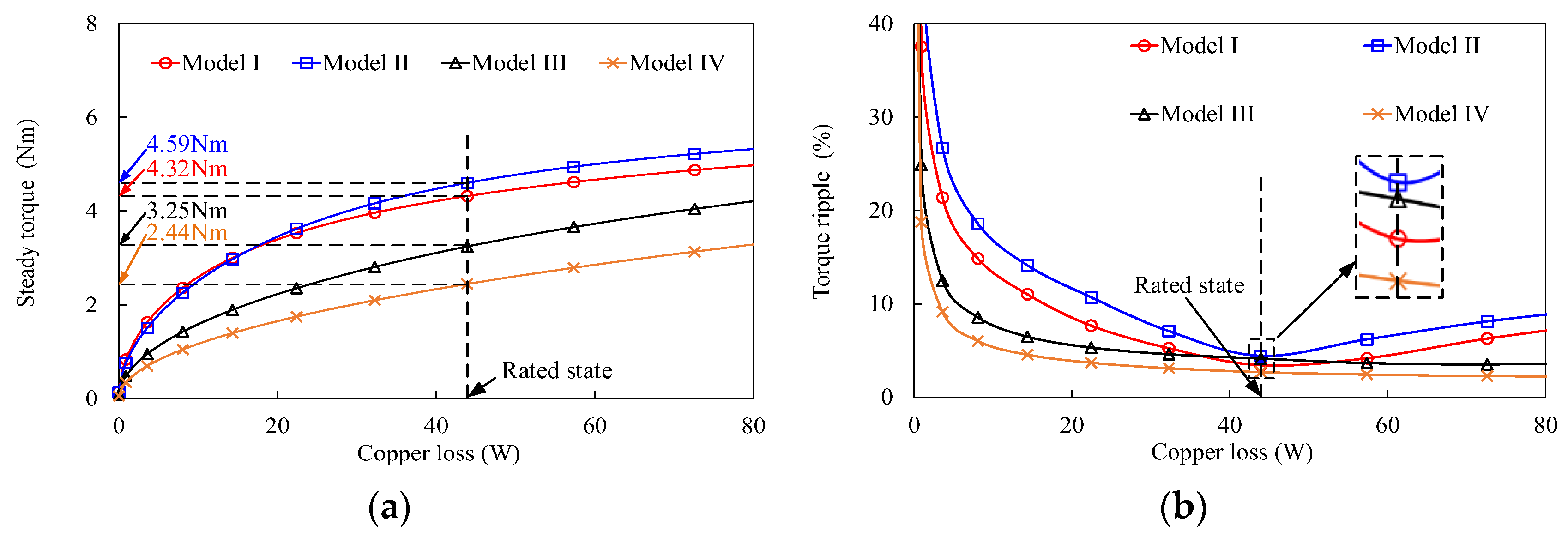
4.4. Torque Characteristics

Figure 18 shows the torque characteristics, including cogging torque and steady torque, of these four models. The peak-to-peak values of cogging torque of Models I, II, and III are higher than Model IV due to the structure of dual-stators. The cogging torque of Model I is reduced by 13.27% compared to Model II, which shows the ability of reducing the cogging torque by Halbach array. From Figure 18b, the steady torque waveforms of these four models are obtained when the rated current (2.97 Arms) is applied. The steady torques of Models I, II, and III are higher than Model IV, which verifies the merit of the dual-stator. Due to employment of MPE, the steady torque of Models I and II is increased by 32.92% and 41.23% compared to Model IV. Furthermore, the steady torque of Model I is 5.88% lower than Model II, but the torque ripple is increased by 22.37%, which is mainly attributed to the MPHE. According to a comparison of torque characteristics in Table 4, Model I can provide the highest torque quality at the rated state, which is suitable for EVs requiring high propulsive force and high stability.
Figure 19 shows the waveforms of Tavg versus the current angle on four models with the rated current applied. The maximum value of Tavg of four models can be achieved when the current angle is 0°. It indicates that an Id = 0 control can be used in the constant-torque region in the four investigated models. With the employment of dual-stator and MPE, the Tavg of Models I and II are higher than those of Models III and IV at each current angle. The steady torques and torque ripples against copper losses for these four models are shown in Figure 20. It can be seen that Models I and II have higher torque values, but higher torque ripples than Models III and IV at almost every one of the copper losses. The analysis about steady torques and torque ripples for these four models agrees with the performance analysis at the no-load state.
In order to show the advantages of MPHE-DSFRM more clearly, the electromagnetic performances of these four models are compared and listed in Table 4. The results show that the proposed MPHE-DSFRM has the merits of high torque density, high torque quality, high specific torque, and high PM utilization.

5. Conclusions

This paper proposes a high torque density of MPHE-DSFRM, which uses two pole pairs’ numbers (PPNs) of PM excitation on one outer stator tooth, and one PPN of PM excitation on one inner stator tooth. The introduction of different PPNs of PM excitation on the outer and the inner stators can optimize magnetic circuit and airgap flux density. A Halbach array is formed by inserting three pieces of circumferentially magnetized PMs into four pieces of radially magnetized permanent magnets (PMs) on the outer stator, which aims to further enhance torque density, and reduce torque ripple. The evolution process, analytical modeling, and working principle of the proposed MPHE-DSFRM are provided. The representative DSFRM and conventional FRM are established and compared to show the merits of MPHE and the dual-stator. Some important conclusions can be obtained in the design process of the proposed MPHE-DSFRM, as follows:
(1) Flux linkage and torque output can be effectively enhanced by the structure of multiple poles of PMs on each stator tooth, compared to two poles of PMs on each stator tooth.
(2) According to sensitivity analysis, the key design parameters have different levels of influence on the torque output. This is especially the case for the position between two stators, the width of PM, and the width of the salient pole; the torque value and torque ripple will have a significant change as these three parameters change.
(3) The flux densities of DSFRMs are higher than those of FRM, which is mainly due to the dual-stator structure. The proposed MPHE-DSFRM has a lower torque ripple than MPE-DSFRM due to employment of different PPNs of PM excitation with a Halbach array.
The comparison of analytical and FEA-predicted results validates the correctness and effectiveness of the theoretical analysis and the proposed design for MPHE-DSFRM. The proposed MPHE-DSFRM has the merits of high torque density, high torque quality, and high PM utilization, which is a desirable choice for the EVs’ application, requiring high propulsive force and high stability.

Author Contributions

All authors have contributed to this work. Software, S.T.; writing—original draft preparation, S.T.; writing—review and editing, Y.X. and C.H.; supervision, J.Y. All authors have read and agreed to the published version of the manuscript.

Funding

This research received no external funding.

Data Availability Statement

The data from this study are available on request from the first author, upon reasonable request.

Conflicts of Interest

The authors declare no conflicts of interest.

References

  1. Wang, D.; Peng, C.; Wang, B.; Feng, Z.; Li, J. Permanent magnet synchronous machines with nonuniformly distributed teeth. IEEE Trans. Ind. Electron. 2022, 69, 8705–8715. [Google Scholar] [CrossRef]
  2. Qiao, G.; Liu, Y.; Wang, M.; Liu, F.; Zheng, P. Study of a high-efficiency series–parallel-connected hybrid-PM variable-flux permanent magnet synchronous machine. IEEE Trans. Magn. 2022, 58, 8201207. [Google Scholar] [CrossRef]
  3. Zhao, H.; Liu, C.; Song, Z. Design of an effective double-rotor machine with robust mechanical structure. IEEE Trans. Magn. 2020, 56, 7503407. [Google Scholar] [CrossRef]
  4. Xu, X.; Chen, J.; Lin, Z.; Qiao, Y.; Chen, X.; Zhang, Y.; Xu, Y.; Li, Y. Optimization design for the planetary gear train of an electric vehicle under uncertainties. Actuators 2022, 11, 49. [Google Scholar] [CrossRef]
  5. Zhao, W.; Hu, Q.; Ji, J.; Ling, Z.; Li, Z. Torque generation mechanism of dual-permanent-magnet-excited vernier machine by air-gap field modulation theory. IEEE Trans. Ind. Electron. 2023, 70, 9799–9810. [Google Scholar] [CrossRef]
  6. Zhu, X.; Lee, C.H.T.; Chan, C.C.; Xu, L.; Zhao, W. Overview of flux-modulation machines based on flux-modulation principle: Topology, theory, and development prospects. IEEE Trans. Transp. Electrif. 2020, 6, 612–624. [Google Scholar] [CrossRef]
  7. Li, Y.; Zhou, Q.; Ding, S.; Li, W.; Hang, J. Investigation of air-gap field modulation effect in spoke-type PM machines. IEEE Trans. Transp. Electrif. 2023, 9, 845–855. [Google Scholar] [CrossRef]
  8. Wang, H.; He, C.; Xu, W.; Zhu, H.; Yang, J. Design and analysis of a new separated type permanent magnet machine based on bidirectional field modulation effect. IEEE Trans. Energy Convers. 2023, 38, 2202–2210. [Google Scholar] [CrossRef]
  9. Yang, K.; Zhao, F.; Yu, J.; Wang, Y. A novel partitioned-stator flux reversal machine with two sets of permanent magnet. IEEE Trans. Magn. 2023, 59, 8102506. [Google Scholar] [CrossRef]
  10. Gao, Y.; Kosaka, T.; Liu, Y.; Doppelbauer, M.; Qu, R. Comparative analysis of double flux modulation permanent magnet machines with different stator PM arrangements. IEEE Trans. Ind. Appl. 2022, 58, 1941–1951. [Google Scholar] [CrossRef]
  11. Gao, Y.; Doppelbauer, M.; Qu, R.; Li, D.; Ding, H. Synthesis of a flux modulation machine with permanent magnets on both stator and rotor. IEEE Trans. Ind. Appl. 2021, 57, 294–305. [Google Scholar] [CrossRef]
  12. Zhao, H.; Liu, C.; Song, Z.; Wang, W.; Lubin, T. A dual-modulator magnetic-geared machine for tidal-power generation. IEEE Trans. Magn. 2020, 56, 6703607. [Google Scholar] [CrossRef]
  13. Xu, G.; Jian, L.; Gong, W.; Zhao, W. Quantitative comparison of flux-modulated interior permanent magnet machines with distributed windings and concentrated windings. Prog. Electromagn. Res. 2012, 129, 109–123. [Google Scholar] [CrossRef]
  14. Jian, L.; Shi, Y.; Liu, C.; Xu, G.; Gong, Y.; Chan, C.C. A novel dual-permanent-magnet-excited machine for low-speed large-torque applications. IEEE Trans. Magn. 2013, 49, 2381–2384. [Google Scholar] [CrossRef]
  15. Su, P.; Wang, Y.; Li, Y.; Hua, W.; Shen, Y. Design and analysis of axial-modular flux-switching permanent magnet machine. IEEE Trans. Transp. Electrif. 2023, 9, 3649–3661. [Google Scholar] [CrossRef]
  16. Meng, Y.; Fang, S.; Pan, Z.; Liu, W.; Qin, L. Design and analysis of a new partitioned stator hybrid-excited flux reversal machine with dual-PM. IEEE Trans. Magn. 2022, 58, 8100806. [Google Scholar] [CrossRef]
  17. Yang, H.; Zhu, Z.Q.; Lin, H.; Li, H.; Lyu, S. Analysis of consequent-pole flux reversal permanent magnet machine with biased flux modulation theory. IEEE Trans. Ind. Electron. 2020, 67, 2107–2121. [Google Scholar] [CrossRef]
  18. Zahid, A.; Khan, F.; Ahmad, N.; Sami, I.; Ullah, W.; Ullah, N.; Ullah, N.; Alkhammash, H.I. Design and analysis of dual mover multi-tooth permanent magnet flux switching machine for ropeless elevator applications. Actuators 2021, 10, 81. [Google Scholar] [CrossRef]
  19. Meng, Y.; Fang, S.; Li, Y.; Zhong, Y.; Qin, L. Design and analysis of new dual-stator flux modulated machines with dual-PM excitation. IEEE Trans. Ind. Appl. 2023, 59, 1383–1393. [Google Scholar] [CrossRef]
  20. Yu, J.; Liu, C.; Liu, S.; Zhao, H. Comparative study of double-stator interior-PM vernier machines based on electromagnetic-structural coupling analysis. IEEE Trans. Ind. Electron. 2021, 68, 10510–10520. [Google Scholar] [CrossRef]
  21. Zhang, X.; Yang, H.; Li, Y.; Niu, S. Comparative study of novel dual-stator machines having different biased PM configurations. IEEE Trans. Magn. 2022, 58, 8103706. [Google Scholar] [CrossRef]
  22. Yang, H.; Lyu, S.; Zhu, Z.Q.; Lin, H.; Wang, S.; Fang, S.; Huang, Y. Novel Dual-Stator Machines With Biased Permanent Magnet Excitation. IEEE Trans. Energy Convers. 2018, 33, 2070–2080. [Google Scholar] [CrossRef]
  23. Baloch, N.; Kwon, B.-I.; Gao, Y. Low-Cost High-torque-density dual-stator consequent-pole permanent magnet vernier machine. IEEE Trans. Magn. 2018, 54, 8206105. [Google Scholar] [CrossRef]
  24. Liu, X.; Zhao, Y.; Zhu, J.; Chen, Z.; Huang, S. Multi-objective robust optimization of a dual-flux-modulator magnetic geared machine with hybrid uncertainties. IEEE Trans. Energy Convers. 2020, 35, 2106–2115. [Google Scholar] [CrossRef]
  25. Kim, D.; Hwang, H.; Bae, S.; Lee, C. Analysis and design of a double-stator flux-switching permanent magnet machine using ferrite magnet in hybrid electric vehicles. IEEE Trans. Magn. 2016, 52, 8106604. [Google Scholar] [CrossRef]
  26. Ho, S.L.; Niu, S.; Fu, W.N. A new dual-stator bidirectional-modulated pm machine and its optimization. IEEE Trans. Magn. 2014, 50, 8103404. [Google Scholar] [CrossRef]
  27. Ding, Z.; He, C.; Feng, C.; Yang, J. A new dual stator permanent magnet machine based on field modulation theory. Sustainability 2023, 15, 281. [Google Scholar] [CrossRef]
  28. Meng, Y.; Fang, S.; Zhu, Y.; Yu, Y.; Qin, L. Investigation of new dual-stator consequent-pole flux reversal permanent magnet arc machines. IEEE Trans. Appl. Superconduct. 2024, 1–5. [Google Scholar] [CrossRef]
  29. Wang, H.; Fang, S.; Lu, X.; Ni, H.; Yang, H.; Lin, H. Analysis of a new dual-stator vernier machine with hybrid magnet flux-reversal arrangement. IEEE Trans. Appl. Superconduct. 2019, 29, 0600805. [Google Scholar] [CrossRef]
  30. Pan, Z.; Fang, S.; Lin, H.; Yang, H.; Xue, S. A new double-sided flux reversal arc permanent magnet machine with enhanced torque density capability. IEEE Trans. Magn. 2019, 55, 8102506. [Google Scholar] [CrossRef]
  31. Meng, Y.; Fang, S.; Wang, H.; Pan, Z.; Qin, L. Design and analysis of a new dual-stator consequent-pole flux reversal machine with triple-PM excitation. IEEE Trans. Magn. 2021, 57, 8105904. [Google Scholar] [CrossRef]
  32. Kwon, J.-W.; Kwon, B.-I. High-efficiency dual output stator-PM machine for the two-mode operation of washing machines. IEEE Trans. Energy Convers. 2018, 33, 2050–2059. [Google Scholar] [CrossRef]
  33. Yu, J.; Liu, C.; Zhao, H. Design and optimization procedure of a mechanical-offset complementary-stator flux-reversal permanent-magnet machine. IEEE Trans. Magn. 2019, 55, 8204007. [Google Scholar] [CrossRef]
  34. Wei, L.; Nakamura, T. A novel dual-stator hybrid excited permanent magnet vernier machine with Halbach-array PMs. IEEE Trans. Magn. 2021, 57, 8101705. [Google Scholar] [CrossRef]
  35. Shi, Y.; Jian, L. A novel dual-permanent-magnet-excited machine with flux strengthening effect for low-speed large-torque applications. Energies 2018, 11, 153. [Google Scholar] [CrossRef]
  36. Cao, L.; Zhou, Y.; Yang, G.; He, Y.; Xie, S.; Lee, C.H.T. Decoupling analysis of brushless dual-mechanical-port dual- electrical-port machines. IEEE Trans. Ind. Electron. 2024, 71, 4361–4374. [Google Scholar] [CrossRef]
  37. Wang, H.; Xu, W.; Xu, Y.; He, C. Design and analysis of permanent magnet machines with multiple arc pole ratios in stator teeth. IEEE Trans. Energy Convers. 2024, 39, 1278–1287. [Google Scholar] [CrossRef]
  38. Jian, L.; Deng, Z.; Shi, Y.; Wei, J.; Chan, C.C. The mechanism how coaxial magnetic gear transmits magnetic torques between its two rotors: Detailed analysis of torque distribution on modulating ring. IEEE/ASME Trans. Mechatron. 2019, 24, 763–773. [Google Scholar] [CrossRef]
  39. Ma, C.; Qu, L. Multiobjective optimization of switched reluctance motors based on design of experiments and particle swarm optimization. IEEE Trans. Energy Convers. 2015, 30, 1144–1153. [Google Scholar] [CrossRef]
Figure 1. The topology of the proposed MPHE-DSFRM.
Actuators 13 00275 g001
Figure 2. Topology of FRM with different poles of PMs on one stator tooth.
Actuators 13 00275 g002
Figure 3. Comparison of FRM with different poles of PMs on one stator tooth. (a) Flux linkage waveforms. (b) Steady torque waveforms.
Actuators 13 00275 g003
Figure 4. Trend of amplitude of flux linkage following different rotor pole numbers.
Actuators 13 00275 g004
Figure 5. Evolution process of the proposed MPHE-DSFRM from FRM.
Actuators 13 00275 g005
Figure 6. The harmonics distributions of airgap flux density of the proposed MPHE-DSFRM. (a) Outer airgap. (b) Inner airgap.
Actuators 13 00275 g006
Figure 7. Definition of the position relationship of two stators in MPHE-DSFRM.
Actuators 13 00275 g007
Figure 8. Variations of Tavg and Trip to θT.
Actuators 13 00275 g008
Figure 9. Definition of the PM width in the proposed MPHE-DSFRM.
Actuators 13 00275 g009
Figure 10. Variation of Tavg and Trip to θPM.
Actuators 13 00275 g010
Figure 11. Definition of design parameters for the rotor. (a) θp and θr. (b) θq.
Actuators 13 00275 g011
Figure 12. Variation of Tavg and Trip to parameters. (a) θp. (b) θr. (c) θq.
Actuators 13 00275 g012
Figure 13. Sensitivity analysis of optimization objectives Tavg and Trip.
Actuators 13 00275 g013
Figure 14. Geometric configurations of investigated models.
Actuators 13 00275 g014
Figure 15. Harmonic spectra of airgap flux density at no-load state. (a) Outer airgap. (b) Inner airgap.
Actuators 13 00275 g015
Figure 16. No-load magnetic field distribution. (a) Model I. (b) Model II. (c) Model III. (d) Model IV.
Actuators 13 00275 g016
Figure 17. Comparison of back-EMFs of four models at no-load state. (a) Back-EMF waveforms. (b) Corresponding harmonic spectra.
Actuators 13 00275 g017
Figure 18. Comparison of torque characteristics of four investigated models. (a) Cogging torque at no-load. (b) Steady torque at rated state.
Actuators 13 00275 g018
Figure 19. Average torque amplitudes versus current angle of four investigated models.
Actuators 13 00275 g019
Figure 20. The torque characteristics against copper losses. (a) Average torque value. (b) Torque ripple.
Actuators 13 00275 g020
Table 1. Comparison of amplitude of the back-EMF and flux linkage in FRM of six and twelve slots with different rotors.
NsNrPPNkdkpkwUb (V)ψf (10−2 Wb)NsNrPPNkdkpkwUb (V)ψf (10−2 Wb)
64810.8660.8665.271.591216810.8660.8661.550.68
5710.50.510.511.8517710.9330.9332.340.77
7510.50.51.520.9719510.9330.9333.511.12
8410.8660.8667.032.2120410.8660.8664.131.33
10210.8660.8666.684.1822210.50.54.951.59
11110.50.514.794.7123110.50.55.071.62
13110.50.514.204.5625110.50.54.771.53
14210.8660.8666.123.8326210.50.54.711.50
16410.8660.8664.981.6828410.8660.8663.891.24
17510.50.51.200.7129510.9330.9333.281.06
19710.50.50.940.2931710.9330.9332.170.71
20810.8660.8660.910.2632810.8660.8661.670.53
Table 2. Comparison of sensitivity of key design parameters.
ItemsS(yi)C(yi)Sensitivity
SavgSrip
θT−0.380.020.24
θPM0.300.210.26
θp−0.450.130.32
θr−0.090.100.09×
θq−0.070.050.06×
√ Strong sensitive parameter; × Weak sensitive parameter.
Table 3. Key design parameters of four models.
ItemsModel IModel IIModel IIIModel IV
Outer/inner pole number of PM4/24/22/22/-
Outer/inner stator slot number6/126/1212/1212/-
Outer/inner diameter of outer stator (mm)140/97.62140/97.37140/98140/83
Outer/inner diameter of inner stator (mm)64/24-
Outer/inner diameter of rotor (mm)93/6973.8/26
Active length of outer/inner airgap (mm)0.5/0.50.5/-
PPN of rotor11
Active stack length (mm)20
PPN of the outer/inner PM12/1212/-
PPN of the outer/inner armature reaction1/11/-
PM volume (cm3)16.26
PM gradeN38SH
Rated speed (rpm)273
RMS value of rated current (Arms)2.97
Current density at rated state (A/mm2)5.35
θT (deg.)15150-
Outer/inner θPM (deg.)7.57/1214.25/1212/1212/-
θr (deg.)16161212
θp (deg.)000-
θq (deg.)−3−60-
Table 4. Electromagnetic performances of investigated models.
ItemsModel IModel IIModel IIIModel IV
Amplitude of back-EMF (V)26.5124.9314.8711.06
THD of back-EMF (%)9.686.291.062.02
Peak-to-peak cogging torque (mNm)30735411865
Steady torque at rated state (Nm)4.324.593.252.44
Torque ripple (%)3.404.384.122.68
Torque quality, TQ1.271.050.790.91
Machine volume (cm3)307.87
Machine weight (kg)2.42
Torque density (×10−2 Nm/cm3)1.401.491.050.79
Specific torque (Nm/kg)1.781.891.341.01
Torque per PM volume (Nm/cm3)0.2650.2820.1990.150
Disclaimer/Publisher’s Note: The statements, opinions and data contained in all publications are solely those of the individual author(s) and contributor(s) and not of MDPI and/or the editor(s). MDPI and/or the editor(s) disclaim responsibility for any injury to people or property resulting from any ideas, methods, instructions or products referred to in the content.

