Article

Design and Implementation of Bulk Feeders Using Voice Coil Motors

1
Department of Electrical and Computer Engineering, Tamkang University, New Taipei City 25137, Taiwan
2
CT Green Tech Co., Ltd., No. 280, Sec. 3, Dadu Rd., Beitou Dist., Taipei City 11259, Taiwan
3
Puton Technology Inc., 2F-15, No. 12, Ln.609, Sec. 5, Chongxin Rd., Sanchong Dist., New Taipei City 24159, Taiwan
*
Author to whom correspondence should be addressed.
Actuators 2024, 13(8), 281; https://doi.org/10.3390/act13080281
Submission received: 7 May 2024 / Revised: 20 July 2024 / Accepted: 22 July 2024 / Published: 26 July 2024

Abstract

:
Bulk feeders that can automatically feed materials are one of the most commonly used vibration devices in the electronics industry. This study uses voice coil motors to design and implement a dual-axis bulk feeder and a quad-axis bulk feeder, allowing them to handle many kinds of materials. The implemented feeders can improve some of the problems in traditional bulk feeders, such as only one direction of movement, can only handle one kind of material, the contact time between the material and the platform is too long, and the feeder is not suitable to process materials with particular shapes. Two or four voice coil motors are placed under the platform of the implemented feeder. The vibration of the platform is controlled by the up-and-down movements of the voice coil motors, so that the bulk materials on the platform can be moved to the desired direction according to the feeding requirements. This study proposes a control method to control voice coil motors. For example, using different combinations of up-and-down movements of these four voice coil motors, the quad-axis voice coil feeder can move the material in eight horizontal directions, such as up, down, right, left, up right, up left, down right, and down left, as well as vertically flip. Since the frequency and amplitude of each vibration of the voice coil motor can be easily and instantly adjusted through the program, the implemented feeder can handle other types of materials without modifying the hardware of the device. Finally, some experimental results illustrate that the implemented dual-axis and quad-axis voice coil feeders can indeed effectively handle various bulk materials.

1. Introduction

Processing bulk solid materials has always been a primary issue in production equipment projects. Practical equipment can significantly reduce labor and replacement costs and enhance production efficiency. These devices have a wide range of applications and have been used for years in storage, movement, and processing of raw materials. Over time, the development of conveyor belts has continuously evolved, with changes in control systems, materials, and modular designs [1]. These advancements have added various functions to the conveyor belt, beyond just moving items, to enhance the efficiency of product processing. We refer to these as material alignment and feeding equipment.
Azhar and Shah [2] discussed the application of vibratory feeders in industrial automation, particularly in terms of efficiency in guiding materials. Vibratory bowl feeders are efficient and cost-effective machines, but the main disadvantage of traditional vibratory bowl feeders is their low adaptability to the shapes and orientations of materials, which is a significant limitation for the varied needs of the industry. This study proposes the installation of cameras on the feeders to analyze the orientation of the fed parts and compare it with the three-dimensional model input into the system to determine the direction in which the parts need to be rotated. This enhances flexibility and adaptability. However, the use of 3D cameras still presents problems of high costs and slower recognition speed.
Haugaard et al. [3] developed a visual method to determine incorrectly oriented parts, significantly reducing image recognition time by decreasing the size of the input image. A solution combining traditional vibratory feeders with visual sensing technology aims to enhance automation levels in low-volume, high-variability assembly tasks. By using dynamic simulation to infer possible part orientations and employing convolutional neural networks trained on synthetic data to detect and classify the stable poses of parts. Inference based on synthetic images is used to identify which stable poses the network can distinguish, and for a given configuration, this knowledge is expressed as a stochastic state transition matrix, forming the basis of a simulation-based feeder design framework. However, the flexibility of existing vision traps is limited in practice, as expert intervention is required to identify feasible tasks and configure the vision system.
Although the structure of voice coil actuators is simple, integrating suitable PWM control strategies can significantly enhance the precision and adaptability of the equipment. Kowol et al. [4] successfully implemented these actuators in a pipe organ, analyzing both open-loop and closed-loop control strategies for VCM actuators. Their proposed control strategies successfully replicated the mechanical action behavior, largely demonstrating the reliability of voice coil actuators in precision control.
As the demand for smaller-sized materials increases with the development of compact devices, feeders also need to meet specifications for small size, multivariable control, and high precision to align with current market demands. Chen et al. [5] presented a macro–micro dual-drive positioning system that demonstrated the successful use of voice coil actuators to reduce device size and friction loss. The precise control capabilities make voice coil actuators an ideal foundation for developing efficient and flexible small-scale bulk material feeders.
Building on these advancements, this study utilizes voice coil actuators as the primary drive control for bulk feeders, designing a system capable of adjusting vibration amplitude based on different materials. This design significantly reduces the waste of resetting the feeding track and minimizes the time required for material changeover, thereby increasing operational efficiency. Additionally, by controlling the PWM duty cycle and current direction of the voice coil actuators, this study extends Shewal et al.’s [6] research to offer multidirectional movement capabilities. This allows bulk materials to move up, down, left, and right, enabling both concentrated and dispersed applications, thus providing more diverse development opportunities for feeders.
The rest of this study is organized as follows: Section 2 provides a detailed introduction to the system structure of the bulk feeders. Section 3 explores the control of voice coil actuators and the motion control of the dual-axis and quad-axis voice coil feeders. Section 4 presents the performance of the voice coil feeders through experimental results. Section 5 presents the conclusion.

2. Structure of Bulk Feeder

In this study, we focus on bulk feeders suitable for handling small materials, such as screws, washers, or probes. Given the diminutive volume of these solid materials, the primary functionality has evolved from mere transportation to organizing and positioning the materials into an optimal state for processing. As illustrated in Figure 1, there are two types of bulk feeders for small materials. Figure 1a depicts a feeder requiring a dedicated jig plate placed atop the feeder, with materials scattered across the plate. This jig plate contains numerous holes, and the materials are organized into these holes through vibration. Figure 1b features a dedicated bowl-shaped material tray on top, which enhances the directional functionality of the feeder, thereby facilitating smoother subsequent operations on the production line.

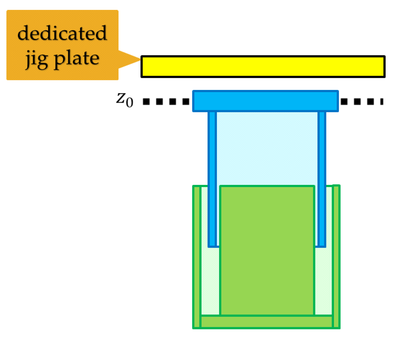
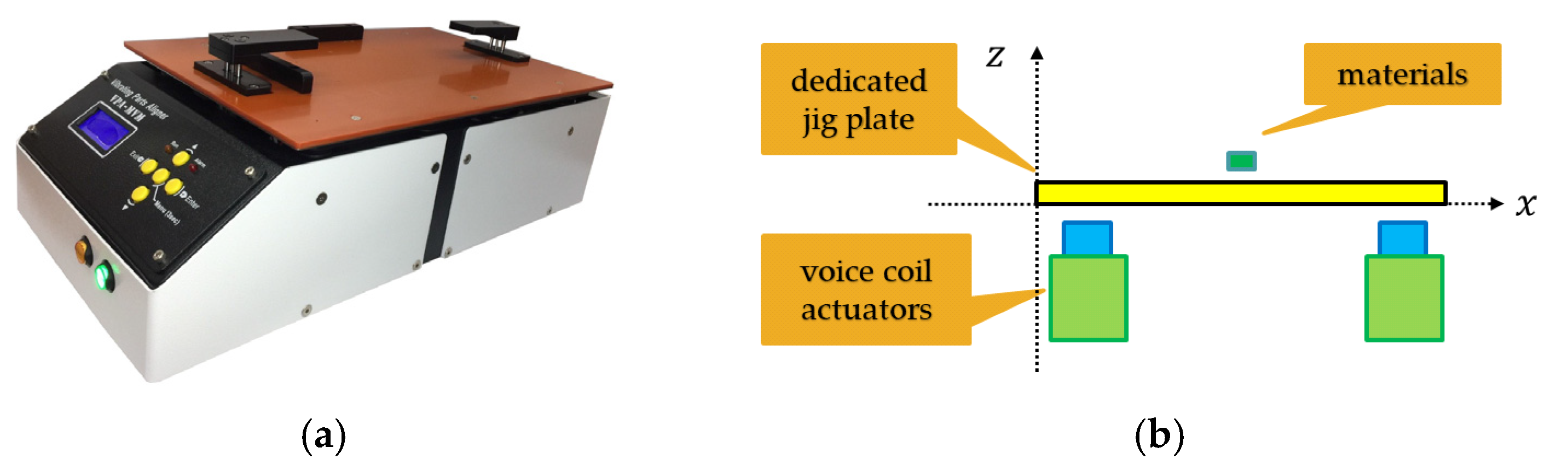
2.1. Dedicated Jig Plate Bulk Feeder

Compared to other equipment, dedicated jig plate bulk feeders possess unique advantages. Firstly, they feature offline functionality, allowing them to operate independently without being constrained by the production line speed. Secondly, the design of the jig plate area enables the simultaneous processing of many materials, enhancing production efficiency. Generally, a feeder includes two main components: (i) platform and (ii) power source. They are described as follows:
(i)
Platform:
The design of the platform is usually rectangular, allowing the jig plate to be fixed on top and filled with materials. This design ensures the stability and accuracy of the materials during the sorting process. The power source, which generates vibrations to precisely drop the materials into the holes, is connected below the platform. When designing the platform, engineers must also consider the stability of the feeder and the ease of operation, as the operator needs to be able to easily fix the jig plate or other fixtures on top, and accidents should not occur during the aligning process.
(ii)
Power source:
The power source is a crucial component that drives the operation of the feeder machine. Typically, the power source mainly utilizes a cam-type structure (Figure 2). Cam-type feeders have the advantages of simple structure, ease of operation, and low maintenance costs [7,8]. However, they also have some disadvantages, such as:
(a)
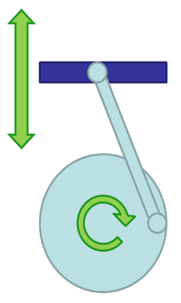
Shorter lifespan of contact-type power sources: One major drawback of cam-type feeder machines is their contact-type cam structure. Due to the contact friction between the connecting rod and the cam, mechanical parts are prone to wear out from long-term operation, which can significantly affect the lifespan of the overall mechanical structure. Wear issues may require more frequent maintenance and replacement of parts, increasing maintenance costs and reducing the reliability of the feeder.
(b)
Difficulty in adjusting vibration frequency: Vibration frequency refers to the number of times the platform oscillates up and down per second. The faster the vibration frequency, the quicker the aligning speed, and the higher the production efficiency. However, too fast a frequency can led to stacking, squeezing, and jamming of materials. When setting the vibration frequency of the feeder, factors such as the shape, size, and weight of the materials need to be considered. The vibration frequency of a cam type is determined by the motor’s speed, with most motors having a maximum speed of about 50 revolutions per second, meaning the platform’s vibration frequency can reach up to 50 Hz. Therefore, it is difficult to increase the vibration frequency of cam-type feeders.
(c)
Difficulty in adjusting amplitude: Amplitude refers to the magnitude of the platform’s vertical vibrations, generally controlled by adjusting the angle between the cam and the connecting rod and the length of the connecting rod. Adjusting the amplitude can affect the aligning effect of the machine. If the amplitude is too small, materials may not successfully enter the holes; if the amplitude is too large, it may cause instability, cracking, or damage to the materials. The amplitude of cam-type feeders is usually fixed by the structure of the cam and connecting rod, making it difficult to adjust flexibly.
(d)
Fixed vibration direction: Due to structural issues, cam-type feeders have a fixed vibration direction. This often leads to materials being vibrated to a certain area and not dispersing, requiring manual intervention.
Although cam-type feeders perform well in certain applications, their inherent disadvantages limit their applicability in more complex or diverse production requirements. With technological advancements, to keep up with the demands of modern factories, feeders also need further improvements to enhance efficiency and meet the ever-changing challenges. This study proposes a designed and implemented technique for feeders, specifically increasing the efficiency of material organization in production and being applicable to various raw materials, reducing the time and hardware costs associated with changing materials.

2.2. Bulk Feeders

Generally, most bulk feeders are devices with a bowl-like appearance, as shown in Figure 3a, with a track that circles around the inner wall of the bowl. When the feeder is activated, a strong magnetic force from an electromagnet attracts the iron piece to the platform, as shown in Figure 3b ((1) platform, (2) electromagnet, (3) iron piece). Then, by releasing the magnetic force of the electromagnet and relying on the resilience of the iron piece to bounce back (also as Figure 3c), vibration is generated. The entire bowl-shaped platform will continue to rotate and vibrate slightly, causing the materials inside to gradually move above the track with the movement inside the bowl, then slowly move up along the track, and finally reach the edge of the bowl, which is the material outlet. General bulk feeders face several issues:
(a)
Single-direction, single-material limitation: Each type of material requires a corresponding feeder, and the direction of the outlet cannot be changed. This means that when the variety of products changes, the feeder needs to be replaced or readjusted, increasing the cost and time for production-line transitions.
(b)
Issue of material friction: Inevitably, friction occurs between materials during their movement inside the bowl, especially when materials move along the track over long distances. This friction can lead to wear and damage of the materials, particularly for small, fragile items. This may render the feeding method unsuitable for some products that require high protection, such as small camera lenses for mobile phones.
(c)
Not suitable for products with special shapes or appearance requirements: The design of traditional bulk feeders tends towards simplicity and efficiency, which makes them perform relatively poorly when dealing with products of special shapes or with appearance requirements. Specially shaped materials, such as O-rings or small suction cups, may have difficulty adapting to the traditional vibratory feeding method. At the same time, the fixed position of the outlet may cause some larger-shaped materials to have difficulty flowing out, requiring additional manual handling. This may be seen as a drawback in a modern production environment that seeks automation and high efficiency.
(d)
The bowl bulk feeder, a vibratory system designed for consistent and repeatable positioning of parts, relies on its mechanical configuration to sort and orient materials effectively. While these feeders are ideal for parts with a distinct center of mass, their design limits flexibility in handling symmetrical shapes or parts requiring specific orientation features. Traditional bowl feeders face challenges, such as single-direction functionality, material-specific design requirements, and wear from friction during long track movements, which can damage delicate components. Furthermore, their inability to adapt to specially shaped products or meet appearance specifications highlights a need in feeder technology. Advancements are required to overcome these limitations, ensuring feeders can support diverse manufacturing environments and adapt to the changing demands of modern production lines.

3. Design and Implementation of Multi-Axis Voice Coil Feeder

For vibrating feeders, common power sources are divided into three main types: (a) vertical up-and-down motion, (b) left-and-right horizontal motion, and (c) front-and-back swinging motion. The choice of these motion principles depends on factors, such as the shape, size, weight, and material of the items. For example, vertical up-and-down motion is generally more suitable for elongated items, which need to be vibrated upwards away from the jig plate so that they fall precisely into the holes on the jig plate. For flat items, left-and-right horizontal motion combined with front-and-back swinging motion is more appropriate for alignment, as flat items usually do not need to be flipped and can simply slide horizontally into the holes. Due to the shorter height of flat items and shallower holes in the jig plate, horizontal motion can also prevent items in the holes from being vibrated out again. Different brands of feeder may have different power source designs, with some brands providing higher power output to handle larger objects, while others are more energy-efficient, reducing energy costs. The power source of the feeder also requires proper maintenance to ensure stable operation and efficient production.
In a study [9], the application of voice coil motors (VCMs) in precision actuation systems was explored, emphasizing their role in enhancing motion resolution and reducing hysteresis nonlinearity in positioning stages. The researchers developed a displacement reduction mechanism, specifically leveraging the capabilities of VCMs to achieve high precision and dynamic response. This approach demonstrates how voice coil motors can be effectively utilized in micro-displacement and nano-displacement environments, offering substantial improvements over traditional systems in terms of precision and efficiency. This work underlines the significant potential of VCMs in critical applications requiring exact control and minimal mechanical interference [9].
This study proposes a designed and implemented method of bulk feeders that utilizes voice coil actuators as the vibration power sources. Through its high-speed reciprocating effects and various combinations, it achieves the purpose of multidirectional vibration feeding. This study’s proposed feeder corrects the drawbacks of traditional contact vibration feeders, such as the inability to adjust amplitude through software, a lower-frequency limit, making it difficult to align small items, and the capability to handle items that traditional feeders cannot. This section will delve into the principles of the voice coil actuator used in the feeder and a device capable of adjusting movement speed and position through various signal methods.

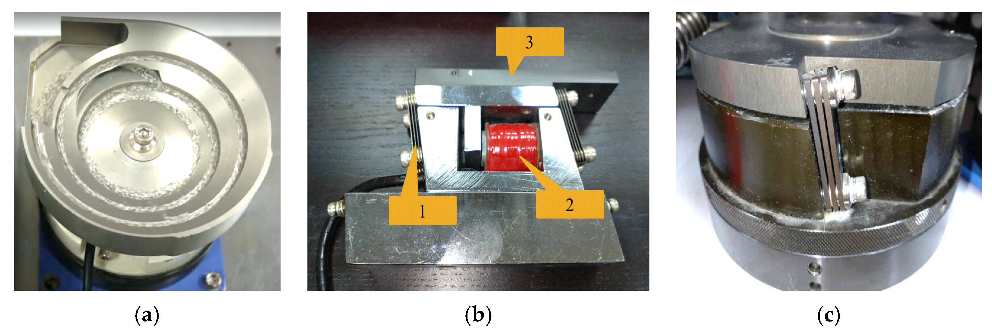
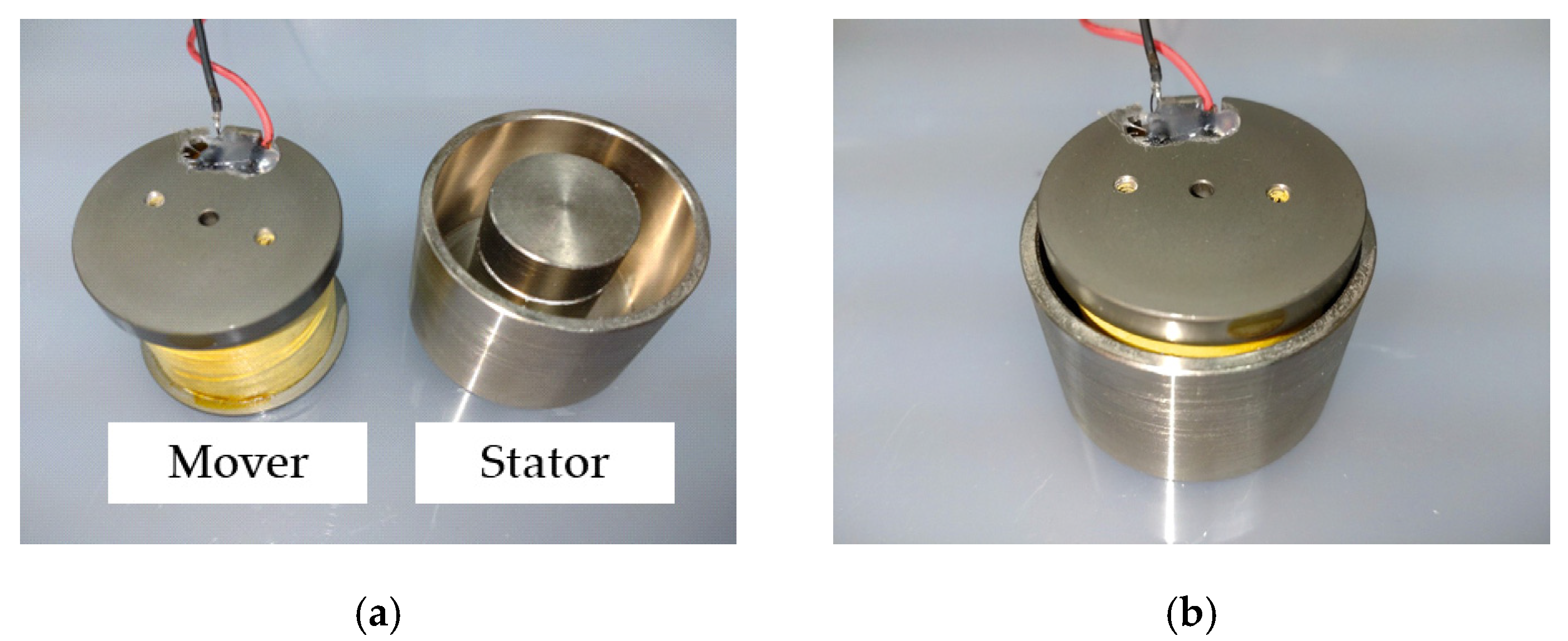
3.1. Voice Coil Actuators

Voice coil actuators are based on electromagnetic principles, operating on the magnetic field generated when current passes through a coil, thereby controlling the movement of the coil attached to the actuator. Qiao et al. provided a mathematical model of voice coil actuators and a basic description of common control mechanisms [10]; Kibria et al. studied a design of voice coil actuators using different input signals, proposing a unique VCM design and manufacturing for tactile sensing devices [11]. Feng et al. discussed the special structure of voice coil actuator as a new type of multifunctional direct-drive motor [12]. Voice coil actuators are easy to control, with high acceleration, speed, reliability, compact size, smooth force, and quick start-up speed, making them an ideal alternative to traditional motors.
The basic structure of a voice coil actuator includes two parts, as shown in Figure 4a: the mover and the stator. The mover part contains a coil with a hollow interior. The stator includes a magnet column, into which the mover is inserted, forming a structure, as shown in Figure 4b.
To ensure that the voice coil actuator does not directly contact the stator, this study uses a pair of springs in the structure to limit the position of the mover, allowing it to hover above the stator. This special arrangement can be considered the initial position ( z 0 ) of the voice coil actuator. The function of the springs is to provide a restoring force during the operation of the voice coil actuator, ensuring the mover always maintains a certain height, avoiding actual physical contact between the mover and the stator (as shown in Figure 5). The combined mover and stator do not touch each other during movement; hence, the voice coil actuator is designed as non-contact, significantly extending the lifespan of the actuator.

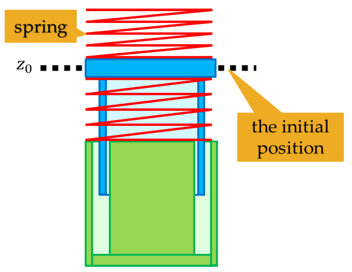
3.2. Voice Coil Actuator Motion Control

The structural design of the voice coil feeder is illustrated in Figure 6, with a set of voice coil actuators installed beneath the dedicated jig plate. The vibration is caused by the suction and repulsion force of the voice coil actuator, allowing the amplitude and frequency to be flexibly controlled by the current ( I ) and duration time t. Moreover, the longer the duration of the magnetic force, the greater the amplitude of the platform’s vertical vibration. This design enables more refined control; thus, it can also meet the sorting requirements of materials of different shapes and sizes.
The thrust generated by the voice coil actuator is described by
f = r I L B ,
where f represents the thrust acting on the coil, r is the ratio of the effective length of the coil actually in the magnetic field to the total length of the wire, I is the current size generated by the terminal voltage, L is the total length of the wire, and B is the magnetic flux density of the magnetic field. Since the force exerted by the voice coil actuator is directly proportional to the current, Equation (1) can be rewritten as
f = K f I ,
where K f is the ratio of force to current, known as a constant. When the coil cuts through the magnetic flux, a back electromotive force (EMF) is generated on the coil and represented by
E = K e B L N v ,
where K e is a constant, B is the magnetic flux density, L is the length of the coil passing through the magnetic field, N is the number of coil turns, and v is the speed of the coil cutting through the magnetic field. Since the magnetic flux density and the wire length of the voice coil actuator remain constant, the magnitude of the back EMF is directly proportional to the speed of the wire cutting through the magnetic lines of force, so Equation (2) is modified to
E = K b v = K b d x d t
where K b is the back EMF constant.
The voice coil actuator, by changing the timing and intensity of the current flow, can achieve effects with varying frequencies of ascent and descent. Its motion equation is expressed as
z t = z 0 + v t
where z t represents the position of the voice coil actuator (relative to z 0 ); z 0 is the initial position; v is the amplitude ratio; and t is time. Equation (5) allows for the control of the motion amplitude and frequency of the voice coil actuator, achieving different speeds of rising or falling effects.

3.3. PWM Control of Voice Coil Motor

Pulse Width Modulation (PWM) is a widely used technique for controlling the motion of voice coil actuators in precision applications. PWM allows for the efficient control of the actuator’s position, speed, and force by adjusting the duty cycle of a digital signal to modulate the current through the actuator. The principle behind PWM control involves generating a square wave digital signal with a variable duty cycle, where the duty cycle is defined as the percentage of one period in which a signal is active. By adjusting this duty cycle, the average power delivered to the load (in this case, the voice coil actuator) can be precisely controlled without the need for complex analog circuitry.
The relationship between the duty cycle ( D ) and the average voltage ( V a v g ) delivered to the voice coil actuator can be expressed by
V a v g = D × V s u p p l y
where V s u p p l y is the supply voltage.
For the voice coil actuator, PWM control is particularly advantageous due to its simplicity and efficiency. The actuator’s response to the PWM signal depends on its electrical and mechanical time constants. By carefully designing the PWM frequency, the actuator can be made to respond as if it were being supplied with a variable analog voltage, thereby achieving smooth and precise control over its motion [13,14]. The motion of a voice coil actuator under PWM control can be described by
x ( t ) = 1 m 0 t ( K f · I t F l o a d ) d t
where x ( t ) is the displacement of the actuator at time t , m is the mass of the moving part of the actuator, K f is the force constant of the aligner, I t is the current through the actuator at time t , and F l o a d is the load force opposing the actuator’s motion.
By implementing PWM control, the voice coil actuator can achieve high precision and efficiency in various applications, from industrial automation to precision instrumentation. This control method leverages the actuator’s inherent characteristics to provide responsive and accurate motion control, essential for tasks requiring high levels of precision and repeatability.

3.4. Force Control of Voice Coil Motor

Force control is a critical aspect in the operation of the voice coil actuator, especially in applications requiring precise manipulation or the handling of objects. This section explores the methodology for implementing force control in a voice coil actuator, supported by relevant equations and references [15,16]. The force generated by a voice coil actuator can be directly related to the current flowing through the coil, as described by
F = K f · I
where F is the force generated by the actuator, K f is the force constant of the aligner, and I is the current through the coil. To implement force control, a feedback loop is typically used to adjust the current based on the difference between the desired force and the actual force measured by a sensor. The control system can be represented by
I t = 1 K f · ( F d e s i r e d F a c t u a l )
where I t is the current supplied to the actuator at time t , F d e s i r e d is the desired force, and F a c t u a l is the actual force measured by the sensor.
Force control in voice coil actuator involves regulating the current supplied to the actuator to achieve the desired force output. Due to the voice coil actuator control method, precise output can be achieved. Simple and effective control results can be achieved for items of different weights that need to be moved to different distances. By employing force control, voice coil actuators can be used in a wide range of applications requiring precise force application, from automated assembly lines to medical devices. The key to successful force control lies in the accurate measurement of the actual force and the responsive adjustment of the current supplied to the actuator. This ensures that the desired force is consistently applied, enhancing the performance and reliability of the system.

3.5. Dual-Axis Voice Coil Feeder

Qiao et al. provided a stable voice coil actuator control method [10]. This study is based on this and then focuses on the structural design of the voice coil feeder. As shown in Figure 7, a voice coil actuator is installed on the front and rear sides of the platform. Vibration is caused by the suction and elasticity of the voice coil actuator. Combined with the individually controlled height differences on both sides, the material can achieve horizontal displacement and vertical jump. The position of the material on top of the platform is represented by
x t = x 0 + x ( t )
z t = z 0 + z ( t )
where t is time, x t is the horizontal position of the material at time t (rightward as positive, leftward as negative), z t is the vertical position of the material at time t (upward as positive, downward as negative), x 0 and z 0 are the initial horizontal and vertical positions of the material, respectively. x ( t ) and z t are the material’s movement amount in the horizontal and vertical directions. Figure 8 illustrates the control method of moving objects. Figure 8a shows the first stage. When the object needs to move to the left, the voice coil actuator on the left side of the controller will rise slowly, while the voice coil actuator on the right side will fall slowly. Figure 8b shows the second stage, where the two voice coil actuators quickly return to their initial positions, causing the object to move to the left.

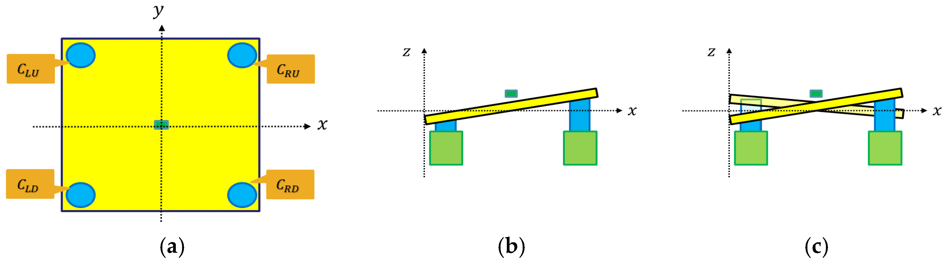
3.6. Quad-Axis Voice Coil Feeder

Figure 9 illustrates the configuration and motion principle of the power sources at the four corners of the voice coil feeder, with the advantage of generating multidimensional movements, making the feeder more flexible and multifunctional. This design allows materials to move forward, backward, left, right, or even diagonally on the platform, achieving more precise alignment and processing according to the required production operations. Additionally, the integration of PWM and force control not only facilitates complex motion patterns but also significantly improves the control performance of the feeder. By adjusting the intensity and duration of the current, as well as the force applied to the voice coil actuator, specific adjustments can be made in real time to meet the exact requirements of the task.
For the quad-axis design, since the voice coil actuators are located at the four corners, the influence of the quad axis must coordinate to achieve a reasonable platform tilt. For example, in the quad-axis voice coil feeder shown in Figure 10a, moving the two actuators on the left side downward and the two on the right side upward can tilt the platform to the left, as shown in Figure 10b. However, if the directions are changed to upward on the upper left, downward on the lower left, downward on the upper right, and upward on the lower right; the platform will be unstable, and the direction of movement cannot be confirmed. The control method for the platform’s direction is represented by.
P x < 0 , i f   ( C L U C R U ) × ( C L D C L D ) > 0   a n d   ( C L U C R U ) < 0 P x = 0 , i f   ( C L U C R U ) × ( C L D C L D ) > 0   a n d   ( C L U C R U ) = 0 P x > 0 , i f   ( C L U C R U ) × ( C L D C L D ) > 0   a n d   ( C L U C R U ) > 0 P x = u n d e f i n e d , o t h e r w i s e
P y < 0 , i f   ( C L D C L U ) × ( C R D C R U ) > 0   a n d   ( C L D C L U ) < 0 P y = 0 , i f   ( C L D C L U ) × ( C R D C R U ) > 0   a n d   ( C L D C L U ) = 0 P y > 0 , i f   ( C L D C L U ) × ( C R D C R U ) > 0   a n d ( C L D C L U ) > 0 P y = u n d e f i n e d , o t h e r w i s e
where P x represents the platform’s left–right tilt direction, P y represents the platform’s up–down tilt direction, C L U , C L D , C R U ,   C R D , respectively, indicate the height adjustment values of the upper-left, lower-left, upper-right, and lower-right corners. Multidirectional motion can be represented by four power sources, each of which gives the platform a height adjustment value. As shown in Figure 11, using different combinations of the four voice coil motors moving up and down, the platform can achieve eight horizontal directions of material movement and vertical jumping. The tilt directions of the platform are listed in Figure 11.
Utilizing the multidirectional characteristics and combining different directions for interactive use, the quad-axis voice coil feeder, through its tilt directional offset capability, can achieve precise control of the materials, including both concentration and dispersion techniques. This is achieved by combining different power source directions, as follows:
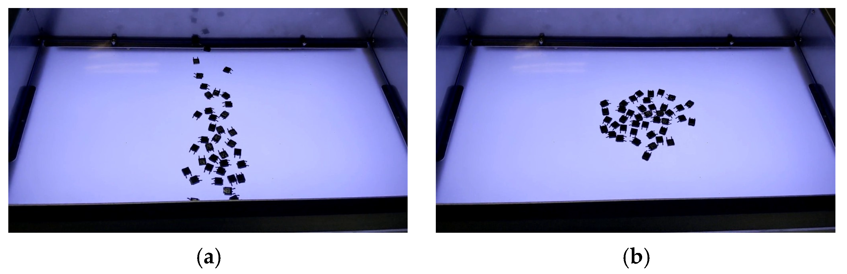
  • Concentration control: In the process of concentrating materials, gradually reducing the control force allows for more refined guidance of materials to the center or specific locations of the platform. This method is particularly suitable for scenarios requiring precise arrangement or concentration of materials. For example, in the rotational concentration operation, by gradually reducing the rotation force, materials can be concentrated toward the center while rotating, thus achieving highly precise material positioning.
  • Horizontal concentration: By simultaneously activating left and right shifts, as shown in Figure 12, materials can be concentrated in the horizontal direction. This method is suitable for concentrating materials to the center of the feeder.
  • Vertical concentration: By simultaneously activating upward and downward shifts, as shown in Figure 13, materials can be concentrated in the vertical direction. This method is suitable for concentrating materials to the vertical center of the feeder.
  • Central concentration: By separately activating horizontal and vertical concentration, as shown in Figure 14, materials can be concentrated at the center, achieving concentration of materials toward the center.
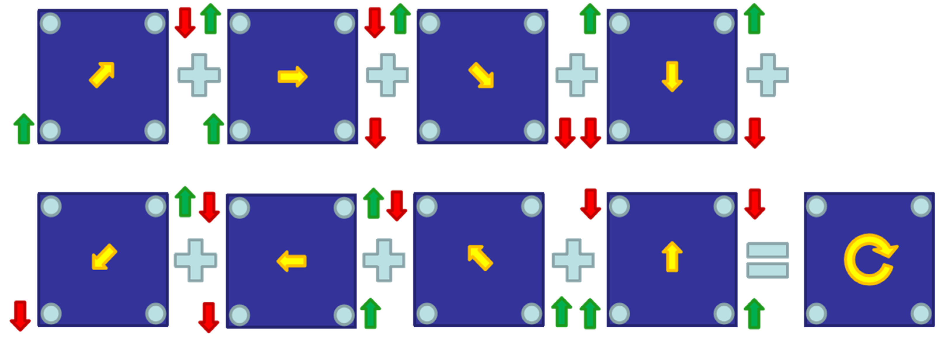
  • Rotational concentration: By activating upper-right shift, right shift, lower-right shift, downward shift, lower-left shift, left shift, upper-left shift, and upward shift, as shown in Figure 15, materials can undergo rotational movement on the platform, especially when the rotational movement is carefully adjusted to guide materials in a specific direction or location.
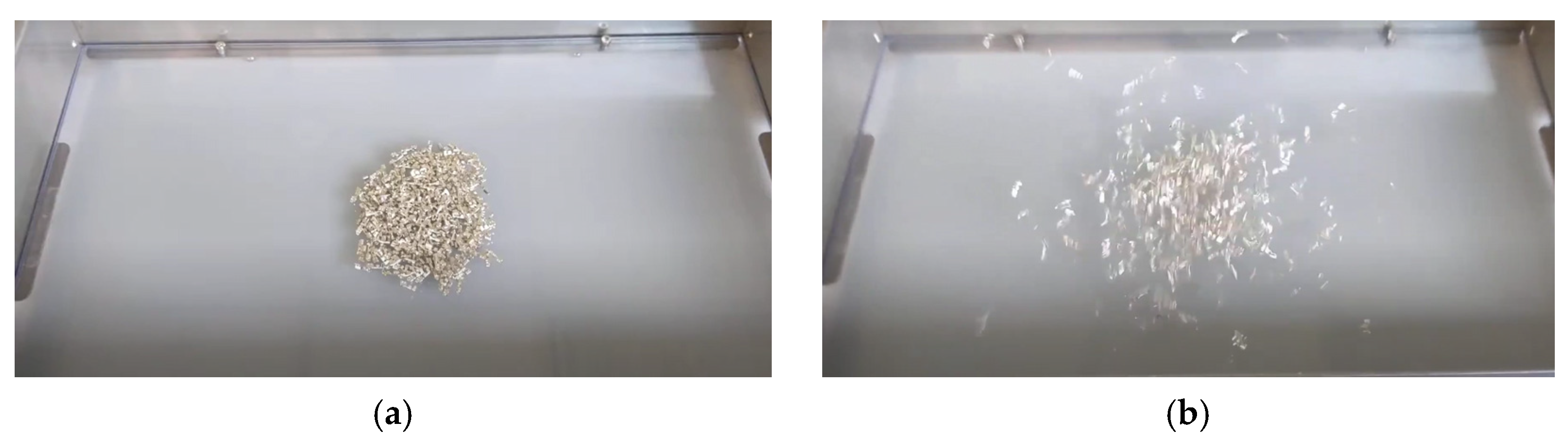
  • Dispersion control: Conversely, in the process of dispersing materials, gradually increasing the control force can effectively spread materials to different areas of the feeder platform. This operation is suitable for applications requiring uniform distribution of materials within the work area. For example, in the rotational dispersion operation, by enhancing the rotation force, materials are more widely dispersed, achieving an even distribution of materials.
Through this method of gradually adjusting the control force, the voice coil feeder can handle materials of different shapes and sizes more flexibly and precisely. Reducing the control force during concentration ensures precise concentration of materials without exceeding the target area; increasing the control force during dispersion ensures uniform distribution of materials, avoiding material aggregation. The application of this control strategy further enhances the operational flexibility and production efficiency of the voice coil feeder, enabling it to adapt to a wider range of production needs and challenges.

4. Validation Results

In the system design, there are two key frequencies: the electrical vibration frequency and the PWM cycle frequency. The electrical vibration frequency is used to control the fundamental motion of the material on the platform. It can be viewed as the vibration frequency of the movement of the physical system. It is used to control the displacement of the material on the platform to ensure the effective movement and bounce of the material. The PWM cycle frequency is used to regulate the input voltage of the voice coil actuator to provide precise control. The change in the PWM duty cycle affects the speed of the voice coil actuator. Therefore, this variation in speed results in different amounts of displacement. The electrical vibration frequency and PWM cycle frequency used in the following experiments are 12 Hz and 20 kHz, respectively.

4.1. Dual-Axis Voice Coil Feeder

The vibration effect of the dual-axis voice coil feeder is shown in Figure 16. Before the vibration, as shown in Figure 16a, screws gradually disperse outward and start falling into the jig plate after 5 s of vibration (Figure 16b). After 10 s of vibration, more than half of the screws have entered the jig plate (Figure 16c).

4.2. Quad-Axis Voice Coil Feeder

The vibration effect of the quad-axis voice coil feeder is shown in Figure 17. One experimental video can be viewed on this website: https://www.youtube.com/watch?v=aRRIWAvUmns. Utilizing the design of the four-corner power source configuration and the combination of nine-directional offsets of the voice coil feeder, effects of gathering in different positions and flipping can be achieved. Some results of the movement in some directions for the same materials on the implemented feeder are shown in Figure 18. The results of horizontal and vertical concentration are shown in Figure 19. One experimental video can be viewed on this website: https://www.youtube.com/watch?v=kROR3Nt6Va8.
In this study, the impact of different PWM duty cycles on the performance of the feeder system under the same vibration frequency conditions is explored. The experiments were conducted using a fixed vibration frequency of 12 Hz, with PWM duty cycles of 60%, 70%, 80%, 90%, and 100% to drive the voice coil. For each duty cycle, the control signals of the feeder, the material’s movement speed and the dispersion state of the material on the platform are recorded in Figure 20 and Figure 21. In the experiment, the vibration frequency was set to 12 Hz (Figure 20a). The PWM control cycle was 50 us (Figure 20b). The material used blocks, and the initial position of the material was uniformly set at the top of the image (Figure 20c). The voice coil has two wires through which control signals enter from different lines (positive terminal and negative terminal), resulting in movements in different directions. When the PWM signal enters through the positive terminal of the voice coil, the voice coil moves to z > 0 direction. When it enters through the negative terminal, the voice coil moves to z < 0 direction. Experimental waveform signals are extracted from the upper motor’s positive signal direction and the lower motor’s negative signal direction.
The waveform of different duty cycles (60%, 70%, 80%, 90%, and 100%) and the displacement and dispersion of the material under the duty cycle after one second of operation are shown in Figure 21. It shows that the same vibration frequency with different duty cycles results in different displacement amounts.
The experimental results indicate that as the PWM duty cycle increases, both the vibration amplitude of the system and the material movement speed increase. However, under high duty cycles (90–100%), the material moves faster and disperses over a larger area due to increased bouncing, making it suitable for individual picking. In contrast, under low duty cycles (60–70%), the material exhibits less bouncing and smoother horizontal movement, resulting in greater concentration, which is suitable for simultaneous picking of multiple items. Additionally, the system’s energy consumption significantly increases under high duty cycles, reaching its peak at a 100% duty cycle. These findings suggest that an appropriate PWM duty cycle can enhance system performance, allowing for different PWM settings to be used based on specific material requirements.
Figure 22 illustrates controls for upward and downward movements. Figure 22a–c represent upward movement, controlling the upper motor with a negative signal direction and the lower motor with a positive signal direction; Figure 22d–f represent downward movement, controlling the upper motor with a positive signal direction and the lower motor with a negative signal direction.
Finally, comprehensive tests were conducted on a variety of materials, including oil seals, block, washers, screws, electronic components, etc., demonstrating the feeder’s adaptability and reliability in handling different types of materials. The experimental data presented in Table 1 illustrate the good performance of the implemented bulk feeder, which is capable of handling various shapes and sizes with high flexibility and adaptability. This demonstrates the practicality of the implemented bulk feeder in the production line and highlights its potential to enhance production automation and economic efficiency. By precisely adjusting the amplitude, frequency, and duration of vibrations, the implemented bulk feeder not only ensured the expected flipping of materials during feeding but also effectively reduced the downtime between items. This record provided crucial data on material handling speed and efficiency, aiding in the overall performance assessment of the feeder.

5. Conclusions

This study uses voice coil motors to design and implement bulk feeders that can handle many kinds of materials to improve some problems existing in traditional bulk feeders. First, the implemented bulk feeder can improve the shortcomings of traditional feeders that require hardware adjustments when changing materials. The implemented feeders allow for real-time adjustment of the vibration frequency and amplitude of the voice coil actuator through programming. It allows the feeder to handle most types of materials without changing the hardware. Therefore, it can reduce the time of the hardware conversion and improve overall production efficiency. Another advantage of the voice coil feeder is energy savings and environmental friendliness. Since the voice coil actuator operates on a non-contact principle, some wear or noise is reduced during operation. This makes the implemented feeder more energy efficient and sustainable. This design not only reduces maintenance requirements and extends the lifespan of the equipment but also creates a more comfortable operating environment for operators. In this study, the primary limitation of the feeder is its restricted load capacity, which is applicable only in small- to medium-sized components on the experimental platform used in this study. It may not be suitable for oversized or heavy components. Currently, the rated total weight capacity is 2 kg for the dual-axis voice coil feeder experimental platform and 4 kg for the quad-axis voice coil feeder experimental platform, with rated dimensions smaller than 100 mm2. The material specifications vary depending on the shape of the material and its center of mass. Furthermore, the voice coil motor has a high vibration frequency of 100 vibrations per second. Therefore, the voice coil feeder using high-frequency vibration not only makes the vibration direction adjustment more flexible but also improves the problem of excessive mechanical contact and friction between the material and the platform. These characteristics allow the implemented feeder to handle some smaller materials and materials that cannot collide too much. The experimental results have proven the effectiveness and potential of the implemented dual-axis voice coil feeder and quad-axis voice coil feeder in improving bulk material handling efficiency. In summary, the bulk feeders designed and implemented using voice coil motors in this study are flexible and efficient. The implemented bulk feeders can handle a wide range of bulk materials quickly and efficiently, contributing to environmental sustainability.

Author Contributions

Conceptualization, Y.-T.Y., W.-T.W. and C.-C.W.; methodology, Y.-T.Y. and W.-T.W.; validation, Y.-T.Y. and C.-C.W.; analysis and investigation, Y.-T.Y. and W.-T.W.; writing—original draft preparation, Y.-T.Y. and W.-T.W.; writing—review and editing, C.-C.W.; visualization, W.-T.W.; project administration, C.-C.W.; and funding acquisition, C.-C.W. All authors have read and agreed to the published version of the manuscript.

Funding

This research was partly funded by the National Science and Technology Council (NSTC) of the Republic of China, under grant numbers NSTC 111-2622-E-110-024.

Data Availability Statement

All data used to support the findings of this study are available from the corresponding author upon request.

Conflicts of Interest

Author Yu-Ting Yang was employed by the company CT Green Tech Co., Ltd. Author Wen-Tan Wang was employed by the company Puton Technology Inc. The remaining authors declare that the research was conducted in the absence of any commercial or financial relationships that could be construed as a potential conflict of interest.

References

  1. Zrnić, N.; Đorđević, M.; Gašić, V. History of Belt Conveyors until the End of the 19th Century. In Explorations in the History and Heritage of Machines and Mechanisms; Springer: Cham, Switzerland, April 2022; Volume 40, pp. 210–223. [Google Scholar]
  2. Azhar, S.; Shah, S.I.A. Modeling and Analysis of a Vibratory Bowl Feeder. In Proceedings of the 2021 Seventh International Conference on Aerospace Science and Engineering (ICASE), Islamabad, Pakistan, 14–16 December 2021; pp. 1–13. [Google Scholar]
  3. Haugaard, R.L.; Iversen, T.M.; Buch, A.G.; Kramberger, A.; Mathiesen, S.F. A Flexible and Robust Vision Trap for Automated Part Feeder Design. In Proceedings of the 2022 IEEE/RSJ International Conference on Intelligent Robots and Systems (IROS), Kyoto, Japan, 23–27 October 2022; pp. 6017–6023. [Google Scholar]
  4. Kowol, P.; Nowak, P.; Lo Sciuto, G. A Control Strategy for Mechatronic Action of a Pipe Organ Using a VCM Actuator. Electronics 2023, 12, 4754. [Google Scholar] [CrossRef]
  5. Shewale, M.; Razban, A.; Deshmukh, S.; Mulik, S. Design, Development, and Implementation of the Position Estimator Algorithm for Harmonic Motion on the XY Flexural Mechanism for High Precision Positioning. Sensors 2020, 20, 662. [Google Scholar] [CrossRef] [PubMed]
  6. Chen, H.; Li, L.; Li, R.; Yu, G.; Chen, Q. Design and Analysis of a Long-Stroke and High-Precision Positioning System for Scanning Beam Interference Lithography. Electronics 2023, 12, 4960. [Google Scholar] [CrossRef]
  7. Wang, C.; Gao, P.; Wang, X.; Wang, H.; Liu, X.; Zheng, H. Mechanical Design and Experiments of a New Rotational Variable Stiffness Actuator for Hybrid Passive–Active Stiffness Regulation. Actuators 2023, 12, 450. [Google Scholar] [CrossRef]
  8. Yan, Z.; Chen, X.; Yan, M.; Hang, P. Design and Optimization of a Novel Electronic Mechanical Brake Actuator Based on Cam. Actuators 2023, 12, 329. [Google Scholar] [CrossRef]
  9. Chen, Y.; Lai, L. Design, Modeling, Testing, and Control of a Novel Fully Flexure-Based Displacement Reduction Mechanism Driven by Voice Coil Motor. Actuators 2022, 11, 228. [Google Scholar] [CrossRef]
  10. Qiao, Y.; Zhao, T.; Gui, X. Overview of Position Servo Control Technology and Development of Voice Coil Motor. CES Trans. Electr. Mach. Syst. 2022, 6, 269–278. [Google Scholar]
  11. Kibria, M.G.; Rashid, F.; Shahadat, M. Design, Fabrication and Performance Analysis of a Voice Coil Motor Using Different Input Signal. In Proceedings of the 2019 IEEE International Conference on Signal Processing, Information, Dhaka, Bangladesh, 28–30 November 2019; pp. 118–121. [Google Scholar]
  12. Feng, X.M.; Duan, Z.J.; Fu, Y.; Sun, A.L.; Zhang, D.W. The technology and application of voice coil actuator. In Proceedings of the 2011 Second International Conference on Mechanic Automation and Control Engineering, Inner Mongolia, China, 15–17 July 2011; pp. 892–895. [Google Scholar]
  13. Smith, J. Advanced Control of Voice Coil Actuators Using PWM. J. Precis. Mech. 2020, 12, 45–56. [Google Scholar]
  14. Lee, K.; Park, S. PWM Drive Strategy for High-Speed Voice Coil Motors in Precision Positioning Systems. IEEE Trans. Ind. Electron. 2021, 67, 6593–6603. [Google Scholar]
  15. Johnson, M.; Wang, D. Precise Force Control of Voice Coil Actuators. J. Autom. Control Eng. 2022, 15, 330–338. [Google Scholar]
  16. Chen, Y.; Liu, H. Adaptive Force Control for Voice Coil Motors in Precision Applications. IEEE Trans. Mechatron. 2021, 26, 410–421. [Google Scholar]
Figure 1. Two types of bulk feeder. (a) Dedicated jig plate bulk feeder. (b) Bowl bulk feeder.
Actuators 13 00281 g001
Figure 2. Cam-type structure.
Actuators 13 00281 g002
Figure 3. Mechanical structure of bowl bulk feeder. (a) The outside of bowl bulk feeder. (b) An electromagnet structure (1. platform, 2. electromagnet, 3. iron piece). (c) The iron piece of the bowl bulk feeder, as viewed from the external structure.
Actuators 13 00281 g003
Figure 4. Basic structure of voice coil actuator. (a) Composition, (b) assembly.
Actuators 13 00281 g004
Figure 5. Voice coil actuator suspension diagram. It is the initial position of voice coil actuator.
Actuators 13 00281 g005
Figure 6. Structural design of the voice coil feeder.
Actuators 13 00281 g006
Figure 7. Dual-axis voice coil feeder. (a) Platform appearance. (b) Structural design.
Actuators 13 00281 g007
Figure 8. The control method of moving objects of dual-axis voice coil feeder. (a) The first step: move slowly. (b) The second step: quickly move the reply.
Actuators 13 00281 g008
Figure 9. Quad-axis voice coil feeder. (a) Platform appearance. (b) Horizontal structure design. (c) Vertical structure design.
Actuators 13 00281 g009
Figure 10. Force voice coil actuators of quad-axis voice coil feeder. (a) Top view and definition. (b) Example for reasonable. (c) Example for non-reasonable.
Actuators 13 00281 g010
Figure 11. Corresponding to the tilt direction of the platform. (a) P x < 0   and   P y > 0 , materials shift to the upper left, (b) P x = 0   and   P y > 0 , materials shift upwards, (c) P x > 0   and   P y > 0 , materials shift to the upper right, (d) P x < 0   and   P y = 0 , materials shift to the left, (e) P x = 0   and   P y = 0 , materials vertical jumping, (f) P x > 0   and   P y = 0 , materials shift to the right, (g) P x < 0   and   P y < 0 , materials shift to the lower left, (h) P x = 0   and   P y < 0 , materials shift downwards, (i) P x > 0   and   P y < 0 , materials shift to the lower right.
Actuators 13 00281 g011
Figure 12. Horizontal concentration is the combination of left shift and right shift.
Actuators 13 00281 g012
Figure 13. Vertical concentration is the combination of upward shift and downward shift.
Actuators 13 00281 g013
Figure 14. Central concentration is the combination of horizontal concentration and vertical concentration.
Actuators 13 00281 g014
Figure 15. Rotation is the combination of upper-right shift, right shift, lower-right shift, downward shift, lower-left shift, left shift, upper-left shift, and upward shift.
Actuators 13 00281 g015
Figure 16. Vibration effects of the dual-axis voice coil feeder. (a) Before the vibration. (b) After 5 s of vibration. (c) After 10 s of vibration.
Actuators 13 00281 g016
Figure 17. Amplitude adjustment of the voice coil feeder. (a) Initial. (b) Dispersing 1 s. (c) Dispersing 2 s. (d) Dispersing 3 s.
Actuators 13 00281 g017aActuators 13 00281 g017b
Figure 18. Dispersion control results of quad-axis voice coil feeder. (a) Initial. (b) Right shift. (c) Dispersion to left. (d) Left shift. (e) Up shift. (f) Dispersion to down.
Actuators 13 00281 g018
Figure 19. Concentration control results of quad-axis voice coil feeder. (a) Vertical concentration. (b) Rotation concentration.
Actuators 13 00281 g019
Figure 20. Description of the experimental setup. (a) The vibration frequency 12 Hz. (b) The PWM control cycle was 50 us. (c) The material used blocks, and the initial position of the material was uniformly set.
Actuators 13 00281 g020
Figure 21. The waveform of different duty cycles (60%, 70%, 80%, 90%, and 100%) and the results after one second of operation. (a) 60% duty waveform. (b) Displacement and dispersion of the material about 1~2 cm under the duty cycle of 60%. (c) 70% duty waveform. (d) Displacement and dispersion of the material about 4~6 cm under the duty cycle of 70%. (e) 80% duty waveform. (f) Displacement and dispersion of the material about 5~7 cm under the duty cycle of 80%. (g) 90% duty waveform. (h) Displacement and dispersion of the material about 9~10 cm under the duty cycle of 90%. (i) 100% duty waveform. (j) Displacement and dispersion of the material about 10~12 cm under the duty cycle of 100%.
Actuators 13 00281 g021aActuators 13 00281 g021b
Figure 22. The waveform of different direction and the results after one second of operation. (a) Up direction waveform, (b) the initial position, (c) displacement and dispersion, (d) down direction waveform, (e) the initial position, (f) displacement and dispersion.
Actuators 13 00281 g022
Table 1. Experimental results of various materials for the implemented feeder.
MaterialsPictureSize (mm)Amplitude (%)Frequency (Hz)Vibration Time (s)Stationary Time (s)
Oil sealActuators 13 00281 i00115701821
BlockActuators 13 00281 i00210701821
WasherActuators 13 00281 i003Ø3.8902211
Ø5902211
Ø8901911
Ø10901711
Ø12.5901522
ScrewActuators 13 00281 i0042902011
4902211
6801811
8801811
ChipActuators 13 00281 i0052902211
4902211
6901911
Assembling partActuators 13 00281 i0063902011
4902011
5901711
Riveted partActuators 13 00281 i007Ø5902211
Ø6901911
Ø7901911
PinActuators 13 00281 i0080.1802711
0.4802511
0.5802311
1802311
2902211
5902211
12901511
SpringActuators 13 00281 i0090.1802711
0.4802511
0.5802311
Glass beadActuators 13 00281 i010Ø8901915
Ø9901715
Ø10901715
Disclaimer/Publisher’s Note: The statements, opinions and data contained in all publications are solely those of the individual author(s) and contributor(s) and not of MDPI and/or the editor(s). MDPI and/or the editor(s) disclaim responsibility for any injury to people or property resulting from any ideas, methods, instructions or products referred to in the content.

