Article

Development and Integration of Carbon–Polydimethylsiloxane Sensors for Motion Sensing in Soft Pneumatic Actuators

1
School of Aeronautics and Astronautics, Sun Yat-sen University, Shenzhen 518107, China
2
School of Mechanics and Aeronautics, Dalian University of Technology, Dalian 116024, China
3
School of Advanced Manufacturing, Sun Yat-Sen University, Shenzhen 518107, China
*
Author to whom correspondence should be addressed.
These authors contributed equally to this work.
Actuators 2024, 13(8), 285; https://doi.org/10.3390/act13080285
Submission received: 27 June 2024 / Revised: 24 July 2024 / Accepted: 26 July 2024 / Published: 28 July 2024
(This article belongs to the Special Issue Advanced Technologies in Soft Pneumatic Actuators)

Abstract

:
Drawing inspiration from the intricate soft structures found in nature, soft actuators possess the ability to incrementally execute complex tasks and adapt to dynamic and interactive environments. In particular, the integration of sensor data feedback allows actuators to respond to environmental stimuli with heightened intelligence. However, conventional rigid sensors are constrained by their inherent lack of flexibility. The current manufacturing processes for flexible sensors are complex and fail to align with the inherent simplicity of soft actuators. In this study, to facilitate the straightforward and consistent sensing of soft pneumatic actuators, carbon–polydimethylsiloxane (CPDMS) materials were employed, utilizing 3D printing and laser-cutting techniques to fabricate a flexible sensor with ease. The preparation of standard tensile specimens verified that the sensor exhibits a fatigue life extending to several hundred cycles and determined its gauge factor to be −3.2. Experimental results indicate that the sensor is suitable for application in soft pneumatic actuators. Additionally, a printed circuit board (PCB) was fabricated and the piecewise constant curvature (PCC) kinematic method was utilized to enable real-time pose estimation of the soft pneumatic actuator. Compared with computer vision methods, the pose estimation error obtained by the sensing method is as low as 4.26%. This work demonstrates that this easily fabricated sensor can deliver real-time pose feedback for flexible pneumatic actuators, thereby expanding the potential application scenarios for soft pneumatic actuators (SPAs).

1. Introduction

Nature’s exploitation of soft structures for effective movement and interaction within complex environments informs robotic engineers’ integration of soft technologies into their design paradigms [1,2,3]. Soft actuators, inspired by the flexible appendages of living organisms and made of soft substrate materials, endow actuators with novel application capabilities to manipulate various objects and adaptively interact with complex changing environments [4,5,6,7]. With these compliant properties, soft actuators offer potential for industrial production [8], medical treatment [9], and even post-disaster rescue [10].
Soft actuators, which are driven by pneumatic, cable, and shape memory polymers, dielectric elastomers, and responsive hydrogel, offer superior simplicity, softness, and lightness compared to rigid actuators [11,12,13]. For example, Ke et al. proposed a stiffness preprogrammable soft pneumatic actuator by discretely presetting gradient geometrical or materials distributions. Their actuator could be potentially used in those specific-purposed, single, and repetitive application scenarios where varying curvature, conformal, and efficient interaction are needed [14]. Zhang et al. presented a cable-driven continuum actuator with preprogrammable stiffness. This actuator offers an effective route for efficient interactions such as transverse movement through the elbow pipes [15]. Mattmann et al. proposed an actuator made of a unique biocompatible thermoset polymer and integrated it into a magnetic actuation system for the precise actuation of one or multiple tools [16]. Godaba et al. demonstrated the efficient underwater locomotion of a jellyfish robot utilizing dielectric elastomer actuators which exhibit muscle-like properties, including large deformation and high energy density [17]. Soft actuators have garnered significant attention because of their intricate motion capabilities, straightforward control inputs, and low-impedance interactions [18]. Integrating sensors capable of providing real-time feedback on multiple parameters is essential for soft actuators, as this enables them to intelligently adapt to environmental cues, achieving greater complexity and functionality, thereby precisely mimicking the intrinsic responsiveness of biological systems [19]. Soft actuators can provide sufficient output force while achieving beneficial relative accuracy in contraction, extension, bending, and twisting. This necessitates sensors that can continuously detect these deformation modes to facilitate and support the operation of soft actuators [20]. However, traditional rigid sensing components in soft actuators significantly limit the deformation and compliance of the underlying structure, thereby restricting the application potential of these actuators [21].
To keep the flexibility and extensibility of soft actuators, soft sensors with biological properties have been developed and extensively studied [22,23,24,25,26]. Methods for achieving soft sensing include resistive sensors, capacitive sensors, and optical sensors for strain, curvature, texture, and force used in prosthetic hands [27], as well as optical tactile soft sensors with external and proprioceptive sensing capabilities [28]. Resistive strain sensors are made of conductive materials or conductive liquids embedded in flexible and stretchable substrates. When mechanical strain is applied, the entire structure stretches, leading to changes in the resistance of the conductive film or liquid, indicating strain within the continuum [29]. Capacitive strain sensors consist of soft dielectric layers and stretchable electrodes; mechanical strain induces changes in the composite structure’s thickness, reflected as variations in capacitance, thereby indicating strain in the actuator [30,31]. To date, several representative strain sensors, using metals/semiconductors, graphene, the conductive polymer, and microfluidic materials as conductive materials combined with elastomeric substrates, have been successfully fabricated [32]. For example, Park et al. detected multi-axis strains and contact pressure by filling a multilayered microchannel in an elastomer matrix with a conductive liquid [33]. However, the presence of the oxide layer which prevents effective electrical connections between the dispersed particles reduces the sensing accuracy. Chun et al. proposed a sensor fabricated by introducing single-layer graphene as a force material with a conductive film to detect various types of strain induced via stretching, bending, and torsion [34]. Lee et al. reported the direct synthesis of large-scale graphene films using chemical vapor deposition on thin nickel layers and transferred them to pre-strained PDMS substrates to produce the soft sensors [35]. Hu et al. reported a high-sensitivity, large-strain bilayer carbon black/PDMS strain sensor, exhibiting ultra-high sensitivity with a gauge factor (GF) of over 60 [36]. Despite their remarkable sensing performance, the complex production process hinders the high-throughput manufacturing of these sensors [37]. Additionally, previous studies have shown that as strain increases, sensors exhibit positive strain gain, necessitating a wider readable range and higher resistance thresholds on the PCB, thereby complicating data processing. Thus, it is essential to design a soft sensor that balances sensing capability and production complexity, aligns with the simple manufacturing and straightforward control inputs of soft pneumatic actuators, and reduces resistance reading thresholds to simplify data processing.
To solve the above problems, a simpler strain sensor was proposed that is produced easily for soft actuators. Utilizing 3D printing technology and photolithography, a carbon–polydimethylsiloxane (CPDMS) layer with tailored patterns was fabricated and the sensor was encapsulated within PDMS sheets. A printed circuit board (PCB) was designed to filter the CPDMS signal and accurately measure its resistance. The experimental results showed that the CPDMS sensor possesses a gauge factor (GF) of −3.2 and endures 500 fatigue cycles, effectively sensing strain. This system was integrated into a soft pneumatic actuator (SPA) and kinematic modeling was employed to detect SPA movements. Comparative analysis using computer vision revealed a minimum error margin of just 4.26%, demonstrating the sensor’s suitability for SPA applications.

2. Materials and Methods

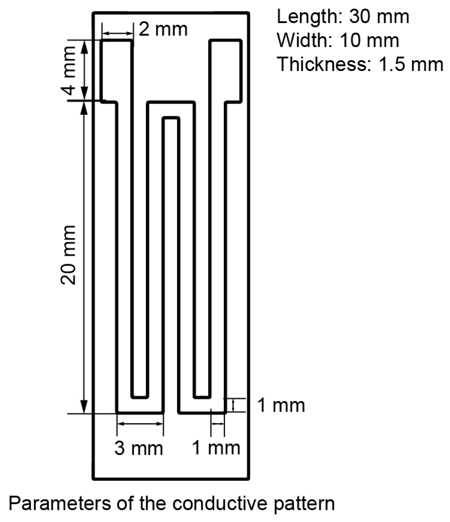
2.1. Design and Fabrication of CPDMS Sensors

Conductive elastomers were prepared by incorporating carbon black (ECP-300JD, Lion, Tokyo, Japan) nanoparticles into PDMS (Sylgard 184, Dow Corning, Midland, MI, USA). A low concentration of carbon black results in poor conductivity of the material, whereas a high concentration hinders the solidification of the CPDMS structure. After optimization, a concentration of 10 wt.% was selected. Upon solidification, the spacing between carbon black nanoparticles typically elongates under tensile strain, resulting in decreased conductivity, increased resistivity (ρ), and increased length (L). However, since the Poisson’s ratio of PDMS is greater than zero, the cross-sectional area (S) decreases. Consequently, the corresponding resistance (R = ρ × L ÷ S) increases. The sensitive gate structure of the resistance strain gauge was referred to and the sensitive gate size was optimized accordingly [38,39]. To achieve negative strain gain, the length was reduced and the width was increased at the inflection point as Figure 1. This adjustment ensured that, when stretched axially, the cross-sectional area (S) at the inflection point increased, while the corresponding changes in length (L) and resistivity (ρ) remained minimal. This design reduced the resistance (R) of the CPDMS when stretched.
To prepare this low-cost sensor suitable for soft actuators, the production process was subdivided into three steps and their costs were calculated. The detailed manufacturing process is shown in Figure 2. Step 1: As shown in Figure 2A, a PDMS pad with a thickness of 0.5 mm was prepared using a casting method. First, the PDMS solution and curing agent (Sylgard 184, Dow Corning, Midland, MI, USA) components were stoichiometrically mixed at a weight ratio of 10:1. To reduce potential structural abnormalities caused by bubbles, the composite was vacuum degassed using a negative pressure pump for 20 min. Subsequently, the mixture was injected into a mold made using a 3D printer (Shape 1+, Rayshape, Shenzhen, China) through a syringe. The mixture was cured in an oven (DZF-6090, Bonakeji, Beijing, China) at 70 °C for about one hour and then taken out to obtain a PDMS pad. Step 2: As shown in Figure 2B, a conductive pattern was prepared. Another batch of uncured PDMS was mixed with 10% by weight of carbon black (ECP-300JD, Lion, Tokyo, Japan). Use a stirrer (SP-OES-20M, SuRui, Shanghai, China) to stir the mixture for 1 h to make the carbon black particles evenly distributed in the solution. The mixed CPDMS was applied on the film pattern cut by the laser cutter (CMH1610-B-A, YueMing, Guangzhou, China), the conductive layer was put into the oven, set to 70 °C, and baked for 4 h. Step 3: As shown in Figure 2C, silver pastes was utilized to paste the electrodes on the baked soft layer connection points, and then liquid PDMS was used to paste the gaskets made in Step 1 for upper and lower packaging to complete the sensor production.

2.2. Strain Response of CPDMS Sensors

For the measurement of the gauge factor (GF) and fatigue effect of the CPDMS sensor, a Mark-10 tensile tester (ESM303, Mark-10, Copiague, New York, NY, USA) was used to quantify the strain behavior, and a resistance meter (YP2512, YongPeng, Ningbo, China) was used to obtain feedback on the resistance value. In the preparation test stage, the CPDMS sensor was pasted on the center of the tensile standard specimen prepared by PDMS casting, as shown in Figure 3A. The length of the standard specimen was 200 mm, the width was 20 mm, and the thickness was 4.0 mm. Since the materials are all PDMS, it can be assumed that the standard axial tensile strain is approximately equal to the tensile strain of the CPDMS sensor. The test was arranged as shown in Figure 3B and recorded using a camera (FDR AX60, Sony, Tokyo, Japan). The stretching and retraction speed of Mark-10 was 1 mm per minute, and the stretching was stopped when the strain reached 20%, twice the max strain of the SPA. These experiments were carried out at normal room temperature (about 25 °C) and humidity level (about 30% RH). (Video S1, Supporting Information) The resistance acquisition frequency was 1 Hz. The data were calculated, analyzed, and fitted using the software OriginLab (v2024b, OriginLab, Northampton, MA, USA).

2.3. Data Processing System Design

As shown in Figure 4, to achieve the high-precision measurement of CPDMS resistance, a complete impedance detection hardware system was designed based on the principle of a complex impedance detection circuit to realize real-time acquisition and calculation of resistance. Table 1 explains the abbreviations used in the figure. The printed circuit board (PCB) collects the sinusoidal excitation signal generated by the signal generator (HDG2032B, Hantek, Qingdao, China) and compares it with the signal generated by the sensor end to calculate the real-time resistance of the sensor. The resistance detection circuit consists of the AD8667 output op amp and the four-channel amplifier LM324 and is measured by the vector voltage and current method. The PCB uses the STM32F4 microprocessor to collect and filter the signal, call the built-in digital signal processing library (DSP) to realize the Fourier transform, and finally output the resistance value.

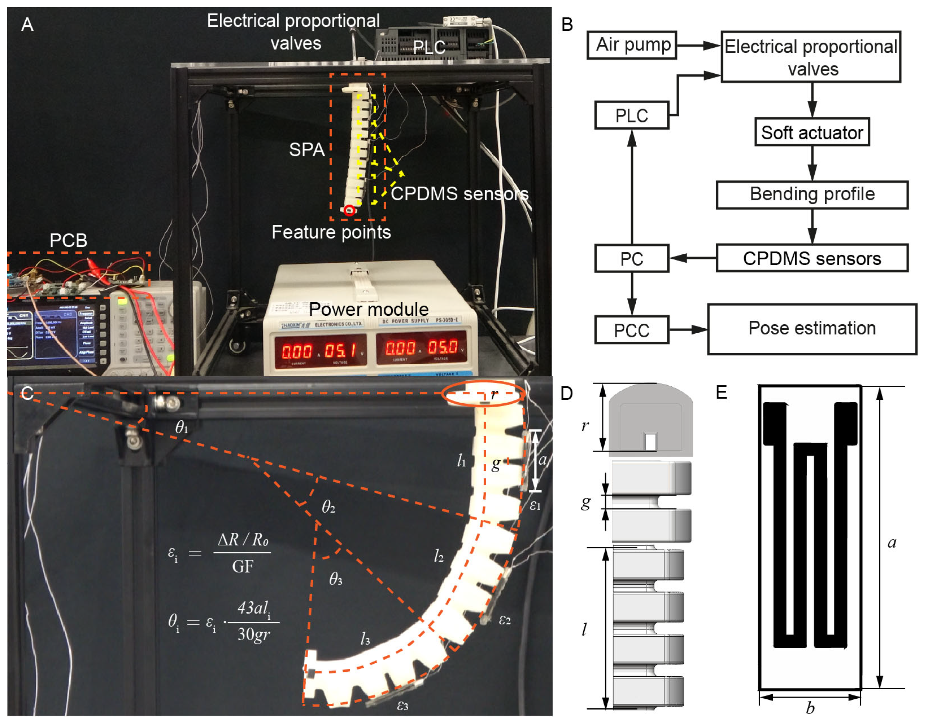
2.4. Actuator Position Verification

To evaluate the effect of CPDMS on the position and posture perception of soft pneumatic actuators, an experimental device was built, including the soft pneumatic actuator, a camera (FDR AX60, Sony, Tokyo, Japan), an air pump (OTS-550, Excellence, Chongqing, China), a valve (ITV0010-2N, SMC, Tokyo, Japan), a programmable logic controller (PLC) (S7-200 SMART, Siemens, Nuremberg, Germany), and three CPDMS sensors (Figure 5E). Table 2 details the specific size parameters illustrated in the figure. The PLC was used to control the SPA and record the corresponding bending deformation through the camera. The end of the SPA was marked, and its motion trajectory was tracked using the software Tracker (v6.2.0, Cabrillo College, Aptos, CA, USA). The sensor data were fed back to the computer through the PCB, and these data, combined with piecewise constant curvature (PCC) kinematic modeling, were used to track the SPA trajectory and compare the error.

3. Results

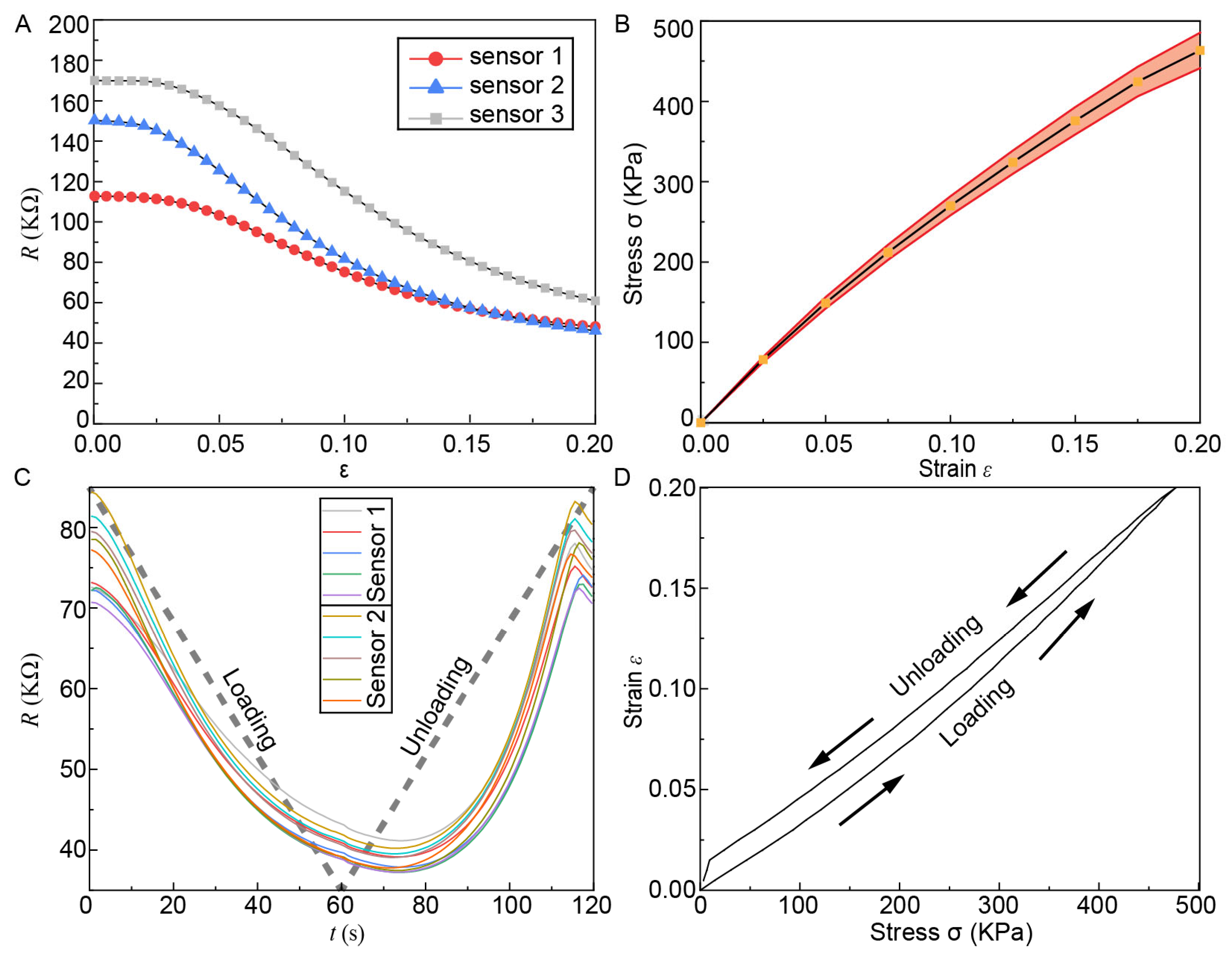
3.1. CPDMS Measurement Results

The standard component, equipped with the CPDMS sensor, was mounted on a universal testing machine, and subjected to tensile displacement. The measurement results are presented in Figure 6. As illustrated in Figure 6A, the resistance of CPDMS decreased with increasing tensile strain, primarily due to the widening of the cross-sectional area at the turning point during the stretching process. Figure 6B depicts the relationship between tensile stress and strain of the sensor. Figure 6C shows the corresponding time measurements for sensors 1 and 2. Sensors 1 and 2 underwent five loading–unloading cycles, with their real-time resistance values recorded. The standard component transitioned from 0% to 20% strain and back to 0% strain, with the loading process spanning from 0 to 60 s and the unloading process from 60 to 120 s, exhibiting a resistance hysteresis of τ = 12 s. Figure 6D illustrates the stress–strain relationship of sensor 1 during the loading and unloading processes.

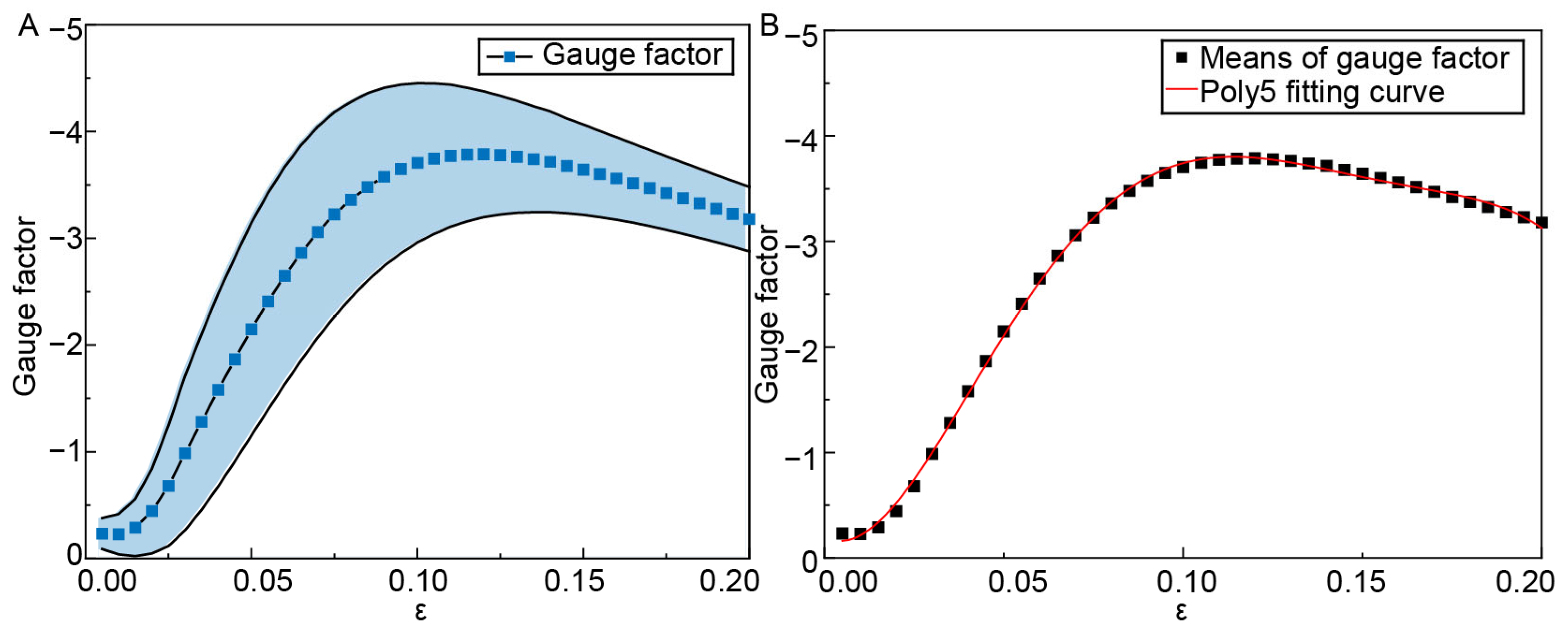
3.2. Gauge Factors of CPDMS Strain Sensors

Due to the simplicity of the fabrication process, a batch of CPDMS sensors was fabricated, and the gauge factor (GF) was measured, as depicted in Figure 7A. Here, GF is defined as (ΔR/R0)/ε. The fitted GF curve is presented in Table 3. When the strain reached 20%, the GF was −3.2, which is adequate for SPA deformation sensing. The GF of different sensors varied slightly, likely due to the uneven application of CPDMS.

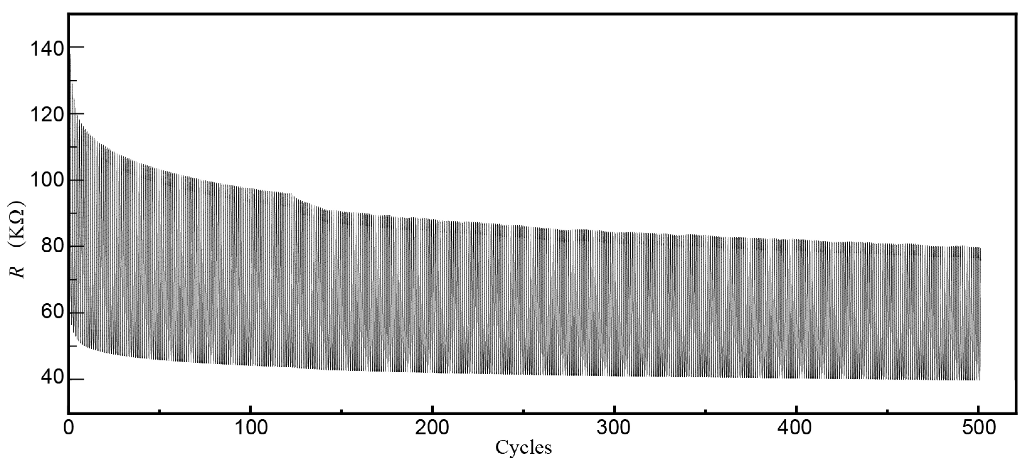
3.3. Durability of the CPDMS Strain Sensors

To assess the fatigue life of the CPDMS sensor, a cycle test was performed, with the results presented in Figure 8. The initial resistance of the CPDMS strain sensor was 122 kΩ. The change in peak resistance value was likely due to the hysteresis effect. The CPDMS did not return to the initial R0 before entering the next cycle, causing a gradual decrease in the peak resistance of each cycle.

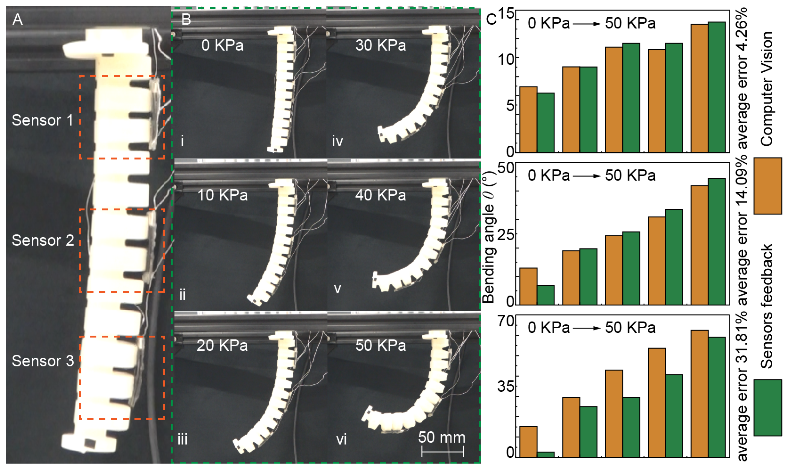
3.4. Actuator Sensing Based on CPDMS

To verify that the easily prepared CPDMS sensor could effectively perceive SPA motion posture, three sensor segments were attached to the suspended SPA, as illustrated in Figure 9A. Considering the influence of gravity on the SPA, a segmented constant curvature model divided into three segments was selected and the perception accuracy was determined by measuring the bending angle. Using a proportional solenoid valve controlled by a PLC, the air pressure was steadily increased from 0 kPa to 50 kPa, as shown in Figure 9B. (Video S2, Supporting Information) By recording the position information of feature points, the curvature of the three constant curvature segments was measured. The sensor data were substituted into the previously fitted function to obtain the corresponding gauge factor, and then the strain of each segment was calculated to determine the bending angle. As shown in Figure 9C, the first sensor exhibited the best perception accuracy, with an error of only 4.26% compared to vision. The perception accuracy of the third segment was slightly lower, primarily due to the large data gap measured by sensor 3 at 10 kPa. The reasons for these errors may include the following: 1. The handmade SPA was not completely symmetrical, causing the bending to deviate from a pure 2D movement, leading to visual measurement errors; 2. The SPA underwent both bending and twisting, and the CPDMS sensor cannot distinguish between these motions, causing interference. Except for some obvious errors, the SPA bending behavior feedback from the CPDMS sensor aligned well with computer vision data, indicating that the CPDMS sensor could effectively track the SPA’s bending movements.

4. Conclusions and Discussion

This study introduces a soft sensor constructed from a composite of PDMS and carbon black. This sensor exhibits a negative gain coefficient, is straightforward to fabricate, and meets the requirements of soft pneumatic actuators (SPAs). Measuring just 1 cm by 3 cm, the sensor is suitable for a range of SPA applications, offering a relatively simple closed-loop control and sensing method for SPA motion. Initially, during the preparation of the CPDMS sensor, the PDMS film is cast and laser cutting is employed to create the desired pattern, thus obviating the need for costly and complex Ultraviolet Lithography equipment. In tensile tests, PDMS demonstrates excellent tensile properties, with its maximum stress exceeding 400 kPa, making it highly suitable for SPA applications. Owing to the structural parameter design, stretching the sensor causes a significant widening of the cross-sectional area at the inflection point of its pattern, while the axial section does not narrow considerably. This results in the negative gain coefficient characteristic where strain increase leads to resistance reduction. After a resting period, the particles tend to revert to their original state, causing the resistance to return to the R0 baseline. Loading-unloading experiments reveal that the CPDMS sensor exhibits a perceptual hysteresis effect, evidenced by the peak resistance remaining lower than R0 after strain is removed in the fatigue test. The sensor was mounted on the SPA and its performance was compared with visual measurements. The inability of the SPA to achieve full two-dimensional bending resulted in computer vision measurement errors and sensor torsion errors. However, sensor 1 exhibited a measurement error of only 4%, demonstrating the potential of CPDMS in SPA motion perception.
The sensor’s perceptual effect was characterized by measuring the gauge factor (GF) value. The GF curve exhibits strong nonlinear characteristics, attributed to the elastic properties of the PDMS substrate. At low strain levels, the GF increases rapidly. Beyond 10% strain, the GF plateaus and remains relatively stable, indicating that the CPDMS sensor may be more accurate for measuring large strains. During the experiment, it was observed that the CPDMS material exhibits sensitivity to temperature and humidity. Consequently, environmental factors result in variations in the initial R0, which may account for errors in the motion perception process. A CPDMS sensor from the same batch was selected for testing. It was placed at standard room temperature (approximately 25 °C) and humidity level (around 30% RH), with an initial R0 of 81.80 kΩ. A temperature sensor was attached to its surface, and it was heated in an oven. The R0 resistance at 0 strain was recorded at 5-degree Celsius intervals. As the temperature increased from 30 °C to 100 °C, the corresponding R0 values were 81.8, 82.44, 83.81, 86.42, 89.03, 93.20, 97.80, 102.46, 109.18, 117.90, 121.34, 128.08, 138.32, 145.85, and 154.42 KΩ. It is evident that, as the ambient temperature rises, the R0 value also gradually increases. The CPDMS was soaked in water for one day to achieve 100% humidity, resulting in a lower R0 of 58.83 KΩ. Additionally, errors introduced by computer vision have resulted in suboptimal sensor comparison outcomes. To enhance the accuracy of this sensor, comparison flexible strain sensors are being searched to identify superior options for improving sensing precision. In future work, we will explore the integration of more inert carbon materials and alternative elastic substrates, including self-healing materials, to prevent fatigue damage and extend the lifespan of CPDMS sensors. Additionally, to enhance sensor robustness and mitigate errors caused by fatigue life and hysteresis effects, we propose two solutions: enhancing sensor adaptability to environmental conditions to reduce the perceived hysteresis effect, and optimizing the prediction algorithm on the PCB to minimize the negative impact of hysteresis.

Supplementary Materials

The following supporting information can be downloaded at: https://www.mdpi.com/article/10.3390/act13080285/s1, Video S1: axial tensile test; Video S2: CPDMS application in SPA.

Author Contributions

K.M. and S.W. equally contributed to this paper. Conceptualization was carried out by K.M. and S.W.; the methodology was developed by K.M., S.W., J.Z. (Jie Zhang), and J.W.; the software was provided by K.M., S.W., Y.Z., and M.S.; validation was performed by Y.Z.; formal analysis was conducted by S.W. and Y.Z.; the investigation was led by K.M. and J.Z. (Jie Zhang); resources were gathered by S.W., M.S., and J.Z. (Jinxiu Zhang); the original draft preparation was conducted by K.M.; writing—review and editing was handled by S.W. and J.Z. (Jie Zhang); the visualizations were created by K.M. and Y.Z.; and supervision, project administration, and funding acquisition were all overseen by J.Z. (Jinxiu Zhang), J.W., and J.Z. (Jie Zhang) All authors have read and agreed to the published version of the manuscript.

Funding

This research was funded by the Shenzhen Science and Technology Program (Grant No. GXWD20201231165807008, 20200830220051001, Grant No. 20220817165030002), the National Natural Science Foundation of China (No. 52275298), and Postdoctoral Fellowship Program of CPSF (No. GZC20240192).

Data Availability Statement

The data and copyright that support the findings of this study are available from the corresponding author upon reasonable request.

Conflicts of Interest

The authors declare no conflicts of interest.

References

  1. Li, S.; Bai, H.; Shepherd, R.F.; Zhao, H. Bio-Inspired Design and Additive Manufacturing of Soft Materials, Machines, Robots, and Haptic Interfaces. Angew. Chem. Int. Ed. 2019, 58, 11182–11204. [Google Scholar] [CrossRef]
  2. Pinskier, J.; Howard, D. From Bioinspiration to Computer Generation: Developments in Autonomous Soft Robot Design. Adv. Intell. Syst. 2022, 4, 2100086. [Google Scholar] [CrossRef]
  3. Boyraz, P.; Runge, G.; Raatz, A. An Overview of Novel Actuators for Soft Robotics. Actuators 2018, 7, 48. [Google Scholar] [CrossRef]
  4. Trivedi, D.; Rahn, C.D.; Kier, W.M.; Walker, I.D. Soft robotics: Biological inspiration, state of the art, and future research. Appl. Bionics Biomech. 2008, 5, 99–117. [Google Scholar] [CrossRef]
  5. Cianchetti, M.; Licofonte, A.; Follador, M.; Rogai, F.; Laschi, C. Bioinspired Soft Actuation System Using Shape Memory Alloys. Actuators 2014, 3, 226–244. [Google Scholar] [CrossRef]
  6. Walker, J.; Zidek, T.; Harbel, C.; Yoon, S.; Strickland, F.S.; Kumar, S.; Shin, M. Soft Robotics: A Review of Recent Developments of Pneumatic Soft Actuators. Actuators 2020, 9, 3. [Google Scholar] [CrossRef]
  7. Ma, K.; Chen, X.; Zhang, J.; Xie, Z.; Wu, J.; Zhang, J. Inspired by Physical Intelligence of an Elephant Trunk: Biomimetic Soft Robot With Pre-Programmable Localized Stiffness. IEEE Robot. Autom. Lett. 2023, 8, 2898–2905. [Google Scholar] [CrossRef]
  8. Yang, Y.; Vella, K.; Holmes, D.P. Grasping with Kirigami Shells. Sci. Robot. 2021, 6, eabd6426. [Google Scholar] [CrossRef]
  9. Feng, M.; Yang, D.; Gu, G. High-Force Fabric-Based Pneumatic Actuators With Asymmetric Chambers and Interference-Reinforced Structure for Soft Wearable Assistive Gloves. IEEE Robot. Autom. Lett. 2021, 6, 3105–3111. [Google Scholar] [CrossRef]
  10. Ma, K.; Zhang, J.; Sun, R.; Chang, B.; Zhang, S.; Wang, X.; Wu, J.; Zhang, J. Synergizing Structural Stiffness Regulation with Compliance Contact Stiffness: Bioinspired Soft Stimuli-Responsive Materials Design for Soft Machines. Adv. Eng. Mater. 2024, 26, 2400461. [Google Scholar] [CrossRef]
  11. Rus, D.; Tolley, M.T. Design, Fabrication and Control of Soft Robots. Nature 2015, 521, 467–475. [Google Scholar] [CrossRef]
  12. Whitesides, G.M. Soft Robotics. Angew. Chem. Int. Ed. 2018, 57, 4258–4273. [Google Scholar] [CrossRef]
  13. Jiao, D.; Zhu, Q.L.; Li, C.Y.; Zheng, Q.; Wu, Z.L. Programmable Morphing Hydrogels for Soft Actuators and Robots: From Structure Designs to Active Functions. Acc. Chem. Res. 2022, 55, 1533–1545. [Google Scholar] [CrossRef]
  14. Ke, X.; Jang, J.; Chai, Z.; Yong, H.; Zhu, J.; Chen, H.; Guo, C.F.; Ding, H.; Wu, Z. Stiffness Preprogrammable Soft Bending Pneumatic Actuators for High-Efficient, Conformal Operation. Soft Robot. 2022, 9, 613–624. [Google Scholar] [CrossRef]
  15. Zhang, J.; Li, Y.; Kan, Z.; Yuan, Q.; Rajabi, H.; Wu, Z.; Peng, H.; Wu, J. A Preprogrammable Continuum Robot Inspired by Elephant Trunk for Dexterous Manipulation. Soft Robot. 2023, 10, 636–646. [Google Scholar] [CrossRef]
  16. Mattmann, M.; De Marco, C.; Briatico, F.; Tagliabue, S.; Colusso, A.; Chen, X.-Z.; Lussi, J.; Chautems, C.; Pané, S.; Nelson, B. Thermoset Shape Memory Polymer Variable Stiffness 4D Robotic Catheters. Adv. Sci. 2022, 9, 2103277. [Google Scholar] [CrossRef]
  17. Godaba, H.; Li, J.; Wang, Y.; Zhu, J. A Soft Jellyfish Robot Driven by a Dielectric Elastomer Actuator. IEEE Robot. Autom. Lett. 2016, 1, 624–631. [Google Scholar] [CrossRef]
  18. Polygerinos, P.; Correll, N.; Morin, S.A.; Mosadegh, B.; Onal, C.D.; Petersen, K.; Cianchetti, M.; Tolley, M.T.; Shepherd, R.F. Soft Robotics: Review of Fluid-Driven Intrinsically Soft Devices; Manufacturing, Sensing, Control, and Applications in Human-Robot Interaction. Adv. Eng. Mater. 2017, 19, 1700016. [Google Scholar] [CrossRef]
  19. Cianchetti, M.; Laschi, C.; Menciassi, A.; Dario, P. Biomedical Applications of Soft Robotics. Nat. Rev. Mater. 2018, 3, 143–153. [Google Scholar] [CrossRef]
  20. Tawk, C.; Alici, G. A Review of 3D-Printable Soft Pneumatic Actuators and Sensors: Research Challenges and Opportunities. Adv. Intell. Syst. 2021, 3, 2000223. [Google Scholar] [CrossRef]
  21. Lee, C.; Kim, M.; Kim, Y.J.; Hong, N.; Ryu, S.; Kim, H.J.; Kim, S. Soft Robot Review. Int. J. Control Autom. Syst. 2017, 15, 3–15. [Google Scholar] [CrossRef]
  22. Schwartz, G.; Tee, B.C.-K.; Mei, J.; Appleton, A.L.; Kim, D.H.; Wang, H.; Bao, Z. Flexible Polymer Transistors with High Pressure Sensitivity for Application in Electronic Skin and Health Monitoring. Nat. Commun. 2013, 4, 1859. [Google Scholar] [CrossRef]
  23. Wang, X.; Gu, Y.; Xiong, Z.; Cui, Z.; Zhang, T. Silk-Molded Flexible, Ultrasensitive, and Highly Stable Electronic Skin for Monitoring Human Physiological Signals. Adv. Mater. 2014, 26, 1336–1342. [Google Scholar] [CrossRef]
  24. Chou, H.-H.; Nguyen, A.; Chortos, A.; To, J.W.F.; Lu, C.; Mei, J.; Kurosawa, T.; Bae, W.-G.; Tok, J.B.-H.; Bao, Z. A Chameleon-Inspired Stretchable Electronic Skin with Interactive Colour Changing Controlled by Tactile Sensing. Nat. Commun. 2015, 6, 8011. [Google Scholar] [CrossRef]
  25. Ge, J.; Sun, L.; Zhang, F.-R.; Zhang, Y.; Shi, L.-A.; Zhao, H.-Y.; Zhu, H.-W.; Jiang, H.-L.; Yu, S.-H. A Stretchable Electronic Fabric Artificial Skin with Pressure-, Lateral Strain-, and Flexion-Sensitive Properties. Adv. Mater. 2016, 28, 722–728. [Google Scholar] [CrossRef]
  26. Chen, S.; Wei, Y.; Wei, S.; Lin, Y.; Liu, L. Ultrasensitive Cracking-Assisted Strain Sensors Based on Silver Nanowires/Graphene Hybrid Particles. ACS Appl. Mater. Interfaces 2016, 8, 25563–25570. [Google Scholar] [CrossRef]
  27. Zhao, H.; O’Brien, K.; Li, S.; Shepherd, R.F. Optoelectronically Innervated Soft Prosthetic Hand via Stretchable Optical Waveguides. Sci. Robot. 2016, 1, eaai7529. [Google Scholar] [CrossRef]
  28. Xiang, C.; Guo, J.; Rossiter, J. Soft-Smart Robotic End Effectors with Sensing, Actuation, and Gripping Capabilities. Smart Mater. Struct. 2019, 28, 055034. [Google Scholar] [CrossRef]
  29. Amjadi, M.; Yoon, Y.J.; Park, I. Ultra-Stretchable and Skin-Mountable Strain Sensors Using Carbon Nanotubes–Ecoflex Nanocomposites. Nanotechnology 2015, 26, 375501. [Google Scholar] [CrossRef]
  30. Cai, L.; Song, L.; Luan, P.; Zhang, Q.; Zhang, N.; Gao, Q.; Zhao, D.; Zhang, X.; Tu, M.; Yang, F.; et al. Super-Stretchable, Transparent Carbon Nanotube-Based Capacitive Strain Sensors for Human Motion Detection. Sci. Rep. 2013, 3, 3048. [Google Scholar] [CrossRef]
  31. Amjadi, M.; Kyung, K.-U.; Park, I.; Sitti, M. Stretchable, Skin-Mountable, and Wearable Strain Sensors and Their Potential Applications: A Review. Adv. Funct. Mater. 2016, 26, 1678–1698. [Google Scholar] [CrossRef]
  32. Chen, J.; Zheng, J.; Gao, Q.; Zhang, J.; Zhang, J.; Omisore, O.M.; Wang, L.; Li, H. Polydimethylsiloxane (PDMS)-Based Flexible Resistive Strain Sensors for Wearable Applications. Appl. Sci. 2018, 8, 345. [Google Scholar] [CrossRef]
  33. Park, Y.-L.; Chen, B.-R.; Wood, R.J. Design and Fabrication of Soft Artificial Skin Using Embedded Microchannels and Liquid Conductors. IEEE Sens. J. 2012, 12, 2711–2718. [Google Scholar] [CrossRef]
  34. Chun, S.; Choi, Y.; Park, W. All-Graphene Strain Sensor on Soft Substrate. Carbon 2017, 116, 753–759. [Google Scholar] [CrossRef]
  35. Kim, K.S.; Zhao, Y.; Jang, H.; Lee, S.Y.; Kim, J.M.; Kim, K.S.; Ahn, J.-H.; Kim, P.; Choi, J.-Y.; Hong, B.H. Large-Scale Pattern Growth of Graphene Films for Stretchable Transparent Electrodes. Nature 2009, 457, 706–710. [Google Scholar] [CrossRef]
  36. Hu, M.; Gao, Y.; Jiang, Y.; Zeng, H.; Zeng, S.; Zhu, M.; Xu, G.; Sun, L. High-Performance Strain Sensors Based on Bilayer Carbon Black/PDMS Hybrids. Adv. Compos. Hybrid Mater. 2021, 4, 514–520. [Google Scholar] [CrossRef]
  37. Baharfar, M.; Kalantar-Zadeh, K. Emerging Role of Liquid Metals in Sensing. ACS Sens. 2022, 7, 386–408. [Google Scholar] [CrossRef]
  38. Dong, R.; Xie, J. Stretchable Strain Sensor with Controllable Negative Resistance Sensitivity Coefficient Based on Patterned Carbon Nanotubes/Silicone Rubber Composites. Micromachines 2021, 12, 716. [Google Scholar] [CrossRef]
  39. Han, C.-J.; Chiang, H.-P.; Cheng, Y.-C. Using Micro-Molding and Stamping to Fabricate Conductive Polydimethylsiloxane-Based Flexible High-Sensitivity Strain Gauges. Sensors 2018, 18, 618. [Google Scholar] [CrossRef]
Figure 1. Parameters of the conductive pattern.
Actuators 13 00285 g001
Figure 2. CPDMS production process. (A) Step 1: Preparation of PDMS substrate. (B) Step 2: CPDMS layer coating. (C) Step 3: Sensor packaging.
Actuators 13 00285 g002
Figure 3. Gauge factor and experimental arrangement for the fatigue test. (A) Detailed setup of the experimental arrangement. (B) Parameters of the standard tensile specimen and the position where the sensor is attached.
Actuators 13 00285 g003
Figure 4. Data acquisition system. (A) PCB board module design and (B) data acquisition system block diagram.
Actuators 13 00285 g004
Figure 5. CPDMS sensor applied to SPA. (A) Experimental arrangement details. (B) SPA control and data feedback block diagram. (C) Piecewise constant curvature (PCC) modeling. (D) Symbol mark of SPA, and (E) symbol mark of PDMS sensors.
Actuators 13 00285 g005
Figure 6. Sensor data under tensile strain. (A) Variations in resistance values of the three sensors during extension. (B) Strain–pressure correlation of the sensors. (C) Response time measurement. Relative change in resistance was cycled between 0 and 20% strain at a speed of 40 mm min−1. (D) Stress–strain correlation during the unloading phase of Sensor 1.
Actuators 13 00285 g006
Figure 7. Gauge factor measurement and fitting of CPDMS sensors. (A) Gauge factors were calculated during the stretching process of the three sensors. (B) Fitting a polynomial function to the gauge factor.
Actuators 13 00285 g007
Figure 8. Durability of strain gauge. The max strain of stretching was 20% and the strain of releasing was 0%.
Actuators 13 00285 g008
Figure 9. The SPA bending was sensed using PDMS sensors and compared using computer vision. (A) Layout of three PDMS sensors. (B) Bending process timing diagram. (C) Comparison of the bend angle between computer vision and sensors.
Actuators 13 00285 g009
Table 1. Corresponding full names of abbreviations.
AbbreviationFull Name
ADCAnalog-to-digital converter
I2CInter-integrated circuit
MCUMicrocontroller unit
TTLTransistor–transistor logic
USARTUniversal synchronous/asynchronous receiver/transmitter
Table 2. Parameters.
SymbolNumeric
a30 mm
b10 mm
r20.56 mm
g4 mm
l56 mm
shore hardness of PDMS 43 A
shore hardness of dragon skin 30 30 A
Table 3. Information on the fitting curve.
ModelPoly5
Equationy = A0 + A1×x + A2×x2 + A3×x3 + A4×x4 + A5×x5
A0−0.20402 ± 0.04268
A118.51653 ± 4.02188
A2−2226.84092 ± 117.89467
A328,087.9087 ± 1437.76364
A4−135,261.78842 ± 7693.40635
A5231,763.73893 ± 14,940.98984
Reduced Chi-Square0.00126
R-Square Coefficient of Determination (COD)0.9992
Adj. R-Square0.99908
Disclaimer/Publisher’s Note: The statements, opinions and data contained in all publications are solely those of the individual author(s) and contributor(s) and not of MDPI and/or the editor(s). MDPI and/or the editor(s) disclaim responsibility for any injury to people or property resulting from any ideas, methods, instructions or products referred to in the content.

