Abstract
Actuators play a crucial role in modern distributed electric grids and renewable energy network architectures, implementing control actions based on sensor data to ensure optimal system performance and stability. This paper addresses the economic dispatch (ED) problem of distributed DC microgrids with renewable energy. In these systems, numerous sensors and actuators are integral for monitoring and controlling various parameters to ensure optimal performance. A new event-triggered distributed optimization algorithm in the discrete time domain is employed to ensure the minimum production cost of the power grid. This algorithm leverages data from sensors to make real-time adjustments through actuators, ensuring the maximum energy utilization rate of renewable generators (RGs) and the minimum cost of conventional generators (CGs). It realizes the optimal synergy between conventional energy and renewable energy. Compared to the continuous sampling optimization algorithm, the event-triggered control (ETC) optimization algorithm reduces the frequency of communication and current sampling, thus improving communication efficiency and extending the system’s lifetime. The use of actuators in this context is crucial for implementing these adjustments effectively. Additionally, the convergence and stability of the DC microgrid are proven by the designed Lyapunov function. Finally, the effectiveness of the proposed optimization algorithm is validated through simulations of the DC microgrid.
1. Introduction
In the past decades, DC microgrids [1,2,3], as a kind of distributed system to integrate renewable energy sources and address energy crises, have become a research hotspot in the field of intelligent power grids due to their efficiency, reliability, and flexibility. Distributed electric grids or renewable energy network architectures require a multitude of sensors and actuators to achieve comprehensive data acquisition and precise control [4,5,6]. These sensors are crucial for monitoring various parameters such as voltage, current, temperature, and other environmental factors, ensuring the system’s stability and efficiency. Actuators play a vital role in implementing control actions based on the data collected by sensors, enabling real-time adjustments and optimization of the grid’s performance. This integration of sensors and actuators allows for better management and utilization of renewable energy sources, enhancing the overall reliability and responsiveness of the power system. Compared to traditional AC microgrids [7,8], DC microgrids have a simpler structure and fewer control objectives. They only require voltage control without the need to consider reactive power and frequency regulation. This simplification reduces the control systems’ complexity and enhances the microgrid’s overall efficiency.
In the study of smart grids, economic dispatch problems (EDPs) have been one of the important research topics. The main goal of EDP is to obtain the optimal output power of generators to minimize the total cost of power generation [9,10]. Generally, EDPs can be categorized as convex and non-convex depending on the constraints. For the non-convex case, heuristic [11,12,13] methods are generally used to solve for optimal power, such as genetic algorithms and particle swarm algorithms. However, this approach has one obvious shortcoming. It requires a centralized controller to monitor, compute, and send decisions to all participants. This centralized framework incurs high computational and communication costs and introduces security issues such as privacy breaches and single points of failure.
Unlike centralized frameworks, distributed frameworks have good scalability and robustness. They can achieve the optimization of large-scale systems only by local information exchange. Through rigorous theoretical analysis, various effective distributed algorithms [14,15,16] have been successfully designed and applied.
1.1. Distributed Optimization Algorithm
In recent years, many efforts to minimize power generation costs [10,11] have been made in a centralized manner [12,13,14]. For example, this includes using genetic algorithms, the lambda iteration approach to solve EDPs. However, these centralized algorithms require a decision center to capture and utilize global information. This leads to vulnerability to privacy breaches, single points of failure [17], and high system communication [18]. To improve reliability, flexibility, and scalability, many scholars have introduced distributed optimization algorithms [15,16,19] for the EDPs of power systems. In [20], a consensus-based distributed supply–demand balance algorithm was proposed for smart grids under switching topologies and addressing the EDP in islanded microgrids. In [21], an ADMM-based distributed optimization algorithm was designed to solve an EDP in islanded microgrids with a general convex cost function. Peng et al. [22] proposed a distributed optimal controller that ensures the stability of the closed-loop system. However, this method is only suitable for optimizing the generation cost of conventional generators (CGs) and is not applicable to DC microgrids containing multiple CGs and RGs (renewable generators). In [23], to improve the utilization rate of renewable energy generation through reasonable power sharing among distributed generators, Wang et al. proposed a distributed control method based on the equal incremental rate criterion and subgradient algorithm. This method achieves power balance and bus voltage recovery without the need for central coordination and can effectively regulate the bus voltage to its nominal value. However, the approach was only suitable for optimizing the cost of generation with CGs, not with DC microgrids containing multiple CGs and RGs. Therefore, developing a distributed optimal control algorithm to achieve optimal synergy between conventional and renewable energy sources is one of the main objectives of this paper.
1.2. Event-Triggered Control
It is worth noting that the research results listed above is based on continuous communication and high-frequency sampling control. Although the control effect was remarkable, there are still some shortcomings, such as the cost of the communication system and the decrease in the working life of the power system. ETC technology is used in power systems to solve problems. In [24], a new event-driven distributed power distribution control scheme was proposed to achieve power synergy among distributed power supplies. The authors in [25] investigated a new ETC method that minimizes power allocation errors while having strong time delay robustness. In [26], secondary control of microgrids with output saturation constraint was studied. A novel ETC mechanism was designed to reduce the communication bandwidth and realize the power distribution among the DG. Unlike [26], in [27], the secondary control problem of DC microgrids consisting of different topologies at the physical and network layers was studied. A dynamic ETC strategy was designed to achieve continuous control of the DC microgrid and avoid the Zeno phenomenon. In [28], a consensus-based optimal event-triggered control strategy for DC microgrids was proposed to achieve the coordination of multiple distributed energy resources (DERs).
1.3. Contributions
Inspired by the above discussions, this paper studies the EDP of distributed DC microgrids with renewable energy. The main contributions are as follows:
- Inspired by [29], a distributed optimization control mechanism is proposed to reduce the production cost of DC microgrids and solve the DC microgrid economic dispatch problem. The mechanism ensures the maximum energy utilization rate of RGs and the minimum cost of CGs. In addition, it realizes the optimal synergy between conventional energy and renewable energy.
- To reduce the communication and sampling frequency of DC microgrid systems, a novel event-triggered optimization algorithm is designed. The algorithm takes advantage of the event-triggered control to reduce the frequency of communication and current sampling and improves the communication efficiency, as well as the lifetime of the system.
- The optimization algorithm proposed in this paper is based on the discrete time domain. This improvement avoids the instability caused by the discretization of the partial continuous control algorithm and the Zeno phenomenon. In addition, the algorithm is fully distributed, requiring only limited information about neighboring cells to achieve the update iterations of the optimal controller.
The remainder of this paper can be organized as follows. Section 2 presents the problem formulation and preliminaries. Section 3 designs the distributed event-triggered optimization algorithm. In addition, the convergence and stability analysis is given in Section 4. Then, Section 5 carries on simulation experiments. Finally, the conclusion and future work are drawn in Section 6.
2. Preliminaries and Problem Formulation
This section introduces some preliminaries, including the DC microgrid and electrical network models, and the main problem is formulated.
2.1. DC Microgrid Model
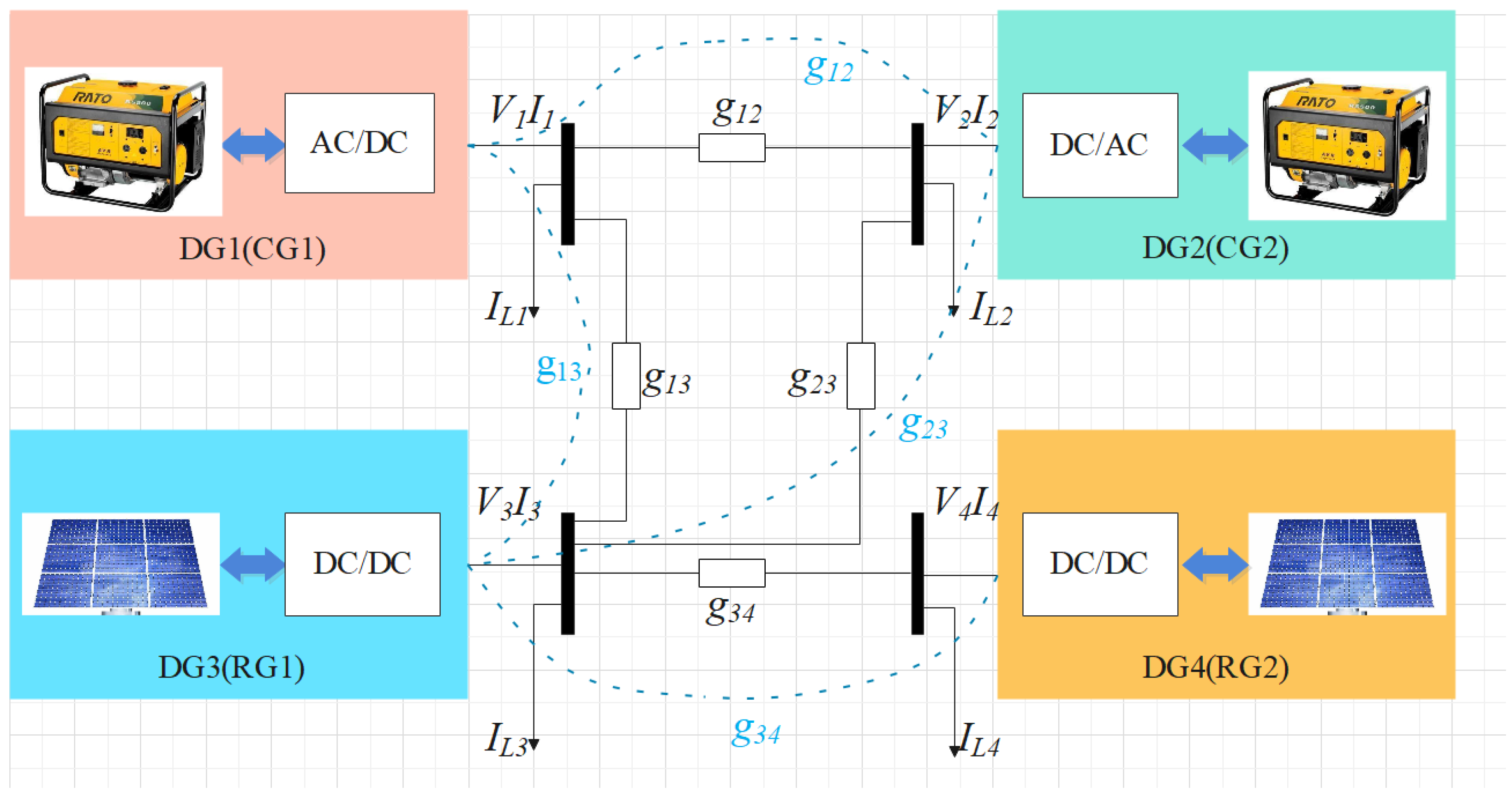
This subsection shows the model of the DC microgrid, which consists of a communication network with a dashed line and an electrical network with a solid line. The overall diagram can be shown in Figure 1.
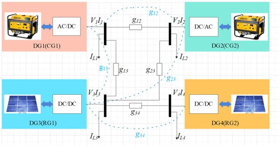
Figure 1.
The overall DC microgrid model description.
From the view of graph theory, a DC microgrid can be simplified as an undirected connected graph , where denotes the buses of DGs consisting of . is the transmission of electric energy in the DC microgrid. Let be the adjacency matrix of , where for , and otherwise. Define , which represents the in-degree of the vertex, where . Let be the Laplacian matrix of .
According to Kirchhoff’s Current Laws, the mathematical model of the circuit in Figure 1 can be expressed as follows:
where , , and represent the voltage, output current, and load current of DG i, respectively.
To simplify the derivation, (1) can be rewritten in the following compact form:
where , , and .
Then, we give the following two assumptions in this paper.
Assumption 1.
The power network of the DC microgrid has the same topology diagram as the communication network.
Assumption 2.
The inductors and capacitors in the circuit do not excessively impact the grid system.
2.2. Electrical Network Model
In general, the generation cost of CG i can be expressed as a quadratic function with respect to power :
where , , and are the cost coefficients.
Similar to the CG i, according to [23], the generation cost of RG i can be approximated by a quadratic function:
where , , and . is the maximum output current of RG i.
Remark 1.
When the system is operating normally, the value of is usually close to 1 p.u. Therefore, it is possible to obtain . So, the generation cost of RG i can be approximated by a quadratic function based on .
The cost functions of CG and RG can be expressed uniformly by (5):
Using the above, consider the following convex optimization problem:
where is the total cost. , , , and denote the lower and upper bounds of bus i current and voltage, respectively.
Assumption 3.
There exists an interior point satisfying , where , and .
3. Distributed Event-Triggered Optimization Algorithm
In this section, a distributed event-triggered optimization algorithm in the discrete time domain is designed. Before designing the algorithm, the equivalent sufficient conditions for the optimal solution of the convex optimization problem (6) are given.
3.1. Convex Optimization Solving Conditions
Define as a project operator that can be denoted as , where denotes a closed convex set.
Lemma 1
([30]). For and , the following inequalities are satisfied:
Lemma 2
where is a user-defined step size. , and .([29]). If Assumption 3 holds, and are optimal solutions to the problem (6) if and only if satisfies
Remark 2.
and denote the fixed points in the mapping introduced by the projection operators and , respectively. It ensures that the objective function achieves optimal values over a specified range of voltages and currents.
3.2. Distributed Event-Triggered Optimization Algorithm
In a real grid system, the bus voltage references are only updated at discrete time instants . Define .
Define the current and voltage error as
where and are the trigger values of and triggered at the kth moment. and can be expressed as follows:
where is the previous trigger moment.
Based on the optimal solution given in (8), the distributed event-triggered optimal control algorithm is proposed as
where is an auxiliary variable. is the internal current control signal. .
Based on the measurement error, the following event-triggering conditions are designed:
where and are non-negative constants.
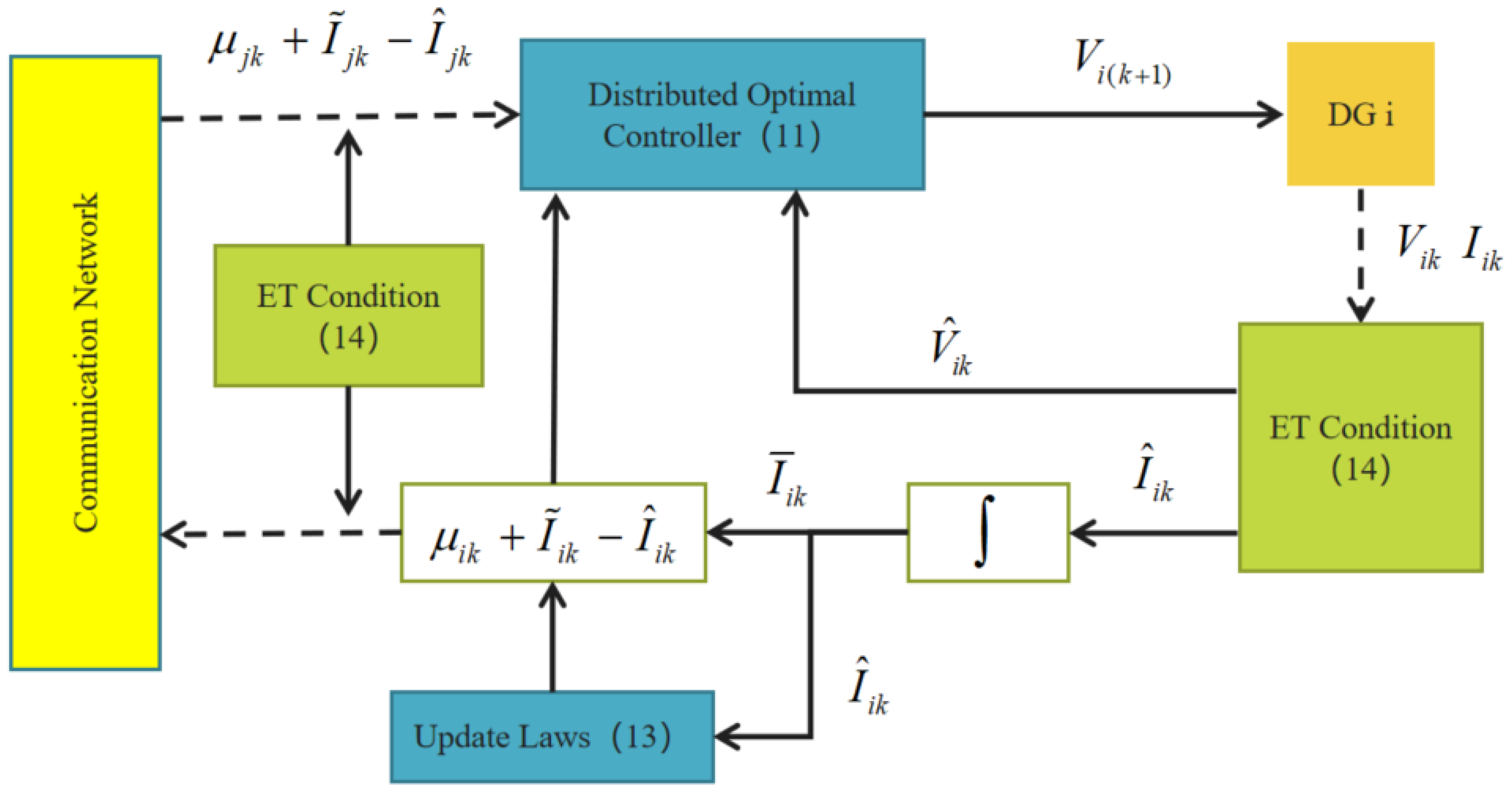
The control framework is shown in Figure 2.
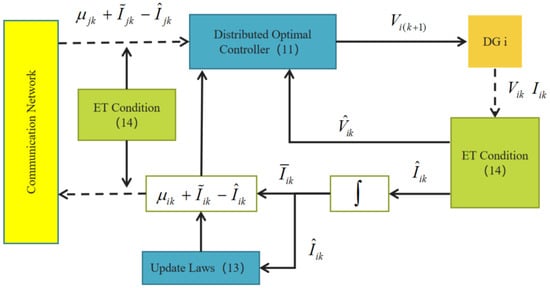
Figure 2.
The system framework of control algorithm for DG i.
Then, the following main proposed theorem can be obtained.
Theorem 1.
Consider the DC microgrid (2) with the proposed distributed event-triggered optimization algorithms (11)–(13) and event-triggered conditions (14). If , the output current and the output voltage will converge asymptotically to the optimal solution of (6). The matrix is represented as follows:
where represents the maximum eigenvalue of matrix Ω. denotes the identity matrix. is a constant.
4. The Convergence and Stability of the Algorithm
To facilitate analysis, Equations (11)–(13) are rewritten in the following form:
Let , , and let .
(1) Define and . Then, the difference of is
Define and . According to Lemma 1, it yields
Substituting (18) into (17), it yields
From Lemma 1 and (7), we have
Consider and . Substituting (10) into (19), (19) can be written as
(2) Let and . Then, it has
Define and . From the inequality in Lemma 1, it can obtain
Then, we can obtain that
From the convexity of , we have
Then, we have
Due to and , then we have
Substituting (23), (24), (25), (26), and (27) into (22) yields
(3) Since , the difference of is therefore
Consider the following Lyapunov function as
Substituting (21), (28), and (29) into (30) yields
From (9) and (31), the following mathematical derivation can be obtained:
Then since , we have
Due to , we then have
Let and substitute (32), (33), and (34) into (31) to yield
Since , then . Therefore, we have
Furthermore, we have
Through the design of the event trigger function, this yields
According to LaSalle invariant set theory, we can obtain
where , and satisfy.
So, and are optimal solutions of (6). Vk and Ik can converge to and .
Based on the above analysis, the proof is completed.
5. Simulation Experiments
In this section, some simulation cases are used to verify the validity of the designed distributed optimal algorithm. The Laplace matrix of the DC microgrid [31] in Figure 1 is
5.1. Parameters Setup
In a DC microgrid, all distributed power sources are connected to the grid through a DC/DC converter and a filter to provide power to the load. The system parameters are given in Table 1 [31], and the controller parameters are given in Table 2.

Table 1.
Parameters for DC microgrid system.
Table 2.
Parameters for event-triggered mechanism.
5.2. Case 1: Constant RG
In the simulation, the load conditions are presented in Table 3, and the constant generation capacities of the RGs were all 1.0 p.u. The experimental results are shown in Figure 3, Figure 4 and Figure 5.
Table 3.
Local loads profiles in Case 1.
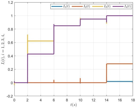
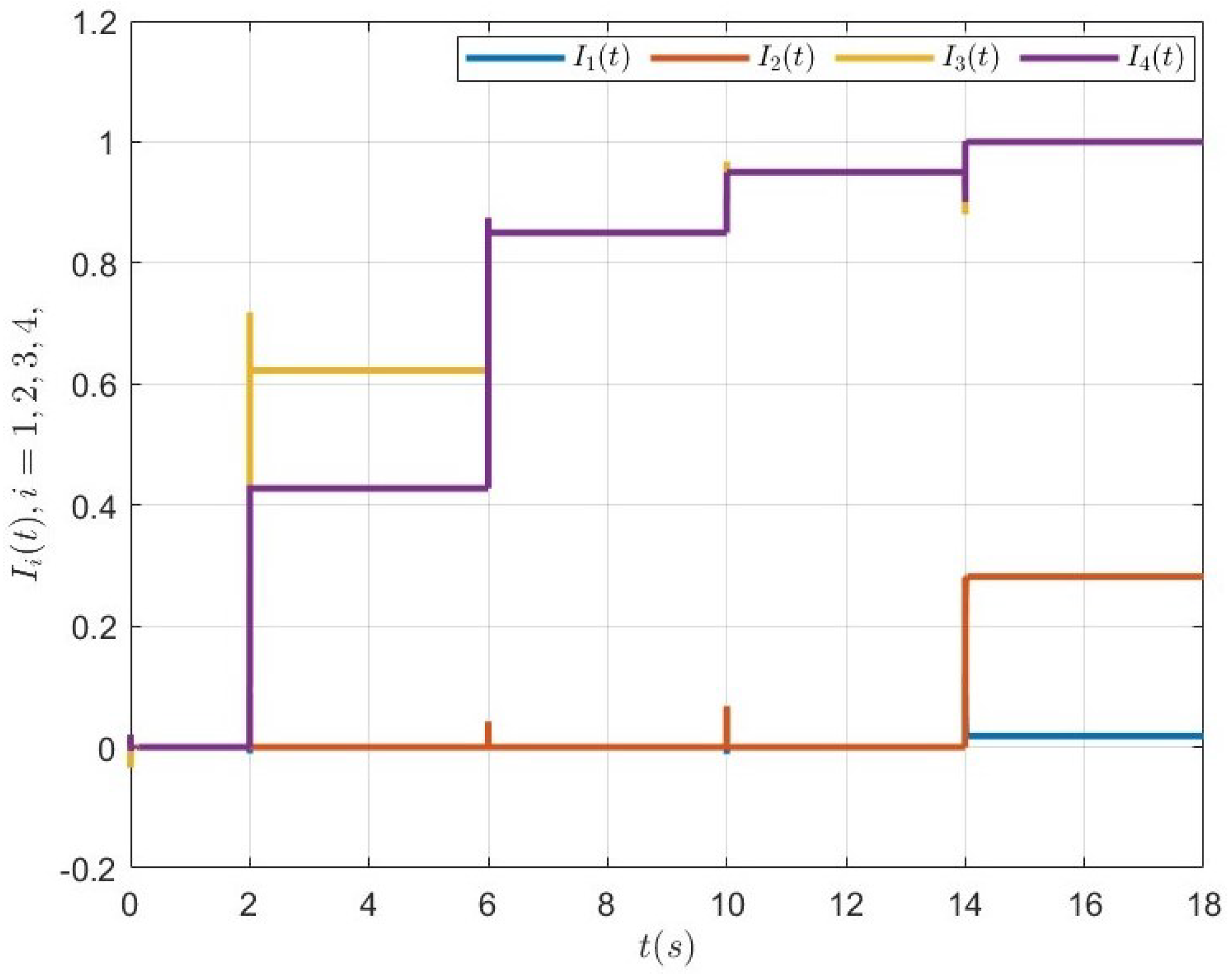
Figure 3.
Trajectories of output currents in case 1.
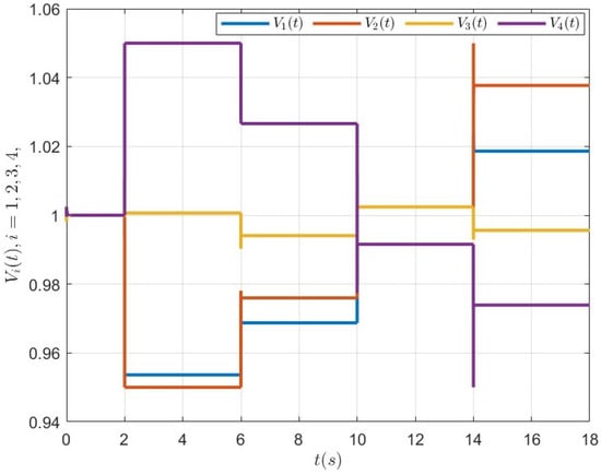
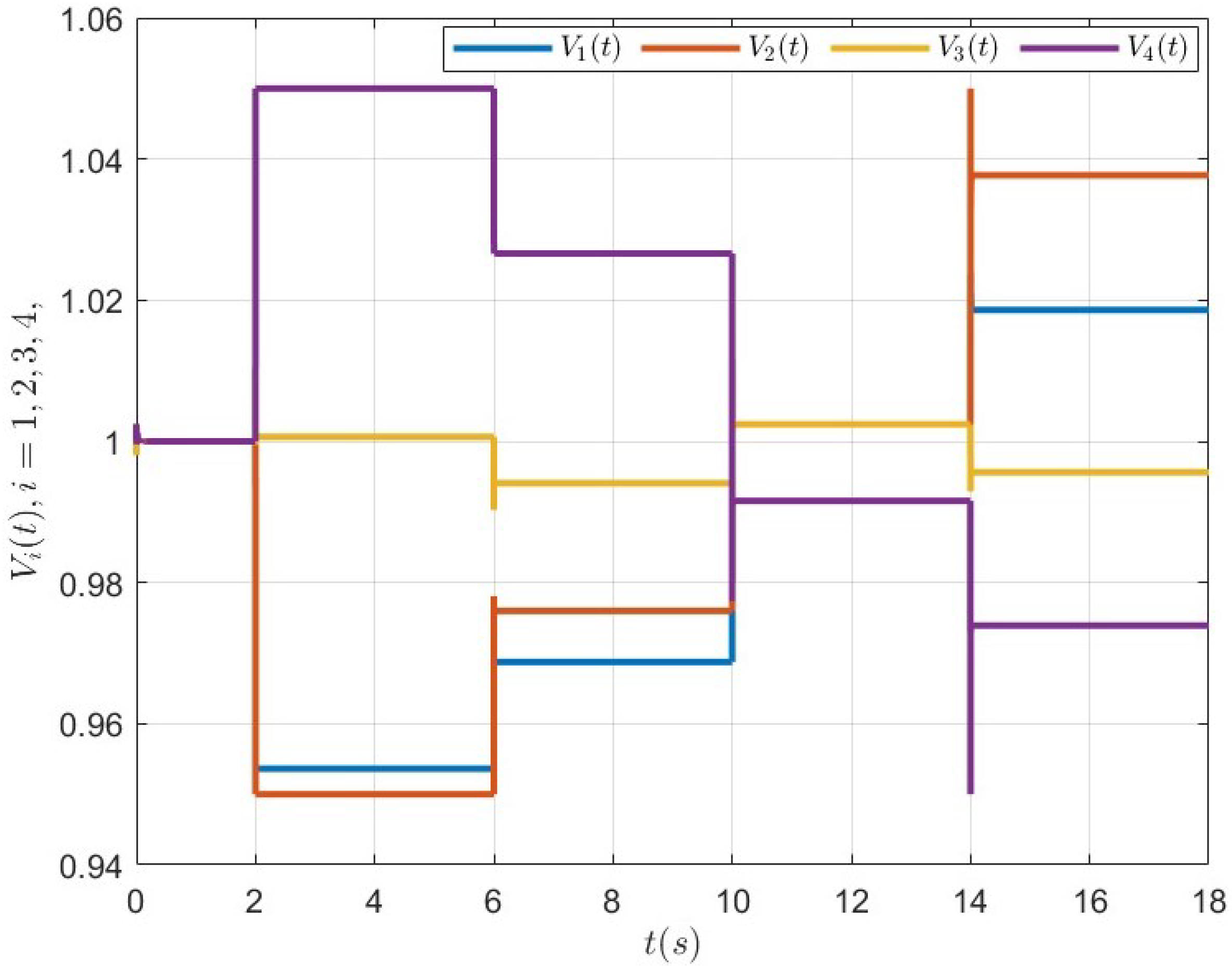
Figure 4.
Trajectories of bus voltages in case 1.
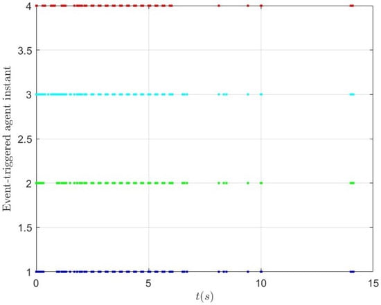
Figure 5.
Event-triggered instants in case 1.
The load demand for case 1 is shown in Table 3. From 0 to 2 s, the load was 0, and the current value was 0 in Figure 3. Between 2 and 6 s, the total load was , which means the combined maximum power generation capacity of RG1 and RG2 is greater than the total demand of all the loads in the DC microgrid system. Therefore, RG1 and RG2 were prioritized to supply power to the loads. As seen in Figure 3, we can clearly see that between 2 and 6 s, only RG1 and RG2 were generating power, and their combined output equaled 1.05. Between 6 and 10 s, the total load demand of the DC microgrid system was 1.7, which is greater than the maximum generation capacity of a single RG but less than the combined maximum capacity of RG1 and RG2. Thus, during this period, the power generation was provided by RG1 and RG2, and they shared it equally. The same situation occurred between 10 and 14 s. From 14 to 18 s, the total load demand of the DC microgrid system was 2.3, which is greater than 2, meaning the combined maximum power generation capacity of RG1 and RG2 was less than the total demand of all loads in the DC microgrid system. Therefore, CG1 and CG2 also started generating power, with a combined output of 0.3. As seen in Figure 3, we can see that between 14 and 18 s, the combined maximum power generation capacity of RG1 and RG2 was 2, and the combined output of CG1 and CG2 was 0.3. These stages of the experiment fully verify the effectiveness of the proposed algorithm: when the combined maximum power generation capacity of renewable energy sources RG1 and RG2 was greater than the total demand of all loads in the DC system, RG1 and RG2 were prioritized to supply power to the loads. When the maximum power generation capacity of renewable energy sources was insufficient to meet the total load demand, the conventional power sources CG1 and CG2 generated power to make up for the shortfall.
As seen in Figure 4, it can be seen that the voltage values of the four DC buses remained near their rated values, ensuring the system’s safety. From Figure 5, it can be concluded that event-triggered control has an excellent control effect and saves communication resources. It is worth noting from Figure 5 that we can observe that whenever the load changed, the number of communications in the system increased in a short period and then gradually decreased. This corresponds to the actual situation: after the load changes, the system error increases, causing the event-triggered function to reach its threshold and trigger information exchange. After some time, the optimization algorithm achieves power distribution, and the event-triggering condition is no longer met, thus reducing the number of communications.
5.3. Case 2: Dynamic RG
In the simulation, we consider the maximum generating capacity of the RG as a linear segmental function with respect to time, whose maximum generating capacity is specifically expressed in the following form:
The required current values on the local load are given in Table 4, and the simulation images are shown in Figure 6, Figure 7, Figure 8 and Figure 9.
Table 4.
Local loads profiles in case 2.

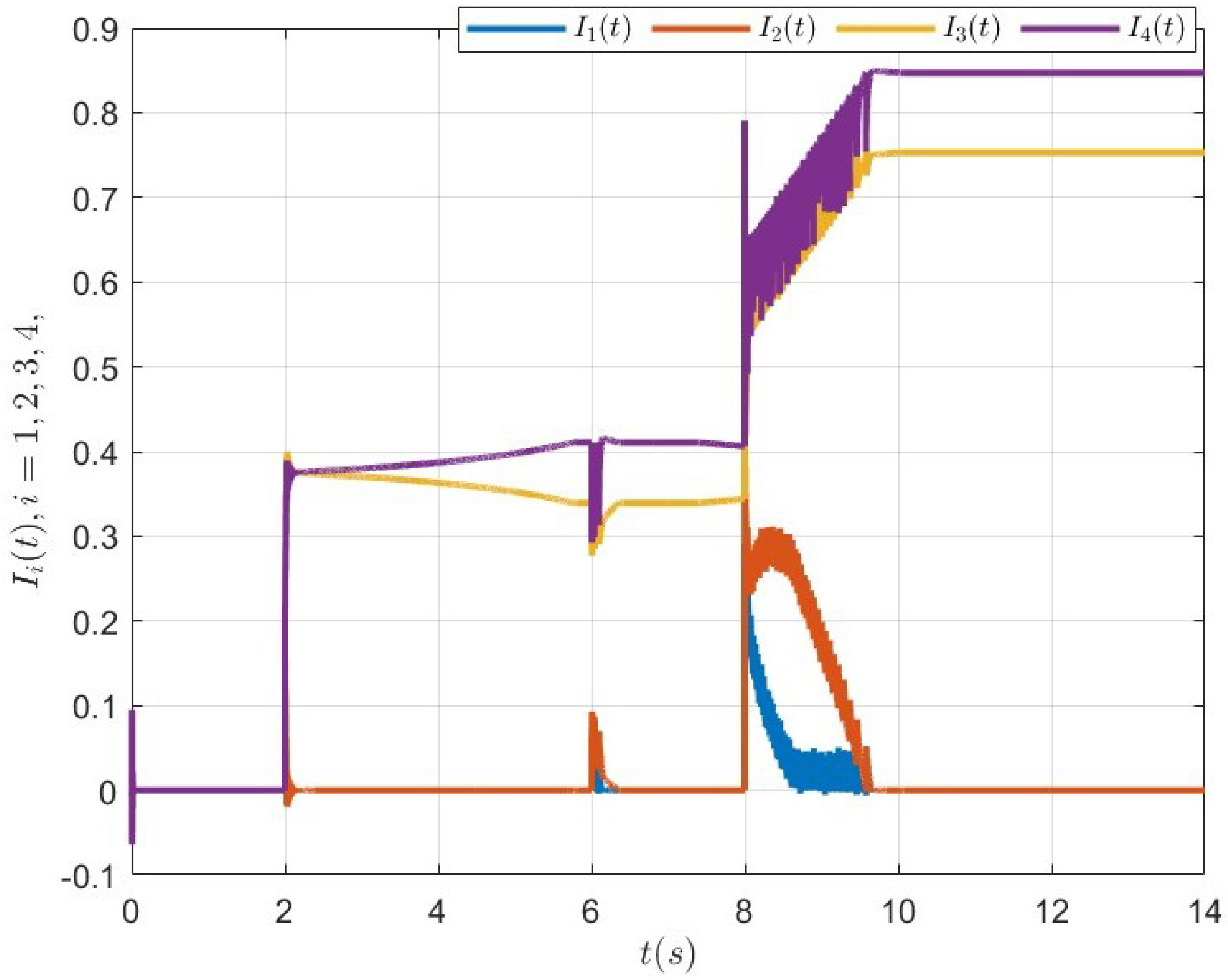
Figure 6.
The results of the output currents.
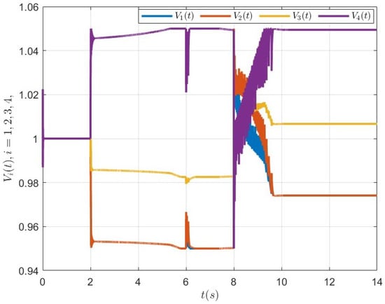
Figure 7.
The results of the bus voltages.
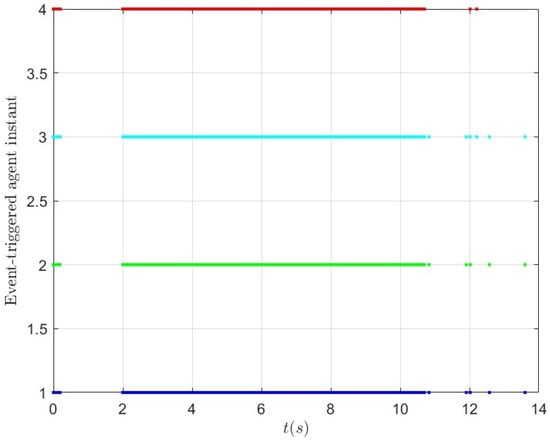
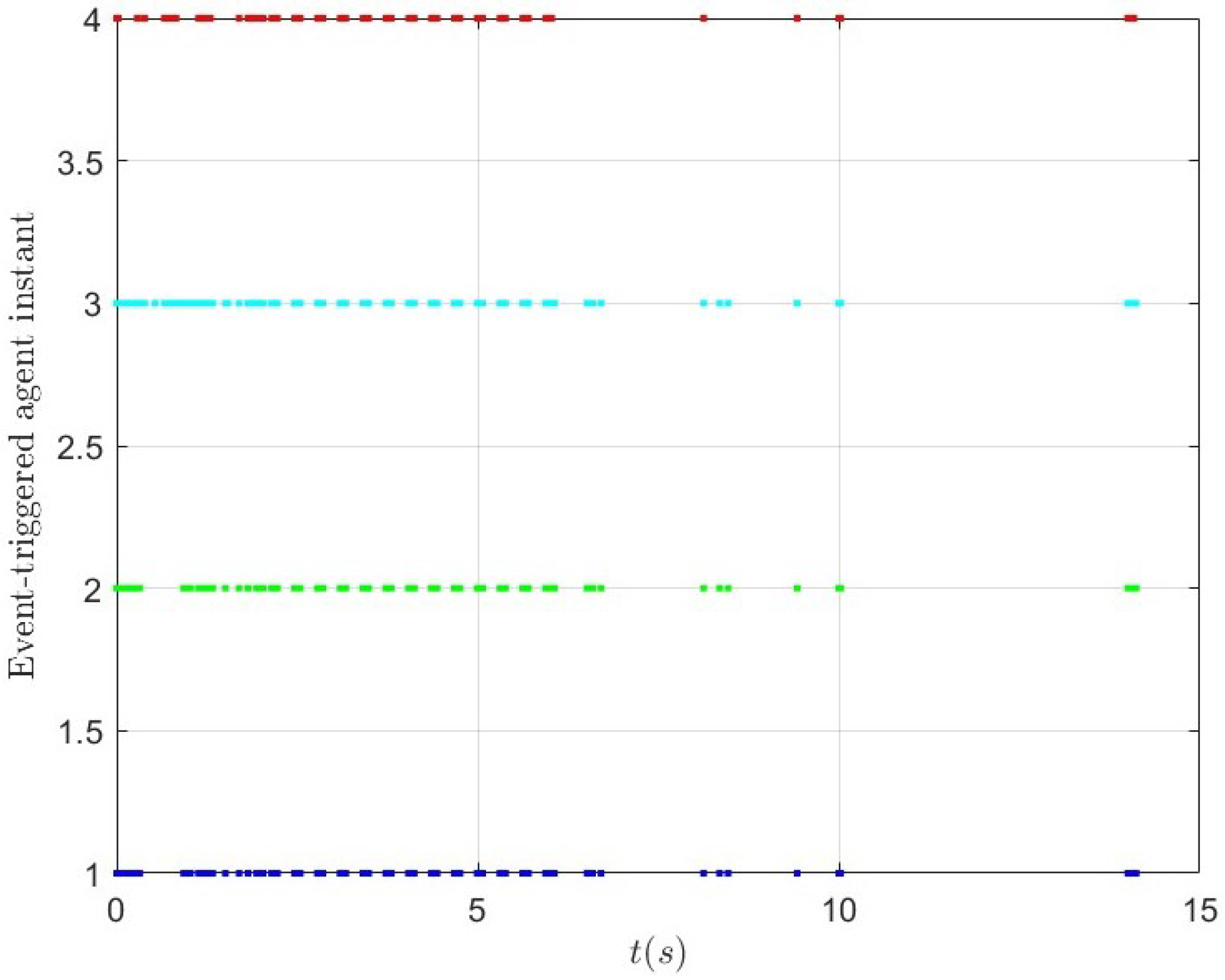
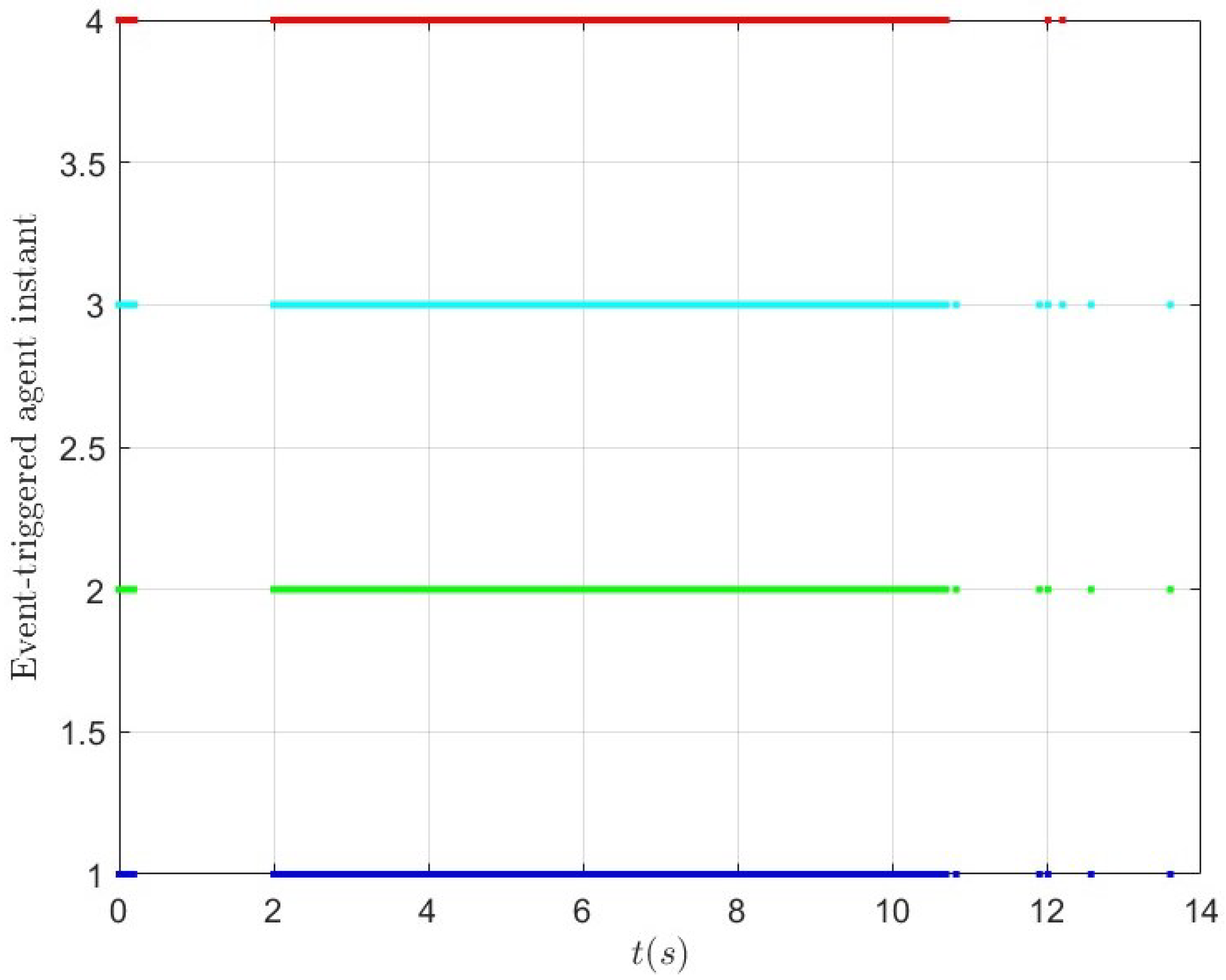
Figure 8.
The results of the event-triggered instants.
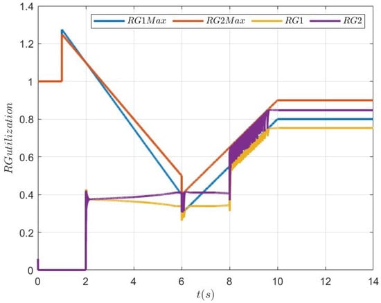
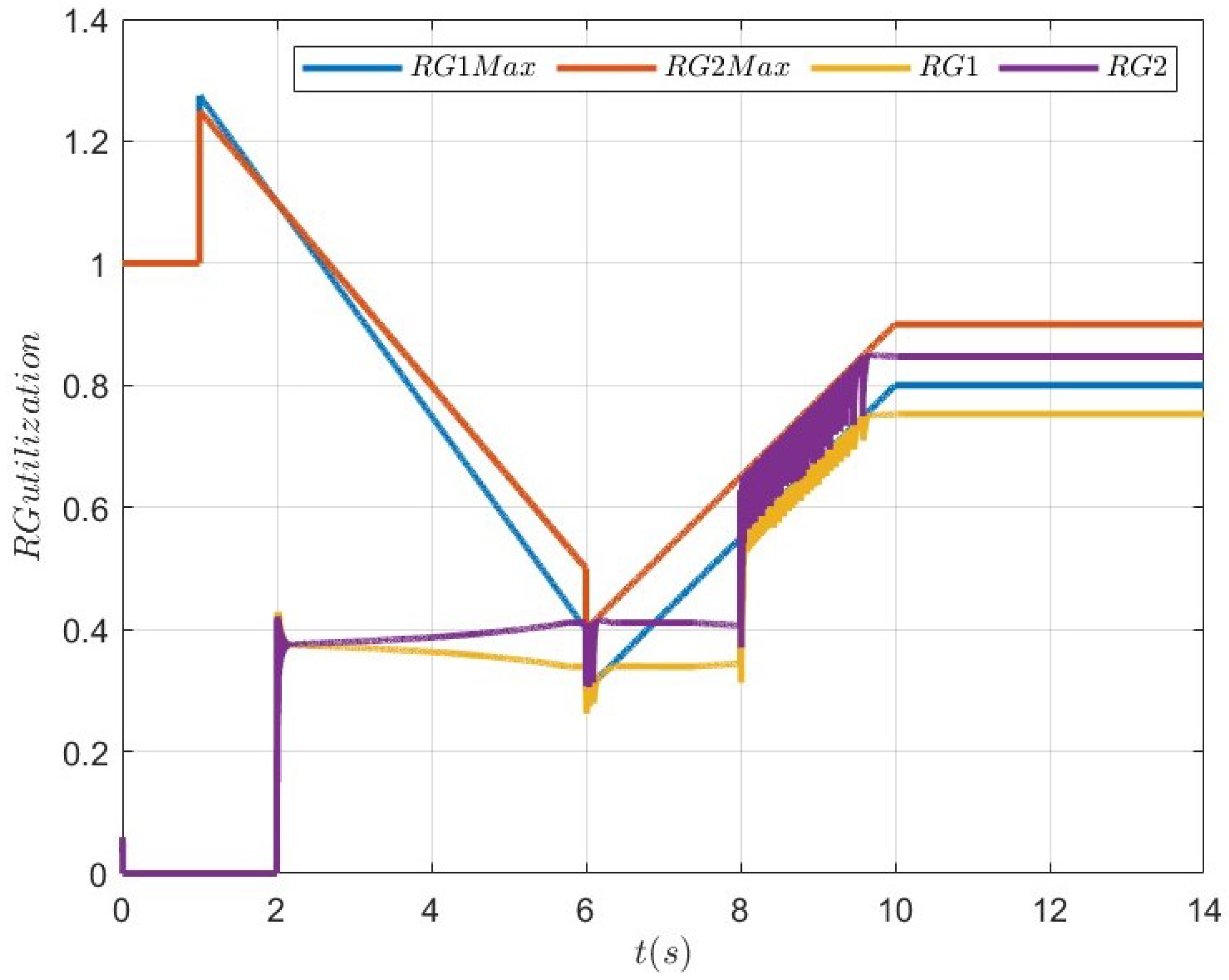
Figure 9.
The results of the renewable energy utilization rate.
It can be seen that Table 4 shows the load demand for case 2. When t was between 0 and 2 s, the load was 0. Figure 6 shows the results of the output current. Similarly, Figure 7 shows the bus voltage results. As seen in Figure 6, the current value was 0. Between 2 and 8 s, the total load was . This process needed to be divided into two stages: 2–6 s and 6–8 s. In the 2–6 s period, the capacities of RG1 and RG2 decreased over time, but the total maximum generation capacity of RG1 and RG2 was greater than the total demand of all loads in the DC system. Therefore, RG1 and RG2 were prioritized to supply power to the loads. In the 6–8 s period, the initial capacities of RG1 and RG2 were 0.3 and 0.4, respectively. The total maximum generation capacity of RG1 and RG2 was less than the total demand of all loads in the DC microgrid DC system, which was 0.75. Therefore, at 6 s, in addition to the RG1 and RG2 generating power, CG1 and CG2 also started generating power to reach a total generation of 0.75. After some time, the maximum capacities of RG1 and RG2 gradually increased, and eventually, their total maximum generation capacity exceeded the total demand of all loads in the DC system. As a result, CG1 and CG2 stopped generating power, and RG1 and RG2 were prioritized to supply power to the loads. When t was between 8 and 14 s, the total load was . This stage was also divided into two parts. When the time was 8 s, the total maximum generation capacity of RG1 and RG2 was . Therefore, at this stage, RG1, RG2, CG1, and CG2 were all generating power to supply the loads, which is clearly visible in the figure. As time progressed, the maximum capacities of RG1 and RG2 gradually increased, and eventually, their total maximum generation capacity exceeded the total demand of all loads in the DC system. Therefore, around 9.7 s, CG1 and CG2 stopped generating power, and RG1 and RG2 supplied power to the loads.
In addition, Figure 8 shows the trigger events of the system under the proposed event-triggered mechanism. As seen in the figure, it is evident that the total communication time of each unit in the DC microgrid system was significantly reduced. It is important to note that between 2 and 10 s, the maximum generation capacity of RG1 and RG2 varied over time. This necessitated the system to adjust the power generation of RG1, RG2, CG1, and CG2 based on the actual maximum generation capacities of RG1 and RG2. Consequently, during this stage, the number of event triggers increased significantly.
Figure 9 shows the maximum and actual capacities of RG1 and RG2. Between 0 and 6 s, the capacities of RG1 and RG2 decreased over time, but their values remained greater than the total demand of the loads. Therefore, we can observe from the figure that the RG1max and RG2max curves were above the RG1 and RG2 curves. During the 6–8 s period, since at s, the capacities of RG1 and RG2 were less than the total load demand, the RG1max and RG2max curves coincided with the RG1 and RG2 curves. After some time, the maximum capacities of RG1 and RG2 gradually increased, and eventually, their total maximum generation capacity exceeded the total demand of all loads in the DC system. The RG1max and RG2max curves rose above the RG1 and RG2 curves again. In the 8–14 s period, the curve changes were similar to those in the 6–8 s period. As seen in the figure, it can be seen that the maximum utilization rates of RG1 and RG2 were less than or equal to 100%, which is consistent with the actual situation.
6. Conclusions and Future Work
Actuators are essential components in modern distributed electric grids and renewable energy network architectures, and they are responsible for executing control actions based on data collected by sensors. They play a critical role in making precise adjustments to various operational parameters, ensuring optimal performance and stability of the system. The paper proposed a new distributed event-triggered optimization algorithm in the discrete time domain to address the EDP of DC microgrids containing renewable energy. The algorithm ensures the maximum energy utilization rate of RGs and the minimum cost of CGs. It also achieves a reasonable power distribution among RGs. Then, the ETC reduces the frequency of communication and current sampling and improves the communication efficiency, as well as the lifetime of the system. Finally, the validity of the optimization algorithm was verified by two different cases, which can show the effectiveness of the proposed control methods. Future work will further study the distributed optimal control of DC microgrids with communication delay and parameter uncertainty. Additionally, practical validation will be conducted by deploying the proposed algorithm in real-world DC microgrid systems to assess its performance under various operational conditions and ensure its robustness and reliability in practical applications.
Author Contributions
Conceptualization, W.S. and Y.H.; methodology, W.S. and Y.H.; software, W.S.; validation, W.S. and X.L.; formal analysis, W.S.; investigation, W.S. and X.L.; resources, Y.H.; data curation, W.S. and X.L.; writing—original draft preparation, W.S. and X.L.; writing—review and editing, Y.H.; visualization, Y.H.; supervision, Y.H.; project administration, Y.H.; funding acquisition, Y.H. All authors have read and agreed to the published version of the manuscript.
Funding
This research received no external funding.
Data Availability Statement
For data requests, please contact the corresponding author for access.
Conflicts of Interest
The authors declare no conflicts of interest.
References
- Pires, V.F.; Pires, A.; Cordeiro, A. DC Microgrids: Benefits, Architectures, Perspectives and Challenges. Energies 2023, 16, 1217. [Google Scholar] [CrossRef]
- Rangarajan, S.S.; Raman, R.; Singh, A.; Shiva, C.K.; Kumar, R.; Sadhu, P.K.; Collins, E.R.; Senjyu, T. DC Microgrids: A Propitious Smart Grid Paradigm for Smart Cities. Smart Cities 2023, 6, 1690–1718. [Google Scholar] [CrossRef]
- Liu, X.-K.; Wang, S.-Q.; Chi, M.; Liu, Z.-W.; Wang, Y.-W. Resilient Secondary Control and Stability Analysis for DC Microgrids Under Mixed Cyber Attacks. IEEE Trans. Ind. Electron. 2024, 71, 1938–1947. [Google Scholar] [CrossRef]
- Veerasamy, V.; Sampath, L.P.; Singh, S.; Nguyen, H.D.; Gooi, H.B. Blockchain-Based Decentralized Frequency Control of Microgrids Using Federated Learning Fractional-Order Recurrent Neural Network. IEEE Trans. Smart Grid 2024, 15, 1089–1102. [Google Scholar] [CrossRef]
- Shafiqurrahman, A.; Yahyaee, S.A.; Sreekumar, P.; Khadkikar, V. A Novel Decentralized Unbalance Load Sharing Approach For Islanded Microgrids. IEEE Trans. Ind. Appl. 2024, 60, 5714–5725. [Google Scholar] [CrossRef]
- Li, S.; Hu, W.; Cao, D.; Hu, J.; Huang, Q.; Chen, Z.; Blaabjerg, F. A Novel MADRL with Spatial-Temporal Pattern Capturing Ability for Robust Decentralized Control of Multiple Microgrids under Anomalous Measurements. IEEE Trans. Sustain. Energy 2024, 15, 1872–1884. [Google Scholar] [CrossRef]
- Mirzaeva, G.; Miller, D. DC and AC Microgrids for Standalone Applications. IEEE Trans. Ind. Appl. 2023, 59, 7908–7918. [Google Scholar] [CrossRef]
- Fan, B.; Peng, J.; Yang, Q.; Liu, W. Distributed Periodic Event-Triggered Algorithm for Current Sharing and Voltage Regulation in DC Microgrids. IEEE Trans. Smart Grid 2020, 11, 577–589. [Google Scholar] [CrossRef]
- Ali, S.; Zheng, Z.; Aillerie, M.; Sawicki, J.-P.; Péra, M.-C.; Hissel, D. A Review of DC Microgrid Energy Management Systems Dedicated to Residential Applications. Energies 2021, 14, 4308. [Google Scholar] [CrossRef]
- Mosayebi, M.; Sadeghzadeh, S.M.; Gheisarnejad, M.; Khooban, M.H. Intelligent and Fast Model-Free Sliding Mode Control for Shipboard DC Microgrids. IEEE Trans. Transp. Electrif. 2021, 7, 1662–1671. [Google Scholar] [CrossRef]
- Zhang, W.; Xu, Y.; Liu, W.; Ferrese, F.; Liu, L. Fully Distributed Coordination of Multiple DFIGs in a Microgrid for Load Sharing. IEEE Trans. Smart Grid 2013, 4, 806–815. [Google Scholar] [CrossRef]
- Wang, S.; Du, M.; Lu, L.; Xing, W.; Sun, K.; Ouyang, M. Multilevel Energy Management of a DC Microgrid Based on Virtual-Battery Model Considering Voltage Regulation and Economic Optimization. IEEE J. Emerg. Sel. Top. Power Electron. 2021, 9, 2881–2895. [Google Scholar] [CrossRef]
- Chen, Y.; Zhang, Z.; Liu, Z.; Zhang, P.; Ding, Q.; Liu, X.; Wang, W. Robust N–k CCUC model considering the fault outage probability of units and transmission lines. IET Gener. Transm. Distrib. 2019, 13, 3782–3791. [Google Scholar] [CrossRef]
- Lasabi, O.; Swanson, A.; Jarvis, L.; Aluko, A. Dynamic Distributed Collaborative Control for Equitable Current Distribution and Voltage Recovery in DC Microgrids. Energies 2023, 16, 6657. [Google Scholar] [CrossRef]
- Zhang, W.; Xu, Y.; Liu, W.; Zang, C.; Yu, H. Distributed Online Optimal Energy Management for Smart Grids. IEEE Trans. Ind. Inform. 2015, 11, 717–727. [Google Scholar] [CrossRef]
- Rahbari-Asr, N.; Zhang, Y.; Chow, M. Consensus-based distributed scheduling for cooperative operation of distributed energy resources and storage devices in smart grids. IET Gener. Transm. Distrib. 2016, 10, 1268–1277. [Google Scholar] [CrossRef]
- Hosseinzadeh, M.; Salmasi, F.R. Fault-Tolerant Supervisory Controller for a Hybrid AC/DC Micro-Grid. IEEE Trans. Smart Grid 2018, 9, 2809–2823. [Google Scholar] [CrossRef]
- Sun, J.; Palade, V.; Wu, X.-J.; Fang, W.; Wang, Z. Solving the Power Economic Dispatch Problem with Generator Constraints by Random Drift Particle Swarm Optimization. IEEE Trans. Ind. Inform. 2014, 10, 222–232. [Google Scholar] [CrossRef]
- Garcés, A. Convex optimization for the optimal power flow on DC distribution systems. Handb. Optim. Electr. Power Distrib. Syst. 2020, 10, 121–137. [Google Scholar]
- Yang, Z.; Xiang, J.; Li, Y. Distributed Consensus Based Supply–Demand Balance Algorithm for Economic Dispatch Problem in a Smart Grid with Switching Graph. IEEE Trans. Ind. Electron. 2017, 64, 1600–1610. [Google Scholar] [CrossRef]
- Chen, G.; Yang, Q. An ADMM-Based Distributed Algorithm for Economic Dispatch in Islanded Microgrids. IEEE Trans. Ind. Inform. 2018, 14, 3892–3903. [Google Scholar] [CrossRef]
- Peng, J.; Fan, B.; Liu, W. Voltage-based distributed optimal control for generation cost minimization and bounded bus voltage regulation in DC microgrids. IEEE Trans. Smart Grid 2021, 12, 106–116. [Google Scholar] [CrossRef]
- Wang, Z.; Wu, W.; Zhang, B. A Distributed Control Method with Minimum Generation Cost for DC Microgrids. IEEE Trans. Energy Convers. 2016, 31, 1462–1470. [Google Scholar] [CrossRef]
- Zhang, Z.; Dou, C.; Yue, D.; Zhang, B.; Xu, S.; Hayat, T.; Alsaedi, A. An Event-Triggered Secondary Control Strategy with Network Delay in Islanded Microgrids. IEEE Syst. J. 2019, 13, 1851–1860. [Google Scholar] [CrossRef]
- Lai, J.; Lu, X.; Monti, A.; De Doncker, R.W. Event-Driven Distributed Active and Reactive Power Dispatch for CCVSI-Based Distributed Generators in AC Microgrids. IEEE Trans. Ind. Appl. 2020, 56, 3125–3136. [Google Scholar] [CrossRef]
- Najafirad, M.J.; Dehkordi, N.M. Distributed event-triggered control of DC microgrids with output saturation constraint. Int. J. Electr. Power Energy Syst. 2023, 148, 936–947. [Google Scholar] [CrossRef]
- Qian, Y.-Y.; Premakumar AV, P.; Wan, Y.; Lin, Z.; Shamash, Y.A.; Davoudi, A. Dynamic Event-Triggered Distributed Secondary Control of DC Microgrids. IEEE Trans. Power Electron. 2022, 37, 10226–10238. [Google Scholar] [CrossRef]
- Shi, M.; Shahidehpour, M.; Zhou, Q.; Chen, X.; Wen, J. Optimal Consensus-Based Event-Triggered Control Strategy for Resilient DC Microgrids. IEEE Trans. Power Syst. 2021, 36, 1807–1818. [Google Scholar] [CrossRef]
- Liu, Q.; Yang, S.; Hong, Y. Constrained Consensus Algorithms with Fixed Step Size for Distributed Convex Optimization Over Multiagent Networks. IEEE Trans. Autom. Control. 2017, 62, 4259–4265. [Google Scholar] [CrossRef]
- Kinderlehrer, D.; Stampacchia, G. An Introduction to Variational Inequalities and Their Applications; SIAM: Philadelphia, PA, USA, 2000. [Google Scholar]
- Fan, Z.; Fan, B.; Liu, W. Distributed Control of DC Microgrids for Optimal Coordination of Conventional and Renewable Generators. IEEE Trans. Smart Grid 2021, 12, 4607–4615. [Google Scholar] [CrossRef]

Disclaimer/Publisher’s Note: The statements, opinions and data contained in all publications are solely those of the individual author(s) and contributor(s) and not of MDPI and/or the editor(s). MDPI and/or the editor(s) disclaim responsibility for any injury to people or property resulting from any ideas, methods, instructions or products referred to in the content. |
© 2024 by the authors. Licensee MDPI, Basel, Switzerland. This article is an open access article distributed under the terms and conditions of the Creative Commons Attribution (CC BY) license (https://creativecommons.org/licenses/by/4.0/).