Article

Robustness Improved Method for Deadbeat Predictive Current Control of PMLSM with Segmented Stators

by
Shijie Gu
,
Peng Leng
,
Qiang Chen
,
Yuxin Jin
,
Jie Li
and
Peichang Yu
*
College of Intelligence Science and Technology, National University of Defense Technology, Changsha 410073, China
*
Author to whom correspondence should be addressed.
These authors contributed to the work equally and should be regarded as co-first authors.
Actuators 2024, 13(8), 300; https://doi.org/10.3390/act13080300 (registering DOI)
Submission received: 11 July 2024 / Revised: 31 July 2024 / Accepted: 5 August 2024 / Published: 6 August 2024
(This article belongs to the Special Issue Power Electronics and Actuators)

Abstract

:
Permanent magnet linear synchronous motors (PMLSMs) with stator segmented structures are widely used in the design of high-power propulsion systems. However, due to the inherent delay and segmented structure of the systems, there are parameter disturbances in the inductance and flux linkage of the motors. This makes the deadbeat predictive current control (DPCC) algorithm for a current loop less robust in the control system, leading to a decrease in control performance. Compensation methods such as compensation by observer and online estimation of parameters, are problematic to apply in practice due to the difficulty of parameter adjustment and the high complexity of the algorithm. In this paper, a robustness-improved incremental DPCC (RII-DPCC) method—which uses incremental DPCC (I-DPCC) to eliminate flux linkage parameters—is proposed. The stability of the current loop was evaluated through zero-pole analysis of the discrete transfer function. Current feedforward was introduced to improve the stability of I-DPCC. The inductance stability range of I-DPCC was increased from 0.8–1.25 times to 0–2 times the actual value, and the theoretical stability range was increased more than 4 times, effectively improving the robustness of the predictive model to flux linkage and inductance parameters. Finally, the effectiveness of the proposed method was verified through numerical simulation and experiment.

1. Introduction

PMLSMs have a high thrust weight ratio, high precision and fast dynamic response [1], and have advantages over induction motors in the design of high-power electromagnetic propulsion systems [2]. In order to solve the problems of high electromagnetic loss caused by excessive phase resistance and inductance under long stroke, the high-capacity requirements of energy storage inverter systems and the low overall operation efficiency caused by large instantaneous driving power, the structure of segmented stators is generally adopted. By dividing the stator winding into several power units, and switching the power supply between sections of the inverter system using the section switch, a better balance of the design cost, operation loss and work efficiency of the electromagnetic propulsion system is achieved [3].
To ensure the dynamic response of the current loop at high speeds, scholars have introduced DPCC in addition to the conventional PI current control. This method makes it easy to adjust parameters and to track the reference current in two control cycles, which realizes the improvement of control bandwidth and dynamic performance. However, conventional DPCC (C-DPCC) is more sensitive to motor parameter disturbances and system delay. When there are mismatches and delays, steady-state errors and current harmonic interference may occur in the current loop, and it may even become unstable in severe cases [4]. Due to the structure of the segmented stator, the stator inductance and mover flux linkage parameters of PMLSM are inevitably mismatched when the rotor crosses the boundary between adjacent segments [5]. In order to reduce the influence of motor parameter mismatch on predictive control performance, it is necessary to improve the C-DPCC algorithm.
Scholars have conducted a great deal of research—generally in three areas—in connection with the robustness of predictive control to parameter mismatch. The first area of research regards parameter mismatch as a disturbance, realizes disturbance compensation through observer, and reduces the dependence on the exact parameters of the model. The disadvantage of this research is that the observer parameters are difficult to adjust, and the complexity of the control system is thus greatly increased. Many scholars regard the parameter mismatch, external disturbances and other factors as aggregate perturbations of the system, and achieve better anti-perturbation performance by designing a sliding mode observer [6,7], an internal mode perturbation observer [8,9], a Luenberger perturbation observer [10,11], etc., for perturbation compensation. The second area of research focuses on online identification of motor parameters and real-time correction of model parameters, such as parameter identification by the parameter adaptive observer [12,13], recursive least-squares-based method [14,15] and inductance extraction method based on a sliding mode perturbation observer [16], etc. However, due to the under rank problem of PMSM [17,18], only part of the parameters can be identified. The third area of research seeks to improve the DPCC algorithm itself [19,20,21], typically by establishing an incremental model, which is able to eliminate the flux linkage parameter to achieve better parameter robustness, but which leads to a smaller stabilization range of the inductance parameter. In [19], a method was proposed to replace the feedback current in the voltage equation with a feedforward current, which broadened the stability domain, but did not achieve full stability. Other research [20] improved the dynamic performance and robustness under heavy load conditions by extending the single step prediction of the traditional DPCC algorithm to multi-step prediction of transient processes. However, multi-step calculations increase the computational complexity. A current error feedforward method combining an inductance correction algorithm was proposed in [21] to improve the robustness of the IPMSM current loop. However, too many coefficients require adjusting, resulting in high complexity in practice.
In order to solve the problems of inherent delay and segmented structure leading to a disturbance of the inductance and flux linkage parameters and degradation of the current loop performance, an I-DPCC algorithm considering delay compensation was proposed on the basis of the C-DPCC algorithm, which eliminates flux linkage in the predictive model. A stable range of inductance for the I-DPCC method was achieved by theoretical analysis of the current loop transfer function. The transfer function of the current loop and the stable range of its inductance parameters considering the feedforward weight factor were analyzed, based on the current feedforward method. The inductance stability range of I-DPCC increased from 0.8–1.25 times to 0–2 times the actual value, and the theoretical stability range increased more than 4 times, effectively improving the robustness of the predictive model while avoiding the complexity of designing observer and identification algorithms. The current integral compensation method was adopted to address the steady-state error caused by parameter disturbances. Finally, the feasibility of the method was verified through simulation and experiments.

2. PMLSM Modeling for Segmented Designs

The stator voltage equation for PMLSM in the dq coordinate system is as follows [22]:
u d = R i d + L d d i d d t ω e L q i q u q = R i q + L q d i q d t + ω e L d i d + ψ f ,
where u d , u q are the dq-axis components of stator voltage; i d , i q are the dq-axis components of stator current; L d , L q are the dq-axis components of stator inductance; R is the stator resistance; ω e is the electric angular velocity; ψ f is the flux linkage of the permanent magnet. For the surface-mounted PMLSM used in this paper, it was taken that L d = L q = L .
To implement the predictive current control algorithm in a digital system, the above stator voltage equation was discretized using the forward Eulerian method. The discretized stator voltage predictive model for PMLSM is described as follows:
u d k = R L T i d k + L T i d k + 1 ω e k L i q k u q k = R L T i q k + L T i q k + 1 + ω e k L i d k + ψ f ,
where T denotes the control period and k denotes the control moment.
The electromagnetic propulsion system targeted in this article adopts a long stator air-core PMLSM structure, and its stator adopts a segmented stator design, as shown in Figure 1.
Considering the stator segmented design and operating conditions, the actual values of PMLSM model parameters R , L , ψ f are inevitably disturbed during operation, which affects the accuracy of the predictive model and causes a decrease in the control performance of the DPCC algorithm [3]. The subscripts   0 in this article represent the nominal values of the motor parameters used in the predictive model. If not, they represent the actual values.

3. Incremental Models for Flux Linkage Perturbation and Delay Optimization

3.1. DPCC with Delay Compensation

The principle of DPCC is that the predicted current at the next moment can track the present reference current, i.e., i d k + 1 = i d r e f k and i q k + 1 = i q r e f k , thus the predicted voltage value at kth moment can be calculated via the predictive model. Through Equation (2), the predictive equation for stator current can be written as:
i d k + 1 = 1 R T L i d k + T L u d k + ω e k T i q k i q k + 1 = 1 R T L i q k + T L u q k ω e k T i d k + T L ψ f .
In controllers such as DSP, a one-step delay compensation of DPCC is required due to the delay caused by the PWM modulation link, sampling link, etc. The reference voltage at the k + 1 th moment should be calculated at the k th moment, i.e., u d k + 1 = u d * k + 1 and u q k + 1 = u q * k + 1 . The stator current at the k + 2 th moment is regarded as the reference current at the kth moment, so that the output current tracks the reference current in two control cycles, i.e., i d k + 2 = i d ref k and i q k + 2 = i q r e f k . A timing diagram of DPCC considering delay compensation is shown in Figure 2.
It is assumed that the electrical angular velocity remains constant during the two adjacent control periods due to the short control period. Therefore, from Equations (2) and (3), the predictive equation of C-DPCC after one-step delay compensation is obtained as:
i d p k + 1 = 1 R 0 T L 0 i d k + T L 0 u d * k + ω e T 0 i q k i q p k + 1 = 1 R 0 T L 0 i q k + T L 0 u q * k ω e T i d k + T L 0 ψ f 0 .
u d * k + 1 = R 0 L 0 T i d p k + 1 + L 0 T i d r e f k ω e L 0 i q p k + 1 u q * k + 1 = R 0 L 0 T i q p k + 1 + L 0 T i q r e f k + ω e L 0 i d p k + 1 + ψ f 0 ,
where nominal value of the predictive model is replaced by true value; i d p k + 1 and i q p k + 1 denotes the one-shot predictive value of the dq-axis currents; u d * k , u q * k and u d * k + 1 , u q * k + 1 denote the output values of dq-axis voltage at the previous and current moments respectively; i d r e f k and i q r e f k denotes the reference value of dq-axis currents.

3.2. IDPCC without Flux Linkage Parameters

It can be seen from C-DPCC predictive equations that the accuracy of three motor parameters affect the control performance. Parametric robustness of the system can be enhanced by constructing an incremental model that eliminates the mover flux linkage term.
By differentiating between adjacent moments, the current predictive equation, which eliminates the flux linkage term and considers one-step delay compensation, can be obtained from Equation (3).
i d k + 1 = 2 R T L i d k 1 R T L i d k 1 + T ω e i q k i q k 1 + T L u d k u d k 1 i q k + 1 = 2 R T L i q k 1 R T L i q k 1 T ω e i d k i d k 1 + T L u q k u q k 1 .
The voltage predictive equation with the elimination of the flux linkage term is similarly obtained from Equation (2) as:
u d k + 1 = u d k + R i d k + 1 i d k ω e L i q k + 1 i q k + L T i d k + 2 2 i d k + 1 + i d k u q k + 1 = u q k + R i q k + 1 i q k + ω e L i d k + 1 i d k + L T i q k + 2 2 i q k + 1 + i q k .
Similar to C-DPCC above, an I-DPCC algorithm with one-step delay compensation can be obtained by Equations (6) and (7). It is noted that I-DPCC does not necessitate flux linkage parameters, thereby eliminating any potential impact of the mismatch of flux linkage parameters on the control performance.

4. Parametric Robustness Improvement of Inductance

4.1. Inductance Stability Analysis of I-DPCC

The impact of parameter inconsistency on the steady-state error of the predictive current model has been examined in [23,24], demonstrating that the mismatch in resistor characteristics in the I-DPCC algorithm exerts a minimal influence on the equilibrium error and stability of the current loop, while the mismatch of the inductance and flux linkage has a more pronounced effect on the current control. The disturbances caused by the flux linkage parameters were eliminated by the incremental model in the preceding section; accordingly, this section focuses on the impact of inductance parameter mismatch on current loop stability.
When PMLSM operates in steady state at constant thrust, it can be assumed that the dq-axis currents reach stabilization, i.e., i d k 1 = i d k and i q k 1 = i q k . Furthermore, considering that the sampling time T is small enough for the cross-coupling terms in the predictive equations to be neglected [25], the dq-axis is completely decoupled in this case, and Equations (6) and (7) can be combined into the following set of simplified equations:
i d q p k + 1 = 2 R T L i d q k 1 R T L i d q k 1 + T L u d q k u d q k 1 ,
T L u d q k + 1 u d q k = i d q k + 2 2 i d q p k + 1 + i d q k + R T L i d q p k + 1 i d q k .
where Equation (8) represents the incremental delay compensation current predictive equation and Equation (9) represents the incremental voltage predictive equation. After substituting the nominal values, the dq-axis decoupled predictive equation can be obtained as:
i ^ d q p k + 1 = 2 R 0 T L 0 i d q k 1 R 0 T L 0 i d q k 1 + T L 0 u d q k u d q k 1 ,
T L 0 u d q * k + 1 u d q * k = i d q r e f k 2 i ^ d q p k + 1 + i d q k + R 0 T L 0 i ^ d q p k + 1 i d q k .
Assuming that the stator voltage is equal to the output voltage, i.e., u d q * = u d q ,. since R 0 has a large order of magnitude difference compared to 1 / L 0 and the sampling time T is small, the term containing R 0 T / L 0 can be ignored and Z-transformed respectively, and the discrete transfer function from the output voltage to the stator current be obtained from Equations (8) and (9) as:
G u i z = i d q z u d q z = T / L z 1 .
Further through Equations (10) and (11), the discrete transfer function from the error of the reference current to the output voltage can be obtained as follows:
G e u z = u d q z i d q r e f z i d q z = L 0 / T · z z 1 z 3 + 2 l 3 z + 2 2 l .
A closed-loop discrete transfer function from the reference current to real stator current can be derived into Equation (14), as can an incremental transfer function block diagram as shown in Figure 3.
G z = i d q z i d q r e f z = l · z z 3 3 1 l z + 2 1 l .
In order to stabilize the current loop, poles of the discrete transfer function should lie within the unit circle. Assuming that the inductance mismatch ratio is l = L 0 / L , which indicates the ratio of the nominal value of the inductance to the true value, it can be used to measure the stability domain of the inductance parameter. Afterwards, the bilinear transformation through the Routh stability criterion can be calculated for the range of values of l under the premise of closed-loop transfer function stabilization:
0.8 < l < 1.25   .
Figure 4 shows the distribution of the closed-loop zero poles with an inductance mismatch ratio of I-DPCC algorithm under steady state operation. It can be seen that the incremental predictive model requires high accuracy for the inductance value, and that I-DPCC will fail to converge when it exceeds this limit. In contrast, the C-DPCC algorithm has a stable range for inductance of 0 < l < 2 [21]. It can be concluded that the I-DPCC reduces the error brought by the flux linkage parameters, but puts higher requirements on the accuracy of the inductance parameters.

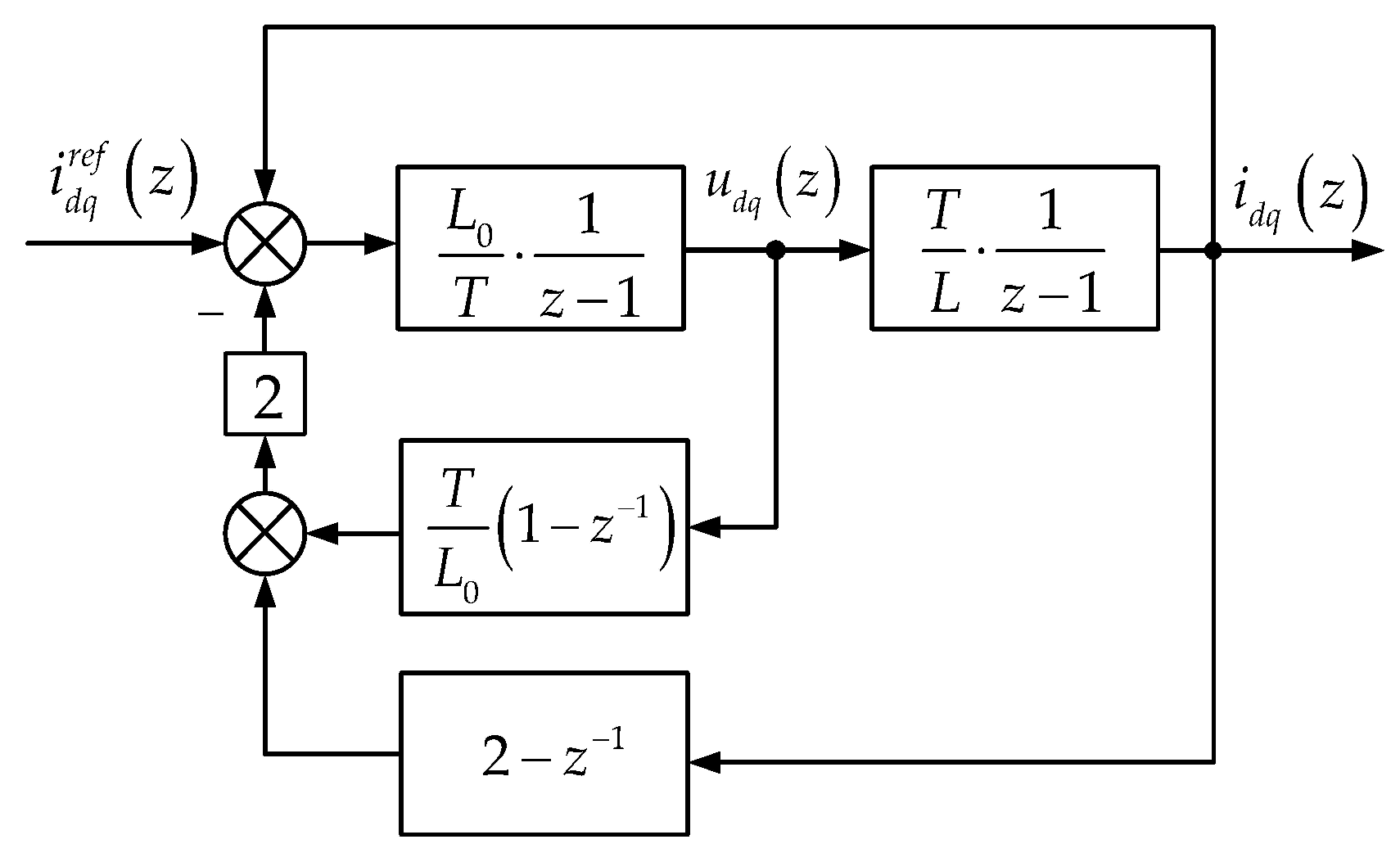
4.2. Principle of RII-DPCC

As may be seen in the analysis in the previous section, I-DPCC imposes high accuracy requirements on the inductance parameters—the error range is limited to about 20%, which greatly reduces the usability of this algorithm. To seek the widening of the stabilization interval of the inductance parameters, this section realizes the widening of the stabilization range of the inductance by introducing a robustness-improved I-DPCC algorithm combining feedforward and feedback currents, and by designing the weighting factors a and b, where a + b = 1 . The improved closed-loop control block diagram is shown in Figure 5, and the improved voltage predictive equation is as follows:
u d * k + 1 = u d * k + R 0 i d r k + 1 i d k + L 0 T i d r e f k 2 i d r k + 1 + i d k ω e L 0 i q r k + 1 i q k u q * k + 1 = u q * k + R 0 i q r k + 1 i q k + L 0 T i q r e f k 2 i q r k + 1 + i q k + ω e L 0 i d r k + 1 i d k i d q r k + 1 = a · i ^ d q p k + 1 + b · i d q r e f k 1 ,
where a one-step predictive current term is calculated as above, but is replaced by a modified delay compensation current term that considers a combination of feedforward and feedback when substituting into the voltage predictive equation.

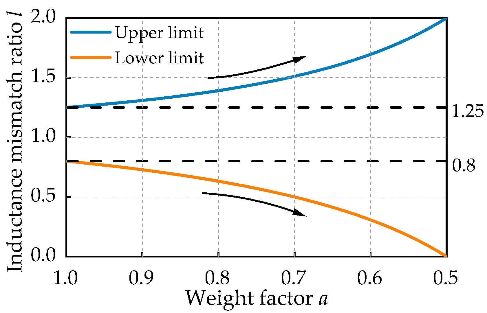
4.3. Stability Analysis of RII-DPCC

The current loop transfer function using a RII-DPCC is analyzed using a similar approach as in Section 4.1. In order to obtain a more concise expression, the derivation is uniformly calculated using a. The improved system transfer function can be obtained as:
G z = l · z 2 + 2 a z 3 + 2 a 2 z 2 + 1 4 a 1 l z + 2 a 1 l .
It can be seen that the introduction of feedforward compensation changes the zero point at the origin of the closed-loop transfer function into an adjustable zero point with a feedforward weight factor, also changing the position of the poles. According to the Routh criterion, the range of the weighting factor a for the stabilization premise of the closed-loop transfer function is calculated as 0.5 a < 1 . This indicates that for RII-DPCC, the feedforward substitution cannot account for more than half of the feedback amount, otherwise the necessary condition for system stabilization will no longer be satisfied.
From the stability criterion, it is further calculated that, with the change of the weight factor a, the sufficient and necessary condition for the value of the inductance mismatch ratio l for the stabilization of the current loop transfer function is shown in Equation (19). The trend of the change is shown in Figure 6.
8 a 4 6 a 1 < l < 1 + 4 a 2 4 a 2 .
Substituting the conditions for the maximum case of the theoretical stability domain into Equation (17), with the introduction of feedforward, a set of pairwise eliminable zero poles at this point in the transfer function can be reduced to:
G z = l z 1 z 2 + l 1 z 1 .
The z 1 term exists in the numerator and denominator of Equation (19). The zero-pole distribution of the improved closed-loop transfer function is shown in Figure 7 and the inductance stability domain is extended to 0 < l < 2 , which is consistent with the theoretical calculation of Equation (19). However, it is worth noting that it is difficult to achieve the accurate zero-pole cancellation of the transfer function in practical engineering applications, which may lead to oscillations in the output of the system. This extreme situation should be avoided as much as possible. For this reason a = 0.55 is considered as the upper limit of the feed-forward weights for the stability verification in the later simulation.

4.4. Steady-State Error Analysis

Substituting Equations (8) and (16) into Equations (9) and (11) respectively, and then calculating the difference, the steady state error is set to be e r r = i d q * k i d q k + 2 , and the steady state error at the k + 2 th moment can be obtained as:
e r r = 2 1 a i d q k 1 + i d q * k 1 2 i d q k + T L 0 T L Δ u d q k + 1 + 2 1 a Δ u d q k ,
where Δ u d q denotes the amount of dq-axis voltage variation between two neighboring moments.
Ignoring the current and voltage ripples and other perturbations, when the PMLSM operates in the steady state, it can be assumed that the dq-axis currents are kept constant, and then the current term in the first half of err always converges to 0, which is not affected by weight a; while the voltage error term in the second half is itself affected by the inductance bias, which cannot be eliminated. In addition, the introduction of feedforward, will additionally introduce a voltage error term for the system which increases with the decrease in the weight a of the voltage error term, which in turn makes the steady state error larger on the basis of I-DPCC.
When a = 0.5, the steady state error reaches the theoretical maximum, which is twice as much as when feedforward compensation is not introduced. For the electromagnetic propulsion system, the importance of the current loop stability is obviously greater than the steady state error under the limit operating conditions. The steady state error can be eliminated by way of integral static differential compensation, which is not specifically derived in this paper.

5. Simulation and Experiment Results

To validate the RII-DPCC algorithm proposed in this paper, numerical simulations are carried out as follows: the propulsion system adopts an air-core PMLSM structure, the system block diagram is shown in Figure 8 and the nominal parameters are shown in Table 1. The inverter adopts an H-bridge cascade topology with a chopping frequency of 1 kHz and a control frequency of 4 kHz to verify the performance of the current control algorithm under constant load.
The experimental part does not use segmented motors, and due to the use of hollow core windings, the end effect is small, so it can be assumed that the actual inductance of the model hardly changes at all. To verify the range of l in the experimental conclusion, we changed the L 0 of the prediction model, which also validates the effectiveness of the method.

5.1. Effect of Delay Compensation on Control Performance

The I-DPCC algorithm is sensitive to delay. When there is no parameter mismatch, the control performance with or without delay compensation is verified by the joint simulation platform. The propulsion system is set to start with a constant q-axis current of 2000 A at 0.1 s, and reduced to 0 at 0.5 s. As shown in Figure 9, when the delay compensation is not considered, the current has a large overshoot at the moment of response. After delay compensation, the overshoot amplitude of the current is reduced by more than 80%, the response is fast and tracking is stable.

5.2. Comparison of Flux Linkage Parameter Robustness

The electromagnetic propulsion system is set to start a 215 kg constant load with a constant q-axis current of 2000 A, and the current is increased by 500 A at 0.2 s and 0.4 s, ultimately reaching 3000 A, to verify the stability and dynamic performance of the current loop. To ensure system safety, the current loop is limited to 3300 A.
As is shown in Figure 10, due to the need for ψ f in the C-DPCC algorithm, steady-state errors are inevitable when there is a mismatch in ψ f . However, the RII-DPCC algorithm can avoid this problem.

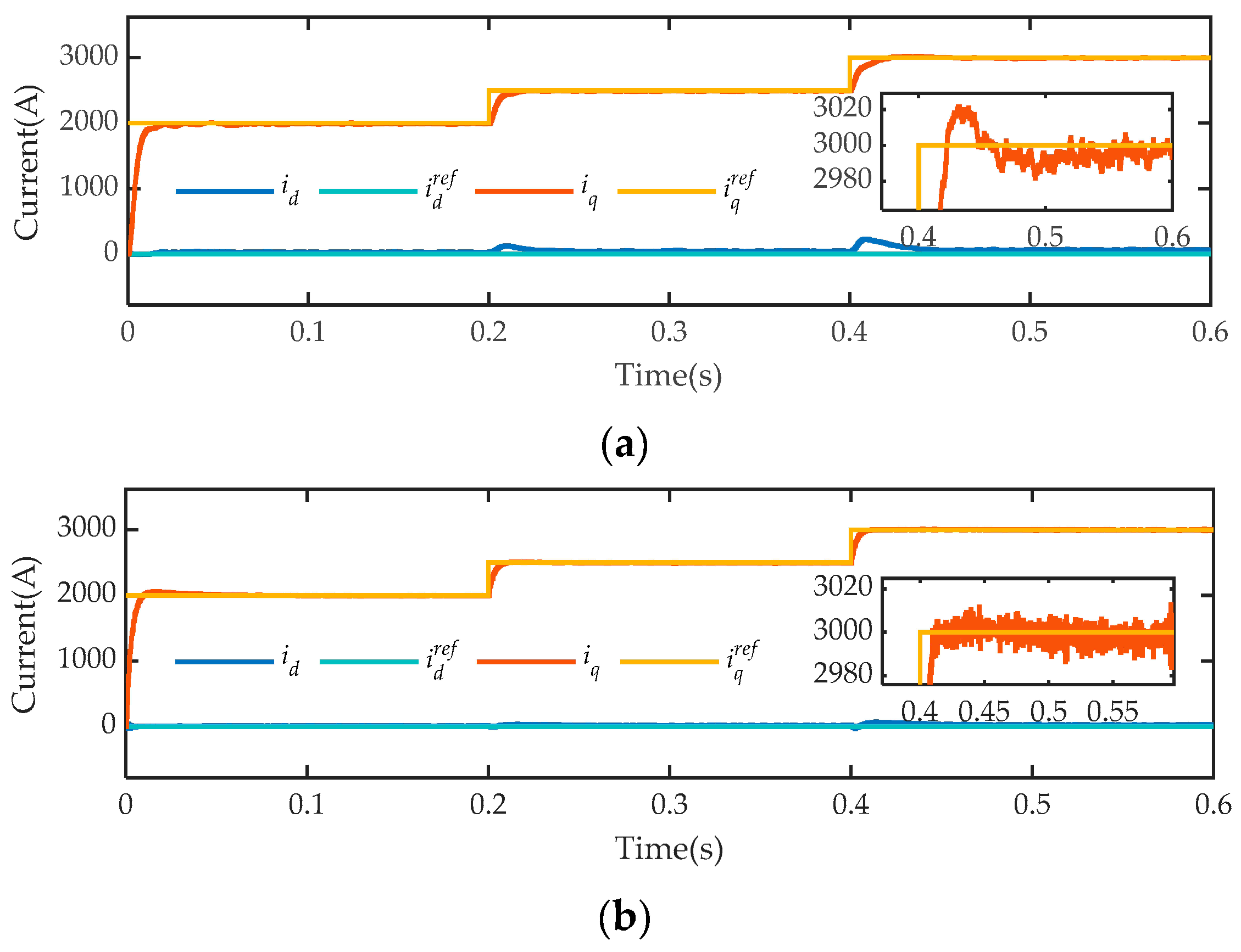
5.3. Comparison of Inductance Parameter Robustness

The operating conditions in this section are consistent with those in the previous section. The nominal inductance parameters of the model are changed separately to verify the improvement in inductance stability of the I-DPCC algorithm before and after improvement. As shown in Figure 11, the dq-axis currents are obtained when the inductance mismatch reaches the actual stable upper and lower limits of the unimproved I-DPCC algorithm.
Figure 11b shows the simulation results of the I-DPCC inductance mismatch calculated in Section 4.1, where the inductance stability domain is expanded only through expected current feedforward and the current loop reconverges. To avoid system oscillation caused by zero pole cancellation of critical stability, a feedforward weight factor is taken. From the simulation results, it can be observed that the addition of feedforward broadens the stability domain of the inductance and again stabilizes the current loop. However, the steady-state error caused by inductance mismatch still exists, which is consistent with the calculation in Section 4.4.
Figure 11c shows the RII-DPCC with integrated static error compensation added on the basis of expected current feedforward. From the simulation results, the current loop achieves zero static error current output while improving the robustness of inductance parameters.
The inductance robustness of RII-DPCC under extreme operating conditions is further verified. As shown in Figure 12, the simulation results of RII-DPCC with inductance mismatch ratios of 0.05 and 2 respectively show that the current loop still achieves stable and fast tracking without static errors. The improved incremental DPCC method improves the inductance stability domain through expected current feedforward, and compensates for steady-state errors through feedback voltage integration. The simulation results show that the stability domain of the current loop inductance has been significantly improved when compared with the results using the traditional incremental method.

5.4. Experimental Results of the Proposed Method

To further verify the proposed method, a scaled-down electromagnetic propulsion platform was constructed, as shown in Figure 13. This platform included an air-core stator winding, permanent magnetic mover, grating positioning system, DC power supply powered by lithium batteries, DC/AC inverter, control board and PC. The main control chip in the control board adopts TMS320F28335 produced by Texas Instruments (Dallas, TX, United States). The current and speed measurement sensors are integrated on the control board and communicate with the PC through UART protocol.
This platform maintains consistency with the simulated system in terms of the design of the inverter, stator winding, and rotor structures, with only specific circuit parameters differing. The specific parameters of the platform are shown in Table 2. The control frequency of the system is consistent with the chopping frequency of the inverter, both at 3 kHz.
Since the influence of flux linkage on the stability of predictive control has been dealt with in other studies, this section will not repeat it, and only the optimization of inductance stability will be experimentally verified. The operating conditions in the experiments are all 50 A current constant thrust, and the running time is 0.6 s.
Figure 14 shows the experimental comparison between I-DPCC and RII-DPCC under constant current. It is observed that the experimental results are consistent with the previous simulation, and the inductance stability domain of I-DPCC is relatively narrow. The current loop exhibits instability when l is less than 0.8 and greater than 1.25. In comparison, the current loop using RII-DPCC can achieve stable tracking without static error in both cases.
As is shown in Figure 15, the current loop stability under several extreme inductance mismatches on the electromagnetic propulsion platform has been verified. Theoretical analysis and simulation show that the inductance stability domain of RII-DPCC is 0 < l < 2 , thus the experimental results verify this conclusion. In two extreme cases, the current loop did not become unstable, but both showed some performance degradation. For example, when l = 0.05 , the response speed of the current loop was slow and there was a significant ripple current; when l = 2 , there was an overshoot peak in the current at the startup moment. When the nominal inductance in the model was changed even further (when l = 2.1 ), there was a divergence phenomenon in the current loop, which is consistent with the previous analysis.

6. Conclusions

This article focused on the robustness of predictive control algorithms to L and ψ f , which is caused by the inherent delay and structure of high-power electromagnetic propulsion systems. Firstly, the impact of delay on predictive algorithms was analyzed. Simulation results showed that the addition of delay compensation can effectively reduce the overshoot of I-DPCC. Under the model proposed in this paper, the overshoot value was reduced by more than 80%. Secondly, the robustness of I-DPCC to ψ f was verified, and, when compared to DPCC that requires ψ f parameters, steady-state errors caused by mismatch could be eliminated. Finally, regarding inductance stability, this article theoretically analyzed the stability range of I-DPCC from the perspective of transfer function, and proposed a feedforward compensation method to improve the stability of I-DPCC. Through transfer function calculation, this method can increase the inductance stability range of I-DPCC from 0.8–1.25 times the actual value to 0–2 times the actual value, and the theoretical stability range more than 4 times. Stable domain measurement was expanded and steady-state error was reduced combined with the integral compensation.
The simulated and experimental results demonstrate the effectiveness of the improved method, enhancing the robustness of the predictive method to L and ψ f , and improving the stability and steady-state error of the system current loop.

Author Contributions

Conceptualization, S.G. and P.L.; methodology, S.G. and P.Y.; software, S.G. and P.L.; validation, P.Y. and P.L.; formal analysis, Q.C.; investigation, Y.J.; resources, P.Y; writing—original draft preparation, S.G.; writing—review and editing, S.G. and P.L.; visualization, Y.J.; supervision, Q.C.; project administration, P.Y.; funding acquisition, J.L. All authors have read and agreed to the published version of the manuscript.

Funding

This work is supported by National Key R&D Program of China [grant number 2016YFB1200601], and the Major Project of Advanced Manufacturing and Automation of Changsha Science and Technology Bureau under grant number kq1804037.

Data Availability Statement

Data are contained within the article.

Conflicts of Interest

The authors declare no conflicts of interest.

References

  1. Tavana, N.R.; Shoulaie, A.; Dinavahi, V. Analytical Modeling and Design Optimization of Linear Synchronous Motor with Stair-Step-Shaped Magnetic Poles for Electromagnetic Launch Applications. IEEE Trans. Plasma Sci. 2012, 40, 519–527. [Google Scholar] [CrossRef]
  2. Tan, Y.; Zhou, D.; Li, J.; Chen, Q.; Jia, Z.; Leng, P.; Liu, M. Dynamic Simulation Analysis of Null-Flux Coil Superconducting Electrodynamic Suspension System. IEEE Trans. Intell. Veh. 2024, 9, 1005–1016. [Google Scholar] [CrossRef]
  3. Wang, M.; Kang, K.; Zhang, C.; Li, L. A Driver and Control Method for Primary Stator Discontinuous Segmented-PMLSM. Symmetry 2021, 13, 2216. [Google Scholar] [CrossRef]
  4. Zhang, Z.; Xu, Q.; Wang, Y. A New Sliding-Mode Observer-Based Deadbeat Predictive Current Control Method for Permanent Magnet Motor Drive. Machines 2024, 12, 297. [Google Scholar] [CrossRef]
  5. Zhang, T.; Mei, X. Research on Detent Force Characteristics of Winding Segmented Permanent Magnet Linear Synchronous Motor Based on Analytical Model. Symmetry 2022, 14, 1049. [Google Scholar] [CrossRef]
  6. Wang, H.; Zhang, G.; Liu, X. Sensorless Control of Surface-Mount Permanent-Magnet Synchronous Motors Based on an Adaptive Super-Twisting Sliding Mode Observer. Mathematics 2024, 12, 2029. [Google Scholar] [CrossRef]
  7. Zhang, X.; Zhao, Z. Model Predictive Control for PMSM Drives with Variable Dead-Zone Time. IEEE Trans. Power Electron. 2021, 36, 10514–10525. [Google Scholar] [CrossRef]
  8. Zhang, R.; Yin, Z.; Du, N.; Liu, J.; Tong, X. Robust Adaptive Current Control of a 1.2-MW Direct-Drive PMSM for Traction Drives Based on Internal Model Control with Disturbance Observer. IEEE Trans. Transp. Electrif. 2021, 7, 1466–1481. [Google Scholar] [CrossRef]
  9. Mohamed, Y.A.-R.I.; El-Saadany, E.F. A Current Control Scheme with an Adaptive Internal Model for Torque Ripple Minimization and Robust Current Regulation in PMSM Drive Systems. IEEE Trans. Energy Convers. 2008, 23, 92–100. [Google Scholar] [CrossRef]
  10. Zhang, P.; Shi, Z.; Yu, B.; Qi, H. Research on a Sensorless ADRC Vector Control Method for a Permanent Magnet Synchronous Motor Based on the Luenberger Observer. Processes 2024, 12, 906. [Google Scholar] [CrossRef]
  11. Andersson, A.; Thiringer, T. Motion Sensorless IPMSM Control Using Linear Moving Horizon Estimation with Luenberger Observer State Feedback. IEEE Trans. Transp. Electrif. 2018, 4, 464–473. [Google Scholar] [CrossRef]
  12. Zhang, L.; Tao, R.; Bai, J.; Zeng, D. An Improved Sliding Mode Model Reference Adaptive System Observer for PMSM Applications. Expert Syst. Appl. 2024, 250, 123907. [Google Scholar] [CrossRef]
  13. Wu, X.; Chen, H.; Liu, B.; Wu, T.; Wang, C.; Huang, S. Improved Deadbeat Predictive Current Control of PMSM Based on a Resistance Adaptive Position Observer. IEEE Trans. Transp. Electrif. 2024. [Google Scholar] [CrossRef]
  14. Naikawadi, K.M.; Patil, S.M.; Kalantri, K.; Dhanvijay, M.R. Comparative Analysis of Features of Online Numerical Methods Used for Parameter Estimation of PMSM. IJPEDS 2022, 13, 2172. [Google Scholar] [CrossRef]
  15. Yuan, T.; Chang, J.; Zhang, Y. Parameter Identification of Permanent Magnet Synchronous Motor with Dynamic Forgetting Factor Based on H∞ Filtering Algorithm. Actuators 2023, 12, 453. [Google Scholar] [CrossRef]
  16. Ahn, H.; Kim, S.; Park, J.; Chung, Y.; Hu, M.; You, K. Adaptive Quick Sliding Mode Reaching Law and Disturbance Observer for Robust PMSM Control Systems. Actuators 2024, 13, 136. [Google Scholar] [CrossRef]
  17. Wang, L.; Zhang, S.; Zhang, C.; Zhou, Y. An Improved Deadbeat Predictive Current Control Based on Parameter Identification for PMSM. IEEE Trans. Transp. Electrif. 2024, 10, 2740–2753. [Google Scholar] [CrossRef]
  18. Rafaq, M.S.; Jung, J.-W. A Comprehensive Review of State-of-the-Art Parameter Estimation Techniques for Permanent Magnet Synchronous Motors in Wide Speed Range. IEEE Trans. Ind. Inf. 2020, 16, 4747–4758. [Google Scholar] [CrossRef]
  19. Zhang, X.; Huang, X. An Incremental Deadbeat Predictive Current Control Method for PMSM with Low Sensitivity to Parameter Variation. In Proceedings of the 2020 International Conference on Electrical Machines (ICEM), Gothenburg, Sweden, 23–26 August 2020; IEEE: New York, NY, USA, 2020; pp. 1060–1066. [Google Scholar]
  20. Liu, Z.; Huang, X.; Hu, Q.; Li, Z.; Jiang, Z.; Yu, Y.; Chen, Z. A Modified Deadbeat Predictive Current Control for Improving Dynamic Performance of PMSM. IEEE Trans. Power Electron. 2022, 37, 14173–14185. [Google Scholar] [CrossRef]
  21. Huang, X.; Hu, Q.; Liu, Z.; Li, W.; Yang, G.; Li, Z. A Robust Deadbeat Predictive Current Control Method for IPMSM. IEEE Trans. Transp. Electrif. 2023. [Google Scholar] [CrossRef]
  22. Blouh, F.; Bezza, M.; El Myasse, I. Modeling and Control of an Aerogenerator Utilizing DFIG and Direct Matrix Converter Technology. In Proceedings of the 2024 4th International Conference on Innovative Research in Applied Science, Engineering and Technology (IRASET), Fez, Morocco, 16–17 May 2024; IEEE: New York, NY, USA, 2024; pp. 1–6. [Google Scholar]
  23. Zhao, M.; Zhang, S.; Li, X.; Zhang, C.; Zhou, Y. Parameter Robust Deadbeat Predictive Current Control for Open-Winding Surface Permanent Magnet Synchronous Motor Drives. IEEE J. Emerg. Sel. Top. Power Electron. 2023, 11, 3117–3126. [Google Scholar] [CrossRef]
  24. Zhang, X.; Zhang, L.; Zhang, Y. Model Predictive Current Control for PMSM Drives with Parameter Robustness Improvement. IEEE Trans. Power Electron. 2019, 34, 1645–1657. [Google Scholar] [CrossRef]
  25. Wang, W.; Xi, X. Current Control Method for PMSM with High Dynamic Performance. In Proceedings of the 2013 International Electric Machines & Drives Conference, Chicago, IL, USA, 12–15 May 2013; IEEE: New York, NY, USA, 2013; pp. 1249–1254. [Google Scholar]
Figure 1. Segmented stator structure for an air-core PMLSM.
Actuators 13 00300 g001
Figure 2. Timing diagram of DPCC with delay compensation.
Actuators 13 00300 g002
Figure 3. Closed-loop control block diagram of I-DPCC.
Actuators 13 00300 g003
Figure 4. Closed-loop zero-pole plot of I-DPCC.
Actuators 13 00300 g004
Figure 5. Closed-loop control block diagram of RII-DPCC.
Actuators 13 00300 g005
Figure 6. Trend of inductance mismatch ratio l with weight factor a.
Actuators 13 00300 g006
Figure 7. Closed-loop zero-pole plot of RII-DPCC when a = 0.5.
Actuators 13 00300 g007
Figure 8. Block diagram of an air-core PMLSM electromagnetic propulsion system using RII-DPCC.
Actuators 13 00300 g008
Figure 9. Comparison of dq-axis current of I-DPCC with and without delay compensation. (a) Not adding delay compensation. (b) Adding delay compensation.
Actuators 13 00300 g009
Figure 10. Comparison of the dq-axis currents at ψ f 0 = 2 ψ f . (a) C-DPCC. (b) RII-DPCC.
Actuators 13 00300 g010
Figure 11. Comparison of the dq-axis current at l = 0.65 and 1.3. (a) I-DPCC with no improvement. (b) RII-DPCC when a = 0.55. (c) RII-DPCC with static error compensation.
Actuators 13 00300 g011
Figure 12. Inductance robustness of RII-DPCC under extreme operating conditions. (a) l = 0.05 . (b) l = 2 .
Actuators 13 00300 g012
Figure 13. Scaled-down experimental platform of PMLSM electromagnetic propulsion system.
Actuators 13 00300 g013
Figure 14. Experimental comparison between I-DPCC and RII-DPCC under constant 50 A current condition. (a) l = 0.7 . (b) l = 1.3.
Actuators 13 00300 g014
Figure 15. Experimental results of RII-DPCC under extreme operating conditions.
Actuators 13 00300 g015
Table 1. Nominal parameters of the PMLSM simulation model.
SymbolParametersValues
UDC bus voltage720 V
R0Nominal stator resistance93.1 mΩ
L0Nominal stator inductance55.6 mH
ψ f 0 Nominal mover flux linkage1.065 Wb
mMover mass215 kg
τPolar distance0.54 m
pPolar pairs3
Table 2. The parameters of the scaled-down electromagnetic propulsion platform.
SymbolParametersValues
UDC bus voltage550 V
R0Nominal stator resistance12.64 mΩ
L0Nominal stator inductance22.2 mH
ψ f 0 Nominal mover flux linkage0.1717 Wb
mMover mass50 kg
τPolar distance0.27 m
pPolar pairs2
Disclaimer/Publisher’s Note: The statements, opinions and data contained in all publications are solely those of the individual author(s) and contributor(s) and not of MDPI and/or the editor(s). MDPI and/or the editor(s) disclaim responsibility for any injury to people or property resulting from any ideas, methods, instructions or products referred to in the content.

