Article

A Reliable and Efficient I-f Startup Method of Sensorless Ultra-High-Speed SPMSM for Fuel Cell Air Compressors

by
Jilei Xing
1,
Yao Xu
2,*,
Junzhi Zhang
1,
Yongshen Li
2 and
Xiongwei Jiang
2
1
School of Vehicle and Mobility, Tsinghua University, Beijing 100084, China
2
School of Mechanical Engineering, Beijing Institute of Technology, Beijing 100081, China
*
Author to whom correspondence should be addressed.
Actuators 2024, 13(6), 203; https://doi.org/10.3390/act13060203
Submission received: 25 April 2024 / Revised: 24 May 2024 / Accepted: 27 May 2024 / Published: 29 May 2024
(This article belongs to the Special Issue Power Electronics and Actuators)

Abstract

:
Extended back electromotive force (EEMF)-based position sensorless field-oriented control (FOC) is widely utilized for ultra-high-speed surface-mounted permanent magnet synchronous motors (UHS-SPMSMs) driven fuel cell air compressors in medium-high speed applications. Unfortunately, the estimated position is imprecise due to too small EEMF under low speed operation. Hence, current-to-frequency (I-f) control is more suitable for startup. Conventional I-f methods rarely achieve the tradeoff between startup acceleration and load capacity, and the transition to sensorless FOC is mostly realized in the constant-speed stage, which is unacceptable for UHS-SPMSM considering the critical requirement of startup time. In this article, a new closed-loop I-f control approach is proposed to achieve fast and efficient startup. The frequency of reference current vector is corrected automatically based on the active power and the real-time motor torque, which contributes to damping effect for startup reliability. Moreover, an amplitude compensator of reference current vector is designed based on the reactive power, ensuring the maximum torque per ampere operation and higher efficiency. Furthermore, the speed PI controller is enhanced by variable bandwidth design for smoother sensorless transition. These theoretical advantages are validated through experiments with a 550 V, 35 kW UHS-SPMSM. The experimental results demonstrated the enhanced startup performance compared with conventional I-f control.

1. Introduction

Due to high efficiency, high power density, and stable rotor structural strength [1,2], ultra-high-speed surface-mounted permanent magnet synchronous motors (UHS-SPMSMs) are being widely used to drive fuel cell air compressors [3,4,5], which in turn provide pressurized air to fuel cell stacks to ensure the power output demand and energy conversion efficiency of hydrogen fuel cell vehicles. UHS-SPMSMs and centrifugal compressors are integrated as the overall compressor system, whose rational speed is typically capable of 100 kr/min and above. Therefore, the mechanical rotor position sensor is replaced by position sensorless control technology in consideration of installation space and reliability, which also reduces maintenance cost.
For medium–high speed applications of UHS-SPMSM, the most commonly used position sensorless methods are based on back electromotive force (EMF) estimation, including the use of sliding mode observer [6,7], extended Kalman filter [8], extended state observer [9], etc. Unfortunately, the EMF is too small to be estimated accurately during low speed operation. For zero–low speed applications of UHS-SPMSM, the typical high frequency signal injection (HFSI) methods [10,11] will no longer be applicable considering the lack of motor saliency due to the equal dq-axes inductances, and the high-frequency noise and torque fluctuations of HFSI are undesirable. The rotor of UHS-SPMSM is carried by a self-acting gas bearing, in which the fluid film is formed by viscous shear forces resulting from the relative motion of journal and bushing under rotation [12]. Therefore, UHS-SPMSM needs to be started rapidly from standstill to a certain speed to ensure the normal performance of gas bearing, and UHS-SPMSM is generally designed with a minimum operating speed (i.e., idle speed) ranging from 20,000 r/min to 30,000 r/min. Under these requirements, the UHS-SPMSM do not operate at ultra-low speed except during startup. Preferably, an uncomplicated yet effective startup strategy, characterized by high dynamic performance, is more advantageous than HFSI methods for expediting the UHS-SPMSM to a speed conducive to accurate EMF estimation.
Voltage-to-frequency (V/f) control has been employed for the startup and speed regulation of UHS-SPMSM owing to its straightforward configuration and reduced number of control loops, including the open-loop optimal V/f control with design consideration to the stator resistance [13], and the closed-loop V/f control with correction of the voltage amplitude and phase [14]. Owing to uncontrollable current and torque ripple, open-loop V/f control is gradually replaced by closed-loop V/f control. In [15], correction loops are designed based on d-axis current error with integrated maximum torque per ampere (MTPA) block, which guarantees good dynamic performance especially at a very low speed. Additionally, a closed-loop V/f control is realized in the voltage vector plane [16]. However, the algorithm complexity increases similar to sensorless field-oriented control (FOC) due to load angle calculation in [15] and rotor position and speed estimation in [16], respectively. In summary, the V/f control has insufficient with-load startup ability, and the control accuracy and efficiency are limited in the medium–high speed range compared with FOC. Therefore, the V/f control is not recommended for the UHS-SPMSM used in hydrogen fuel cell vehicles.
In contrast, another simple and effective startup strategy known as the current-to-frequency (I-f) control is more widely used for the startup of UHS-SPMSM because of its advantages of strong robustness with controllable current loop. The UHS-SPMSM does not always start successfully under open-loop I-f control [17] due to large speed oscillation during the startup stage [18]. The inherent speed oscillation can be suppressed by correcting the frequency of the reference current vector based on active power fluctuation [19]. Meanwhile, with a summary of the change law of the fluctuation amplitude and frequency of torque angle with the motor parameters and the reference current vector [20], the method proposed in [19] can be adaptively designed. Additionally, any signal reflecting speed or torque perturbation can be used to obtain the frequency correction value [21], such as the power factor angle, the calculated torque current, the estimated electromagnetic torque [22], etc. In combination with adaptive back-stepping control [23], fully unknown parameters of SPMSM are able to be estimated accurately, ensuring the effectiveness of I-f control on variation of load and motor parameters.
The reference torque of UHS-SPMSM with conventional I-f startup method far exceeds actual load torque, leading to low motor efficiency. Although adjusting the amplitude of the reference current vector based on reactive power [24,25] and based on power factor [26] can actualize id = 0 control to enhance efficiency; this is only realized after the motor speed remains constant. The implementation mode is not applicable for UHS-SPMSM, which needs to complete the transition of the I-f control to EMF-based sensorless control during acceleration process to ensure the dynamic performance and high efficiency of the startup. In [27], variable reference current vector position is designed in the current compensation loop to avoid large transients. However, additional estimated rotor position is needed from EMF-based method. Moreover, the frequency ramp slope of the reference current vector can be dynamically adjusted during motor acceleration using an angle controller [24] or a torque controller [28].The load torque of UHS-SPMSM increases approximately quadratically in terms of the motor speed. In order to prevent the demand torque from exceeding the maximum output torque, the frequency ramp slope needs to be gradually reduced as a result of the dynamic adjustments, which significantly deteriorates the dynamic performance of UHS-SPMSM startup.
The overall requirement of the UHS-SPMSM startup process is high dynamic response with high efficiency. Considering that the frequency ramp slope cannot be set too high for avoiding startup failure, the transition speed from I-f control to sensorless FOC should be set as small as possible. Meanwhile, a smooth transition with a reduced convergence time and speed fluctuations needs to be addressed. The method proposed in [29] of adjusting the initial value of the integrator of the PI controller of the speed loop and current loop can reduce the speed fluctuations. The design of variable decreasing step size of reference current can contribute positively to reducing the transition time [17]. To improve the stability of the transition process, a feedback regulator is designed [30] to automatically adjust the reference current based on the position difference. However, merely with consideration of the constant speed operation, the above I-f control strategies have neglected the transition process during the motor acceleration, where the load torque increases apace in UHS-SPMSM application. The prevailing transition strategies, including the reduction of reference current [31], an adaptive transition algorithm [32], weighted processing method [33], and a first-order lag compensator of position [34], have hitherto placed insufficient emphasis on evaluating the performance of the I-f control preceding the transition.
The novelty in this article, as an extension of the conventional I-f control, is to propose a closed-loop I-f startup strategy with transition enhancement applicable to UHS-SPMSM to achieve a fast, efficient, and stable startup process, which is summarized as:
(1)
The speed convergence performance can be effectively improved by correcting the frequency of reference current vector adaptively based on not only the instantaneous active power but also the real-time motor torque, which reduces speed fluctuations distinctly.
(2)
The amplitude of reference current vector is compensated dynamically during speedup stage instead of during a constant speed stage, which is the basic requirement and distinctiveness for the UHS-SPMSM. Therefore, the reference startup torque can be reduced with improved efficiency under the premise of guaranteeing the startup rapidity.
(3)
The transition process to EMF-based sensorless FOC can be enhanced by designing a bandwidth-variable regulating scheme of speed loop PI controller, which achieves low transitional speed fluctuation. Moreover, the designed scheme can ensure high control stability over rated motor speed, compared with fixed-gain speed loop PI controller.
(4)
To the best of our knowledge, this is the first time that an innovative closed-loop I-f startup strategy is used for UHS-SPMSM startup, especially for driving fuel cell air compressors.
The rest of this article is organized as follows. Section 2 describes the mathematical model of UHS-SPMSM under I-f control. The stability performance of the conventional I-f startup strategy is analyzed in Section 3. Section 4 elaborates on the proposed closed-loop I-f startup strategy with transition enhancement. In Section 5, the effectiveness of the proposed method is verified by bench experiments with a 35 kW (at 95 kr/min) UHS-SPMSM. Finally, the paper is concluded in Section 6.

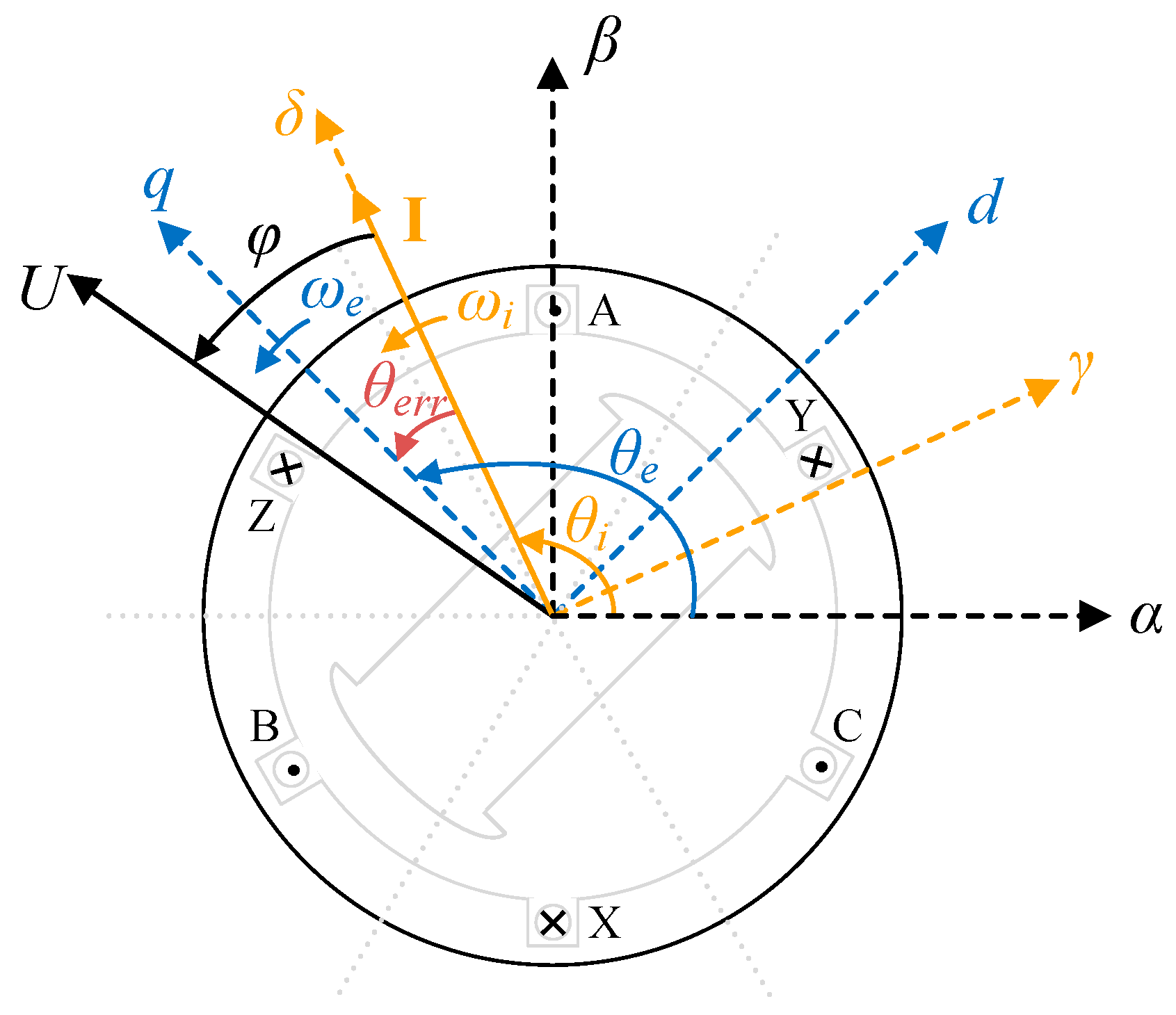
2. Mathematical UHS-SPMSM Model with I-f Control

Due to unknown actual rotor position information during I-f control, the actual d-q reference coordinate frame is also undetermined. Therefore, in order to analyze the characteristics of the controllable current vector, a γ-δ reference coordinate frame is introduced, in which the δ-axis is aligned with the current vector I, as shown in Figure 1. The angles from α-axis to δ-axis and to q-axis are referred to as θi and θe, respectively. The angle error between θi and θe is denoted as θerr = θeθi. The frequencies ωi and ωe denote angular velocities of current vector and rotor, respectively. φ is the angle between the voltage vector U and the current vector. Without loss of generality, the UHS-SPMSM voltage mathematical model [24] in the γ-δ reference coordinate frame can be expressed as:
u γ = R s i γ + L d d d t i γ ω i L q i δ ω e φ f sin θ e r r u δ = R s i δ + L q d d t i δ + ω i L d i γ + ω e φ f cos θ e r r
where uγ, uδ, iγ, and iδ denote the voltages and currents in the γ-δ reference coordinate frame, respectively. Rs, φf, Ld, and Lq denote stator resistance, rotor permanent magnet flux linkage, and d- and q-axis inductances, respectively. The condition Ld = Lq holds throughout this article for the studied UHS-SPMSM. ωe denotes the motor electrical frequency.
Considering that iγ = 0, (1) can be rewritten as:
u γ = ω i L q i δ ω e φ f sin θ e r r u δ = R s i δ + L q d d t i δ + ω e φ f cos θ e r r
The frequency error between ωi and ωe can be obtained from the derivative of angle error.
Δ ω = ω e ω i = d d t θ e r r = d d t ( θ e θ i )
In addition, the UHS-SPMSM electromagnetic torque [24] can be expressed by the current vector amplitude Im and angle θerr as follows with Ld = Lq.
T e = 1.5 n p i q [ φ f + ( L d L q ) i d ] = 1.5 n p φ f I m cos θ e r r
where np denotes the number of pole pairs.
Therefore, the motion equation [24] of UHS-SPMSM is expressed as:
J d ω m d t = T e T L B ω m
where ωm = ωe/np is the rotor mechanical frequency. J is the motor inertia, B is the damping coefficient, and TL denotes the load torque.

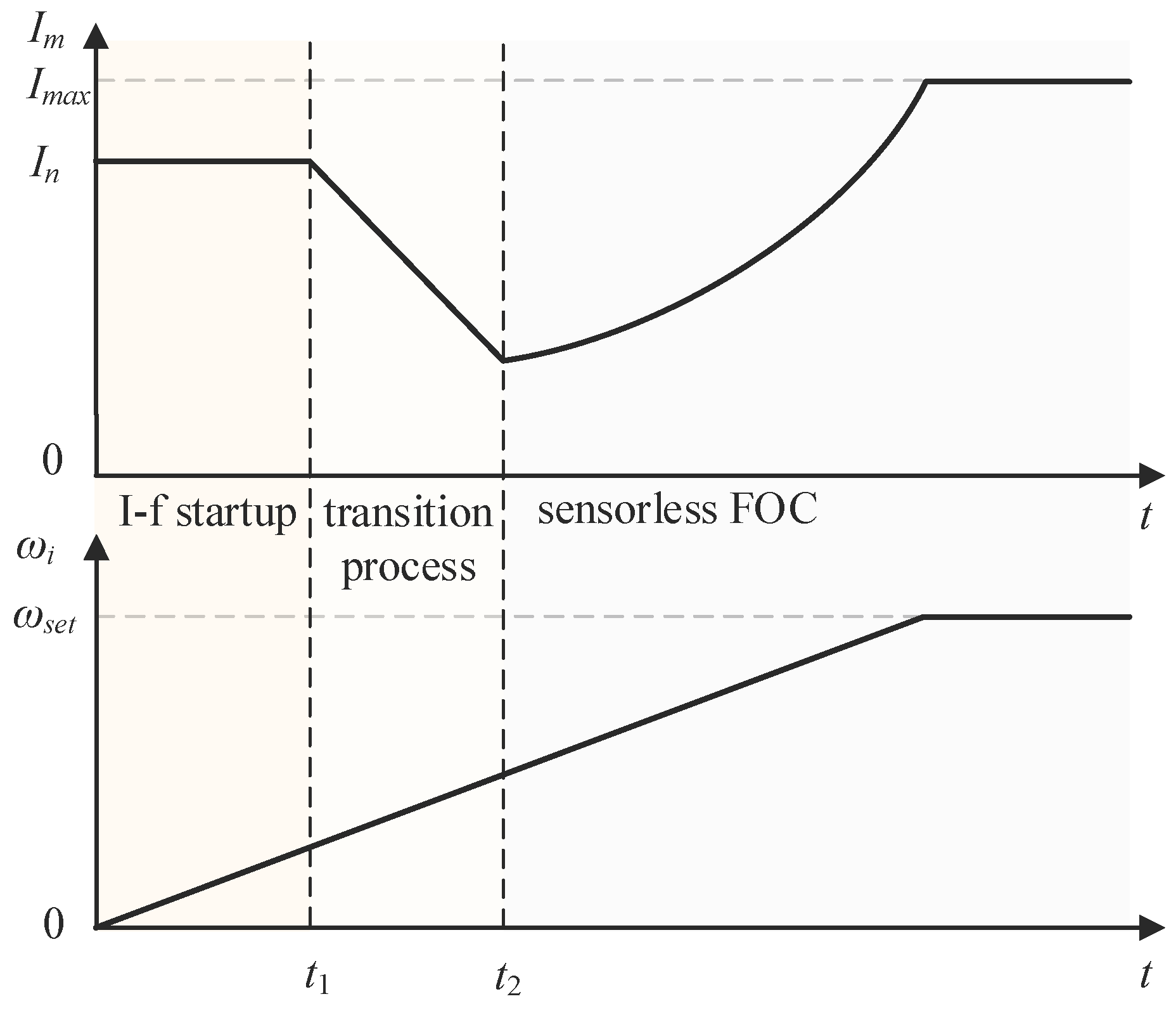
3. Conventional I-f Startup Method

I-f control establishes the relationship between reference current and reference frequency under the current closed-loop control so that the output torque is load-capable. Conventionally, the current vector amplitude is set at a large constant value, while the current vector frequency ramps up with time at a fixed ramp slope, as shown in Figure 2. The integration of the frequency yields the rotor position information needed by park and anti-park transformation, i.e.,
θ i = ω i d t .
Since the electrical response is much faster than the mechanical effect, the actual current vector can be considered to be the same as the reference current vector, where the δ-axis reference current is equal to the reference current vector amplitude (e.g., the rated value In), while the γ-axis reference current is set to 0, i.e.,
i γ = 0 , i δ = I n .
When the UHS-SPMSM exceeds the transition speed during the ramp up stage, according to the self-stabilization mechanism [31], the θerr decreases with the reduction of the reference current amplitude. Therefore, the transition from I-f control to sensorless FOC can be successfully accomplished when the θerr is smaller than a certain threshold value (e.g., 0.05 rad). It is worth noting that the estimated rotor position θ ^ e by extended EMF (EEMF)-based method proposed in [35] can be used to replace the actual one during the transition process:
θ e r r = θ e θ i θ ^ e θ i .
Generally, after successful transition, the UHS-SPMSM operates in double closed-loop control of speed and current. However, the inherent properties of speed oscillation and prone asynchronous operation of conventional I-f control cause incidental startup failures.

3.1. Inherent Speed Oscillation

Small signal model is aptly utilized to analyze the performance of UHS-SPMSM under I-f control. Therefore, the torque Equation (4) is linearized to represent the dynamic characteristics at a certain static operating point, i.e.,
Δ T e = K I Δ I K θ Δ θ e r r
with:
K I = T e I m = 1.5 n p φ f cos θ e r r K θ = T e θ e r r = 1.5 n p φ f I m sin θ e r r .
Further based on (3) and (5), small-signal models for angular error and motion equation can be obtained:
Δ θ e r r = 1 s ( Δ ω e Δ ω i ) ,
Δ ω e = n p J s + B ( Δ T e Δ T L ) .
The small signal model is schematically shown in Figure 3 with combination of (9)–(12).
With Δωi = 0 and ΔI = 0, the closed-loop transfer function from ΔTL to Δωe is obtained as follows:
G ( s ) = Δ ω e Δ T L = n p s J s 2 + B s + n p K θ .
The characteristic equation of the system under I-f control is obtained as:
J s 2 + B s + n p K θ = s 2 + 2 ζ ω n s + ω n 2 = 0
with:
ζ = B 2 J n p K θ ,   ω n = n p K θ J
where ζ and ωn denote the damping ratio and natural frequency.
ζ is very small with consideration to the relatively small B of UHS-SPMSM, which causes slow system response and large speed oscillation. At a certain static operating point, the load torque variation can be approximated considered as a step change, so the unit step response of the UHS-SPMSM according to (13) is derived as:
c ( t ) = L 1 ( G ( s ) 1 s ) = L 1 ( n p s J s 2 + B s + n p K θ 1 s ) = J ω n e ζ ω n t K θ 1 ζ 2 sin ω d t = A sin ω d t
with ω d = ω n 1 ζ 2 .
It is evident that Δωe and ΔTL exhibit opposite changing trends, and the increase of ΔTL leads to the inherent speed oscillation with oscillation frequency ωd and oscillation amplitude A. Excessive speed oscillation during initial startup interval and transition process tends to cause startup failure and transition failure, respectively.

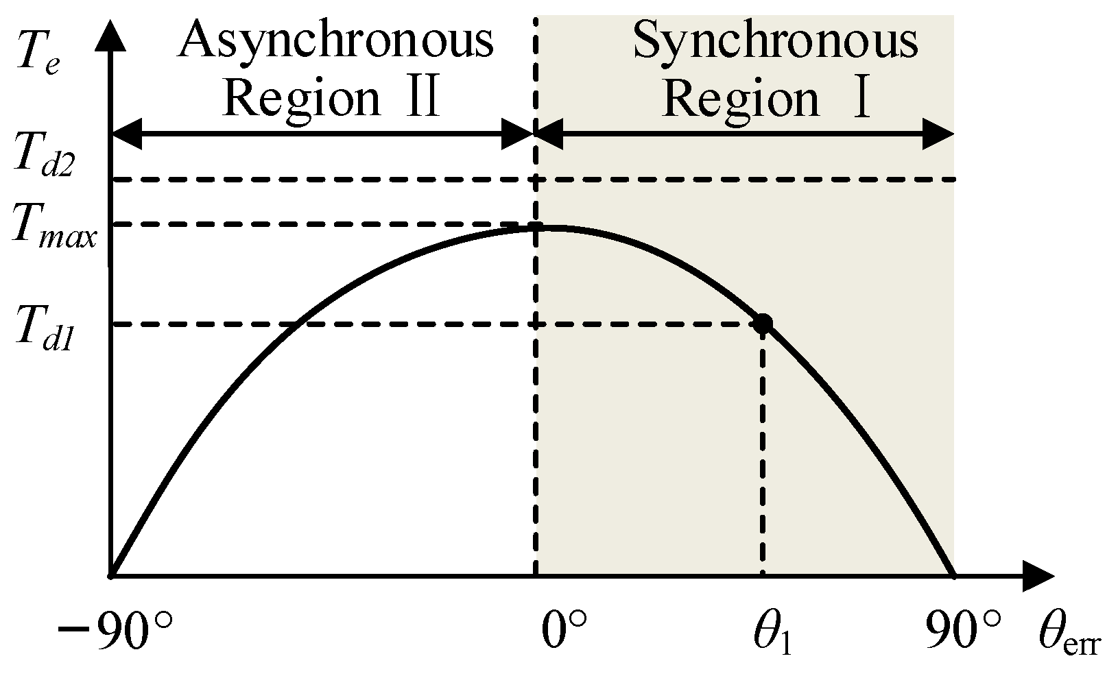
3.2. Prone Asynchronous Operation

The UHS-SPMSM is typically characterized by a steep ramp slope (e.g., 1000 π rad/s2) to facilitate rapid startup, and by considerable load torque considering the approximate quadratic correlation between motor load torque and speed. According (5), the demand torque Td comprises the load torque TL, the acceleration torque Ta, and the friction torque Tf.
T d = J d ω m d t + T L + B ω m = T a + T L + T f
Once Td exceeds the maximum electromagnetic torque Tmax under high-ramp-slope and heavy-load conditions, the I-f control may be prone to failure, leading to losing synchronization issues. Referring to (4), the variation between Te and θerr can be roughly illustrated in Figure 4. Depending on whether θerr exceeds 0, the operating region can be categorized into synchronous region I and asynchronous region II.
According to (4), when the electromagnetic torque Te is balanced with the Td, θerr maintains constant, and the rotor synchronously follows the current vector. Upon a sudden increase in TL, the rotor undergoes deceleration, leading to a reduction in θerr. This prompts Te and TL to establish a new balance. Maintaining a constant current vector amplitude, as TL gradually rises, θerr continues to decrease, reaching a minimum value at θerr = 0, signifying synchronization with the δ-axis for the reference current vector. The above characteristics manifest in synchronous region I. Conversely, in asynchronous region II, θerr and Te have the same trend. Once Te loses its capacity to match Td, the motor loses synchronization. In summary, the permissible range of θerr is defined as:
0 ° < θ e r r < 90 ° .

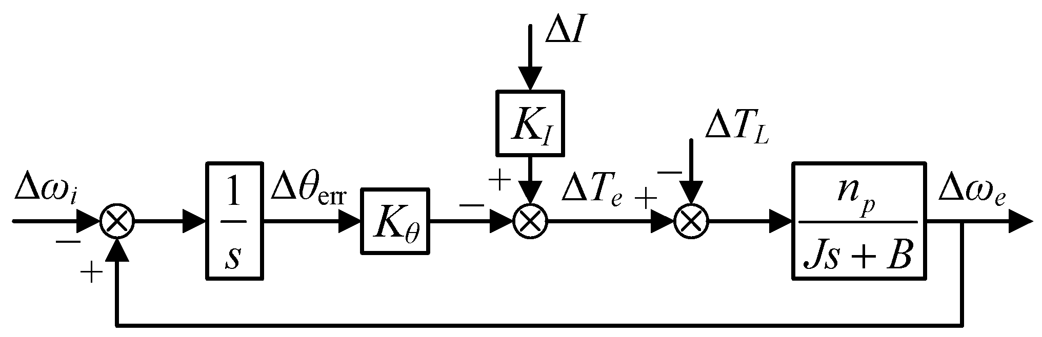
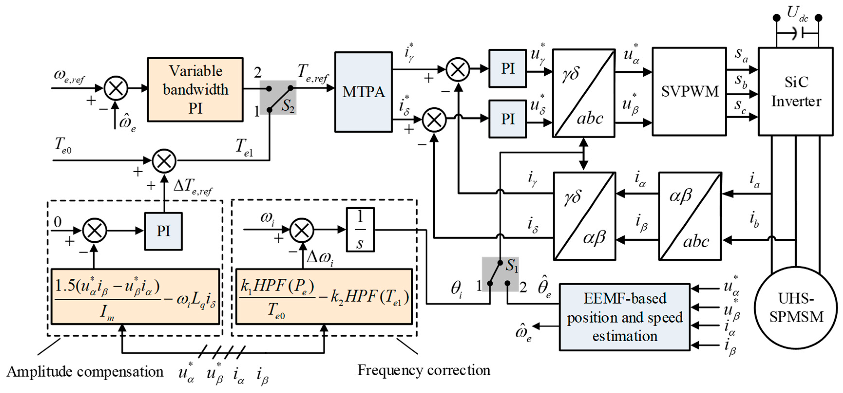
4. Proposed Closed-Loop I–f Startup Method with Transition Enhancement

4.1. Frequency Correction Design

According to active power equation, the motor frequency satisfies ωe = Pe/Te, where Pe represents the active power. Thus, the derivative of motor frequency is obtained as:
d d t ω e = d d t ( P e T e ) H P F ( P e ) T e
with P e = 1.5 ( u α * i α + u β * i β ) , where u α * ,   u β * ,   i α ,   i β are the voltage commands and currents in the α-β reference coordinate frame.
The prerequisite for the establishment of (19) is that Te keeps constant under θerr = 0 during ramp up stage. The high pass filter (HPF) is utilized as a differentiator approximately under low frequency. Therefore, the following correction frequency ∆ωi1 is designed proportional to the derivative of motor frequency in [24]:
Δ ω i 1 = k 1 d d t ω e = k 1 H P F ( P e ) T e 0
where k1 > 0 denotes the active power based correction gain, and Te0 denotes the initial reference motor torque at startup, which is set as the constant rated value.
However, the reference motor torque changes significantly in the whole startup process due to amplitude compensation (see Section 4.2 for details) and sensorless transition. Therefore, the above frequency correction method is underperforming. The additional correction frequency ∆ωi2 proportional to the electromagnetic torque variation is designed in this paper to enhance the startup performance:
Δ ω i 2 = k 2 d d t T e 2 = k 2 H P F ( T e 1 )
where k2 > 0 denotes the electromagnetic torque based correction gain, and Te1 is the real-time reference motor torque.
Therefore, the whole correction frequency can be expressed as:
ω i ω i 0 = Δ ω i 1 + Δ ω i 2 .
where ωi0 is current vector frequency without frequency correction. The whole correction frequency is activated at zero motor speed. The corresponding small-signal equation of (22) can be obtained:
Δ ω i = Δ ω i 0 k 1 d d t Δ ω e + k 2 d d t Δ T e .
Substituting (23) into (11), the angle error θerr with frequency correction can be obtained as:
θ e r r = 1 s [ ( 1 + k 1 s ) Δ ω e Δ ω i 0 k 2 s Δ T e ] .
With combination of (9), (10), (12), and (24), the closed-loop transfer function from ΔTL to Δωe is renewed with frequency correction as follows:
G ( s ) = Δ ω e Δ T L = ( k 2 K θ 1 ) n p s ( 1 k 2 K θ ) J s 2 + B e s + n p K θ
with B e = ( 1 k 2 K θ ) B + n p k 1 K θ n p k 1 K θ ( B n p k 1 K θ ) .
Therefore, the new system damping ratio ζe can be obtained as follows:
ζ e = n p k 1 K θ 2 ( 1 k 2 K θ ) J n p K θ .
Compared with system damping ratio ζe0 with only correction frequency Δωi1 as follows [24]:
ζ e 0 = n p k 1 K θ 2 J n p K θ ,
ζe is larger with the increase of k2 in a certain range. Thus, faster convergence with less oscillation can be guaranteed with the increase of system damping ratio.

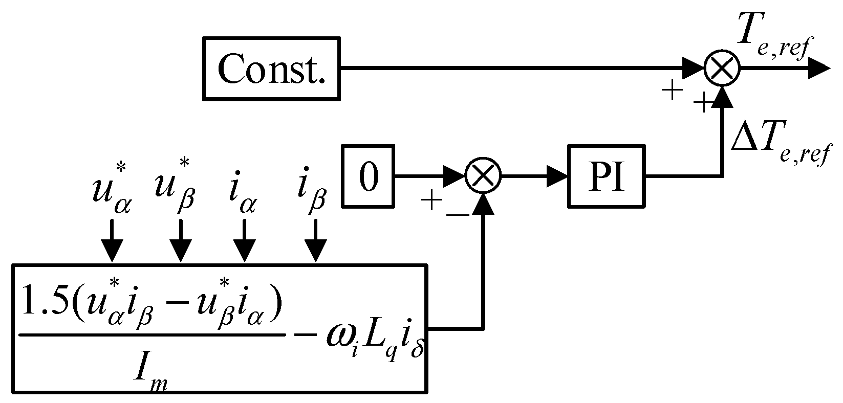
4.2. Amplitude Compensation Design

Conventional I-f control necessitates setting the reference current amplitude Im (proportional to reference motor torque) to a relatively large value to ensure that θerr remains well within the stability domain boundaries. This is performed to provide the motor with an ample stabilization margin when encountering disturbances. However, such an approach significantly increases motor losses.
According to (4), Te generated under the same Im increases with the rise of cosθerr. By maintaining cosθerr at its maximum value throughout the motor startup process, i.e., cosθerr = 1 with θerr = 0, the UHS-SPMSM under I-f control can be effectively operated in the MTPA state. This approach reduces Im, enhancing the motor’s overall operating efficiency.
The information containing θerr can be obtained from (2):
ω e φ f sin θ e r r = u γ ω i L q i δ
where uγ can be derived from reactive power as follows [36]:
u γ = U sin φ = 1.5 ( u β * i α u α * i β ) I m .
It is worth stating that the used reactive power is calculated from voltages and currents in the α-β reference coordinate frame instead of γ-δ ones, which reduces the influence of inaccurate position information on the calculation result. Hence, a PI controller can be devised to regulate Im with compensation of ΔIm. For the ease of transition to sensorless FOC, in this paper, the regulation of reference motor torque is utilized with compensation of ΔTe,ref, as illustrated in Figure 5, where ωeφfsinθerr serves as the feedback value with a reference set at 0.
Notably, u α * and u β * can be obtained from the α-β axes voltage commands for SVPWM. iα and iβ can be obtained from the sampled three-phase currents through Clarke coordinate transformation, and thus Im is also obtained. Additionally, iδ can be obtained through Park coordinate transformation based on corrected rotor position information (integral of corrected frequency). Lq is known from the motor manufacturer. In view of the above known signals, ωeφfsinθerr can be calculated directly avoiding additional observation. Therefore, the amplitude-compensated PI controller is activated at zero speed. Utilizing the amplitude-compensated PI controller, ωeφfsinθerr can converge to 0, signifying the convergence of θerr to 0. Referencing (10), it becomes apparent that Kθ = 0 when θerr = 0. By substituting Kθ = 0 to (25), the proposed I-f control with frequency correction can be likened to a first-order delay system. Therefore, adjustments in the control variables (current and frequency) influence the motor’s electromagnetic torque and speed response over time, leading to a dampened response and diminishing speed oscillations effectively.

4.3. Sensorless Transition Enhancement

After transition from I-f startup strategy to EEMF-based sensorless FOC, the estimated rotor position and speed will be utilized to coordinate transformation and as feedback value of speed PI controller, respectively. Taking the first-order low-pass filtering effect for high-frequency noise suppression in digital sampling system into consideration, the closed-loop transfer function of the speed loop can be expressed as follows [37,38]:
G s c ( s ) = ω m ( s ) ω m * ( s ) = K T K i J s 2 + ( K T K p + B ) s + K T K i = ω n s 2 s 2 + 2 ζ s ω n s s + ω n s 2
with:
ζ s = K T K p + B 2 J K T K i ,   ω n s = K T K i J
where Kp and Ki are the proportional and integral gains of speed PI controller; KT = 1.5npφf denotes the torque constant; ζs and ωns denote the damping ratio and natural frequency of the speed loop control system.
The amplitude-frequency characteristic of (30) at the closed-loop bandwidth is:
M ( ω b ) = ω n s 2 ( ω n s 2 ω b 2 ) 2 + ( 2 ζ s ω n s ω b ) = 2 2 .
Therefore, speed loop bandwidth ωb is derived with ζs and ωns:
ω b = ω n s 1 2 ζ s 2 + 2 4 ζ s 2 + 4 ζ s 4 .
Without variation of motor parameters, ωb is only dependent on the control gains of speed PI controller. Generally, UHS-SPMSM operates over a wide frequency range with fast response requirement, a large ωb is often designed more reasonably with matched constant Kp and Ki. When the UHS-SPMSM operates at low speed, particularly during the sensorless transition stage, lager speed overshoot and increased sensitivity to high-frequency noise result from an excessive ωb, heightening the risk of transition failure. Therefore, in this paper, a variable bandwidth speed PI controller is designed based on variable PI control gains, which are designed as:
K p = 2.1176 × 10 9 ω m + 2.4776 × 10 4 K i = 2.2353 × 10 8 ω m + 0.0016 .
Considering the variation trend of Kp and Ki with ωm ramping up, it is evident that ζs decreases and ωns varies oppositely. From (33), with ωns remaining constant, ωb monotonically increases with the decrease in ζs. In summary, the design of (34) prompts the increasing trend of ωb during motor speedup in the whole speed range. This mitigates the risk of transition failure from large speed oscillation after enabling speed PI controller. Hereto, the overall schematic diagram of the proposed I-f startup method with transition to FOC is illustrated as Figure 6.

5. Experimental Results

In order to validate the proposed startup method, the experiments are conducted on the test platform as shown in Figure 7, mainly including a test UHS-SPMSM, a homemade inverter, and some other ancillary equipment for control of cooling system, measuring system, and power supply system. The parameters of this UHS-SPMSM drive system are given in Table 1. For the homemade inverter, Wolfspeed CAB011M12FM3 Half-Bridge SiC power modules are designed as power switches and microprocessor TMS320F28335 DSP (provided by Texas Instruments) is designed as the control board. The switching frequency is 40 kHz and the sampling frequency is 20 kHz.
The main control parameters used are: the PI controllers for regulating γδ-axes currents are Kp,cur = 0.7 and Ki,cur = 0.002, and for regulating motor speed (without variable bandwidth design) are Kp,spd = 0.0000095 and Ki,spd = 0.0095; for frequency correction design, the correction gains are designed as k1 = 3 and k2 = 35; for amplitude compensation design, the PI control parameters are Kp,amp = 0.000006 and Ki,amp = 0.005. All the results presented in this section are analyzed via CAN communication. That is, γδ-axes currents and motor speed are logged, parsed, and plotted via Busmaster, CANoe, and Origin, respectively. After transition to FOC, EEMF-based sensorless control method proposed in our previous research [35] works. While the estimated position may be distorted at low speeds, the estimated speed remains precise, effectively representing the actual motor speed without reliance on mechanical speed measurement.
In fact, without a position sensor installation for the UHS-SPMSM, the actual dq-axes currents cannot be obtained in the experiments due to lack of real rotor position information. Therefore, the γδ-axes currents are used in this section for effectiveness validation of the proposed method. On one hand, before the sensorless transition, the γδ-axes currents are derived from the position θi in the γ-δ reference coordinate frame. On the other hand, after the sensorless transition, the γδ-axes currents are derived from the position θ ^ e in the d-q reference coordinate frame (assuming that θerr ≈ 0, γ-δ reference coordinate frame is aligned with d-q one).

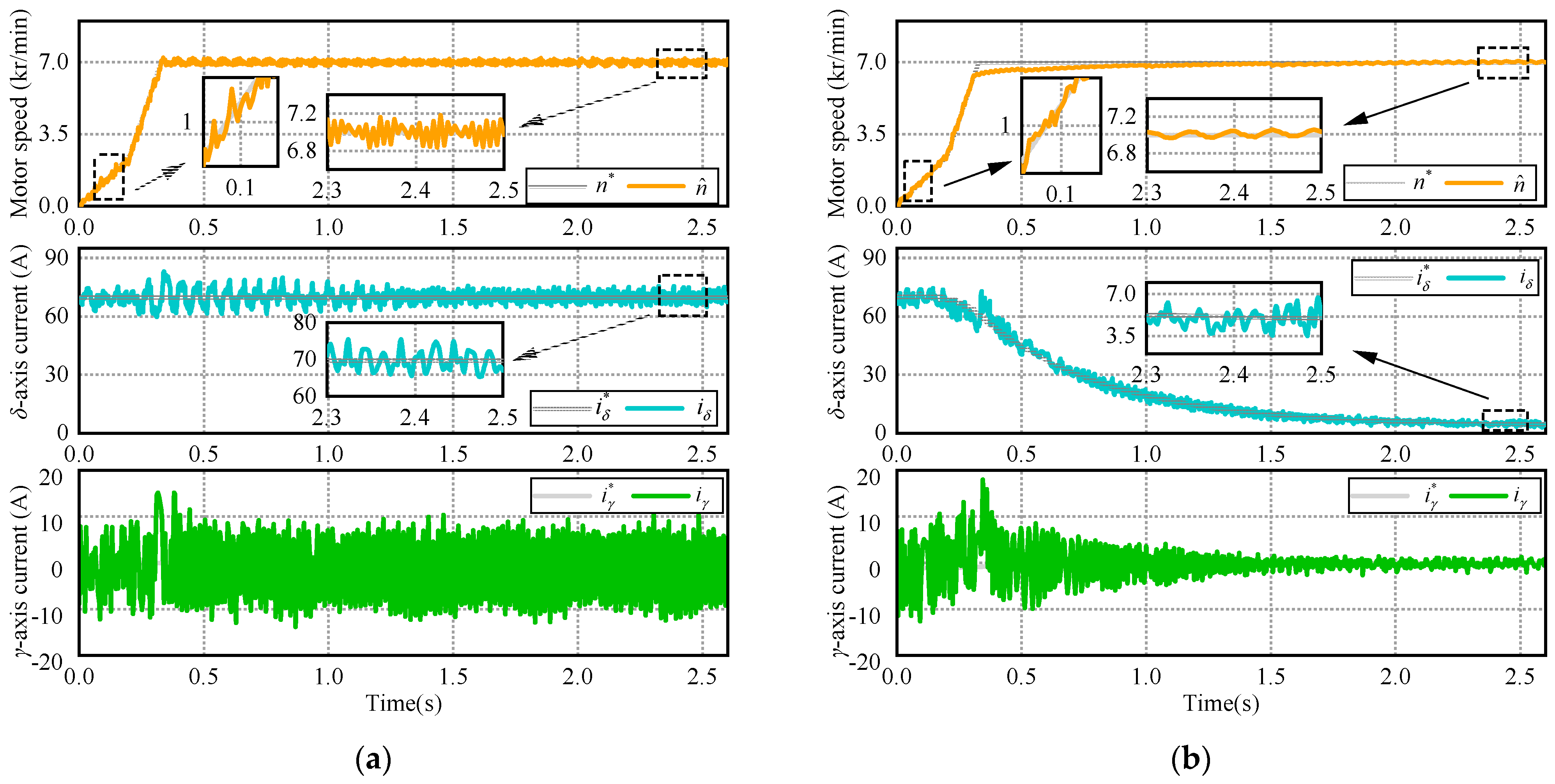
5.1. Startup Performance Comparison with Conventional I–f Startup Strategy

To verify the superior startup performance of the proposed method compared with the conventional open-loop I-f control, the UHS-SPMSM is started to 7000 r/min from a standstill.
Figure 8 shows the startup performance of the conventional I-f control. The δ-axis reference current i δ * for the I-f control is generally chosen to be a large value for a reliable startup with large output torque, and i δ * = 70 A (80% rated current) is used here. In Figure 8a, the actual δ-axis current iδ converges to the initial set value of reference current under the whole startup process, and oscillates with a maximum amplitude of 9.8 A in steady state. In addition, even the actual γ-axis current converges to 0 A under current loop PI control, the fluctuations are noticeable with an average amplitude over 10 A. This implies that an obvious position error exists between the γ-δ and d-q reference coordinate frame without amplitude compensation of reference current vector, which is not desired. Furthermore, under conventional I-f control, motor speed fluctuations occur both in dynamic process and steady-state operation, and the root mean square errors (RMSEs) are 296 r/min and 348 r/min, respectively.
Figure 8b shows the startup performance of the proposed I-f control. The initial δ-axis reference current i δ * is set the same as the conventional I-f control; however, i δ * decreases gradually with motor speedup. Only 5.1 A δ-axis current can maintain motor’s steady-state operation; compared with a conventional I-f control, it decreased 92.7%. This is due to the designed amplitude compensation of reference current. Although the effect of amplitude compensation is not so obvious at zero speed, the preliminary calculation of reactive power after motor startup is also helpful for the subsequent adjustment of amplitude compensator with motor speedup. Notably, the steady-state current oscillation of iδ is significantly decreased with maximum amplitude of only 3.2 A, which decreased 67.3% compared with the conventional I-f control. Under proposed I-f control, stable iγ = 0 operation is achieved easily, which leads to higher motor efficiency avoiding too large current amplitude fluctuations. Except slightly poorer dynamic speed tracking performance, the proposed method also has smaller dynamic and steady-state speed fluctuation of just 130 r/min and 78 r/min, respectively.
It is worth noting that to ensure fast startup, in practical engineering applications, the I-f control is only used to drive the UHS-SPMSM from standstill to a certain speed, and then transitions to the closed-loop FOC during the acceleration process. In other words, the I-f control does not enable under steady-state operating conditions. The transition process will be demonstrated in the Section 5.2. Therefore, the proposed I-f control is unaffected from the slightly poor dynamic convergence performance in practical applications.

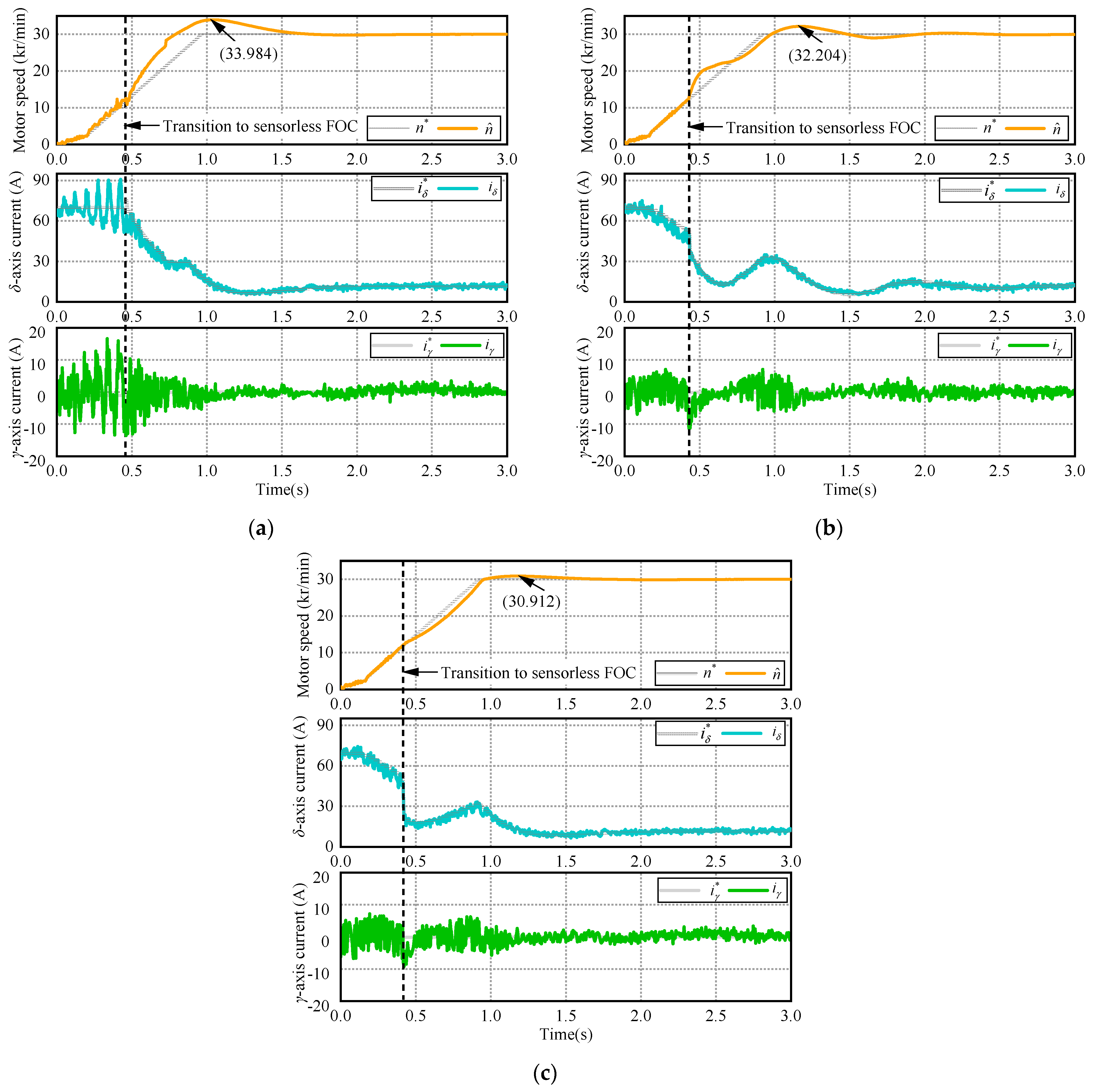
5.2. Transition Performance Comparison from I–f Startup to Sensorless FOC

To ensure the fast startup ability of the UHS-SPMSM, the transition from I-f control to sensorless FOC is usually accomplished during the acceleration process, rather than in the steady-state condition. The transition speed should be set as low as possible under the premise of position estimation accuracy of the sensorless control. Generally, the UHS-SPMSM is only operated above the idle speed (30,000 r/min for the test motor) in the actual working condition for extending the life of air bearing. Therefore, Figure 9 shows the transition performance comparison, where the UHS-SPMSM is started from a standstill to the idle speed, and the transition speed is set to 12,000 r/min.
Figure 9a shows the transition performance of conventional I-f control, where the speed PI controller is set fixed-gain. During the conventional I-f control stage, the actual δ-axis current converges poorly to the constant reference δ-axis current. The γδ-axes current tracking error increases with the gradual rise of motor speed, which indicates that the used rotor position gained from I-f control exists, growing the position error as the motor speed increases. This leads to considerable current amplitude and the increasing possibility of motor shutdown due to the overcurrent protection trigger. In addition, significant speed oscillation is evident. This is due to the poor damping as analyzed in Section 3. At the transition instant of t = 0.46 s, the reference δ-axis current has an obvious pulse due to position mismatch between the I-f control and sensorless control, which may lead to transition failure. After successful transition to the sensorless FOC, the actual motor speed has a large overshoot in the process of tracking the reference speed. The dynamic overshoot gradually increases, and the steady-state overshoot value reaches 3984 r/min.
Figure 9b shows the transition performance of the proposed closed-loop I-f control, where the speed PI controller is also set fixed-gain. During the proposed I-f control stage, the δ-axis current gradually decreases with motor speedup. This is attributed to the amplitude compensation design. In other words, the UHS-SPMSM can achieve the same motor speed under the proposed I-f control at a smaller current, which is conductive to improve the motor efficiency. Meanwhile the γδ-axes current fluctuation and speed oscillation are significantly reduced compared to the conventional I-f control, which confirms the damping effect of the frequency correction. The UHS-SPMSM can instantly switch to the sensorless FOC without any reference δ-axis current pulses, which indicates more precision in used rotor position and contributes to smoother transition.
During initial sensorless FOC stage, the δ-axis current showed a certain extent of fluctuation, which brought the simultaneous speed fluctuation. Compared with the conventional I-f control, the average δ-axis current from the transition instant to the steady state is significantly reduced, which also reflects the improvement of the motor efficiency, and its steady-state speed overshoot value is very small, only 2204 r/min. It is worth noting that the fixed-gain speed PI controller, after transition, featuring in a large bandwidth of effectiveness in the whole speed range, holds redundant bandwidth at the transition speed of 12,000 r/min. This causes the speed and current fluctuation.
Figure 9c shows the transition performance of the proposed closed-loop I-f control with variable bandwidth speed PI controller. Clearly, the δ-axis current and speed fluctuation are significantly reduced after transition, and the steady-state speed overshoot is reduced to 912 r/min. Sensorless transition enhancement obtains a smooth transition compared with fixed-bandwidth speed PI controller. Therefore, transition failure can be avoided for high startup reliability.

6. Conclusions

In this article, a reliable and efficient I-f control method with transition enhancement is introduced for UHS-SPMSMs driving fuel cell air compressors. The startup reliability and transition smoothness are visibly enhanced. The main conclusions are summarized as follows:
(1)
During the speed up stage, the proposed frequency correction of reference current vector considering the active power and motor torque simultaneously, which reduces the speed oscillation significantly, while decreasing the possibility of startup failure.
(2)
The proposed amplitude compensator of reference current vector obviously reduces the current amplitude under the same startup condition, which ensures MTPA operation. This characteristic improves the motor efficiency significantly and prerequisites smoother transition from I-f startup to sensorless FOC due to minimizing the current vector angle.
(3)
After the transition to sensorless FOC with an enabling speed PI controller, the proposed variable bandwidth scheme ensures reduction of current amplitude and speed fluctuation, avoiding transition failure.
Generally, the contributions investigated in this paper can be extendedly applied to UHS-SPMSM driving gas turbines, electric turbochargers, flywheels for energy storage, and turbo-electric distributed propulsion system for aircraft, rather than merely driving fuel cell air compressors.

Author Contributions

Conceptualization, J.X.; Data curation, Y.X.; Formal analysis, Y.L.; Funding acquisition, J.Z.; Investigation, J.X.; Methodology, Y.X.; Project administration, J.X.; Resources, J.Z.; Software, Y.X.; Supervision, J.Z.; Validation, Y.X.; Visualization, X.J.; Writing—original draft, Y.X.; Writing—review and editing, J.X. and Y.X. All authors have read and agreed to the published version of the manuscript.

Funding

This research was funded by the National Key R&D Program of China sponsored by Ministry of Science and Technology of the People’s Republic of China (MoST), grant number 2022YFB25031013.

Data Availability Statement

The data that support the findings of this study are available on request from the corresponding author. The data are not publicly available due to privacy restrictions.

Conflicts of Interest

The authors declare no conflicts of interest.

References

  1. Zhang, J.; Peng, F.; Huang, Y.; Yao, Y.; Zhu, Z. Online Inductance Identification Using PWM Current Ripple for Position Sensorless Drive of High-Speed Surface-Mounted Permanent Magnet Synchronous Machines. IEEE Trans. Ind. Electron. 2022, 69, 12426–12436. [Google Scholar] [CrossRef]
  2. Zhang, Q.; Yu, R.; Li, C.; Chen, Y.-H.; Gu, J. Servo Robust Control of Uncertain Mechanical Systems: Application in a Compressor/PMSM System. Actuators 2022, 11, 42. [Google Scholar] [CrossRef]
  3. Looser, A.; Kolar, J.W. An Active Magnetic Damper Concept for Stabilization of Gas Bearings in High-Speed Permanent-Magnet Machines. IEEE Trans. Ind. Electron. 2014, 61, 3089–3098. [Google Scholar] [CrossRef]
  4. Kim, J.H.; Kim, D.M.; Jung, Y.H.; Lim, M.S. Design of Ultra-High-Speed Motor for FCEV Air Compressor Considering Mechanical Properties of Rotor Materials. IEEE Trans. Energy Convers. 2021, 36, 2850–2860. [Google Scholar] [CrossRef]
  5. Xu, Y.; Lin, C.; Xing, J.; Li, X. Extended State Observer-Based Position Sensorless Control for Automotive Ultra-high-Speed PMSM. In Proceedings of the China SAE Congress 2022: Selected Papers; Springer: Singapore, 2023; pp. 787–799. [Google Scholar]
  6. Chi, W.-C.; Cheng, M.-Y. Implementation of a sliding-mode-based position sensorless drive for high-speed micro permanent-magnet synchronous motors. ISA Trans. 2014, 53, 444–453. [Google Scholar] [CrossRef]
  7. Zhang, Q.; Yang, D.; Kong, Q.; Sun, X.; Hu, Z. A super-high-speed PM motor drive for centrifugal air compressor used in fuel cell unmanned aerial vehicle. IET Electr. Power Appl. 2023, 17, 1459–1468. [Google Scholar] [CrossRef]
  8. Niedermayr, P.; Alberti, L.; Bolognani, S.; Abl, R. Implementation and Experimental Validation of Ultrahigh-Speed PMSM Sensorless Control by Means of Extended Kalman Filter. IEEE J. Emerging Sel. Top. Power Electron. 2022, 10, 3337–3344. [Google Scholar] [CrossRef]
  9. Hu, M.; Yu, W.; Lei, J.; Wu, Z.; Hua, W.; Hu, Y. Sensorless Control of a High-Speed PMSM with Rapid Acceleration for Air Compressors using a High-order Extended State Observer. In Proceedings of the 2021 IEEE Energy Conversion Congress and Exposition (ECCE), Virtual Conference, 10–14 October 2021; pp. 4781–4787. [Google Scholar]
  10. Du, B.; Wu, S.; Han, S.; Cui, S. Application of Linear Active Disturbance Rejection Controller for Sensorless Control of Internal Permanent-Magnet Synchronous Motor. IEEE Trans. Ind. Electron. 2016, 63, 3019–3027. [Google Scholar] [CrossRef]
  11. Griffo, A.; Drury, D.; Sawata, T.; Mellor, P.H. Sensorless starting of a wound-field synchronous starter/generator for aerospace applications. IEEE Trans. Ind. Electron. 2012, 59, 3579–3587. [Google Scholar] [CrossRef]
  12. Looser, A.; Tüysüz, A.; Zwyssig, C.; Kolar, J.W. Active Magnetic Damper for Ultrahigh-Speed Permanent-Magnet Machines with Gas Bearings. IEEE Trans. Ind. Electron. 2017, 64, 2982–2991. [Google Scholar] [CrossRef]
  13. Zhao, L.; Ham, C.H.; Han, Q.; Wu, T.X.; Zheng, L.; Sundaram, K.B.; Kapat, J.; Chow, L. Design of optimal digital controller for stable super-high-speed permanent-magnet synchronous motor. IEE Proc. Electr. Power Appl. 2006, 153, 213–218. [Google Scholar] [CrossRef]
  14. Ancuti, R.; Boldea, I.; Andreescu, G.-D. Sensorless V/f control of high-speed surface permanent magnet synchronous motor drives with two novel stabilising loops for fast dynamics and robustness. IET Electr. Power Appl. 2010, 4, 149–157. [Google Scholar] [CrossRef]
  15. Tang, Z.; Li, X.; Dusmez, S.; Akin, B. A New V/f-Based Sensorless MTPA Control for IPMSM Drives. IEEE Trans. Power Electron. 2016, 31, 4400–4415. [Google Scholar] [CrossRef]
  16. Datta, S.; Chandra, A.; Chowdhuri, S. High performance sensor-less V/f control of surface PMSM in voltage vector plane with ZVV injection and SMO-based position estimation method. Electr. Eng. 2022, 104, 657–666. [Google Scholar] [CrossRef]
  17. Xu, Y.; Lin, C.; Xing, J.; Zeng, Q.; Sun, J. I-f Starting Rapid and Smooth Transition Method of Full-Speed Sensorless Control for Low Current Harmonic Ultra-high-speed PMSM. In Proceedings of the 2022 IEEE Applied Power Electronics Conference and Exposition (APEC), Houston, TX, USA, 20–24 March 2022; pp. 1820–1826. [Google Scholar]
  18. Xing, J.; Qin, Z.; Lin, C.; Jiang, X. Research on Startup Process for Sensorless Control of PMSMs Based on I-F Method Combined with an Adaptive Compensator. IEEE Access 2020, 8, 70812–70821. [Google Scholar] [CrossRef]
  19. Haichao, F.; Boyang, S.; Lizhen, G. A closed-loop I/f vector control for permanent magnet synchronous motor. In Proceedings of the 2017 9th International Conference on Modelling, Identification and Control (ICMIC), Kunming, China, 10–12 July 2017; pp. 965–969. [Google Scholar]
  20. Xu, G.; Zhao, F.; Liu, T. I–f closed-loop starting strategy of high-speed PMSM based on current vector adaptive regulation. IET Power Electron. 2023, 16, 2724–2738. [Google Scholar] [CrossRef]
  21. Liu, J.; Nondahl, T.A.; Schmidt, P.B.; Royak, S.; Rowan, T.M. Generalized Stability Control for Open-Loop Operation of Motor Drives. IEEE Trans. Ind. Appl. 2017, 53, 2517–2525. [Google Scholar] [CrossRef]
  22. Liu, J.; Nondahl, T.A.; Dai, J.; Royak, S.; Schmidt, P.B. A Seamless Transition Scheme of Position Sensorless Control in Industrial Permanent Magnet Motor Drives with Output Filter and Transformer for Oil Pump Applications. IEEE Trans. Ind. Appl. 2020, 56, 2180–2189. [Google Scholar] [CrossRef]
  23. Yu, Y.; Chang, D.; Zheng, X.; Mi, Z.; Li, X.; Sun, C. A Stator Current Oriented Closed-Loop I--f Control of Sensorless SPMSM with Fully Unknown Parameters for Reverse Rotation Prevention. IEEE Trans. Power Electron. 2018, 33, 8607–8622. [Google Scholar] [CrossRef]
  24. Song, Z.; Yao, W.; Lee, K.; Li, W. An Efficient and Robust I-f Control of Sensorless IPMSM with Large Startup Torque Based on Current Vector Angle Controller. IEEE Trans. Power Electron. 2022, 37, 15308–15321. [Google Scholar] [CrossRef]
  25. Chen, D.; Lu, K.; Wang, D. An I-f Startup Method for Back-EMF based Sensorless FOC of PMSMs with Improved Stability During the Transition. In Proceedings of the 2020 International Symposium on Industrial Electronics and Applications (INDEL), Banja Luka, Bosnia and Herzegovina, 4–6 November 2020; pp. 1–6. [Google Scholar]
  26. Consoli, A.; Scelba, G.; Scarcella, G.; Cacciato, M. An Effective Energy-Saving Scalar Control for Industrial IPMSM Drives. IEEE Trans. Ind. Electron. 2013, 60, 3658–3669. [Google Scholar] [CrossRef]
  27. Chen, D.; Lu, K.; Wang, D.; Hinkkanen, M. I-F Control with Zero D-Axis Current Operation for Surface-Mounted Permanent Magnet Synchronous Machine Drives. IEEE Trans. Power Electron. 2023, 38, 7504–7513. [Google Scholar] [CrossRef]
  28. Nair, S.V.; Hatua, K.; Prasad, N.V.P.R.D.; Reddy, D.K. A Quick I-f Starting of PMSM Drive with Pole Slipping Prevention and Reduced Speed Oscillations. IEEE Trans. Ind. Electron. 2021, 68, 6650–6661. [Google Scholar] [CrossRef]
  29. Na, H.; Cho, K.-Y.; Kim, H.-W.; Kim, S.-H. Stable sensorless transition algorithm for PM synchronous motors under load. J. Power Electron. 2024, 24, 608–617. [Google Scholar] [CrossRef]
  30. Ning, B.; Zhao, Y.; Cheng, S. An Improved Sensorless Hybrid Control Method of Permanent Magnet Synchronous Motor Based on I/F Startup. Sensors 2023, 23, 635. [Google Scholar] [CrossRef] [PubMed]
  31. Wang, Z.; Lu, K.; Blaabjerg, F. A Simple Startup Strategy Based on Current Regulation for Back-EMF-Based Sensorless Control of PMSM. IEEE Trans. Power Electron. 2012, 27, 3817–3825. [Google Scholar] [CrossRef]
  32. Tang, Q.; Chen, D.; He, X. Integration of Improved Flux Linkage Observer and I–f Starting Method for Wide-Speed-Range Sensorless SPMSM Drives. IEEE Trans. Power Electron. 2020, 35, 8374–8383. [Google Scholar] [CrossRef]
  33. Liu, L.; Jin, D.; Si, J.; Liang, D. A novel nonsingular fast terminal sliding mode observer combining I-F method for wide-speed sensorless control of PMSM drives. IET Power Electron. 2023, 16, 843–855. [Google Scholar] [CrossRef]
  34. Fatu, M.; Teodorescu, R.; Boldea, I.; Andreescu, G.D.; Blaabjerg, F. I-F starting method with smooth transition to EMF based motion-sensorless vector control of PM synchronous motor/generator. In Proceedings of the 2008 IEEE Power Electronics Specialists Conference, Rhodes, Greece, 15–19 June 2008; pp. 1481–1487. [Google Scholar]
  35. Xu, Y.; Lin, C.; Xing, J. Transient Response Characteristics Improvement of Permanent Magnet Synchronous Motor Based on Enhanced Linear Active Disturbance Rejection Sensorless Control. IEEE Trans. Power Electron. 2023, 38, 4378–4390. [Google Scholar] [CrossRef]
  36. Chen, D.; Lu, K.; Wang, D. An I-f Startup Method with Compensation Loops for PMSM with Smooth Transition. IEEJ J. Ind. Appl. 2020, 9, 263–270. [Google Scholar] [CrossRef]
  37. Du, C.Y.; Yu, G.R. Optimal PI Control of a Permanent Magnet Synchronous Motor Using Particle Swarm Optimization. In Proceedings of the Second International Conference on Innovative Computing, Informatio and Control (ICICIC 2007), Kumamoto, Japan, 5–7 September 2007; p. 255. [Google Scholar]
  38. Choi, J.W.; Lee, S.C. Antiwindup Strategy for PI-Type Speed Controller. IEEE Trans. Ind. Electron. 2009, 56, 2039–2046. [Google Scholar] [CrossRef]
Figure 1. Vector diagram including d-q and γ-δ frames for UHS-SPMSM.
Actuators 13 00203 g001
Figure 2. Current vector amplitude and frequency of conventional I-f control.
Actuators 13 00203 g002
Figure 3. Small signal model of UHS-SPMSM under conventional I-f control.
Actuators 13 00203 g003
Figure 4. The variation between Te and θerr.
Actuators 13 00203 g004
Figure 5. Amplitude compensation design.
Actuators 13 00203 g005
Figure 6. The overall schematic diagram of the proposed I-f startup method, including transition to FOC. The two switches (S1 and S2) are connected to terminal 1 for the proposed I-f control and 2 for sensorless FOC (where MTPA denotes maximum torque per ampere and SVPWM denotes space vector pulse width modulation, and EEMF-based position and speed estimation can be found in our previous research [35]).
Actuators 13 00203 g006
Figure 7. Overall experimental system test bench.
Actuators 13 00203 g007
Figure 8. Startup performance from standstill to 7000 r/min. (a) Conventional I-f control. (b) Proposed closed-loop I-f control.
Actuators 13 00203 g008
Figure 9. Startup performance from standstill to 30,000 r/min with transition from I–f control to sensorless FOC at 12,000 r/min. (a) Conventional I-f control with fixed-gain speed PI controller. (b) Proposed closed-loop I-f control with fixed-gain speed PI controller. (c) Proposed closed-loop I-f control with variable bandwidth speed PI controller.
Actuators 13 00203 g009
Table 1. Parameters of the UHS-SPMSM drive system.
SymbolParameterValue
PNRated power35 kW
ωe,ratedRated speed9245 rad/s (90 kr/min)
ωe,maxMaximum speed9948 rad/s (95 kr/min)
ωe,minMinimum speed3142 rad/s (30 kr/min)
ωNFundamental frequency1.583 kHz
npPole pairs1
RsStator resistance0.0085 Ω
Ldd-axis inductance66.46 μH
Lqq-axis inductance66.46 μH
φfFlux linkage0.02387 Wb
JMotor inertia0.0005672 kg·m2
UDCDC bus voltage550 V
fswSwitching frequency40 kHz
fcControl frequency20 kHz
TsSampling period0.00005 s
Disclaimer/Publisher’s Note: The statements, opinions and data contained in all publications are solely those of the individual author(s) and contributor(s) and not of MDPI and/or the editor(s). MDPI and/or the editor(s) disclaim responsibility for any injury to people or property resulting from any ideas, methods, instructions or products referred to in the content.

