Article

Optimization Design of Magnetically Suspended Control and Sensitive Gyroscope Deflection Channel Controller Based on Neural Network Inverse System

1
Graduate School, Space Engineering University, Beijing 101400, China
2
Department of Aerospace Science and Technology, Space Engineering University, Beijing 101400, China
*
Authors to whom correspondence should be addressed.
Actuators 2024, 13(8), 302; https://doi.org/10.3390/act13080302
Submission received: 5 July 2024 / Revised: 1 August 2024 / Accepted: 5 August 2024 / Published: 7 August 2024

Abstract

:
To meet the strong coupling characteristics of the MSCSG deflection channel and the demand for high control accuracy, a two-degree-of-freedom deflection channel model is firstly established for the structure and working principle of the MSCSG; to meet the strong coupling between the two channels, the inverse system method is used to decouple the model; then, the operation principle of the MSCSG system is introduced, and the modeling of the power amplifier is carried out; to meet the demand for high-precision control of the MSCSG rotor system, the RBF neural network is improved using the fuzzy method to achieve high-precision estimation of the residual coupling terms and deterministic disturbances, and the adaptive sliding mode controller is designed. For the high-precision control of the MSCSG rotor system, the fuzzy method is used to improve the RBF neural network to realize the high-precision estimation of the residual coupling term and uncertain perturbation, and the adaptive sliding mode controller is designed, and the convergence of the controller is proved on the basis of the Lyapunov stability criterion. Simulation analysis shows that the method has a large improvement in decoupling performance and anti-disturbance performance compared with the traditional method, and finally, the experiment verifies the effectiveness of the present method and achieves the optimization of the deflection channel controller. The method can be extended to other magnetic levitation actuators and related fields.

1. Introduction

A magnetically suspended control and sensitive gyroscope (MSCSG) is a new type of actuator integrating torque output and angular velocity measurement and can be applied in the fields of spacecraft attitude maneuvering, attitude measurement, and flexural vibration suppression. Especially in the field of controlling spacecraft attitude maneuvering, an MSCSG can not only control the rotor speed to output the moment in the same direction as the mounting axis, but also control the active deflection of the rotor in two degrees of freedom to change the direction of the angular momentum and output the moment in the perpendicular direction to the mounting axis. That is to say, theoretically, it has the ability to output torque in three degrees of freedom, which is of great significance for spacecraft attitude control. However, the coupling of the state quantities of the two degrees of freedom of the deflection is serious, which affects the output accuracy of the moment and restricts the output of the attitude angle. The output of the attitude angle of the deflected two degrees of freedom, with the Lorentz force magnetic bearing as the torque generator, benefits from the advantage that its output torque becomes linear with the current, and in addition to actively controlling the current magnitude output torque, it can also be sensitive to the spacecraft attitude, thus realizing the integration of the control and sensitivity and reducing the volume and cost of the spacecraft attitude control system. However, when the strong coupling exists between the two degrees of freedom of the deflection, the output moment and the current will not be strictly linear, and the precision of control and sensitivity will be greatly weakened, so it can be said that the existence of strong coupling will make the MSCSG unable to carry out the work effectively. For the problem of strong coupling of generalized two degrees of freedom, traditional control methods include cross PID, sliding mode control, configuration observer method, adaptive control method, etc., and the above methods can complement each other’s strengths and be used to design controllers accordingly for different controlled objects. For example, by designing a backstepping sliding mode controller, Sifan Han combines the advantages of backstepping control and sliding mode control, and the system rapidity and tracking accuracy are improved [1]; Xin Ning proposes a control method based on disturbance observer, which improves the robustness of the system [2]; Chao Jiang proposes a controller that combines the RBF neural network with the inverse system method, which realizes the control of a three-axis rotary table [3]; Chuchong Lin utilizes a PID controller and overshooting hysteresis controller to greatly enhance the system’s immunity and rapidity [4]. However, the inherent problems of the above methods are difficult to solve: cross-PID has weak tracking ability of the signal, and there is phase lag; sliding mode control has a difficult-to-solve jitter problem; the configuration observer method can improve the rapidity of the system to a certain extent, but there is also the problem of time lag; the adaptive control is more dependent on the control parameters, which have a large impact on the control results. All these impede the improvement of the control accuracy of a two-degree-of-freedom strongly coupled system. Therefore, this paper proposes the idea of decoupling, then compensation, then control, i.e., decoupling the MSCSG two-degree-of-freedom strong coupling using the decoupling method, then designing the compensation method to compensate for the real-time observation of the system parameters, disturbance, and other information, and finally designing the controller for high-precision control. In order to solve the problem of serious coupling of the two deflection degrees of freedom, Changfeng Xia utilizes feedforward compensation to realize the deflection decoupling of the radial two degrees of freedom [5]; Yuan Ren utilizes a perturbation observer, and after the decoupling of the radial two degrees of freedom, he corrects the filter parameters in real time to improve the output accuracy of the robust sliding-mode controller [6]; Zengxiang Yin utilizes the auto-anti-perturbation method (ADRC) to view the coupling term as an internal perturbation and observes both the internal and external perturbations in real time and compensation [7]; Li Lei utilized the learning property of radial basis (RBF) neural network and combined the RBF network with ADRC, so that ADRC has the ability of real-time parameter tuning, and designed an adaptive robust sliding-mode controller, so that the RBF network is given the self-adaptive parameters in real time to reduce the jitter of the sliding-mode controller [8]. The core of the two degrees of freedom of the MSCSG deflections is the magnetic bearings of the Lorentz force, and apart from the above methods, Xinyi Su designed a new method for the system information. Xinyi Su proposed a fuzzy adaptive terminal sliding mode control method based on a novel fully regulated recurrent neural network compensator for magnetic levitation systems with limited system information, which significantly suppresses the jitter with strong robustness [9]; Zhang Jiaji designed a nonlinear intelligent decoupling controller to stabilize the levitation system for decoupled force distribution and compensating system perturbations with an extended state observer. The controller has good transient response performance and strong robustness to parameter uncertainties and external disturbances [10]. Wei-Lung Mao proposed a reference model adaptive fuzzy Hermite controller for position tracking of a model-free magnetic bearing system and verified the robustness of the system in the presence of model uncertainties and external disturbances; the proposed scheme has better performance for the system’s transient response and steady state with good tracking performance [11].
In addition to the above methods, it has been confirmed in several published articles that combining neural networks with traditional control methods can improve the performance of control systems. Changjian Jiang proposed a decoupling control method based on an inverse system of fuzzy neural networks. Based on the reversibility analysis of the mathematical model, a fuzzy neural network is used to construct an inverse system. By connecting the inverse system in series with the original system, the original nonlinear system is decoupled into three single-input single-output linear subsystems. Simulation and experimental results show that the control method can realize the decoupling between the generation voltage and the levitation force so that the ORC-BPMSG has good dynamic performance and stability [12]. Qiu, Zhi cheng investigated a sliding-mode neural network fuzzy control (SMNNFC) method to inhibit a translationally coupled biflexible beam system consisting of an AC servomotor and multiple piezoelectric actuators to suppress the vibration, and the experimental results show that the SMNNFC scheme has certain advantages in suppressing the large and small amplitude vibration of the coupled biflexible beam system [13]. Zheng Li. established a dynamic model of a permanent magnet spherical motor (PMSM) and proposed a dynamic decoupling control algorithm based on a fuzzy controller (FCS) and a neural network recognizer (NNI). For a class of parametric uncertainty of multi-input multi-output nonlinear systems, an adaptive decoupling control method based on fuzzy neural network observer is proposed [14].
In order to improve the dynamic quality and steady-state performance of the magnetic levitation ball system, a hybrid controller based on a recurrent neural network was designed to realize the position control of a magnetic levitation ball system. The results show that the RNN-based hybrid controller has higher accuracy and faster tuning speed than the comparative controller, as well as strong anti-interference and robustness [15,16]. Armita Fatemimoghadam proposed a new method for the position adjustment of a maglev system based on the adaptive backpropagation control of a projected recurrent neural network (PRNN-ABC) [17]. Zhang Yanhong et al. designed a neural network PID quadratic optimal controller by applying optimal control theory for the characteristics of uncertainty, nonlinearity, and open-loop instability of an active maglev control system. Simulation results show that the neural network PID quadratic optimal controller can effectively improve the static and dynamic performance of the system so as to maintain the stable levitation of the rotor, thus making the active magnetic levitation system highly resistant to interference and robust [18]. In addition to the above cases, various neural-network-based control methods have also been mentioned in the literature, all of which utilize neural networks to rectify the system parameters, improve the dynamic qualities, and increase the system’s steady-state accuracy and anti-jamming effect [19,20,21,22].
However, the above methods, when decoupling the coupling terms and controller design, have high real-time requirements for the system, causing a large load on the computational capability of the controller and in turn reducing the robustness and anti-interference capability of the system. Considering that the MSCSG rotor is prone to unbalanced vibration when the rotational speed changes, the system complexity should be reduced, and the system robustness should be improved. Therefore, in this paper, on the basis of modeling and analyzing the two degrees of freedom of the MSCSG deflection, the decoupling of the two degrees of freedom of the deflection is firstly accomplished according to the inverse system method; considering that the RBF neural network needs a huge amount of arithmetic and sample size in the process of correcting the system parameters and approximating the dynamic error, fuzzy control is then introduced to correct the RBF neural network once again. The fuzzy control method of the RBF neural network, which combines the arbitrary accuracy nonlinear approximation ability of the RBF neural network and the abstraction ability of fuzzy control for complex linear systems, can significantly improve the dynamic quality of the sliding mode controller. The learning ability of the RBF neural network is introduced to modify the affiliation function and fuzzy rules of fuzzy control, which solves the subjectivity caused by fuzzy control relying too much on an empirical basis. Finally, the decoupling performance and anti-jamming performance of the control method are firstly verified by simulation, and then the advancement of the method compared with the traditional method is verified by offline experiments in the real system.

2. MSCSG System Principles and Modeling

2.1. MSCSG Structure and Principle

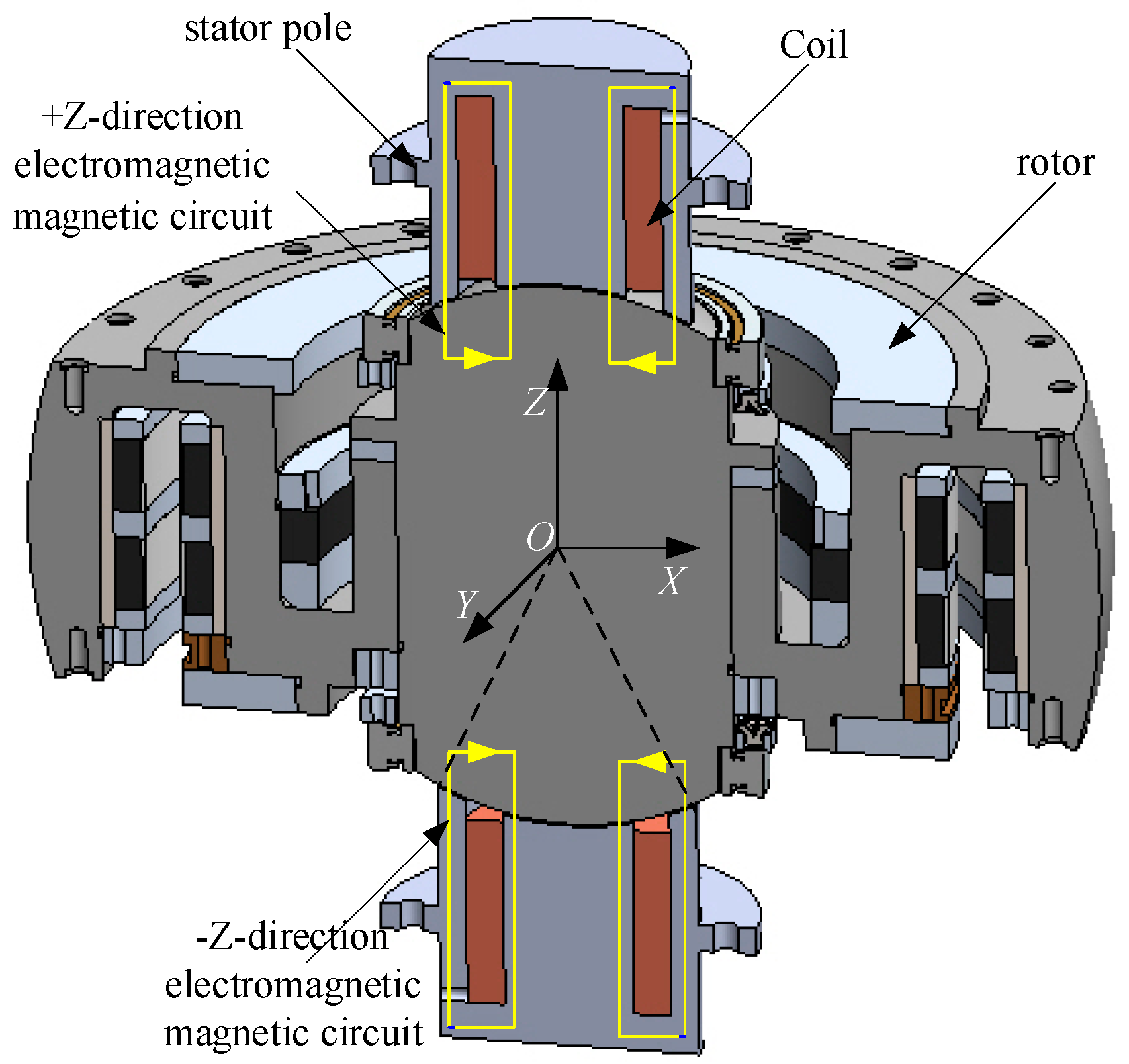
An MSCSG consists of a double-spherical rotor, radial magnetic bearings, axial magnetic bearings, Lorentz force magnetic bearings, upper, middle, and lower gyro houses, displacement sensors, drive motors, and other components. The double-spherical rotor is mounted as a round cake, with half-spherical bumps in the axial direction, and the distance from the axial spherical bumps to the radial center of the sphere is designed to be the same as the radial radius, so that the rotor receives axial and radial forces over the center of the sphere, which does not result in the coupling of axial flatness and radial deflection. Both the radial and axial magnetic bearings use magnetic-resistance-type magnetic bearings to generate translational force on the rotor and realize magnetic levitation of the rotor with three degrees of freedom. The principle of a Lorentz force magnetic bearing is that the energized coil is subjected to amperometric force in the magnetic field, and since the amperometric force is linear with the current magnitude, the Lorentz force magnetic bearing controls the rotor two-degree-of-freedom yawing without negative current stiffness and with high control accuracy. The drive motor realizes the high-speed rotation of the rotor, and it controls the rotor speed by controlling the duty cycle of the PWM signal in the motor, the size of the current, and other parameters. The upper, middle, and lower gyro houses are the subject of the stator section, and the magnetic bearings, motor, and assembly connectors are fixed to the gyro houses. The structure of the MSCSG is shown in Figure 1.
The Lorentz force magnetic bearing control torque along X , Y direction is
P x = 2 B L D i α P y = 2 B L D i β
i α , i β is the excitation current that controls the rotation of the rotor along the X , Y -axis. The gyro-technical equation for the MSCSG rotor rotating at high speed is
P x = J x α ¨ + J z Ω β ˙ P y = J y β ¨ J z Ω α ˙
α , β is the radial deflection of the rotor about the X , Y -axis, and Ω is the angular velocity of the rotor in the axial direction. J x , J y is the moment of inertia of the rotor with respect to the X , Y -axis, which is the same as the equatorial moment of inertia of the rotor, J r .

2.2. Sensor Principle

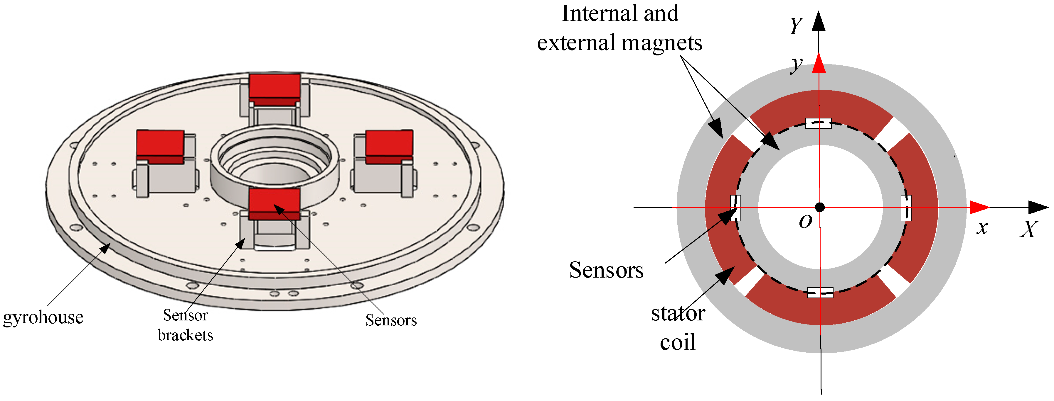
The MSCSG rotor has a total of six degrees of freedom of motion, i.e., axial rotation, axial translation, radial two-degree-of-freedom deflection, and radial two-degree-of-freedom translation. Except for the axial rotation degree of freedom, the remaining five degrees of freedom are controlled and driven by magnetic levitation bearings, and all of them are used to obtain the rotor’s bit information through eddy current sensors. The four position sensors of the MSCSG deflection channel are mounted on the sensor bracket of the upper gyro room, configured in the way shown in Figure 2. The four sensors are in the same plane over the origin of the stator coordinate system, o, to the projection of the detection surface, as shown by the black dashed line in Figure 2.
The geometric coordinate system o-xyz is defined with the origin of the stator coordinate system o as the origin, where the x-axis and y-axis coincide with the centerlines of the two sets of coils in the relative directions, respectively, and the direction of the z-axis is determined according to the right-hand rule, as shown in Figure 3.
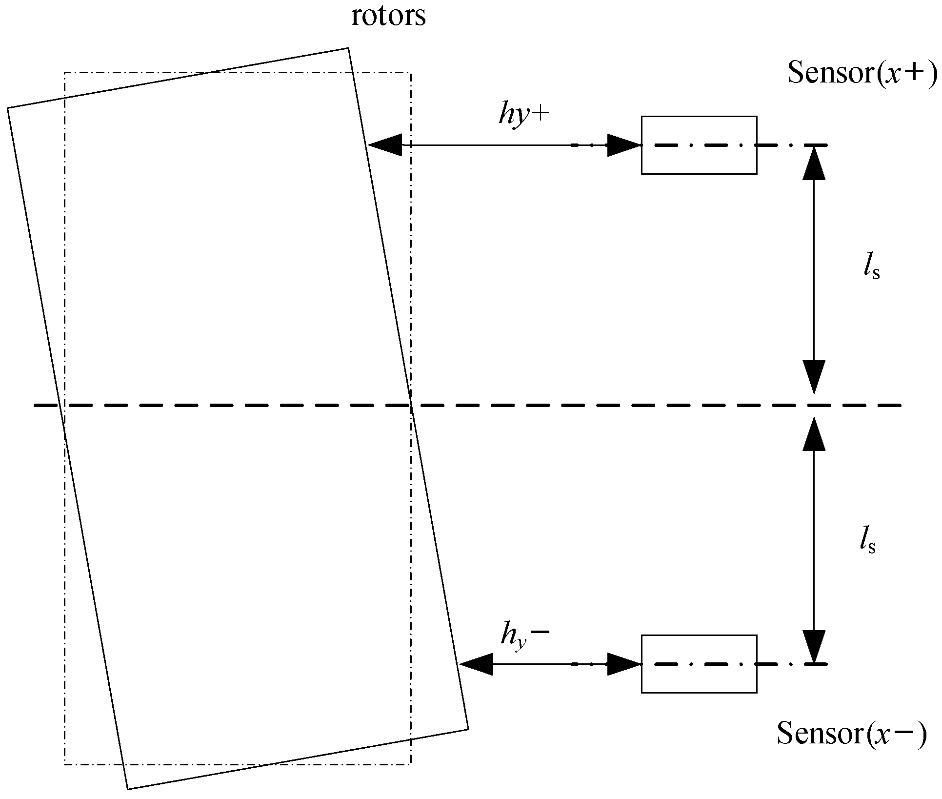
h y + , h y , h x + , h x are the axial displacements of the rotor measured by the axial sensors projected on the y-axis in the positive and negative directions and on the x-axis in the positive and negative directions, respectively. The rotor deflection angle can be obtained by the position difference between two sensors on the same line. Take for example the α channel where the rotor is deflected around the x-axis. The deflection angle of the rotor can be obtained from the ratio of the difference in the position of the rotor at the two ends of the channel to the span between the corresponding sensors. Figure 4 shows a schematic diagram of the deflection angle measurement principle.
The α angle of deflection around the x-axis is calculated as
α = arctan h y + h y 2 l s h y + h y 2 l s
Similarly, the β channel deflection angle for rotor deflection around the y-axis is calculated as
β = arctan h x + h x 2 l s h x + h x 2 l s
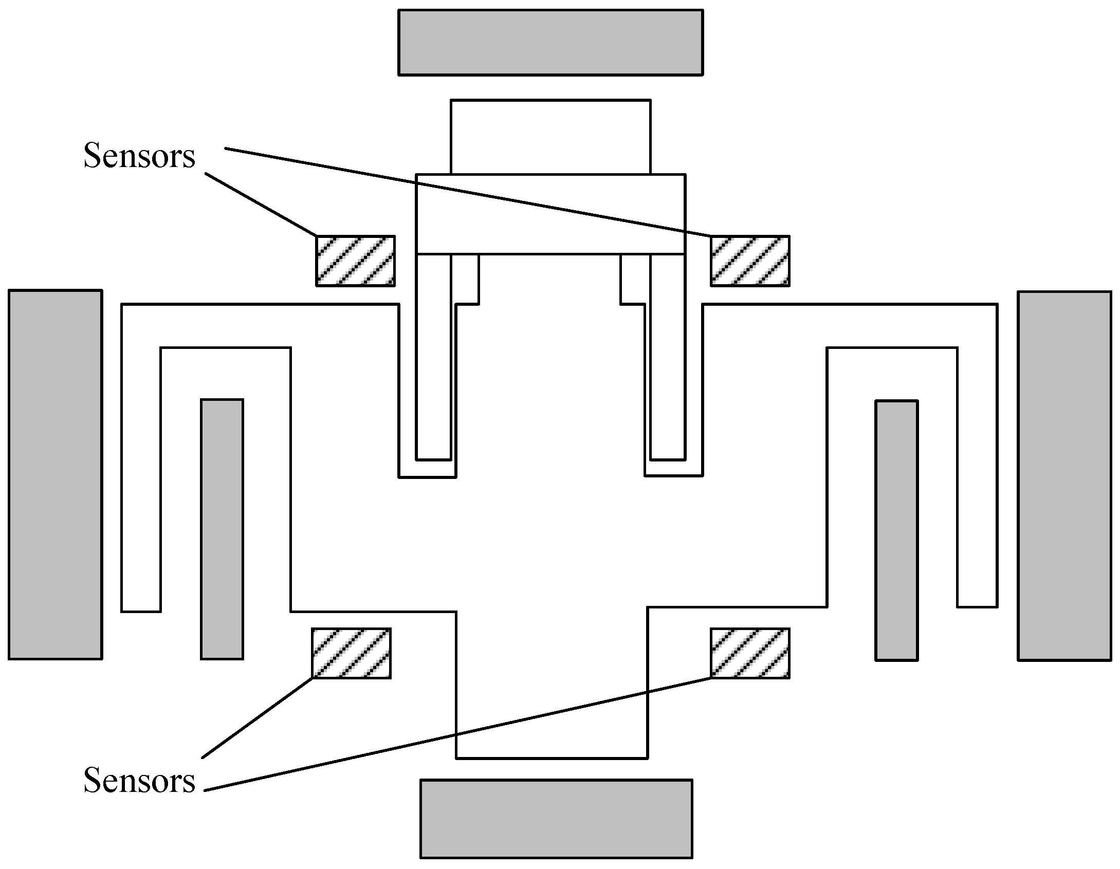
The sensor locations are shown in Figure 5.
The value of α , β can be obtained in real time by collecting the measured values of the displacement sensors in the positive and negative directions of the X , Y -axis:
α = h y + h y 2 l r β = h x + h x 2 l r
l r is the distance from the sensor to the Z -axis. The gyro deflection channel equation is obtained by combining Equation (1) with Equation (2):
J x α ¨ + J z Ω β ˙ = 2 B L D i α J y β ¨ J z Ω α ˙ = 2 B L D i α
From Equations (3)–(5), it can be seen that the deflection angles α and β can be actually measured by the sensor, and because the deflection angles a and b are controlled quantities, the closed-loop control system can be designed so that the difference between the given value and the actual value can be used as the input of the control system, and the output values are the deflection angles α and β . The deflection angles α and β are the outputs of the control system, and the deflection angles α and β are the outputs of the control system. From Equations (2) and (6), the torque of the two degrees of freedom is only related to the currents i α and i β , and the torque is linear with the current. Therefore, the current is used as an intermediate variable, and the deflection angle is controlled by controlling the current.

2.3. Power Amplifier Principle Analysis and Modeling

The MSCSG controller outputs a voltage signal, while the generation of magnetic resistance and Lorentz force in the magnetic bearing requires a current signal, so it is necessary to convert the voltage control signal into the command winding current signal through a power amplifier. In this paper, the MSK541 chip is selected as the power amplifier of the magnetic bearing control system, and the principle is shown in Figure 6. The MSK can withstand a maximum rated voltage of 80 V and can provide a guaranteed continuous output current of up to 5 A, which is very suitable for high-power amplification and this deflection application. Since the linear power amplifier has good linearity characteristics over the rated voltage interval range, the amplifier can be simplified to the form of Figure 6.
From Figure 6, it can be seen that the relationship between coil output current and voltage is satisfied:
L d i ( t ) d t + R i ( t ) = U s a t ( x )
where s a t ( x ) is the voltage saturation measure function that satisfies the relation
s a t ( x ) = x , x < 1 ± 1 , x 1
With the application of a pull-type transformation to Equation (8), the equivalent transfer function of the linear amplifier over the rated voltage range satisfies the relation
g ( s ) = i ( s ) U ( s ) = 1 L s + R
where L and R are the equivalent resistance and inductance of the amplifier link, respectively. An equivalent transformation of the above equation yields
g ( s ) = k a ω a s + ω a
where k is the equivalent amplification and ω is the equivalent cutoff frequency, both of which satisfy k = 1 / R , ω = R / L .
Therefore, the power amplifier can be equivalent to an inertial link, which is connected in series with the MSCSG model. Therefore, when designing the MSCSG closed-loop control system, the two deflection channels are decoupled first, and then the closed-loop control method of the two channels is designed.

3. MSCSG Deflection Channel Decoupling

Here, state variable X = α ˙ β ˙ α β T ; input variable U = u 1 u 2 T = i α i β T ; output variable Y = α β .
The corresponding state-space equations are as follows:
X ˙ = f ( X ) + g ( X ) U Y = C X
and they include the following: C = 0 0 1 0 0 0 0 1 ; f ( X ) = J z Ω J r J z Ω J r x 1 x 2 T ; g ( X ) = 2 B L D J r 0 0 2 B L D J r 0 0 0 0 .
In order to solve for the dynamic inverse of the system, it is necessary to differentiate Y so that it explicitly contains the input variable U . By derivation, we obtain
J ( U ) = y ¨ 1 y ¨ 2 T = 2 B L D J r i α J z Ω J r x 2 2 B L D J r i β + J z Ω J r x 1
Let J be a partial derivative of U to obtain the Jacobi matrix of the system:
J U = 2 B L D J r 0 0 2 B L D J r 0
The determinant of the Jacobi matrix of the system is not zero, so an inverse system of the system exists.
According to the theory of inverse systems, the expression of an inverse system can be obtained by defining a new input variable: φ = φ 1 φ 2 T = y ¨ 1 y ¨ 2 T , replacing y ¨ 1 y ¨ 2 T with a new input variable φ 1 φ 2 T :
U = 1 J U φ + S ( X )
where 1 J U = J r 2 B L D 0 0 J r 2 B L D , S ( X ) = J z Ω 2 B L D J z Ω 2 B L D . By connecting Equation (7) as a state feedback and dynamic compensation decoupling network in series in front of the original system, the system can be transformed into a pseudo-linear system, and the system schematic is shown in Figure 7.
The decoupled gyro system can be viewed as two single-input single-output (SISO) systems, and each SISO system is a second-order system. Considering the uncertain perturbation and unmodelable terms of the deflection angular displacement channel, deflection angular velocity channel and deflection angular acceleration channel, as well as the residual coupling terms in the decoupling process of the inverse system, the system is unified and expressed by the uncertain nonlinear function f ( x ) . Taking the decoupled α channel as an example, this second-order system can be expressed as
x ˙ 1 = x 2 x ˙ 2 = b u + f ( x )
where b is a constant factor and the sign is known.
The schematic diagram of the MSCSG control system is shown in Figure 8. The MSCSG control system mainly consists of a double closed-loop control of a current loop and displacement loop. The forward channel of the current loop consists of a generating current signal, DA module, power amplifier, coil, and other parts. The current signal is calculated and generated by the control chip, converted into a continuous small current drive signal after the DA module, and then amplified into a large current signal, i.e., the drive current of the coil, by the power amplifier. The current flows into the coil and drives the rotor to radial two-degree-of-freedom deflection. The feedback channel of the current loop consists of a current sensor, a conditioning circuit, an AD module, and end processing. The current sensor collects the driving current in the coil, and through the conditioning circuit, the large current signal is conditioned into a small current signal with appropriate range, phase, and other parameters and then converted into a digital signal by the AD module. Finally, the end processing ensures that the digital signal is within the rated operating range of the control chip, which not only improves the accuracy but also protects the chip.
The forward channel of the displacement ring is the same as the forward channel of the current ring. When current is passed through the coil, the rotor is driven to realize radial two-degree-of-freedom deflection. The deflection angular displacement is collected by the displacement sensor and enters the feedback channel. Similar to the current loop, the displacement signal, after signal conditioning and AD conversion, makes a difference with the reference displacement, which is used as the error input of the controller. This dual-loop control structure, with the angular displacement error as input and the deflection angular displacement as output, arranges the current inner loop on the circuit board to ensure the stability of the system. At the same time, the double closed-loop can improve the rapidity of the system so that the angular displacement error quickly converges to 0. In a limited time. The flow of the control method for burning in the control chip is shown in Figure 9.

4. Controller Design

The fuzzy RBF neural network, which combines the arbitrary accuracy nonlinear approximation ability of the RBF neural network and the abstraction ability of fuzzy control for complex linear systems, can significantly improve the dynamic quality of the sliding mode controller. The learning ability of the RBF neural network is introduced to modify the affiliation function and fuzzy rules of fuzzy control, which solves the subjectivity caused by fuzzy control relying too much on an empirical basis. The fuzzy RBF neural network consists of four main parts, which are the input layer, fuzzification layer, fuzzy inference layer, and output layer.
Input layer: Each node in the input layer is directly connected to each component of the input quantity, and for each node i in this layer, the input–output relationship is expressed as
f 1 ( i ) = x i
Fuzzification layer: Each node of the fuzzification layer has the function of the affiliation function, and a Gaussian function is used as the affiliation function:
f 2 ( i , j ) = exp ( n e t j 2 ) n e t j 2 = ( f 1 ( i ) c i j ) 2 b j 2
where b j and c i j are two adjustable parameters, where b j is the width of the Gaussian basis function of the jth neuron, which is a scalar; c i j is the coordinate of the center point of the Gaussian basis function of the jth neuron, which mainly characterizes the Euclidean distance between the input and the center point. The effects of the adjustable parameters b j and c i j on the fuzzification layer can be summarized as follows: the larger b j is, the larger the mapping of the network to the input; the closer c i j is to the input, the more sensitive the Gaussian function is to the input.
Fuzzy inference layer: This realizes the premise inference of rules; each node of this layer is equivalent to a rule. This layer completes the matching of fuzzy rules by connecting with the fuzzification layer, and the output of each node is the product of all the input signals of that node:
f 3 ( j ) = j = 1 N f 2 ( i , j ) N = i = 1 N N i
where N i is the number of the ith input affiliation function in the input layer, i.e., the fuzzification layer node.
Output layer: This realizes reasoning about the premises and conclusions of rules, as well as reasoning between rules:
f 4 ( l ) = w f 3 = j = 1 N w ( l , j ) f 3 ( j )
where l is the number of nodes in the output layer and w is the connection weight matrix between the nodes in the output layer and the nodes in the fuzzy inference layer.
Take y m ( k ) and y ( k ) to be the network output and actual output, respectively. Then take y m ( ) = f 4 , and the inputs of the network x 1 , x 2 denote u ( k ) and y ( k ) , respectively. Then, take the approximation error of the network to be
e ( k ) = y ( k ) y m ( k )
The gradient descent method is used to correct the adjustable parameters, and the objective function is defined as
E = 1 2 e ( k ) 2
The output layer weighting adjustment approach is
Δ w ( k ) = η E w = E e e y m y m w = η e ( k ) f 3
A weight learning method for the output layer is
w ( k ) = w ( k 1 ) + Δ w ( k ) + α ( w ( k 1 ) w ( k 2 ) )
where η is the learning rate and α is the momentum factor, η , α ( 0 , 1 ) .
The design sliding mode function is
s = c e + e ·
In the formula, c > 0 , and
s · = c e · + e · · = c e · + b σ u c + f ( x ) x d · · = c e · + β u c + f ( x ) x d · ·
where β = b σ ; λ = 1 β is taken, and the Lyapunov function is designed as
V = 1 2 s 2 + β 2 γ λ 2 + 1 2 γ W T W
where λ = λ λ , γ > 0 , obtained by derivation of Equation (26):
V · = s s · + β γ λ λ · 1 γ W T W · = s ( c e · + β u c + f ( x ) x d · · ) + β γ λ λ · 1 γ W T W ·
Taking α = k s + c e · + f ( x ) x d · · + η sgn s , k > 0 , η ε N , Equation (26) can be further expanded as
V · = s ( α k s + β u c + f ( x ) η sgn s ) + β γ λ λ · 1 γ W T W · = s ( α k s + β u c + ε η sgn s ) + β γ λ λ · + W T ( s h ( x ) 1 γ W · )
Control laws and adaptive laws are designed for
u c = λ ^ α λ ^ ˙ = γ s α sgn b W ^ ˙ = γ s h ( x )
They are expanded as
V · = s ( α k s β λ α + ε η sgn s ) + β γ λ γ s α sgn β = s ( α k s β λ α ) + β s α λ = s ( α k s β α λ + ε ) k s 2 0
Since V 0 , V · 0 , V is bounded. When t , s 0 , and thus e 0 ,   e · 0 . In summary, the MSCSG control system principle is shown in Figure 10. In order to make the MSCSG two-degree-of-freedom angular displacement output have high accuracy, the error input method is used, and the difference between the reference displacement and the actual displacement is used as the input signal of the system. The error input signal enters the adaptive controller and passes through the sliding mode surface, adaptive law, and control law to output the control signal to the original system. However, there is strong coupling in the original system, so the inverse system decoupling is added between the original system and the controller, i.e., the control signal Is output to the Inverse system decoupling module, which outputs the decoupling control signal to the original system. This decoupling control signal is calculated by the control chip, which outputs it to the hardware circuit. The hardware circuit consists of DA, a power methodology module, which first converts the digital signal output from the control chip into an analog signal and then amplifies the analog signal into the actual current signal in the coil. When the decoupling control current is passed in the coil, the original MSCSG system is driven to output the angular displacement signal. In order to improve the system rapidity and reduce the time lag influence of the hardware circuit (mainly the power amplifier), a current loop closure is set in the middle of the inverse system decoupling module and the actual system. The feedback loop of the current loop consists of three parts: the power amplifier, the conditioning circuit, and the AD, which is processed at the end to make a difference with the decoupling control system output from the inverse system decoupling module, and is used as the error input signal of the hardware circuit. The power amplifier in the feedback loop reduces the large current signal in the coil to a small current signal that the chip can withstand, and the conditioning circuit adjusts the small current signal to the appropriate operating range of the chip, and then the analogue signal is converted to a digital signal by the AD, which can be used as the error input with the difference of the decoupling control signal output from the inverse system decoupling module.

5. Simulation Analysis

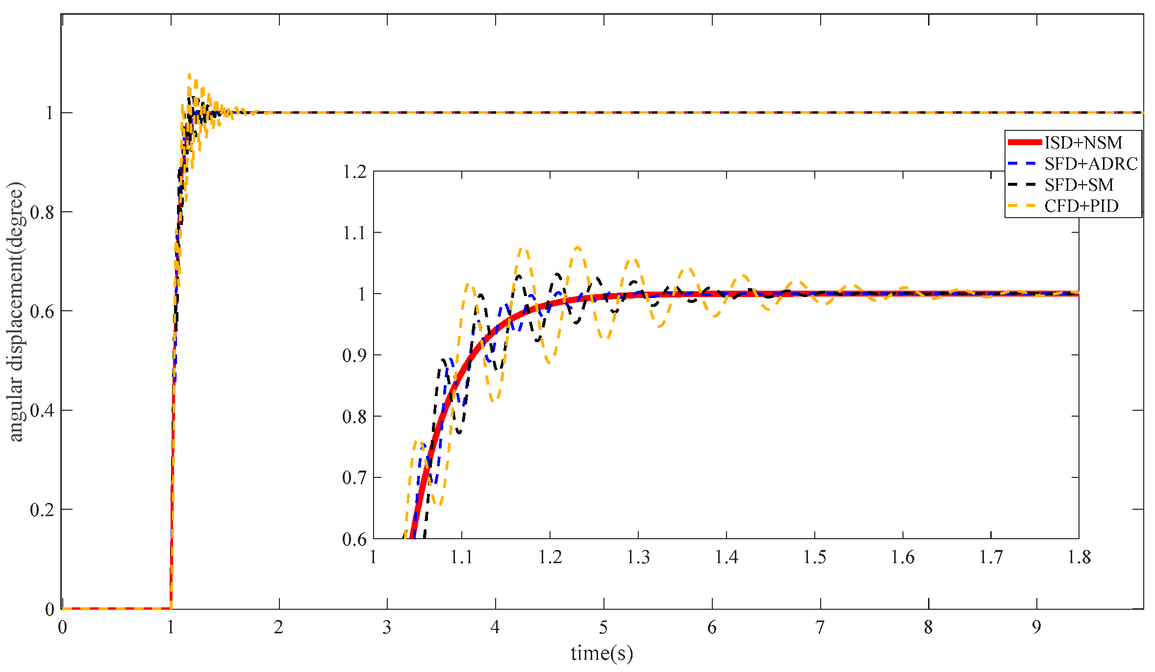
In order to verify the effectiveness of the inverse system decoupling method, and the superiority of the adaptive control method based on fuzzy RBF neural network, the method of this paper and the self-resistant + cross-feedback decoupling, feed-forward decoupling inner-mode control comparative simulation. The MSCSG system parameters and the control system simulation parameters are shown in Table 1 and Table 2. In this paper, three control groups are used, namely, cross-feedback decoupling + PID (CFD), state feedback decoupling (SFD) + sliding mode control (SM), state feedback decoupling + self-resistant control (ADRC), and Inverse system decoupling (ISD) + Neural network sliding mode control (NSM) designed in this paper to verify the effectiveness of this method. In order to intuitively reflect the superiority of the design method in this paper, in the simulation analysis, the main focus is on the tracking ability of the signal and the size of the error, the tracking ability is mainly reflected in the rapidity, i.e., whether it is possible to quickly follow the input signal changes; the error is mainly concerned with the dynamic error and the steady-state error, i.e., whether there is a large perturbation during the dynamic process, and whether there is a much smaller steady state error after stabilisation.

5.1. Simulation Analysis of Decoupling Capability

In Figure 11, when t = 1 s, a −1° step signal is input to the α channel and a 1° step signal is input to the β channel, respectively. As can be seen in Figure 12, the cross-feedback decoupling + PID control and state feedback decoupling sliding mode control, the two channels will produce a coupling of 0.05° to 0.1°, the state feedback decoupling + self-impedance control of the two-channel coupling is smaller, about 0.05°, but the rapidity of the poor, and in the stabilization of the process of the coupling generated by about 5% of the jump. While the inverse system decoupling + neural network sliding mode control has good rapidity, and the use of fuzzy inference layer effectively eliminates the jitter brought about by the sliding mode control, although there exists a steady state error of about 0.02° from t = 3.1 s to t = 3.3 s, but there is no coupling jump, and the fastest system to reach a stable situation without static difference.
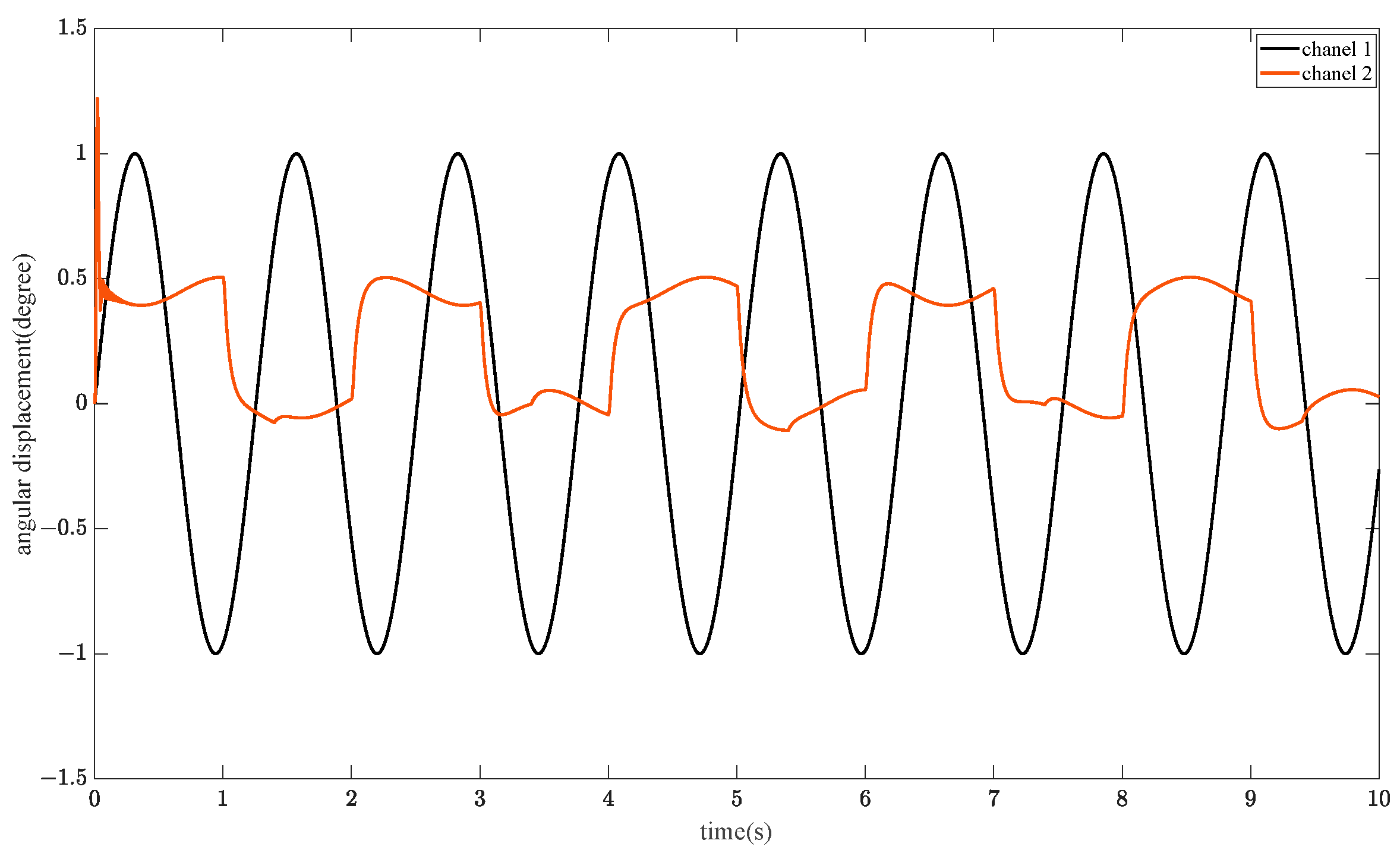
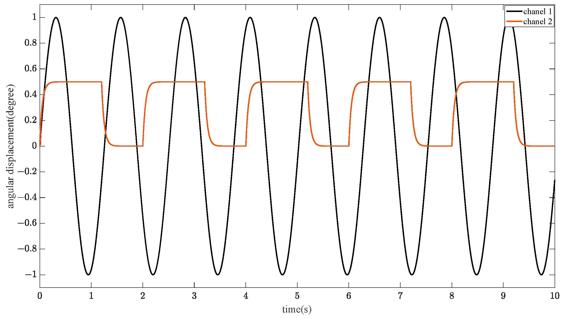
To further verify the decoupling performance, the input angular shift was changed. The input of the α channel is changed to sin 5 t , and the input of the β is a square wave signal with a peak value of 0.5°, a period of 2 s, and a duty cycle of 70%.
Figure 13, Figure 14, Figure 15 and Figure 16 show the cross-feedback decoupling + PID control, state-feedback decoupling + sliding-mode control, state-feedback decoupling + self-resistant control, and inverse-system decoupling + neural-network sliding-mode control, respectively. From Figure 13, the cross-feedback decoupling + PID control decouples the signals of the two channels, there are still residual coupling terms, the continuous signal of the α channel has less impact, while the square wave signal of the β is affected by the residual coupling terms because of the continuous step, and the waveform reproduction is not obvious, and there is a maximum of about 20% of the error, and overshooting is obvious at t = 0, which is a big impact on the system. Figure 14 shows that the state feedback decoupling + sliding mode control at t = 0 to t = 1 s, the coupling jump is larger, and the square wave signal at the step, there is the impact of incomplete decoupling, waveform reproduction is incomplete, there is still about 5% error. For easy observation, the dashed line in the figure is 0.5. Figure 15 shows that the state feedback decoupling + self-resistant control of the waveform reproduction is better than the first two methods, but at t = 0 to t = 1 s, there is a certain coupling jump, when the system is stable, the coupling jump disappears, and the output curve is smooth, but the self-resistant controller is incomplete compensation of the coupling term, resulting in the transition of the system to compensate for the system or compensation is insufficient, and there still exists a static error of 1% to 2%. Figure 16 shows that the inverse system decoupling + neural network sliding mode control output curve is smooth, because the neural network can arbitrarily approximate the disturbance term, and then use the fuzzy control to correct the neural network, so the signal tracking is completed faster when the signal is input. As for the dual-channel coupling, the neural network implicit layer output, the correction of the fuzzy rule and the correction of the sliding mode control can correct the coupling term, and complete the decoupling quickly and well, which improves the rapidity by about 55.7% over the traditional method.

5.2. Anti-Interference Capability Analysis

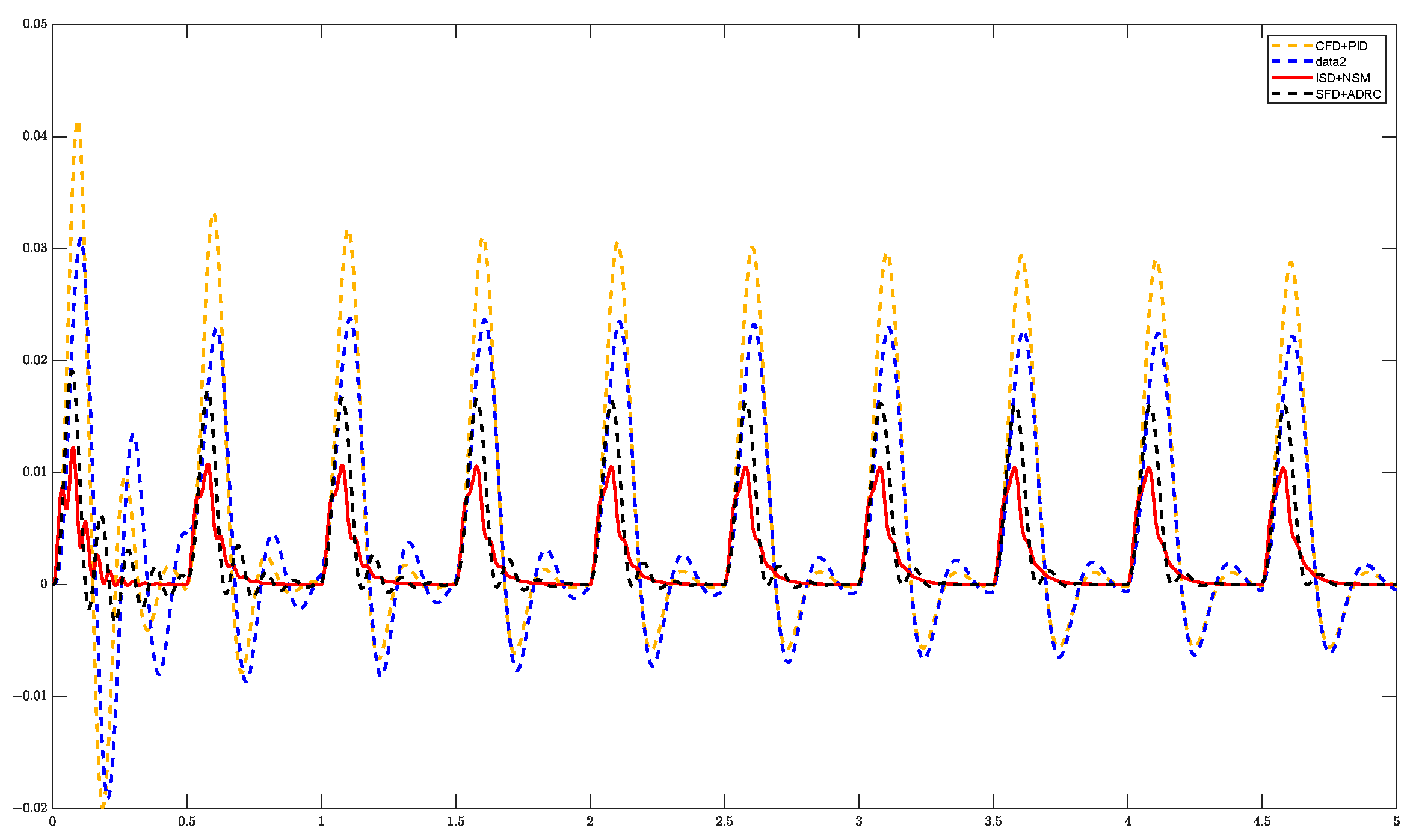
In order to verify the anti-interference ability of this method and check the decoupling effect at the same time, the input signals of the two channels are set to 0, and two kinds of perturbation signals are applied to the two channels respectively, so that the anti-interference performance of various control methods can be compared by comparing the output signals. Figure 17 shows that, after applying the perturbation signal of sin ( 10 π t ) to the α channel, the cross-feedback decoupling + PID control produces a reciprocating homodyne deflection of about 0.1°; the state-feedback decoupling + sliding-mode control produces a reciprocating deflection of about 0.05°, but because it is difficult for the sliding-mode control to eliminate the jitter, the amplitude of perturbation of the various cycles is not the same; the state-feedback decoupling + self-improvement control produces a homodyne reciprocating deflection of about 0.03°. same-frequency reciprocal deflection. Compared with the above three methods, the perturbation output of the inverse system decoupling + neural network sliding mode control is maintained within 0.01°, and the curve is smooth without the influence of high-frequency jitter vibration, which can better suppress the interference of low-frequency signals.
As shown in Figure 18, when the perturbation signal of sin ( 100 π t ) is applied to the α channel, the cross-feedback decoupling + PID control produces a reciprocal deflection of about 0.1°, but because of the poor rapidity of this method, the difference between the perturbation amplitudes in each cycle is large, and the maximum perturbation is difficult to predict; the state-feedback decoupling + sliding-mode control, because of the difficulty in eliminating the influence of jitter vibration, the amplitude of the cycle jumps, and the overall maintenance is 0.08° to 0.1°. The state feedback decoupling + self-resistant control produces about 0.02° of reciprocal deflection, but the rapidity is poor, and the error tends to stabilize after t = 3 s, and the amplitude jumps drastically from t = 0 to t = 3 s, which is difficult to estimate. The reciprocal deflection of the inverse system decoupling + neural network sliding mode control is maintained within 0.01°, and the amplitude is stable, the curve is smooth, and the suppression level of the continuous interference signal has a greater progress compared with the traditional method.
As shown in Figure 19, a square wave signal is applied to the β channel with an amplitude of 1, a period of 0.5 s and a duty cycle of 30%. The cross-feedback decoupling + PID control produces a disturbed deflection of 0.05° and a negative direction deflection of 0.01°; the state-feedback decoupling + sliding mode control reduces the disturbed deflection to 0.03°, but because of the jitter is difficult to be eliminated, the positive and negative deflections seen in the two cycles and the positive and negative traversal times are many; the state-feedback decoupling + self-impedance control produces a disturbed deflection of about 0.02° but the disturbed signal is just When applied, the self-immobilizing controller estimates the disturbance slowly and with a large error, producing an impulse shock of about 0.05°. The inverse system decoupling + neural network sliding mode control designed in this paper has a small sample size when the perturbation is just applied, and the three-layer structure of the neural network does not estimate the perturbation sufficiently, so there is a certain vibration before t = 0.5 s. However, when the sample size is sufficient, the controller’s suppression capability of the perturbation becomes stronger, and the perturbed deflection is suppressed to about 0.01°, and there is no negative directional deflection. It can be seen that the present method suppresses the perturbation signal better than the conventional controller.
As shown in Figure 20, a square wave signal is applied to the β channel with an amplitude of 1, a period of 0.1 s and a duty cycle of 75%. Compared with the input signal of Figure 19, the short period has a high duty cycle and is closer to a continuous signal. Therefore the perturbed deflections of the methods of Figure 20 are closer to the continuous signal and the step is not significant. Same as above, the perturbed deflection of cross-feedback decoupling + PID control and state-feedback decoupling + sliding-mode control, state-feedback decoupling + self-resistant control are 0.05°, 0.03° and 0.02°, respectively, and that of the inverse-system decoupling + neural-network sliding-mode control designed in this paper is about 0.01°. In summary, the inverse system decoupling + neural network sliding mode control can well suppress the perturbed signal under continuous and discrete signals.

6. Experimental Verification

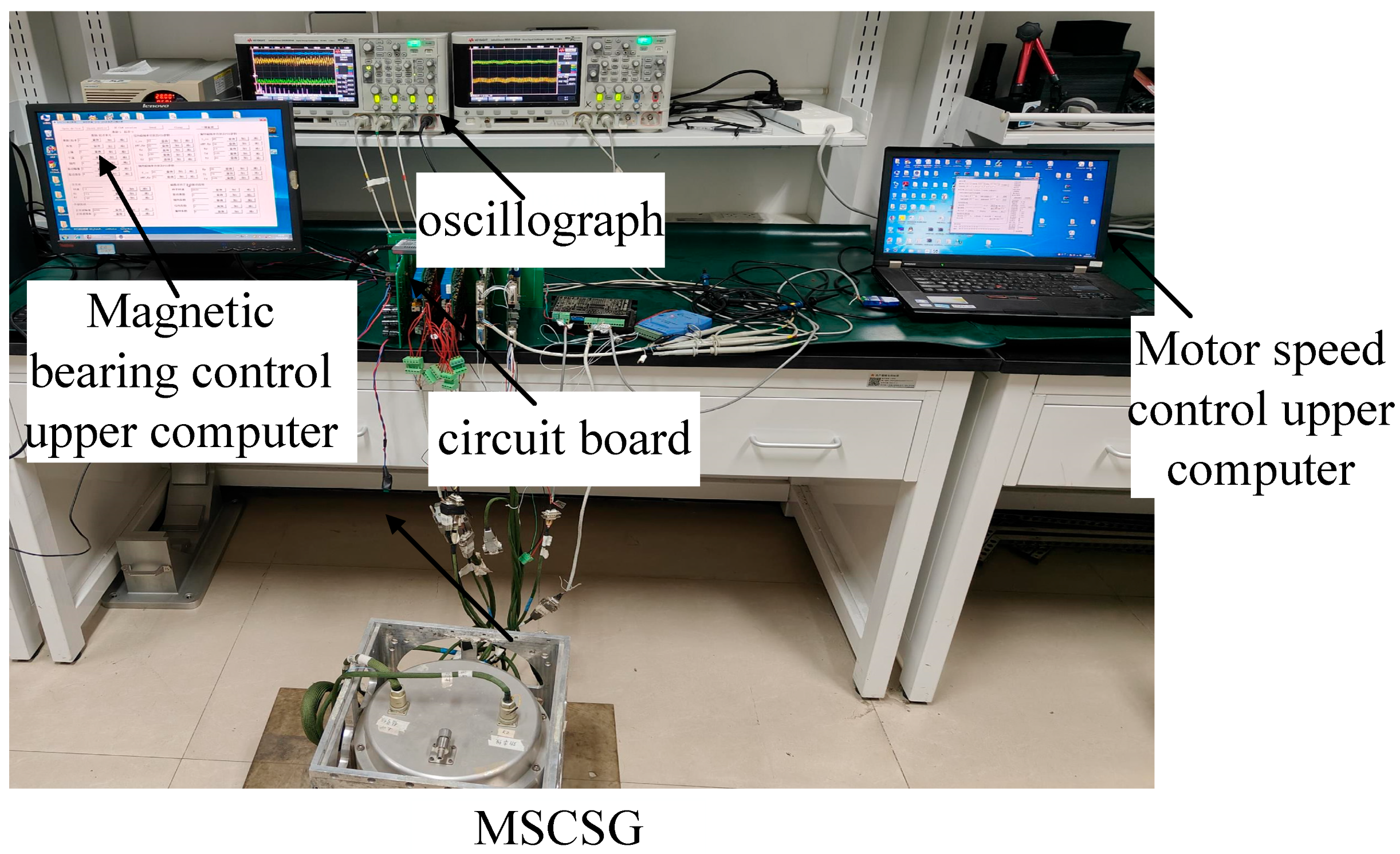
The MSCSG experimental system is shown in Figure 21. The experimental system mainly consists of MSCSG, oscilloscope, control circuit board, magnetic bearing control upper unit and motor speed control upper unit. There are two oscilloscopes, the left side shows axial motion signals and the right side shows signals of deflection in two degrees of freedom. The motor speed control upper computer, is mainly responsible for adjusting the rotational speed of the gyro rotor, when the rotational speed is rated, and then through the magnetic bearing control upper computer, to adjust the parameters of each magnetic bearing control, to verify the performance of each channel. The rotor speed is set to 5000 revolutions per minute for this experiment. The experiment was carried out with the rotor speed set at 3000 revolutions per minute and the ratio of resistance inside and outside the power amplifier at 49.

6.1. Experimental Verification of Decoupling Performance

The eddy current sensor used in this experiment characterizes the angular displacement of the deflection channel in terms of voltage, i.e., the vertical coordinate in the figure. The range of voltage is 0–3 V, and the deflection angular displacement is ± 0.3 , which corresponds linearly. The horizontal coordinate is time, it should be noted that the sampling frequency of this experiment is 100 Hz, and the horizontal coordinate indicates the number of times, sampling 2000 times, i.e., running 20 s.
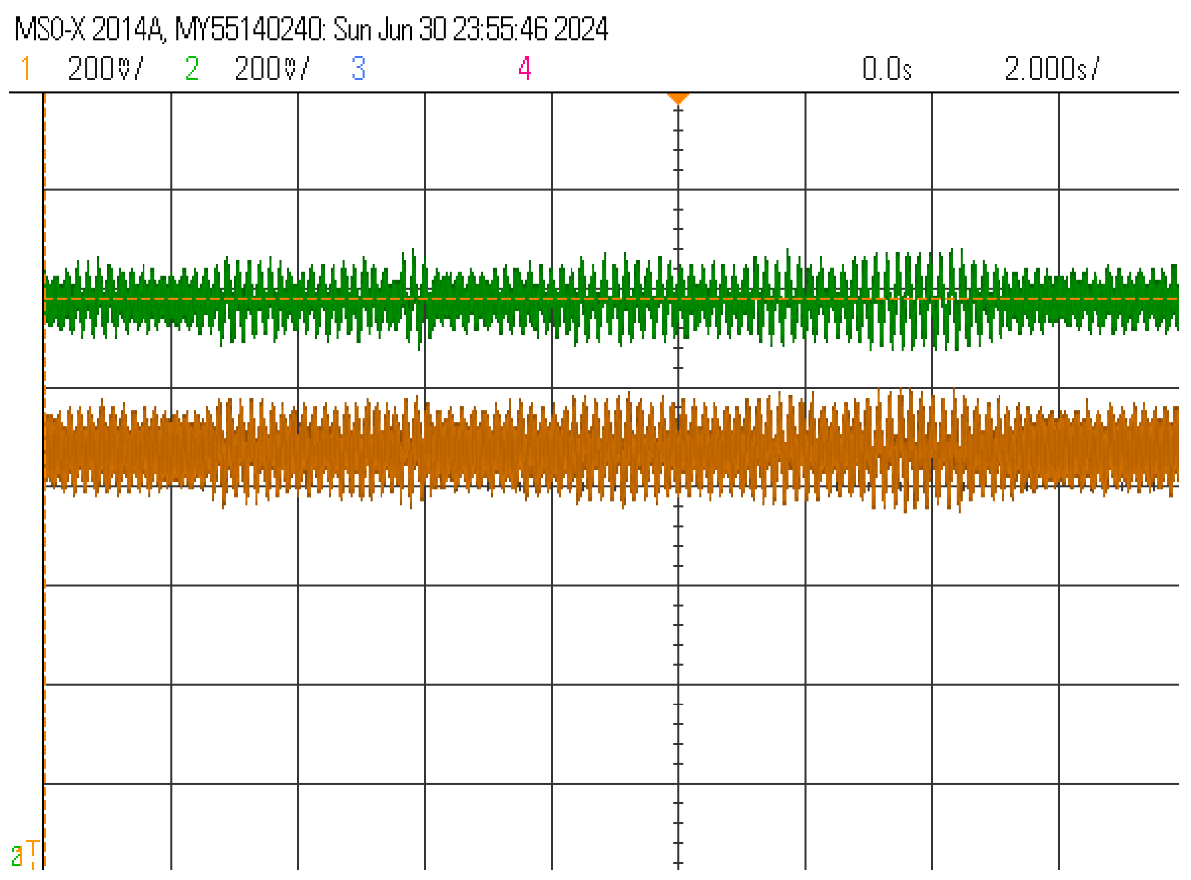
Therefore, the deflection of the two channels in the equilibrium position, the oscilloscope voltage is 1.5 V, that is, the deflection angular displacement of 0. Figure 22 shows the deflection channel after the application of the two continuous signal, the angular displacement of the output signal. The original screen of the oscilloscope is shown in Figure 23. The analysis shows that the difference between the mean values of the voltages of the two channels under the same input signal is 0.002 V, which accounts for 0.13% of the 1.5 V operating voltage, which is negligible. It can be seen that the two deflection channels are not coupled.

6.2. Verification of Anti-Interference Performance

To verify the anti-jamming performance of MSCSG and the design method in this paper, three sets of experiments are set up; continuous signal perturbation, pulse signal perturbation and two-channel different signal perturbation, respectively. As shown in Figure 24, the initial input signal is 0, and unknown but identical perturbation signals are added to the two channels, under the continuous signal perturbation, the accumulation of the perturbation on the deflection angular displacement reaches the peak at t = 800 (t = 8 s), and then it returns to normal at t = 1200 (t = 12 s), and there is no interference between the two channels with each other. Figure 25 shows the original signal of the oscilloscope, it can be seen that the two channels, although the decoupling effect is very good, but in a long time under the accumulation of perturbation, the output signal still has a certain difference, but the RBF neural network can quickly approximate the unknown perturbation, and will be and compensate for the perturbation signal on the deflection channel interference.
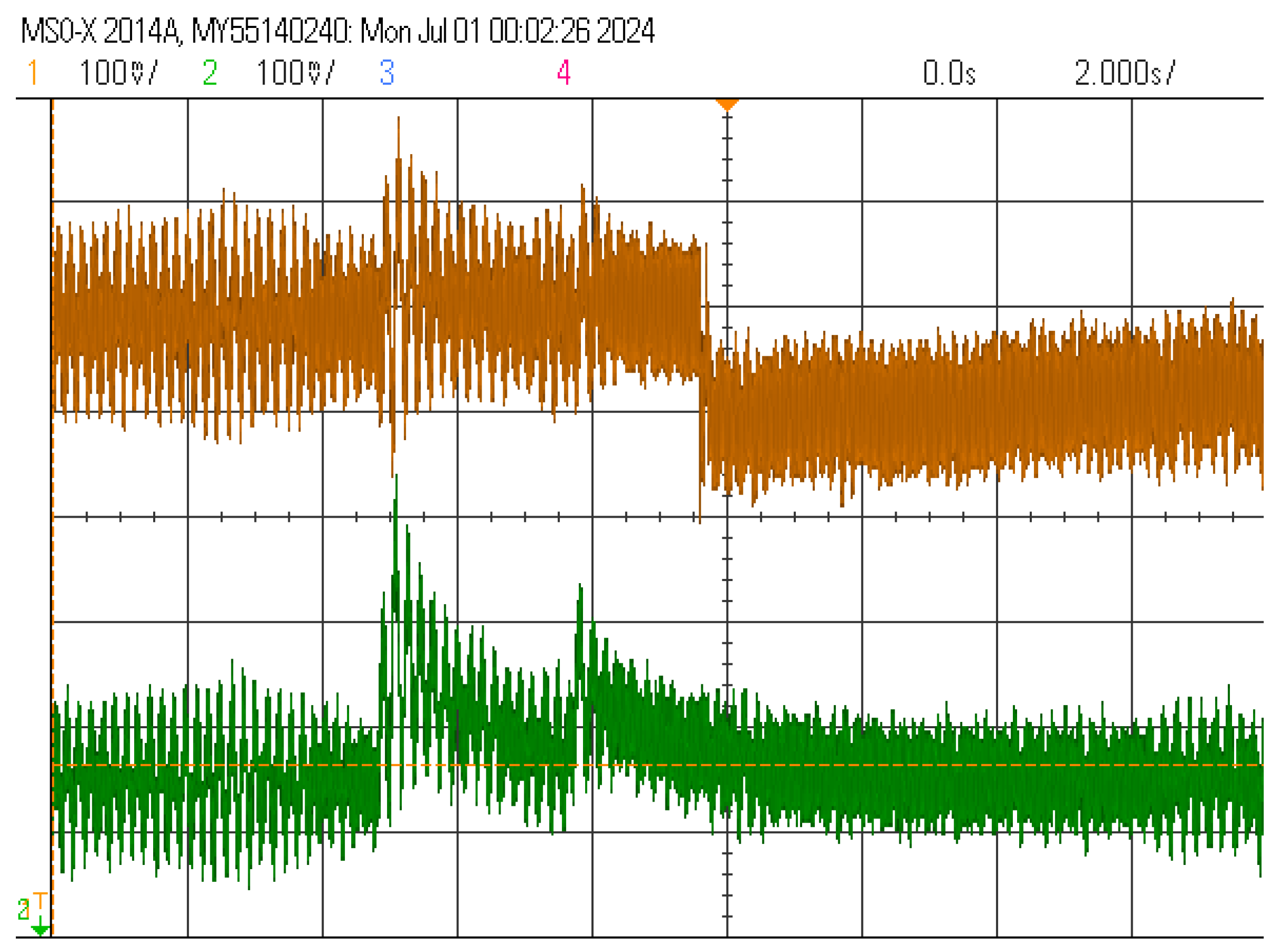
In order to verify the anti-disturbance ability to the pulse disturbance signal, an identical pulse signal was applied at t = 500 (t = 5 s), respectively, and in order to make the experimental effect intuitive, the balance position of the two channels was changed in this experiment, as shown in Figure 26, and the balance positions of the two channels were set to 1.45 V and 1.55 V. From the experimental results, it can be seen that, in the different balance positions, applying the same pulse disturbance, both of which can compensate the disturbance to the deflection angle in a short time. Moreover, the peak value of the impact of the pulse disturbance on the deflection channel is different at different equilibrium positions, reaching 2 V (0.09°) in the right figure and only 1.75 V (0.06°) in the left figure, but both of them can be compensated well in a short time. Figure 27 shows the raw picture of the oscilloscope under a pulsed perturbation signal.
In order to verify the anti-interference ability of the two channels under complex signals, this experiment applies a step signal within one channel, starting at t = 0, and adjusts the equilibrium position to 1.45 V in order to visualize the experimental effect. Two pulse signals are applied in the order one channel, and the equilibrium position is kept unchanged. As shown by the experimental results in Figure 28, the step signal has a larger effect on a single channel and is easy to excite a pulse, but it can quickly compensate for the step perturbation and return to the equilibrium position at t = 1000 (t = 10 s); two consecutive pulsed signals, which can be compensated for in a very short period of time and compared with the pulsed perturbation in Figure 26, the second pulsed perturbation signal in this experiment was applied before returning to the equilibrium position, and the second pulsed perturbation signal is applied at the equilibrium position. However, it did not cause the excitation of a larger deflection angle. Combining the left and right graphs, after the input of different perturbation signals in the two channels, it can quickly return to the equilibrium position, and there is no subsequent effect after the equilibrium, which further verifies the decoupling performance. Figure 29 shows the original signal of the oscilloscope, the experimental effect is more intuitive.

7. Conclusions

  • For the structure and working principle of MSCSG, establish a two-degree-of-freedom deflection channel model, and the equations show that there is a serious coupling between the two deflection channels; model and analyse the power amplifier, and equate it to an inertial link. Design the inverse system decoupling method, and use the fuzzy method to improve the RBF neural network to compensate the uncertain perturbation and residual coupling term; design the adaptive sliding mode controller, and based on the Lyapunov stability criterion, the controller is proved to converge.
  • Simulation analysis shows that the method designed in this paper, relative to the traditional method, has a large improvement in decoupling effect and anti-jamming performance; the validity of this method is subsequently verified by experiments.
  • The main principle of the fuzzy RBF neural network designed in this paper is to use the abstraction ability of the fuzzy method to the natural language to correct the sliding mode controller and improve the dynamic quality; in the actual experiments, the rules of the fuzzy method are set up by ourselves according to the accumulation of experience in the previous many experiments, which may not be the optimal rules, but the introduction of the learning ability of the RBF neural network to correct the fuzzy control’s subordinate degree function and fuzzy rules, which solves the subjectivity caused by fuzzy control relying too much on the empirical basis. In brief, it means that the fuzzy rules can be gradually narrowed down by correcting the fuzzy rules one by one while keeping the parameters of the RBF neural network unchanged; on the contrary, after optimising the rule intervals, the parameters of the RBF neural network can be corrected again until the experimental results are better.
  • In the future, the fuzzy rules and RBF neural network can be derived in the more underlying logic, and strive to introduce adaptive methods into the two, parameter optimisation and rule correction on the form of indicators to reflect the use of optimisation methods to find the optimal parameters and rules.

Author Contributions

Conceptualization, F.C.; writing—original draft preparation, F.C.; formal analysis, W.W.; data curation, C.Y.; validation, S.W.; writing—review and editing, W.Z. All authors have read and agreed to the published version of the manuscript.

Funding

The national natural science foundation of China, 52075545.

Data Availability Statement

Data derived from public domain resources.

Conflicts of Interest

The authors declare no conflict of interest.

References

  1. Han, S.-F.; Qin, C.; Xu, A.-P.; Xu, Z.-B. Research on the Reverse Sliding Mode Control Strategy of Photoelectric Tracking Rotary Table; Electronics Optics & Control: Changchun, China, 2023. [Google Scholar]
  2. Ning, X.; Han, B.-C.; Fang, J.-C. Disturbance Observer Based Decoupling Method of Double-gimbaled Variable Speed Control Moment Gyroscope. J. Mech. Eng. 2017, 53, 52–59. [Google Scholar] [CrossRef]
  3. Jiang, C. Research on Control Strategy of Turntable Servo System Based on RBF Neural Network. Master’s Thesis, Beijing Jiaotong University, Beijing, China, 2022. [Google Scholar]
  4. Lin, Z.-C. Research on the Control System of Maglev Dual-Stage Inertially Stabilized Platform. Ph.D. Thesis, National University of Defense Technology, Changsha, China, 2015. [Google Scholar]
  5. Xia, C.; Cai, Y.; Ren, Y.; Wu, D.; Wang, Y. Feedforward decoupling and internal model control for rotor of magnetically suspended control and sensing gyroscope. J. Beijing Univ. Aeronaut. Astronaut. 2018, 44, 480–488. [Google Scholar]
  6. Ren, Y.; Chen, X.; Cai, Y.; Wang, W.; Liu, Q. Adaptive robust sliding mode simultaneous control of spacecraft attitude and micro-vibration based on magnetically suspended control and sensitive gyro. Proc. Inst. Mech. Eng. Part G J. Aerosp. Eng. 2020, 234, 2197–2210. [Google Scholar] [CrossRef]
  7. Yin, Z.; Cai, Y.; Ren, Y. Decoupled active disturbance rejection control method for magnetically suspended rotor based on state feedback. J. Beijing Univ. Aeronaut. Astronaut. 2021, 48, 1210–1221. [Google Scholar]
  8. Li, L.; Ren, Y.; Chen, X.; Wang, W. Design of MSCSG control system based on ADRC and RBF neural network. J. Beijing Univ. Aeronaut. Astronaut. 2020, 46, 1966–1972. [Google Scholar]
  9. Su, X.; Yang, X.; Xu, Y. Fuzzy adaptive terminal sliding mode control based on recurrent neural network compensation for a maglev system. Eng. Appl. Artif. Intell. 2023, 124, 106588. [Google Scholar] [CrossRef]
  10. Zhang, J.; Mei, X.; Zhang, D.; Jiang, G.D.; Liu, Q. Application of decoupling fuzzy sliding mode control with active disturbance rejection for MIMO magnetic levitation system. Proc. Inst. Mech. Eng. Part C J. Mech. Eng. Sci. 2013, 227, 213–229. [Google Scholar] [CrossRef]
  11. Mao, W.-L.; Chu, C.-T. Modeless Magnetic Bearing System Tracking Using an Adaptive Fuzzy Hermite Neural Network Method. IEEE Sens. J. 2019, 19, 5904–5915. [Google Scholar] [CrossRef]
  12. Jiang, C.; Zhu, H.; Wang, H. Decoupling Control of Outer Rotor Coreless Bearingless Permanent Magnet Synchronous Generator Based on Fuzzy Neural Network Inverse System. IEEE Trans. Transp. Electrif. 2023, 9, 3908–3917. [Google Scholar] [CrossRef]
  13. Qiu, Z.; Chen, S. Vibration control of a translational coupled double flexible beam system using sliding mode neural network fuzzy control. Trans. Inst. Meas. Control 2022, 44, 2246–2288. [Google Scholar] [CrossRef]
  14. Li, Z. Neural network identifier-based dynamic decoupling control of a novel permanent magnet spherical actuator. Int. J. Model. Identif. Control 2011, 13, 162–170. [Google Scholar] [CrossRef]
  15. Bai, C.; Chen, J.; Ren, Z.; Li, Q.D.; Xiong, Z.H. Adaptive decoupling control of hypersonic vehicle using fuzzy-neural network observer. Proc. Inst. Mech. Eng. Part G (J. Aerosp. Eng.) 2016, 230, 1216–1223. [Google Scholar] [CrossRef]
  16. Huang, Z.; Zhu, J.; Shao, J.; Wei, Z.; Tang, J. Recurrent neural network based high-precision position compensation control of magnetic levitation system. Sci. Rep. 2022, 12, 11435. [Google Scholar] [CrossRef] [PubMed]
  17. Fatemimoghadam, A.; Toshani, H.; Manthouri, M. Control of magnetic levitation system using recurrent neural network-based adaptive optimal backstepping strategy. Trans. Inst. Meas. Control 2020, 42, 2382–2395. [Google Scholar] [CrossRef]
  18. Zhang, Y.; Zheng, Z.; Zhang, J.; Yin, L. Research on PID Controller in Active Magnetic Levitation Based on Particle Swarm Optimization Algorithm. Open Autom. Control Syst. J. 2015, 7, 1870–1874. [Google Scholar]
  19. Chen, S.-C.; Nguyen, V.-S.; Le, D.-K.; Nam, N.T.H. Nonlinear Control of an Active Magnetic Bearing System Achieved Using a Fuzzy Control with Radial Basis Function Neural Network. J. Appl. Math. 2014, 2014, 272391. [Google Scholar] [CrossRef]
  20. Chiang, G.-K.; Chu, C.-T.; Lin, T.-C. Adaptive sliding mode recurrent fuzzy neural network estimator in magnetic bearing system. Appl. Mech. Mater. 2014, 543–547, 1487–1491. [Google Scholar] [CrossRef]
  21. Wang, S.; Zhu, H.; Wu, M.; Zhang, W. Active Disturbance Rejection Decoupling Control for Three-Degree-of- Freedom Six-Pole Active Magnetic Bearing Based on BP Neural Network. IEEE Trans. Appl. Supercond. 2020, 30, 3603505. [Google Scholar] [CrossRef]
  22. Supreeth, D.K.; Bekinal, S.I.; Shivamurthy, R.C. Optimization of Radial Electrodynamic Bearing Using Artificial Neural Network. IEEE Access 2024, 12, 67957–67970. [Google Scholar] [CrossRef]
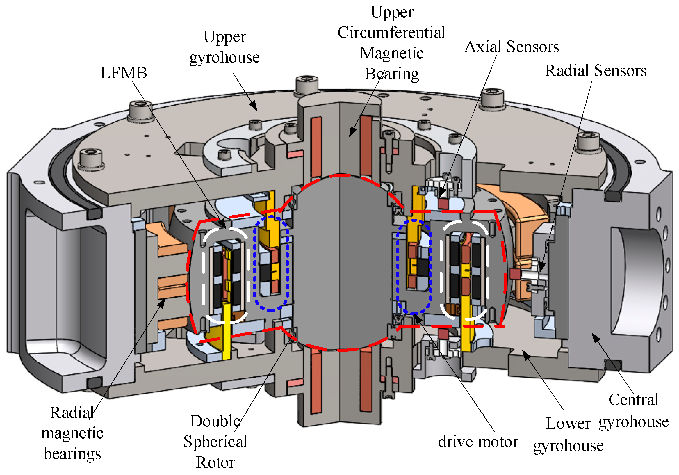
Figure 1. MSCSG structure diagram.
Actuators 13 00302 g001
Figure 2. Sensor schematic diagram.
Actuators 13 00302 g002
Figure 3. Stator coordinate system diagram.
Actuators 13 00302 g003
Figure 4. Schematic diagram of the deflection angle measurement principle.
Actuators 13 00302 g004
Figure 5. Sensor position diagram.
Actuators 13 00302 g005
Figure 6. Linear power amplifier principle.
Actuators 13 00302 g006
Figure 7. Schematic diagram of the inverse system.
Actuators 13 00302 g007
Figure 8. Schematic diagram of single control method.
Actuators 13 00302 g008
Figure 9. Control method flow chart.
Actuators 13 00302 g009
Figure 10. MSCSG Control System Schematic.
Actuators 13 00302 g010
Figure 11. α channel decoupled deflection angle signal.
Actuators 13 00302 g011
Figure 12. β channel decoupled deflection angle signal.
Actuators 13 00302 g012
Figure 13. Cross-feedback decoupling + PID control angular displacement.
Actuators 13 00302 g013
Figure 14. State-feedback decoupling + sliding-mode control angular displacement.
Actuators 13 00302 g014
Figure 15. State-feedback decoupling + self-resistant control angular displacement.
Actuators 13 00302 g015
Figure 16. Inverse-system decoupling + neural-network sliding-mode control angular displacement.
Actuators 13 00302 g016
Figure 17. Anti-jamming performance of α channel under sin ( 10 π t ) signal.
Actuators 13 00302 g017
Figure 18. Anti-jamming performance of α channel under sin ( 100 π t ) signal.
Actuators 13 00302 g018
Figure 19. Anti-interference performance of β channel under low-frequency square-wave signals.
Actuators 13 00302 g019
Figure 20. Anti-interference performance of β channel under high-frequency square wave signals.
Actuators 13 00302 g020
Figure 21. MSCSG Experimental System.
Actuators 13 00302 g021
Figure 22. Decoupled Performance Verification.
Actuators 13 00302 g022
Figure 23. Oscilloscope Raw Signal.
Actuators 13 00302 g023
Figure 24. Dual-channel deflection signal under continuous signal perturbation.
Actuators 13 00302 g024
Figure 25. Raw Oscilloscope Picture under Continuous Disturbance Signal.
Actuators 13 00302 g025
Figure 26. Pulse Disturbance Signal Dual Channel Deflection Signal.
Actuators 13 00302 g026
Figure 27. Raw oscilloscope image under pulsed disturbance signal.
Actuators 13 00302 g027
Figure 28. Complex Disturbance Signal Dual Channel Deflection Signal.
Actuators 13 00302 g028
Figure 29. Raw Oscilloscope Image under Complex Perturbation Signal.
Actuators 13 00302 g029
Table 1. System parameters.
ParametersValue
Jx/(kg·m2)0.0097
Jz/(kg·m2)0.0287
Jy/(kg·m2)0.0097
L/m0.1158
B/(T)0.35
D/(mm)12
Table 2. Simulation parameters.
ParametersValue
η0.3
α0.5
γ10
η0.1
ci[−2 −1 0 1 2]
Disclaimer/Publisher’s Note: The statements, opinions and data contained in all publications are solely those of the individual author(s) and contributor(s) and not of MDPI and/or the editor(s). MDPI and/or the editor(s) disclaim responsibility for any injury to people or property resulting from any ideas, methods, instructions or products referred to in the content.