Review

The Challenges of Piezoelectric Actuators and Motors Application in a Space Environment

by
Laurynas Šišovas
1,
Andrius Čeponis
2,* and
Sergejus Borodinas
3
1
Department of Aeronautical Engineering, Antanas Gustaitis’ Aviation Institute, Vilnius Gediminas Technical University, 10223 Vilnius, Lithuania
2
Department of Engineering Graphics, Faculty of Fundamental Sciences, Vilnius Gediminas Technical University, 10223 Vilnius, Lithuania
3
Department of Applied Mechanics, Faculty of Civil Engineering, Vilnius Gediminas Technical University, 10223 Vilnius, Lithuania
*
Author to whom correspondence should be addressed.
Actuators 2024, 13(8), 312; https://doi.org/10.3390/act13080312
Submission received: 16 July 2024 / Revised: 8 August 2024 / Accepted: 12 August 2024 / Published: 14 August 2024
(This article belongs to the Special Issue Actuators in 2024)

Abstract

:
Piezoelectric actuators and motors are increasingly essential for space applications due to their precision, compactness, and efficiency. This review explores their advantages over traditional actuators, emphasizing their minimal electromagnetic interference, high responsiveness, and operational reliability in harsh space environments. This study highlights the challenges posed by space conditions such as vacuum, microgravity, extreme temperatures, and radiation, which require robust design and material considerations. A comprehensive review of missions using piezo actuators, including their operating principles, material advancements, and innovative designs tailored for space conditions. In addition, numerical calculations were performed by COMSOL Multiphysics 5.6 software with the aim of analyzing the impact of temperature variations typical of the low Earth orbit (LEO) on the electromechanical properties of the piezoelectric transducer. The results indicate significant variations in the characteristics of the resonant frequency, impedance, and phase frequency in a temperature range from −20 °C to 40 °C, emphasizing the importance of accounting for thermal effects in the design. The calculations show that advantages which are proposed by piezoelectric motion systems must be combined with adaptability to harsh environmental conditions and call for further research to enhance their robustness and performance for broader application in future space missions.

1. Introduction

In 1957, the first successful satellite called “Sputnik” was launched into the orbit by the Soviet Union. This satellite was a pioneer for a technology which is nowadays backbone of communications, surveillance, and space research. Moreover, satellites improve the daily lives of millions of people and ensure economic growth and has a huge impact on future innovations.
Innovations in space technologies and their impact on economics as well as daily life are directly related to ability remotely, with high precision, control orientation of satellites, as well as control instruments and devices, which are deployed on satellite, motion, and orientation. In most cases, the orientation and motion of these devices are obtained via electromagnetic actuators and motors [1]. However, the disadvantages of these motion sources in satellite technology primarily include their susceptibility to thermal variations which can impair reliability and precision, electromagnetic interference that may disrupt satellite operations, and increased mechanical wear due to friction from moving parts. These factors contribute to a reduced lifespan and the need for more robust maintenance strategies, affecting the overall efficiency of satellite systems [2,3,4].
Therefore, piezoelectric actuators and motors, compared to electromagnetic motion sources, stand out for their unique ability to convert electrical energy into mechanical motion. These devices exploit the reverse piezoelectric effect, a phenomenon in which certain materials, such as Lead Zirconium Titanate (PZT) [5], quartz, or polyvinylidene fluoride (PVDF) [6], undergo physical deformation when an electric field is applied [7,8,9]. This duality makes piezoelectric actuators suitable for applications that demand fine, accurate movement and positioning. Their operational principle relies on the intrinsic properties of piezoelectric materials for producing movements of a precise magnitude in response to electrical inputs, offering an unmatched combination of precision, responsiveness, and compactness [10]. Some key advantages of piezoelectric actuators include high speed of operation, minimal electromagnetic interference, and the ability to operate effectively on very small scales [11,12,13,14,15].
The versatility of piezoelectric actuators extends across various applications within space missions, ranging from the delicate adjustment of optical components in telescopic apparatus [16], pointing mechanisms [17], and micro-vibration cancelation [18] to the meticulous control of spacecraft orientation and the deployment of scientific instruments [19]. These actuators are instrumental in the evolution of active optics [20], thrust vector control [21], and adaptive structures [22], propelling advancements in space observation, propulsion systems, and structural integrity.
However, the harsh environment of space presents a number of challenges for piezoelectric actuators and motors, their reliability, and operation stability. Space conditions include vacuum, microgravity, extreme temperatures, and high radiation levels, all of which can significantly affect the functionality and longevity of spaceborne technologies [23]. For instance, the vacuum of space eliminates air conduction and convection as heat transfer modes, making thermal management a critical concern. Similarly, materials and components are subjected to a wide temperature range, from the intense heat of direct sunlight to the severe cold of shadow regions, which can cause thermal fatigue and material degradation over time [24,25]. Moreover, high-energy particles in space can cause radiation damage, affecting electronic and mechanical systems [26]. These conditions demand that technologies be designed with robustness and reliability to operate effectively in the space environment.
This article offers an overview of the application of piezoelectric actuators in space missions as well as in harsh environments which are close to space conditions. It delves into the fundamental principles of piezoelectrics, the progression of specialized piezoelectric materials adapted to cryogenic conditions [27], and the pioneering designs of piezoelectric actuators adapted to meet the unique requirements of space exploration. Also, this article indicates and summarizes environment characteristics which are critical for piezoelectric actuator design for space applications. Moreover, this article contains the results of the numerical calculations of the piezoelectric transducer, while the thermal cycle is the same as in low-Earth orbit. Therefore, this article highlights potential future developments of piezoelectric actuators in expansion of space technologies and industry.

2. Physical Properties of Space Beyond the Earth’s Atmosphere

Understanding properties of the environment in space beyond Earth’s atmosphere is crucial for the successful design and operation of systems and devices necessary for successful space missions. This section outlines these properties, which significantly differ from the terrestrial environment and pose unique challenges for the use of piezoelectric actuators and motors in space. One of the most important characteristics of the space environment is its variability, influenced by cyclic variations in solar activity [28,29]. This variability arises because the total energy of solar short-wave radiation, solar wind, and energetic corpuscular particles (protons and electrons) depends on the solar cycle’s activity level [30,31]. These radiations control conditions in the Earth’s magnetosphere and upper atmosphere [32]. The Sun releases almost all its energy as low-energy photons, spanning a spectrum from far ultraviolet to infrared radiation, affecting temperature, radiation levels, and other environmental factors in space.
Therefore, the most common orbits are low Earth orbit (LEO), medium Earth orbit (MEO), geostationary orbit (GEO), and highly elliptical orbits (HEO). Each of these orbits is subject to different environmental stresses. For instance, in LEO, the prevalence of atomic oxygen poses a significant risk to spacecraft materials, including those used in piezoelectric actuators and motors. Atomic oxygen, particularly abundant between 200 to 700 km above Earth, is highly reactive and can lead to the erosion of surface materials through a process known as atomic oxygen erosion. This phenomenon is particularly aggressive towards polymers and certain metals that could comprise the external parts of piezoelectric devices. The reaction of atomic oxygen with these materials often results in the formation of volatile oxides that degrade the integrity of the material, which can lead to failures in the structural and functional aspects of piezoelectric actuators [33]. Furthermore, microgravity in LEO presents unique challenges to the mechanical responses of piezoelectric devices. In the reduced gravity environment of space, the usual stress and strain responses of materials can be altered. For piezoelectric materials, which rely on mechanical stress to generate an electrical charge, variations can mean variations in performance that were not considered during ground-based testing. The microgravity environment can affect the alignment of the piezoelectric domains and influence the mechanical preload stresses within the actuators. These changes can lead to unexpected behavior in the actuation mechanisms, potentially reducing the precision and reliability of such devices [34,35].
Taking into account the results of numerous investigations, it is clear that radiation affects the properties of the piezoelectric material [36]. Remanent polarization began to decrease in the piezoelectric material. The polarization hysteresis loop changed from symmetric to asymmetric, then to antiferroelectric-type hysteresis. Irradiation reduces capacitance and electromechanical coupling in piezoelectric materials. Fluctuations of the systems resonant frequencies were also detected. Capacitance and resistance decreased for all transducers, regardless of thickness. So, the Van Allen belts, a collection of charged particles held in place by Earth’s magnetic fields, pose a critical challenge for piezoelectric materials used in space applications. As these devices operate within or pass through the Van Allen belts in LEO, they are exposed to a flux of energetic protons and electrons. During periods of increased solar activity, these belts can swell, intensifying radiation exposure. This radiation can induce ionization and displacement damage in piezoelectric materials such as Lead Zirconium Titanate (PZT) and Barium Titanate (BaTiO3). Radiation-induced changes can manifest as alterations in the electrical properties of these materials, such as changes in dielectric constant, piezoelectric coefficients, and conductivity, which can severely impact the performance and reliability of piezoelectric actuators [37,38]. Moreover, the electromagnetic conditions in space, particularly beyond Earth’s atmosphere, present a unique set of challenges for instrument and device design and operation. This type of radiation is characterized by the direct and unfiltered exposure to various forms of electromagnetic radiation, primarily from the Sun as shown in Table 1. These conditions have significant implications for both the materials and electronic systems of spacecraft. The ultraviolet spectrum (specifically, the range 0.12 µm and 10 µm) is distinctly different from the other wavelengths of sunlight irradiated on spacecraft because it contains 99.5% of the total energy of all electromagnetic radiation coming from the Sun [39,40,41].
The vacuum of space, characterized by its extremely low pressure and absence of atmosphere, poses distinct challenges for piezoelectric actuators and motors [42]. Understanding and addressing the implications of these vacuum conditions are essential for the successful use of these devices during space missions. In a vacuum, materials tend to release trapped gases, a process known as outgassing. This can be problematic for instruments, as outgassing can lead to the contamination of sensitive surfaces, such as optical instruments or solar panels. It can also change the material properties of the instruments, affecting their mechanical and thermal performance. Selecting materials that have low outgassing rates is crucial for internal piezoelectric motor and actuator components [43,44,45]. Moreover, in the vacuum of space, heat transfer occurs primarily through radiation, since there is no air for convective cooling. This necessitates the use of thermal control systems that are efficient in radiative heat transfer. Materials with specific thermal emissivity properties are used to manage the temperature of the spacecraft and its instruments, balancing the absorption and radiation of heat [46]. Also, the vacuum of space can lead to the degradation of certain materials over time [47]. Polymers and other organic materials are particularly susceptible to vacuum-induced degradation, often becoming brittle or losing their mechanical strength [48]. This necessitates the use of specially designed or treated materials that can withstand prolonged exposure to vacuum conditions. The vacuum level mainly depends on the mission design, especially the satellite altitude and most of the remote sensing satellite’s mission lies between 200–1000 km height. The vacuum at LEO is typically 10−9–10−11 Torr. So, considering this, it can be found that the main feature of outer space is its ability to “absorb” an unlimited amount of gases and vapors that is released from a device or system into open space. Mass losses are the first and most characteristic type of space vacuum impact on materials and elements of spacecraft devices and instrumentation. The peculiarity of mass losses in space is that out of the total number of gas particles flying away (outgassing) from spacecraft surfaces, very few return to these surfaces. This phenomenon is characterized by the return coefficient [49]. The importance of the impact of this effect on the aero−space industry is the availability of NASA studies of more than 10,000 materials that have been measured and recorded [50]. For example, average mass loss in space after one hour of aluminum is 3.0∙10−7 mbar∙1∙s−1∙cm−2; that of brass is 1.5∙10−6 mbar∙1∙s−1∙cm−2; that of stainless steel is 1.9∙10−7 mbar∙1∙s−1∙cm−2; and that of PZT—6 is 1.2∙10−8 mbar∙1∙s−1∙cm−2.
Moreover, mass loss and outgassing of materials in space vacuum significantly change properties related to the thermophysical characteristics of materials. Dielectric characteristics of materials, in particular electrical conductivity, also are under effect [51].
On the other hand, the main mechanism of friction in vacuum is the adhesion of very small contact surfaces with subsequent destruction of adhesive bond bridges formed, in this case, when one surface shifts relative to another. At atmospheric pressure, surface layers reduce the number and strength of adhesive bonds, thereby reducing the coefficient of friction.
Figure 1 shows the dependence of the friction coefficient on the ambient pressure for diamond-on-diamond sliding friction. Critical conditions are established in the pressure region of 10−5–10−6 Pa.
So, the performance and operation of piezoelectric actuators and motors are significantly influenced by the friction coefficient between interacting surfaces. At the design stage of piezoelectric actuators, it is essential to consider the friction coefficient, as it directly impacts the efficiency and longevity of the system. For instance, piezoelectric inertia motors, which rely on continuous friction contact to achieve precise movement in small steps, can experience increased wear and decreased performance if the friction coefficient is not appropriately managed [52]. On the other hand, aluminum oxide (Al2O3) is commonly used to reduce friction and wear in these systems due to its high hardness and favorable tribological properties. Employing materials like aluminum oxide in contact surfaces can ensure prolonged operational life and stable performance of piezoelectric actuators [53]. Therefore, careful selection of friction pairs and materials, such as aluminum oxide, is crucial in the design and optimization of piezoelectric actuators [54].
Spacecraft as well as instruments used in the spacecraft experience a wide range of ambient temperatures. For instance, temperatures in space can vary dramatically, from as low as −170 °C to as high as 123 °C, depending on the orbit and the spacecraft’s exposure to the Sun [55]. So, the extreme temperatures encountered in space are a critical factor for piezoelectric actuator and motor design and operation. The piezoelectric devices are exposed to intense thermal variations, ranging from the severe cold of deep space to the intense heat from direct sunlight. Managing these extreme temperature conditions is crucial for the survival and functionality of the devices. One of the most significant challenges is the thermal cycling experienced by piezoelectric motors and actuators, which can affect their performance and longevity in demanding environments such as space [56]. When a spacecraft orbits a planet or moves in and out of a celestial body’s shadow, it undergoes rapid temperature changes as shown in Figure 2 for positive and negative temperature cycling inside the nanosatellite, respectively. This cycling can cause materials to expand and contract, leading to stress and potential structural failure over operation time. So, piezoelectric actuators and motors used in space must withstand these constant changes [56]. When exposed to direct sunlight, parts of a spacecraft as well as piezoelectric devices can heat up to extremely high temperatures. This is particularly challenging for devices and systems in close proximity to the Sun or for missions to inner planets like Mercury. Thermal shielding, reflective coatings, and heat-resistant materials are essential for protection against solar heating [57,58,59,60]. Conversely, in the absence of sunlight, such as on the dark side of a planet or in deep space, temperatures can plummet to extremely low levels. This cold can cause materials to become brittle and piezoelectric devices to lose performance or malfunction. Insulation and active heating elements are often necessary to maintain operational temperatures. So, it must be taken into account that temperature extremes experienced by flight hardware are a combination of their location with respect to the Sun or a shadow (planet or spacecraft) or in engineered environments, and the overall thermal management of the spacecraft, which might involve the use of thermal radiators, heaters or coolers [61,62,63]. Moreover, the temperature range depends on the selected space mission as shown in Table 1.
Additionally, spacecraft typically experience quasi-static loads during launch and operation, which can affect the precision and reliability of piezoelectric devices [64,65]. Quasi-static loads are prolonged forces applied to the spacecraft during ascent through the atmosphere, primarily due to gravitational forces and aerodynamic pressure. These loads can cause deformation and stress of spacecraft structure, potentially impacting the performance of sensitive components like piezoelectric actuators and motors [66,67]. During launch, the quasi-static loads can lead to mechanical strain and micro-deformations of piezoelectric devices, altering their output and accuracy. It is crucial to account these loads in the design and integration of piezoelectric components to ensure their durability and functionality. Advanced materials, such as aluminum oxide, and robust mounting techniques are often employed to mitigate these effects and maintain the performance integrity of piezoelectric systems under such challenging conditions [68]. By addressing the impact of quasi-static loads, engineers can enhance the reliability and precision of piezoelectric devices in spacecraft, ensuring they perform optimally throughout the mission [69].
So, on the basis of the state-of-the art, it can be found that the successful application of piezoelectric motors and actuators in space hinges on a detailed understanding and adaptation to the specific environmental challenges of space. Temperature variations, the vacuum of space, and mechanical vibrations significantly influence the design and operation of these devices. So, it can be found that successful operation of piezoelectric motors and actuators at different orbits depends on different environment characteristics which must be considered during design and simulation stage. The summary of environment characteristics at different orbits is given in Table 1.
Table 1. Key environment characteristics at different orbits [55,56,57,58,59,60,61,62,63,64,65,66,67,68,69].
Orbit TypeTemperature
Variations
Radiation LevelsVacuum LevelsElectromagnetic
Conditions
Microgravity
Effects
LEO−170 °C to +123 °CAverage 0.1 to 1 mSv per day10−9 to 10−11 TorrAverage magnetic field strength: ~25 to 65 µT;
Electric field strength: ~1 to 10 mV/m;
Magnetic field fluctuations: ~10 to 100 nT.
Atomic oxygen exposure: up to 0.01 mm per year;
Total ionizing dose: up to 2000 rads/year.
MEO−130 °C to +100 °CAverage 0.5 to 5 mSv per day10−10 to 10−12 TorrAverage magnetic field strength: ~5 to 25 µT;
Electric field strength: ~1 to 10 mV/m;
Magnetic field fluctuations: ~10 to 100 nT.
Atomic oxygen exposure: negligible;
Total ionizing dose: up to 10,000 rads/year.
GEO−180 °C to +125 °CAverage 1 to 10 mSv per day10−11 TorrAverage magnetic field strength: ~1 to 5 µT;
Electric field strength: ~0;
Magnetic field fluctuations: ~0.
Atomic oxygen exposure: negligible;
Total ionizing dose: up to 40,000 rads/year.
HEO−210 °C to +150 °CAverage 2 to 20 mSv per day10−10 to 10−12 TorrAverage magnetic field strength: at perigee ~10 to 60 µT, at apogee ~1 to 10 µT;
Electric field strength: ~1 to 10 mV/m;
Magnetic field fluctuations: ~10 to 100 nT.
Atomic oxygen exposure: negligible;
Total ionizing dose: up to 50,000 rads/year.

3. Application of Piezoelectric Actuators and Motors in Space Missions

In space applications, piezoelectric actuators and motors offer several significant advantages over conventional electromagnetic actuators. Firstly, piezoelectric actuators and motors are characterized by their compact size and low weight, self-locking ability, and magnetic field free operation. Moreover, space missions require the minimization of size and weight to optimize space and fuel efficiency, and the compact and lightweight nature of piezoelectric actuators makes them ideal for space applications. Additionally, piezoelectric actuators and motors are energy-efficient especially in self-locking mode, i.e., not consuming energy while holding loads at a desired position. Given that energy is a critical resource in space missions, the lower power consumption of piezoelectric actuators enhances the energy efficiency of spacecraft and extends mission duration. Finally, piezoelectric actuators and motors produce minimal electromagnetic interference. This is crucial for avoiding interference with the sensitive electronic systems of modern spacecraft, ensuring the proper functioning of all onboard equipment.
Overall, these characteristics make piezoelectric actuators a good potential choice for space applications, providing significant advantages as mentioned above. So, in order to highlight the advantages of the piezoelectric actuators and motors, a comparison of the piezoelectric ultrasonic motors used in real-life space missions and commercially available flywheel, used to orientate CubeSats and driven by electromagnetic motors, was made. The results of the comparison are given in Table 2.
Therefore, as can be found in Table 2, DC brushless motors which are used to compose the flywheels are able to provide compact low power solution with high angular speeds which are ideal for flywheel application. On the other hand, torques of these systems are low, and as a result, there is no possibility of driving higher loads. On the contrary, piezoelectric motors are able to provide notably higher torques at the same or similar volumes with power consumption several times higher and lower angular motion speeds. Overall, application of electromagnetic, piezoelectric, or other types of motion sources in space as well as their characteristics are highly context-related, and in most cases, these systems and devices are designed for particular tasks of space missions. Finally, considering the advantages of piezoelectric motors as well as their flexibility during the design stage, their application in space is highly promising and could replace electromagnetic drives.
Thus, the functionality of piezoelectric actuators and motors spans across various domains from consumer electronics, where they drive precise movements in camera lenses, to more complex systems in automotive technology for fuel injection systems. In the realm of medical devices, they are pivotal for ultra-fine fluid control in drug delivery systems and surgical instruments [74]. Their ability to operate effectively without electromagnetic interference, coupled with their compact size and excellent energy efficiency, also makes them particularly suited for critical applications in aerospace and space exploration.
So, one of the most recognizable piezoelectric actuators are multilayer actuators, a prominent type of piezoelectric actuator, consisting of multiple layers of piezoelectric material stacked together, typically separated by electrodes. These actuators are especially favored in applications where high force and precise displacement are essential [75,76]. Due to their compact and robust structure, stack actuators can generate significant forces while maintaining precise control, making them ideal for the demanding environments of space missions. In the context of space applications, piezoelectric multilayer actuators have been employed in several critical roles. One notable implementation was in the Mars Phoenix Lander, where these actuators played a pivotal role in the deployment mechanisms of the lander’s scientific instruments. The high precision and substantial force output of stack actuators allowed for the controlled release and operation of essential equipment for conducting soil and atmospheric analysis on Mars [77]. Furthermore, piezoelectric multilayer actuators are also utilized in satellite antenna deployment systems. Their ability to produce large forces in confined spaces makes them well-suited for operating the mechanical joints and hinges of satellite antennas, ensuring reliable deployment and optimal positioning in orbit. This functionality is crucial not only for maintaining communication links but also for the accurate operation of radar and other sensing technologies aboard satellites [78].
The reliability and efficiency of piezoelectric multilayer actuators in such applications are underpinned by their inherent advantages: they offer a high force-to-weight ratio, excellent frequency response, and minimal electromagnetic interference, which is a critical consideration in the electromagnetically sensitive environment of space.
On the other hand, piezoelectric shear-type actuators, a specialized type of piezoelectric device, operate by producing lateral or shear movements in response to electrical stimuli. These actuators are composed of piezoelectric material, polarized in such a way that the applied voltage causes a shear deformation, allowing side-to-side motion rather than conventional expansion or contraction [79,80]. This unique movement capability makes shear actuators ideal for applications requiring precise, multidirectional positioning within constrained spaces. Shear actuators are particularly effective in applications that require precise alignment and control under constrained conditions, such as in space missions. A notable example of the deployment of shear actuators in a real space mission is the Gravity Recovery and Climate Experiment (GRACE) mission [81]. This mission, a joint venture between NASA and the German Aerospace Center, was designed to make detailed measurements of Earth’s gravitational field. The mission relied heavily on the precise positioning of the twin satellites relative to each other, which was crucial for accurate measurements. In the GRACE mission, shear actuators were used to finely adjust the relative positions of onboard instruments and to maintain the precise alignment required for the mission’s interferometry techniques. These actuators controlled the spacecraft’s attitude and alignment with respect to each other, ensuring that the distance between the two satellites was maintained with high precision over extended periods [82,83]. The ability of the shear actuators to provide small, precise adjustments was critical to compensating for thermal expansions and contractions, as well as other mechanical stresses that occurred during orbit. This capability was essential for maintaining the accuracy of the gravitational mapping by minimizing measurement errors caused by misalignments.
Another well-recognized type of piezoelectric actuator is piezoelectric bimorph actuator, which is a sophisticated device incorporating two layers of piezoelectric material bonded to elastic material. When an electric field is applied, one layer contracts while the other expands, causing the actuator to bend. This bending action occurs because the opposing responses of the two layers create a differential strain, resulting in a controlled and precise movement. The bimorphic structure allows for greater displacement and sensitivity, making it ideal for applications requiring fine motion control and positioning. This bending motion is highly controllable and can be harnessed for precise movements and adjustments [84,85]. Bimorph actuators are particularly useful in applications requiring fine, delicate adjustments such as in optical and acoustic systems. Additionally, the inherent redundancy in their dual-layer construction enhances reliability, a key factor in the longevity and success of space missions. This redundancy ensures that even if one layer experiences degradation or failure, the second layer can continue to function, providing a fail-safe mechanism that is invaluable in the unrepairable environment of space.
In the realm of space missions, bimorph actuators are valuable for their ability to perform precision operations under harsh conditions. One prominent example of bimorph actuators in space technology is their use in the James Webb Space Telescope (JWST) [86]. Here, bimorph actuators were employed as part of the telescope’s intricate optical system, particularly in the fine steering mirror, which is crucial for maintaining the telescope’s high-resolution imaging capabilities. The fine steering mirror in the JWST utilizes bimorph actuators to make minute adjustments to the mirror’s position, correcting for any minute vibrations or positional drifts that occur during operations. These vibrations might originate from other spacecraft operations or thermal expansions and contractions due to the extreme temperatures in space. The bimorph actuators ensure that the telescope’s line of sight is precisely maintained, which is critical for capturing clear, sharp images of distant celestial objects. The advantages of using bimorph actuators in such a critical component of the JWST include their low power consumption, minimal mechanical complexity, and high precision. Their ability to provide quick and precise adjustments enhances the telescope’s performance, enabling groundbreaking astronomical observations that require extremely stable and precise optical alignments [87,88].
On the other hand, piezoelectric ultrasonic motors and actuators represent a specialized subset of piezoelectric devices that harness the power of ultrasonic vibrations generated by piezoelectric ceramics. These piezoelectric devices capitalize on oscillations at ultrasonic frequencies (typically between 20 kHz and 10 MHz) to effect mechanical motion [89]. The fundamental operational principle of these devices involves translating vibrational energy into rotational or linear motion, thereby promoting high efficiency and the ability to produce substantial torque at reduced speeds. A rotor or slider attached to the system via a friction interface responds to the wave peaks produced by the material, converting these oscillations into stepwise motion and traveling waves. For example, piezoelectric ultrasonic motors employ a continuous wave that traverses around a ring-shaped elastic stator with a piezoelectric element attached to it. The elliptical motion at the material’s contact points propels the rotor continuously, ensuring smoother and more stable operational characteristics compared to the standing wave approach [90,91]. Unlike traditional electromagnetic motors, ultrasonic motors can generate significant torque from a stationary position, eliminating the need for gear reduction systems. With fewer moving parts and no need for heavy magnets or windings, these motors are lighter and more compact, a critical advantage in spacecraft design where payload optimization is paramount [92,93].
In the space missions, ultrasonic motors are not a common spacecraft instrument; however, the HAYABUSA (MUSES-C) mission by the Japanese Aerospace Exploration Agency (JAXA) exemplifies the application of ultrasonic motors in space [72]. These motors were integral to the deployment mechanisms of the spacecraft’s sample collection device. The SHINSEI ultrasonic motors used in the HAYABUSA mission—even though specific performance details may not be widely publicized due to the proprietary nature of aerospace technologies—are generally known for possessing several key specifications and design characteristics that make them suitable for space applications. The SHINSEI’s ultrasonic motors are rotary-type motors operating on the principle of traveling wave ultrasonics, utilizing piezoelectric elements made from Lead Zirconate Titanate (PZT-6). These motors are compact, with diameters usually ranging from 35 to 40 mm and lengths from 40 to 50 mm, optimizing mass for payload-sensitive missions with weights approximately between 150 and 200 g. These ultrasonic motors exhibit torque outputs ranging from 0.1 Nm to over 1 Nm, adequate for precision manipulation and positioning tasks required in spacecraft. Operational speeds can reach up to 1000 RPM, with meticulous control over adjustments, crucial for tasks requiring high precision. The typical operational voltage ranges from 24 V to 48 V, aligning with standard spacecraft power systems, while power consumption is kept efficient, ranging from 5 W to 20 W based on operational intensity [94,95]. Although the results of the mission have not publicly published, the use of this type of piezoelectric motors is a step forward in this field.
Another notable space mission that used piezoelectric ultrasonic motors is the Chang’e-3 mission by the China National Space Administration (CNSA). The Yutu rover, part of the Chang’e-3 mission, employed ultrasonic motors for its robotic arm [73]. These motors were crucial for the precise movements required for soil sampling and instrument positioning. The ultrasonic motors used in the Yutu rover were compact and efficient, providing the necessary torque and precision while maintaining low power consumption. Specifically, the ultrasonic motors in the Yutu rover featured dimensions of approximately 50 mm in diameter and 60 mm in length, with a weight of approximately 250 g. They were able to produce torque outputs ranging from 0.2 Nm to 1.2 Nm, sufficient for the precise movements needed for sampling and instrument placement. The motors operated at speeds up to 1200 RPM, allowing for quick and accurate adjustments. These motors required an operational voltage between 28V and 40V, with power consumption ranging from 8 to 15 W, ensuring they were energy-efficient and suitable for the power constraints of space missions [96,97].
Furthermore, the Solar and Heliospheric Observatory (SOHO) mission utilized ultrasonic piezoelectric motors for precise adjustments of its instruments [98]. These motors, designed by NASA’s Jet Propulsion Laboratory, use piezoelectric ceramics that vibrate at high frequencies to produce precise linear movements. The motors in SOHO had dimensions of about 35 mm in length and 10 mm in diameter, with operational speeds up to 200 mm/s. They were designed to operate with low power consumption, typically around 2 W to 10 W, and provided high resolution and stability essential for the mission’s observational tasks. So, summary of piezoelectric actuators used in real-life space missions is given in Table 3.
Finally, it must be noted that the backbone of all piezoelectric actuators, used in different space missions, is piezoelectric materials and their suitability for space environments. Therefore, recent advances in piezoelectric materials have significantly improved their performance, making them more suitable for advanced actuator applications, particularly in aerospace. These high-performance materials exhibit enhanced electromechanical coupling, increased mechanical strength, and improved thermal stability. High-performance piezoelectric materials, such as lead zirconate titanate (PZT) and single crystal materials like lead magnesium niobate-lead titanate (PMN-PT), demonstrate significantly higher piezoelectric coefficients (d33) compared to traditional piezoelectric ceramics [99]. This improvement allows for greater energy conversion efficiency, enabling actuators to produce higher forces and displacements with lower power input [100]. Moreover, relaxor ferroelectric single crystals, such as PMN-PT and PZN-PT (lead zinc niobate-lead titanate), represent a major advancement in piezoelectric materials. The unique microstructure of relaxor ferroelectrics, characterized by nanoscale polar regions, contributes to their exceptional electromechanical coupling and dielectric properties [101,102]. These crystals are particularly beneficial for applications requiring ultra-high precision and sensitivity. In aerospace applications, the mechanical robustness of piezoelectric materials is crucial. Advances in material processing techniques, such as hot pressing and domain engineering, have led to piezoelectric materials with enhanced fracture toughness and mechanical integrity. These improvements ensure that actuators, based on these materials, can withstand the harsh operational environments encountered in aerospace, including high-frequency vibrations and extreme temperatures. Advancements in high-performance piezoelectric materials and ferroelectric relaxor single crystals offer significant benefits. Their optimal electromechanical coupling, mechanical strength, and thermal stability make them ideal for use in actuators that require high precision, durability, and reliability. Further research and development in these materials will continue to enhance their performance and expand their applications in the aerospace industry.

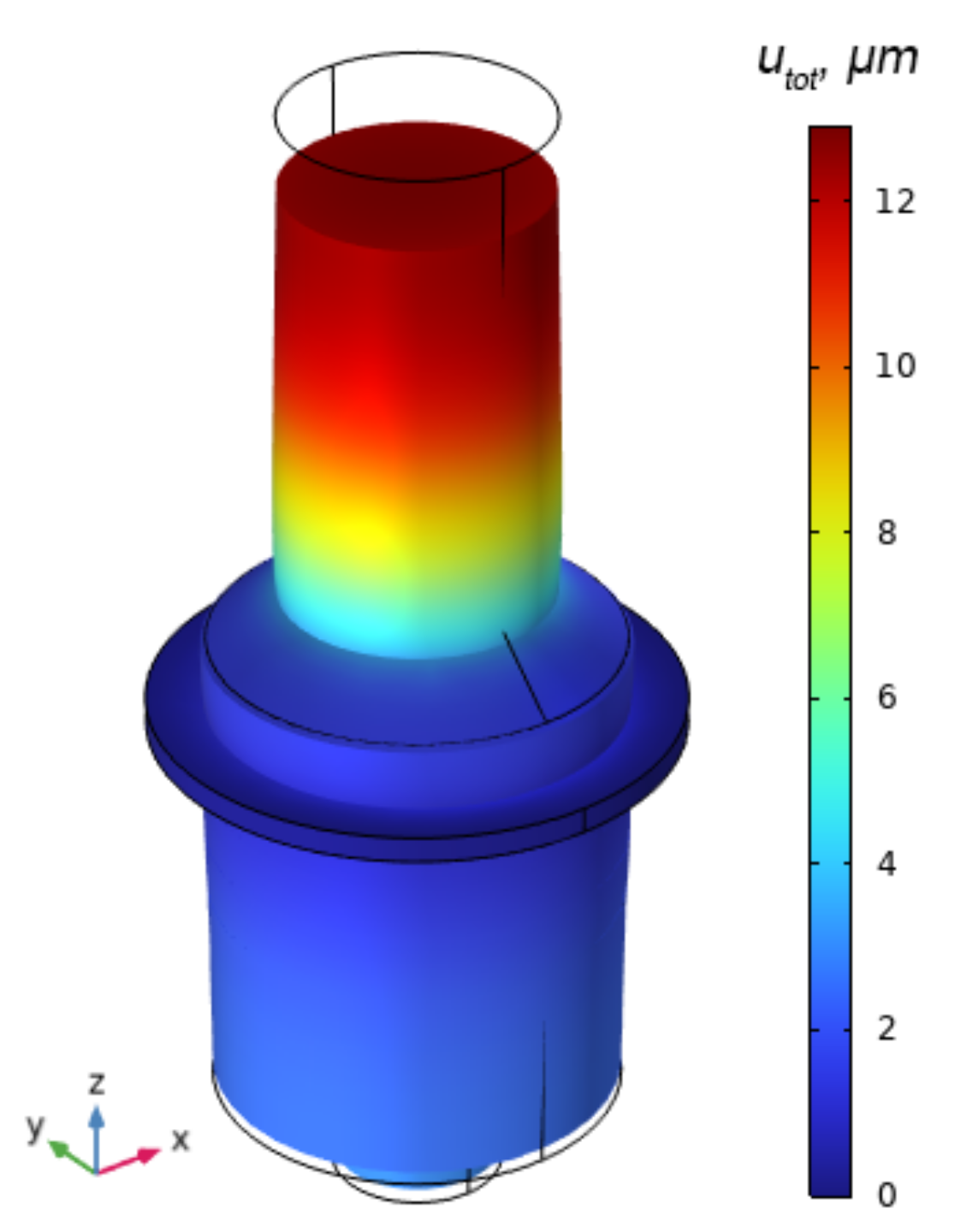
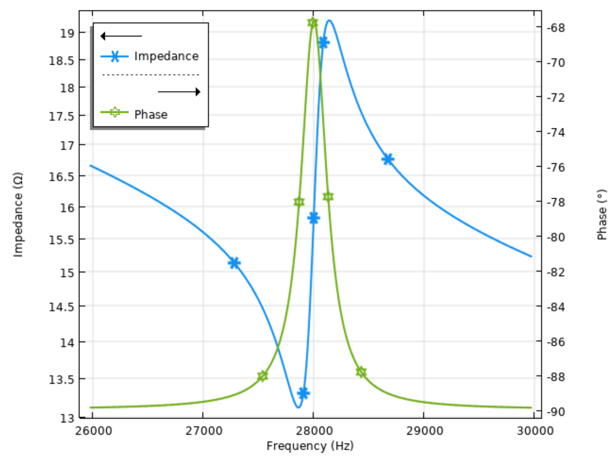
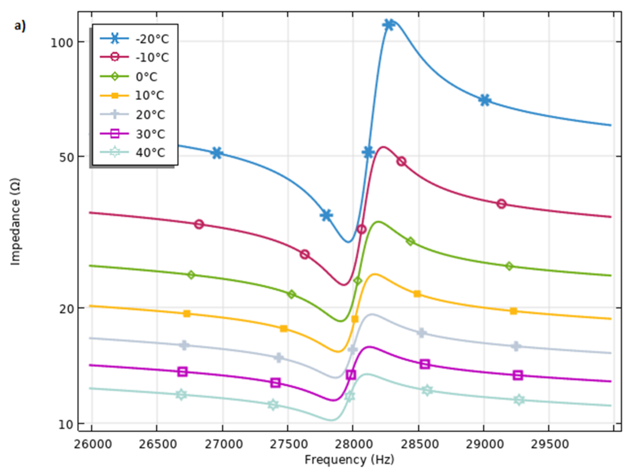
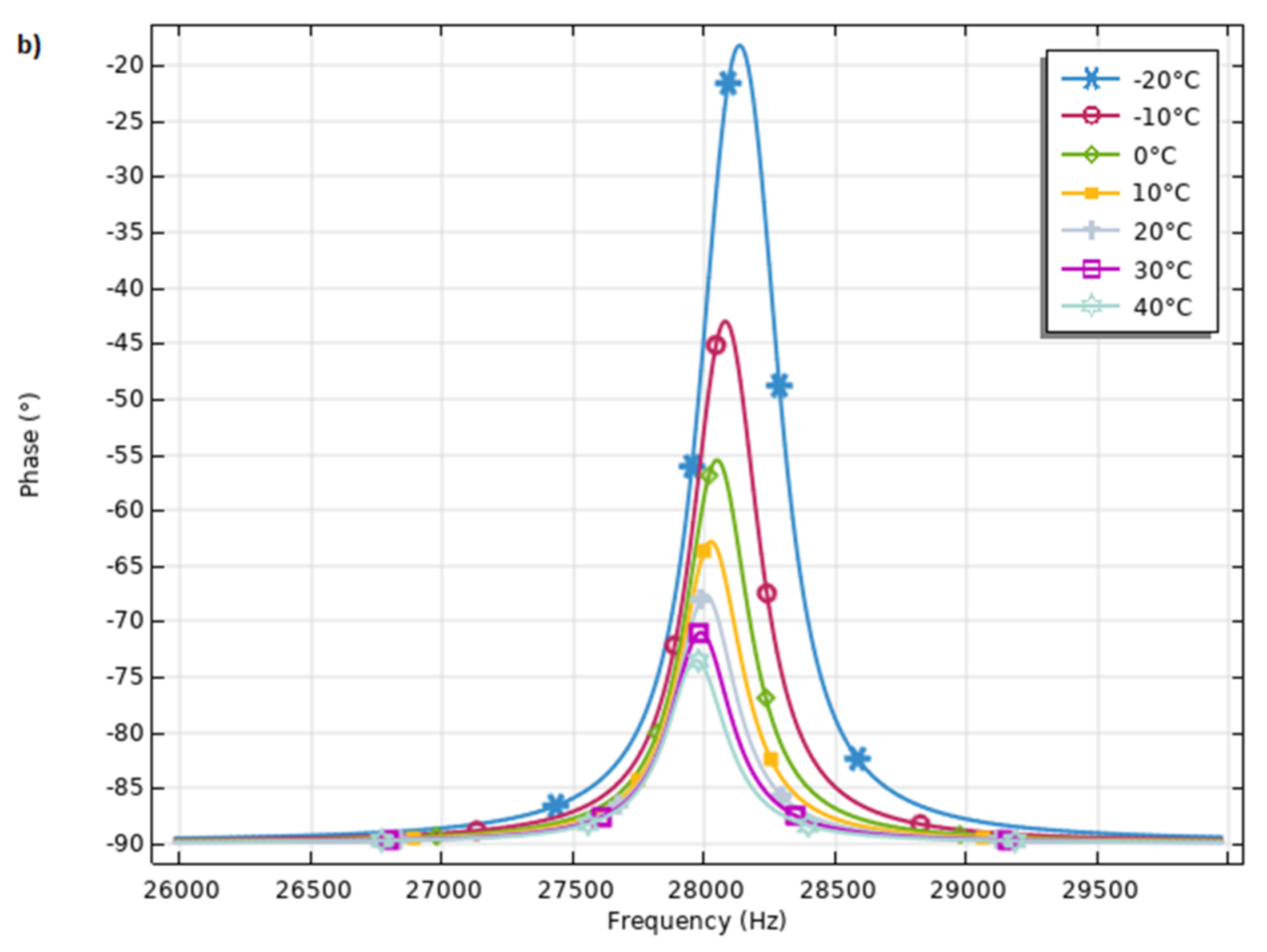
4. Numerical Investigation of Piezoelectric Actuator Under Orbital Conditions

Numerical investigations were performed in order to indicate the influence of the low Earth orbit (LEO) temperature regime and its fluctuations in electromechanical properties of a standard Langevin transducer. A finite element model (FEM) of the transducer as well as orbital environment was built via COMSOL Multiphysics 5.6 software. Mechanical boundary conditions were established as follows: the transducer features a clamping ring structure that was rigidly fixed to replicate a clamped condition, i.e., the ring was set with zero displacements in all degrees of freedom (DOF), ensuring it remains stationary during the simulation. Electrical boundary conditions like neutral and hot electrodes of piezoceramics were included to the model as well.
Finally, the material properties were included in the model (Table 4), i.e., 6063-T83 aluminum characteristics were applied to the horn, DIN 1.4301 steel was used for the pretension bolt and back end of the transducer while Lead Zirconate Titanate (PZT-8) properties were used for the piezoceramic rings; detailed material characteristics are provided in Table 4.
The initial step of the numerical investigations was focused on the modal analysis of the transducer at a temperature of 20 °C. The objective of this analysis was to determine the natural frequency of the first longitudinal vibration mode of the Langevin transducer. The results of the modal analysis are presented in Figure 3. As illustrated, the modal shape of the transducer confirms its operation at the first longitudinal vibration mode and indicates its natural frequency of 27.976 kHz.
The next stage of numerical investigations was dedicated to calculations of the impedance and phase frequency characteristics of the transducer under a temperature of 20 °C. For this purpose, a frequency domain study was conducted over a range from 26 kHz to 30 kHz, with a step size of 5 Hz while boundary conditions were the same as during modal analysis. The results of the calculations are presented in Figure 4.
As can be found in Figure 4, the resonance frequency of the first longitudinal vibration mode was indicated at 27.979 kHz. A slight mismatch of 0.01% between the resonant and natural frequencies was obtained due to the discrete steps used to perform the frequency domain study. Also, the impedance value at the resonance frequency is 13.1 Ω while the effective coupling coefficient (keff) reached a value of 0.0708. Therefore, these results will be used as references during comparison of transducer electromechanical characteristics at temperatures typical for LEO.
Therefore, the next stage of numerical the investigation was conducted to analyze the impedance and phase frequency characteristics of the transducer under LEO temperature conditions. This study included a temperature range from −20 °C to 40 °C with temperature increment steps of 10 °C. For each temperature setting, a frequency domain study was performed over the range of 26 kHz to 30 kHz with a step size of 5 Hz. The results of the calculations are given in Figure 5.
The numerical analysis reveals that the impedance and phase frequency characteristics of the transducer exhibit a temperature-dependent behavior. As observed in the impedance characteristics (Figure 5a), the resonant frequency shifts with changes in temperature. At −20 °C and −10 °C, the resonant frequency is observed to be higher, i.e., 28.3 kHz and 28.01 kHz, respectively. This increase in resonant frequency value can be attributed to the reduced thermal expansion of the actuator materials, resulting in stiffer mechanical properties. Consequently, the resonant frequencies of the transducer increase due to the higher stiffness. As the temperature increases to 30° C and 40 °C, the resonant frequency decreases to 27.96 and 27.95 kHz, respectively. The thermal expansion of the materials at higher temperatures causes a reduction in stiffness, leading to a lower resonance frequency. The impedance peaks become less pronounced, and the phase transitions are less sharp, indicating a lower mechanical response of the transducer. At temperatures around 0 °C to 20 °C, the resonant frequency and the corresponding impedance and phase characteristics show intermediate values. The mechanical properties of the materials are balanced between the effects of thermal contraction and expansion.
As depicted in Figure 5, the impedance characteristics of the transducer exhibit notable variations across the temperature range. At lower temperatures (−20 °C and −10 °C), the impedance shows drops are at a higher level of impedance around the resonance frequency, indicating an increased in electrical and acoustical resistance of the transducer. On the contrary, at higher temperatures (30 °C and 40 °C), the impedance drops are at lower levels, suggesting a decrease in electrical and acoustical resistance.
The phase-frequency characteristics, shown in Figure 5b, further illustrate the effect of temperature on the transducer electro-mechanical characteristics. The phase shift around the resonance frequency of 28.03 kHz is more pronounced at lower temperatures, with a steep phase transition observed at −20 °C. As the temperature increases, the phase transition becomes less sharp, indicating a change in the dynamic response of the actuator. Finally, a summary of the calculated values is given in Table 5.
The resonant frequency decreases with increasing temperature, starting at 28,036 Hz at −20 °C and dropping to 27,946 Hz at 40 °C. Similarly, the impedance at resonance decreases from 29.7316 Ω at −20 °C to 10.1445 Ω at 40 °C. The phase angle also shows a notable shift, from −18.1652° at −20 °C to −73.5094° at 40 °C.
The effective coupling coefficient decreases with increasing temperature, indicating a reduction in the efficiency of energy conversion in the piezoelectric device. The keff values range from 0.9649 at −20 °C to 0.6537 at 40 °C.
These results demonstrate that higher temperatures lead to lower resonant frequencies, impedance, and effective coupling coefficients, impacting the performance of piezoelectric devices in temperature-variable environments. Understanding these dependencies is crucial to optimizing device applications under thermal conditions of the LEO orbit.
Finally, calculations of transducer frequency-displacement characteristics were performed in order to indicate displacements in relation to temperatures. For this purpose, the frequency domain study was set up with the same boundary conditions as in the case before. The results of the calculations are shown in Figure 6.
Figure 6 and Figure 7 illustrate the impact of temperature variations on the displacement amplitudes and resonance frequency of the piezoelectric transducer. The displacement amplitude varies with temperature, and the resonance frequency, where the displacement amplitude peaks, shows a clear trend with changing temperature.
At the lowest temperatures, the resonance frequency and the displacement amplitude are as follows: At −20 °C, the resonance frequency is 28.03 kHz with a displacement amplitude of 3.5295 μm, and at −10 °C, the resonance frequency is 28.01 kHz with a displacement amplitude of 3.53152 μm. At the highest temperatures, the resonance frequency and displacement amplitude are as follows: At 30 °C, the resonance frequency is 27.96 kHz with a displacement amplitude of 3.53761 μm, and at 40 °C, the resonance frequency is 27.95 kHz with a displacement amplitude of 3.53802 μm.
These results indicate that as the temperature increases from −20 °C to 40 °C, the resonance frequency decreases from 28.03 kHz to 27.95 kHz, reflecting a consistent downward trend which was indicated in a previous study and confirmed by calculations of frequency-displacement characteristics. Meanwhile, the displacement amplitude exhibits a slight increase with rising temperature. This temperature-dependent behavior highlights the sensitivity of the resonance frequency to temperature changes, while the displacement amplitude remains relatively stable. Understanding these trends is essential for optimizing the performance and application of piezoelectric devices under varying environmental conditions.
All in all, the conducted numerical investigations underscore the critical impact of temperature on the performance of piezoelectric systems, specifically the Langevin transducer. The impedance and phase frequency characteristics, analyzed across a temperature range from −20 °C to 40 °C, reveal significant variations in the resonant frequency and dynamic response. At lower temperatures, increased stiffness results in higher resonant frequencies and sharper phase transitions, while higher temperatures cause reduced stiffness and lower resonant frequencies. These findings highlight the necessity to take into account thermal effects in the design and optimization of piezoelectric actuators and transducers to ensure consistent and reliable performance under varying operating conditions. The insights provided by this study are highly relevant for the development of temperature-resilient piezoelectric devices.

5. Conclusions

The review comprehensively addresses the significant role and advantages of piezoelectric actuators, motors, and transducers in space applications. These devices, characterized by their ability to convert electrical energy into precise mechanical motion, offer numerous advantages over traditional electromagnetic actuators. Their high precision, responsiveness, compact size, and minimal electromagnetic interference make them exceptionally suitable for the stringent demands of space environments. Moreover, piezoelectric actuators are particularly advantageous in applications requiring fine, accurate movement and positioning, such as the adjustment of optical components in telescopic apparatus, pointing mechanisms, micro-vibration cancelation, and spacecraft orientation control. Their ability to function efficiently across on a wide range of scales, coupled with excellent energy efficiency and high-speed operation, underscores their suitability for various critical tasks in space missions. These advantages of piezoelectric motion systems were proved by their application in missions like the Mars Phoenix Lander, where they facilitated the deployment of scientific instruments, and the Gravity Recovery and Climate Experiment (GRACE) mission, which relied on shear actuators for precise satellite positioning. Furthermore, their utilization in the James Webb Space Telescope for fine steering adjustments and in the HAYABUSA mission for sample collection mechanisms underscores their critical role in advancing space technology.
The analysis of the literature also highlights the challenges posed by the harsh space environment, including vacuum, microgravity, extreme temperatures, and high radiation levels. These conditions require robust design and material considerations to ensure the reliability and longevity of piezoelectric devices.
The numerical investigations presented in this article demonstrate the impact of temperature variations typical of low Earth orbit (LEO) on the electromechanical properties of piezoelectric actuators. The findings reveal significant variations in resonant frequency, impedance, and phase frequency characteristics across a temperature range from −20 °C to 40 °C. For instance, at −20 °C, the resonant frequency was observed to be 28.036 kHz with an impedance of 29.7316 Ω, whereas at 40 °C, the resonant frequency decreased to 27.946 kHz with an impedance of 10.1445 Ω. The phase angle also showed a notable change from −18.1652° at −20 °C to −73.5094° at 40 °C. These results underscore the importance of accounting for thermal effects in the design and optimization of piezoelectric systems to ensure consistent and reliable performance under variable thermal conditions.
Beyond space applications, the unique properties of piezoelectric actuators and motos make them well-suited for use in other harsh environments, such as deep-sea exploration and nuclear facilities. In deep-sea exploration, where precise control and high reliability are critical, piezoelectric actuators and motors could be used to operate submersible vehicle components, manipulate samples, and deploy instruments. Their resistance to electromagnetic interference and ability to function under high pressure and extreme temperatures make them ideal for such applications.
All in all, despite the development of actuators, motors and transducers, structural designs which can withstand space and other harsh environments and ensure, in these environmental conditions, proper and stable operations, future studies should also focus on developing a new piezoelectric material that can better withstand extreme space conditions, advancing miniaturization and integration techniques, and creating adaptive control algorithms for dynamic adjustment to changing space environments. By pursuing these research directions, the full potential of piezoelectric actuators, motors and transducers can be realized, enhancing the capabilities of space missions and contributing to the exploration and understanding of the universe.

Author Contributions

Methodology, L.Š. and A.Č.; formal analysis, L.Š.; investigation, L.Š. and A.Č.; resources, S.B.; data curation, L.Š. and S.B.; writing—original draft preparation, L.Š.; writing—review and editing, A.Č. and S.B.; visualization, L.Š.; supervision, S.B. All authors have read and agreed to the published version of the manuscript.

Funding

This research received no external funding.

Data Availability Statement

Data are contained within the article.

Conflicts of Interest

The authors declare no conflicts of interest.

References

  1. Allegranza, C.; Gaillard, L.; Le Letty, R.; Patti, S.; Scolamiero, L.; Toso, M. Actuators for Space Applications: State of the Art and New Technologies. In Proceedings of the 14th International Conference on New Actuators, Bremen, Germany, 23–25 June 2014. [Google Scholar]
  2. Prasad, B.B.; Biju, N.; Panicker, M.R.R.; Kumar, K.; Murugesan, V. Failure Mode Investigation and Redundancy Management of an Electromechanical Control Actuator for Launch Vehicle Application. J. Fail. Anal. Prev. 2020, 20, 1644–1660. [Google Scholar] [CrossRef]
  3. Sivaprakash, N.; Shanmugam, J. Neural Network Based Three Axis Satellite Attitude Control Using Only Magnetic Torquers. J. Aerosp. Sci. Technol. 2023, 58, 71–77. [Google Scholar] [CrossRef]
  4. Feldmann, M.; Waldschik, A. Electromagnetic micro-actuators, micro-motors, and micro-robots. In Microelectronics: Design, Technology, and Packaging III; SPIE: Bellingham, WA, USA, 2007; Volume 6798, pp. 252–261. [Google Scholar] [CrossRef]
  5. Su, X.; Jia, Y.; Han, C.; Hu, Y.; Fu, Z.; Liu, K.; Yu, Y.; Yan, X.; Wang, Y. Flash sintering of lead zirconate titanate ceramics under an alternating current electrical field. Ceram. Int. 2019, 45, 5168–5173. [Google Scholar] [CrossRef]
  6. Naik, R.; Mohit, S.; Chavan, S. Piezoelectric property investigation on PVDF/ZrO2/ZnO nanocomposite for energy harvesting application. Eng. Res. Express 2021, 3, 025003. [Google Scholar] [CrossRef]
  7. Koc, B.; Uchino, K.; Motors, P.U. Piezoelectric Ultrasonic Motors. In Reference Module in Materials Science and Materials Engineering; Elsevier: Amsterdam, The Netherlands, 2016. [Google Scholar] [CrossRef]
  8. Priya, S.; Inman, D.J. Energy Harvesting Technologies; Springer: New York, NY, USA, 2009. [Google Scholar] [CrossRef]
  9. Mohith, S.; Upadhya, A.R.; Navin, K.P.; Kulkarni, S.M.; Rao, M. Recent trends in piezoelectric actuators for precision motion and their applications: A review. Smart Mater. Struct. 2021, 30, 013002. [Google Scholar] [CrossRef]
  10. Newnham, R.E. Properties of Materials: Anisotropy, Symmetry, Structure; Oxford University Press: Oxford, UK, 2005; Volume 42. [Google Scholar] [CrossRef]
  11. Gao, X.; Yang, J.; Wu, J.; Xin, X.; Li, Z.; Yuan, X.; Shen, X.; Dong, S. Piezoelectric Actuators and Motors: Materials, Designs, and Applications. Adv. Mater. Technol. 2020, 5, 1900716. [Google Scholar] [CrossRef]
  12. Niezrecki, C.; Brei, D.; Balakrishnan, S.; Moskalik, A. Piezoelectric actuation: State of the art. Shock Vib. Dig. 2001, 33, 269–280. [Google Scholar] [CrossRef]
  13. Mo, C.; Wright, R.; Slaughter, W.S.; Clark, W.W. Behaviour of a unimorph circular piezoelectric actuator. Smart Mater. Struct. 2006, 15, 1094–1102. [Google Scholar] [CrossRef]
  14. Chi, Z.; Xu, Q. Recent advances in the control of piezoelectric actuators. Int. J. Adv. Robot. Syst. 2014, 11, 182. [Google Scholar] [CrossRef]
  15. Aldraihem, O.J.; Singh, T.; Wetherhold, R.C. Optimal Size and Location of Piezoelectric Actuator/Sensors: Practical Considerations. J. Guid. Control Dyn. 2000, 23, 509–515. [Google Scholar] [CrossRef]
  16. Le Letty, R.; Barillot, F.; Fabbro, H.; Guay, P.; Cadiergues, L. Piezoelectric actuators for active optics. In Proceedings of the International Conference on Space Optics—ICSO 2004, Toulouse, France, 30 March–2 April 2004. [Google Scholar] [CrossRef]
  17. Jono, T.; Takayama, Y.; Ohinata, K.; Kura, N.; Koyama, Y.; Arai, K.; Shiratama, K.; Sodnik, Z.; Bird, A.; Demelenne, B. Demonstrations of ARTEMIS-OICETS inter-satellite laser communications. In Proceedings of the Collection of Technical Papers—24th AIAA International Communications Satellite Systems Conference, ICSSC, San Diego, CA, USA, 11–14 June 2006. [Google Scholar] [CrossRef]
  18. Wei, Z.; Li, D.; Luo, Q.; Jiang, J. Modeling and analysis of a flywheel microvibration isolation system for spacecrafts. Adv. Space Res. 2015, 55, 761–777. [Google Scholar] [CrossRef]
  19. Pages, A.; Maillard, T.; Rebufa, J. Piezo actuators for telescope active optics. In Proceedings of the Advances in Optical and Mechanical Technologies for Telescopes and Instrumentation V, Montreal, QC, Canada, 17–22 July 2022. [Google Scholar] [CrossRef]
  20. Freudling, M.; Grzesik, A.; Erhard, M.; Gerhards, M.; Leitz, S.; Verpoort, S.; Wittrock, U.; Hallibert, P. Space-qualified Piezo Based Deformable Mirror for future Instruments with Active Optics. In Proceedings of the International Conference on Space Optics—ICSO 2020, Online, 30 March–2 April 2021. [Google Scholar] [CrossRef]
  21. Nagarajaiah, N.K.D.; Neri, G.; Chaliyath, A.J.; Chiarelli, M.R.; Di Rito, G. Use of piezoelectric actuators for thrust vectoring in ion engines: Conceptual design and preliminary analysis. In Proceedings of the 2020 IEEE International Workshop on Metrology for AeroSpace, MetroAeroSpace 2020—Proceedings, Pisa, Italy, 22–24 June 2020. [Google Scholar] [CrossRef]
  22. Delpero, T.; Bergamini, A.; Ermanni, P. Concurrent Design of Adaptively Damped Structures. In Proceedings of the ICAST 2014, Ota, Nigeria, 29–31 October 2014. [Google Scholar]
  23. Lu, Y.; Shao, Q.; Yue, H.; Yang, F. A Review of the Space Environment Effects on Spacecraft in Different Orbits. IEEE Access 2019, 7, 93473–93488. [Google Scholar] [CrossRef]
  24. Messenger, G.C.; Ash, M.S. The Effects of Radiation on Electronic Systems; Springer: Dordrecht, The Netherlands, 1986. [Google Scholar] [CrossRef]
  25. Rycroft, M.J. The Space environment: Implications for spacecraft design. J. Atmos. Terr. Phys. 1996, 58, 1815–1816. [Google Scholar] [CrossRef]
  26. Velazco, R.; Fouillat, P.; Reis, R. Radiation Effects on Embedded Systems; Springer: Dordrecht, The Netherlands, 2007. [Google Scholar] [CrossRef]
  27. Xu, T.B.; Huffine, J. Review on PMN-PT Relaxor Piezoelectric Single Crystal Materials for Cryogenic Actuators. In Proceedings of the AIAA Science and Technology Forum and Exposition, AIAA SciTech Forum 2022, San Diego, CA, USA, 3–7 January 2022. [Google Scholar] [CrossRef]
  28. Liu, H.L. Variability and predictability of the space environment as related to lower atmosphere forcing. Space Weather 2016, 14, 634–658. [Google Scholar] [CrossRef]
  29. Gombosi, T.I.; Holman, G.D. Physics of the Space Environment. Phys. Today 1999, 52, 62–63. [Google Scholar] [CrossRef]
  30. Koons, H.C.; Mazur, J.E.; Selesnick, R.S.; Blake, J.B.; Fennell, J.F.; Roeder, J.L.; Anderson, P.C. The impact of the space environment on space systems. In Proceedings of the 6th Spacecraft Charging Technology Conference, AFRL Science Center, Hanscom AFB, MA, USA, 1 September 2000. [Google Scholar]
  31. Prölss, G.W. Physics of the Earth’s Space Environment; Springer: Dordrecht, The Netherlands, 2004. [Google Scholar] [CrossRef]
  32. Bourdarie, S.; Xapsos, M. The near-Earth space radiation environment. IEEE Trans. Nucl. Sci. 2008, 55, 1810–1832. [Google Scholar] [CrossRef]
  33. Vayner, B.V.; Ferguson, D.C.; Galofaro, J.T. Comparative analysis of arcing in leo and geo simulated environments. In Proceedings of the Collection of Technical Papers—45th AIAA Aerospace Sciences Meeting, Reno, NV, USA, 8–11 January 2007. [Google Scholar] [CrossRef]
  34. Kiefer, J.; Pross, H. Space radiation effects and microgravity. Mutat. Res. Mol. Mech. Mutagen. 1999, 430, 299–305. [Google Scholar] [CrossRef]
  35. Snell, E.H.; Helliwell, J.R. Microgravity as an environment for macromolecular crystallization—An outlook in the era of space stations and commercial space flight. Crystallogr. Rev. 2021, 27, 3–46. [Google Scholar] [CrossRef]
  36. Anderson, M.; Zagrai, A.N.; Daniel, J.D.; Westpfahl, D.J.; Henneke, D. Investigating effect of space radiation environment on piezoelectric sensors: Cobalt-60 irradiation experiment. J. Nondestruct. Eval. Diagn. Progn. Eng. Syst. 2017, 1, 011007. [Google Scholar] [CrossRef]
  37. Gorney, D.J. Solar cycle effects on the near-Earth space environment. Rev. Geophys. 1990, 28, 315–336. [Google Scholar] [CrossRef]
  38. Kim, M.Y.; Wilson, J.W.; Cucinotta, F.A. A solar cycle statistical model for the projection of space radiation environment. Adv. Space Res. 2005, 37, 1741–1748. [Google Scholar] [CrossRef]
  39. Dyer, C. Radiation effects on spacecraft & aircraft. In Proceedings of the Solspa 2001, The Second Solar Cycle and Space Weather Euroconference, Vico Equense, Italy, 24–29 September 2002. [Google Scholar]
  40. Sharma, A.K.; Sridhara, N. Degradation of thermal control materials under a simulated radiative space environment. Adv. Space Res. 2012, 50, 1411–1424. [Google Scholar] [CrossRef]
  41. Lachance, J.; Coa, C.; Fozza, A.C.; Czeremuszkin, G.; Houdayer, A.; Wertheimer, M.R. Radiation-induced degradation of polymeric spacecraft materials under protective oxide coatings. Nucl. Instrum. Methods Phys. Res. B 2001, 185, 328–335. [Google Scholar] [CrossRef]
  42. Patrick, T. Space environment and vacuum properties of spacecraft materials. Vacuum 1981, 31, 351–357. [Google Scholar] [CrossRef]
  43. Anwar, A.; Albano, M.; Hassan, G.; Delfini, A.; Volpini, F.; Marchetti, M.; Elfiky, D. Vacuum Effect on Spacecraft Structure Materials. Int. Conf. Aerosp. Sci. Aviat. Technol. 2015, 16, 1–10. [Google Scholar] [CrossRef]
  44. Fayazbakhsh, K.; Abedian, A. Materials selection for applications in space environment considering outgassing phenomenon. Adv. Space Res. 2010, 45, 741–749. [Google Scholar] [CrossRef]
  45. Urayama, F.; Hayashi, T.; Takeda, N.; Baba, N. Modeling of material outgassing and deposition phenomena. In Proceedings of the Optical Systems Degradation, Contamination, and Stray Light: Effects, Measurements, and Control, Denver, CO, USA, 2–5 August 2004. [Google Scholar] [CrossRef]
  46. Anderson, J.R.; Wong, A.T.; Fugett, D.; Hoey, W. Modeling Radiation Influence on Spacecraft Materials Outgassing. In Proceedings of the IEEE Aerospace Conference Proceedings, Big Sky, MT, USA, 7–14 March 2020. [Google Scholar] [CrossRef]
  47. Novikov, L.; Chernik, V.N.; Naumov, S.F.; Sokolova, S.P.; Gerasimova, T.I.; Kurilyonok, A.O.; Smirnova, T.N. Degradation Testing of Spacecraft Materials for Long Flights in Low Earth Orbit. J. Spacecr. Rocket. 2006, 43, 534–538. [Google Scholar] [CrossRef]
  48. Miller, S.K.; Banks, B. Degradation of Spacecraft Materials in the Space Environment. MRS Bull. 2010, 35, 20–24. [Google Scholar] [CrossRef]
  49. Roberts, E.W. Space tribology: Its role in spacecraft mechanisms. J. Phys. D Appl. Phys. 2012, 45, 503001. [Google Scholar] [CrossRef]
  50. Walter, N.A.; Scialdone, J.J. Outgassing Data for Selecting Spacecraft Materials; NASA: Greenbelt, MA, USA, 1997; Revision 4. [Google Scholar]
  51. Grossman, E.; Gouzman, I. Space environment effects on polymers in low earth orbit. Nucl. Instruments Methods Phys. Res. Sect. B Beam Interact. Mater. At. 2003, 208, 48–57. [Google Scholar] [CrossRef]
  52. Hunstig, M. Piezoelectric Inertia Motors—A Critical Review of History, Concepts, Design, Applications, and Perspectives. Actuators 2017, 6, 7. [Google Scholar] [CrossRef]
  53. Zhou, X.; Wu, S.; Wang, X.; Wang, Z.; Zhu, Q.; Sun, J.; Huang, P.; Wang, X.; Huang, W.; Lu, Q. Review on piezoelectric actuators: Materials, classifications, applications, and recent trends. Front. Mech. Eng. 2024, 19, 6. [Google Scholar] [CrossRef]
  54. Deng, J.; Cheng, J.; Guan, Y.; Li, H.; Lu, F.; Chen, W. Research on the Influence of Friction Pairs on the Output Characteristics of the Piezoelectric Ultrasonic Actuator. Actuators 2022, 11, 212. [Google Scholar] [CrossRef]
  55. Gadalla, M.A. Prediction of temperature variation in a rotating spacecraft in space environment. Appl. Therm. Eng. 2005, 25, 2379–2397. [Google Scholar] [CrossRef]
  56. Tan, Q.; Li, F.; Liu, L.; Liu, Y.; Leng, J. Effects of vacuum thermal cycling, ultraviolet radiation and atomic oxygen on the mechanical properties of carbon fiber/epoxy shape memory polymer composite. Polym. Test. 2023, 118, 107915. [Google Scholar] [CrossRef]
  57. Meseguer, J.; Pérez-Grande, I.; Sanz-Andrés, A. Spacecraft Thermal Control; Elsevier: Amsterdam, The Netherlands, 2012. [Google Scholar] [CrossRef]
  58. Hengeveld, D.W.; Mathison, M.M.; Braun, J.E.; Groll, E.A.; Williams, A.D. Review of modern spacecraft thermal control technologies. HVAC&R Res. 2010, 16, 189–220. [Google Scholar] [CrossRef]
  59. Tachikawa, S.; Nagano, H.; Ohnishi, A.; Nagasaka, Y. Advanced Passive Thermal Control Materials and Devices for Spacecraft: A Review. Int. J. Thermophys. 2022, 43, 91. [Google Scholar] [CrossRef]
  60. Mermer, E.; Ünal, R. Passive thermal control systems in spacecrafts. J. Braz. Soc. Mech. Sci. Eng. 2023, 45, 160. [Google Scholar] [CrossRef]
  61. Hengeveld, D.W.; Braun, J.E.; Williams, A.D. Review of Modern Spacecraft Thermal Control Technologies and Their Application to Next- Generation Buildings. In Proceedings of the International High Performance Buildings Conference, Purdue, IN, USA, 12–15 July 2010. [Google Scholar]
  62. Osiander, R.; Firebaugh, S.; Champion, J.; Farrar, D.; GarrisonDarrin, M. Microelectromechanical Devices for Satellite Thermal Control. IEEE Sens. J. 2004, 4, 525–531. [Google Scholar] [CrossRef]
  63. Huang, J.; Chang, L.; Dong, B.; Liu, Z.; Han, S.; Si, C. Development on Space Environment and Its Dynamic and Thermal Problems of Ultra-LEO Satellites. Chin. J. Space Sci. 2023, 43, 711–713. [Google Scholar] [CrossRef]
  64. Sadkin, Y. Spacecraft quasi-static test performed on a shaker. In Proceedings of the 5th International Symposium on Environmental Testing for Space Programmes, Noordwijk, The Netherlands, 15–17 June 2004. [Google Scholar]
  65. Kamesh, D.; Pandiyan, R.; Ghosal, A. Modeling, design and analysis of low frequency platform for attenuating micro-vibration in spacecraft. J. Sound Vib. 2010, 329, 3431–3450. [Google Scholar] [CrossRef]
  66. Xu, Z.-D.; Chen, Z.-H.; Huang, X.-H.; Zhou, C.-Y.; Hu, Z.-W.; Yang, Q.-H.; Gai, P.-P. Recent advances in multi-dimensional vibration mitigation materials and devices. Front. Mater. 2019, 6, 143. [Google Scholar] [CrossRef]
  67. Han, Q.; Gao, S.; Chu, F. Micro-Vibration Analysis, Suppression, and Isolation of Spacecraft Flywheel Rotor Systems: A Review. Vibration 2024, 7, 229–263. [Google Scholar] [CrossRef]
  68. Claeyssen, F.; Le Letty, R.; Barillot, F.; Sosnicki, O. Amplified Piezoelectric Actuators: Static & Dynamic Applications. Ferroelectrics 2007, 351, 3–14. [Google Scholar] [CrossRef]
  69. Metz, B. Optimizing 3-component force sensor installation for satellite force limited vibration testing. In Proceedings of the 28th Space Simulation Conference—Extreme Environments: Pushing the Boundaries, Baltimore, MY, USA, 3–6 November 2014. [Google Scholar]
  70. JSC. “NanoAvionics”. NanoAvionics CubeSat Reaction Wheels RW0. Available online: https://nanoavionics.com/ (accessed on 8 August 2024).
  71. JSC. “AAC CLYDE SPACE”. AAC Clyde Space Reaction wheel RW400. Available online: https://www.aac-clyde.space (accessed on 8 August 2024).
  72. Yoshikawa, M.; Kawaguchi, J.; Fujiwara, A.; Tsuchiyama, A. The Hayabusa mission. In Sample Return Missions: The Last Frontier of Solar System Exploration; Elsevier: Amsterdam, The Netherlands, 2021. [Google Scholar] [CrossRef]
  73. Li, C.; Liu, J.; Ren, X.; Zuo, W.; Tan, X.; Wen, W.; Li, H.; Mu, L.; Su, Y.; Zhang, H.; et al. The Chang’e 3 Mission Overview. Space Sci. Rev. 2015, 190, 85–101. [Google Scholar] [CrossRef]
  74. Haq, M. Application of piezo transducers in biomedical science for health monitoring and energy harvesting problems. Mater. Res. Express 2019, 6, 022002. [Google Scholar] [CrossRef]
  75. Sherrit, S.; Jones, C.M.; Aldrich, J.B.; Blodget, C.; Bao, X.; Badescu, M.; Bar-Cohen, Y. Multilayer piezoelectric stack actuator characterization. In Proceedings of the Behavior and Mechanics of Multifunctional and Composite Materials 2008, San Diego, CA, USA, 10–13 March 2008. [Google Scholar] [CrossRef]
  76. Zhu, W.; Chen, G.; Rui, X. Modeling of piezoelectric stack actuators considering bonding layers. J. Intell. Mater. Syst. Struct. 2015, 26, 2418–2427. [Google Scholar] [CrossRef]
  77. Parrat, D.; Gautsch, S.; Howald, L.; Brändlin-Müller, D.; De Rooij, N.F.; Staufer, U. Design and evaluation of a polyimide spring system for the scanning force microscope of the phoenix mars mission 2007. In Proceedings of the 11th European Space Mechanisms and Tribology Symposium, ESMATS 2005, Lucerne, Switzerland, 21–23 September 2005. [Google Scholar]
  78. Maillard, T.; Le Letty, R.; Barillot, F.; Rajeev, G. Piezo Mechanisms for Optical and Space Applications in Europe. J. Aerosp. Sci. Technol. 2023, 19, 142–147. [Google Scholar] [CrossRef]
  79. Ma, L.; Wu, L.-Z.; Zhou, Z.-G.; Guo, L.-C. Fracture analysis of a functionally graded piezoelectric strip. Compos. Struct. 2005, 69, 294–300. [Google Scholar] [CrossRef]
  80. Chen, J.; Li, X.; Liu, G.; Chen, Z.; Dong, S. A shear-bending mode high temperature piezoelectric actuator. Appl. Phys. Lett. 2012, 101, 012909. [Google Scholar] [CrossRef]
  81. Tapley, B.D.; Bettadpur, S.; Watkins, M.; Reigber, C. The gravity recovery and climate experiment: Mission overview and early results. Geophys. Res. Lett. 2004, 31, L09607. [Google Scholar] [CrossRef]
  82. Touboul, P.; Foulon, B.; Christophe, B.; Marque, J.P. CHAMP, GRACE, GOCE instruments and beyond. In Proceedings of the International Association of Geodesy Symposia, Venice, Italy, 9–12 October 2012. [Google Scholar] [CrossRef]
  83. Sheard, B.S.; Heinzel, G.; Danzmann, K.; Shaddock, D.A.; Klipstein, W.M.; Folkner, W.M. Intersatellite laser ranging instrument for the GRACE follow-on mission. J. Geodesy 2012, 86, 1083–1095. [Google Scholar] [CrossRef]
  84. Taya, M.; Almajid, A.A.; Dunn, M.; Takahashi, H. Design of bimorph piezo-composite actuators with functionally graded microstructure. Sens. Actuators A Phys. 2003, 107, 248–260. [Google Scholar] [CrossRef]
  85. Chattaraj, N.; Ganguli, R. Performance improvement of a piezoelectric bimorph actuator by tailoring geometry. Mech. Adv. Mater. Struct. 2017, 25, 829–835. [Google Scholar] [CrossRef]
  86. Greenhouse, M.A. The JWST science instrument payload: Mission context and status. In Proceedings of the Space Telescopes and Instrumentation 2016: Optical, Infrared, and Millimeter Wave, Edinburgh, UK, 26 June–1 July 2016. [Google Scholar] [CrossRef]
  87. Birkmann, S.M.; Ferruit, P.; Rawle, T.; Sirianni, M.; de Oliveira, C.A.; Böker, T.; Giardino, G.; Lützgendorf, N.; Marston, A.; Stuhlinger, M.; et al. The JWST/NIRSpec instrument: Update on status and performances. In Proceedings of the Space Telescopes and Instrumentation 2016: Optical, Infrared, and Millimeter Wave, Edinburgh, UK, 26 June–1 July 2016. [Google Scholar] [CrossRef]
  88. Wright, G.S.; Rieke, G.H.; Colina, L.; van Dishoeck, E.; Goodson, G.; Greene, T.; Lagage, P.-O.; Karnik, A.; Lambros, S.D.; Lemke, D.; et al. The JWST MIRI instrument concept. In Proceedings of the Optical, Infrared, and Millimeter Space Telescopes, Glasgow, UK, 21–25 June 2004. [Google Scholar] [CrossRef]
  89. Uchino, K. Piezoelectric ultrasonic motors: Overview. Smart Mater. Struct. 1998, 7, 273–285. [Google Scholar] [CrossRef]
  90. Li, X.; Wen, Z.; Jia, B.; Cao, T.; Yu, D.; Wu, D. A Review of Application and Development Trends in Ultrasonic Motors. ES Mater. Manuf. 2021, 12, 3–16. [Google Scholar] [CrossRef]
  91. Bekiroglu, E. Ultrasonic motors: Their models, drives, controls and applications. J. Electroceramics 2007, 20, 277–286. [Google Scholar] [CrossRef]
  92. Jingzhuo, S.; Dongmei, Y. Characteristic model of travelling wave ultrasonic motor. Ultrasonics 2014, 54, 725–730. [Google Scholar] [CrossRef]
  93. Ryndzionek, R.; Sienkiewicz, Ł. A review of recent advances in the single- and multi-degree-of-freedom ultrasonic piezoelectric motors. Ultrasonics 2021, 116, 106471. [Google Scholar] [CrossRef]
  94. Riu, L.; Bibring, J.-P.; Pilorget, C.; Poulet, F.; Hamm, V. The on-ground calibration performances of the hyperspectral microscope MicrOmega for the Hayabusa-2 mission. Planet. Space Sci. 2018, 152, 31–44. [Google Scholar] [CrossRef]
  95. Radi, B.; El Hami, A. The study of the dynamic contact in ultrasonic motor. Appl. Math. Model. 2010, 34, 3767–3777. [Google Scholar] [CrossRef]
  96. Zhou, H.; Feng, X.; Dong, Z.; Liu, C.; Liang, W. Application of Denoising CNN for Noise Suppression and Weak Signal Extraction of Lunar Penetrating Radar Data. Remote. Sens. 2021, 13, 779. [Google Scholar] [CrossRef]
  97. Li, C.L.; Xu, R.; Lv, G.; Yuan, L.Y.; He, Z.P.; Wang, J.Y. Detection and calibration characteristics of the visible and near-infrared imaging spectrometer in the Chang’e-4. Rev. Sci. Instrum. 2019, 90, 103106. [Google Scholar] [CrossRef]
  98. Delaboudinière, J.P.; Artzner, G.E.; Brunaud, J.; Gabriel, A.H.; Hochedez, J.F.; Millier, F.; Song, X.Y.; Au, B.; Dere, K.P.; Howard, R.A.; et al. EIT: Extreme-ultraviolet Imaging Telescope for the SOHO mission. Sol. Phys. 1995, 162, 291–312. [Google Scholar] [CrossRef]
  99. Meng, Y.; Chen, G.; Huang, M. Piezoelectric Materials: Properties, Advancements, and Design Strategies for High-Temperature Applications. Nanomaterials 2022, 12, 1171. [Google Scholar] [CrossRef]
  100. Jin, H.; Gao, X.; Ren, K.; Liu, J.; Qiao, L.; Liu, M.; Chen, W.; He, Y.; Dong, S.; Xu, Z.; et al. Review on Piezoelectric Actuators Based on High-Performance Piezoelectric Materials. IEEE Trans. Ultrason. Ferroelectr. Freq. Control 2022, 69, 3057–3069. [Google Scholar] [CrossRef]
  101. ShSharma, Y.; Lee, M.-C.; Pitike, K.C.; Mishra, K.K.; Zheng, Q.; Gao, X.; Musico, B.L.; Mazza, A.R.; Katiyar, R.S.; Keppens, V.; et al. High Entropy Oxide Relaxor Ferroelectrics. ACS Appl. Mater. Interfaces 2022, 14, 11962–11970. [Google Scholar] [CrossRef]
  102. Jayakrishnan, A.; Silva, J.; Kamakshi, K.; Dastan, D.; Annapureddy, V.; Pereira, M.; Sekhar, K. Are lead-free relaxor ferroelectric materials the most promising candidates for energy storage capacitors? Prog. Mater. Sci. 2023, 132, 101046. [Google Scholar] [CrossRef]
Figure 1. Example of sliding friction coefficient dependence on vacuum.
Actuators 13 00312 g001
Figure 2. Thermal cycle at low Earth orbit (LEO).
Actuators 13 00312 g002
Figure 3. The modal shape of the transducer at 27.976 kHz.
Actuators 13 00312 g003
Figure 4. Impedance and phase-frequency characteristics of the transducer at 20 °C.
Actuators 13 00312 g004
Figure 5. Impedance and phase frequency characteristics of the transducer under different temperature conditions; (a) impedance-frequency characteristics of the transducer; (b) phase-frequency characteristics of the transducer.
Actuators 13 00312 g005aActuators 13 00312 g005b
Figure 6. The frequency-displacement characteristics of the transducer at different temperatures while the excitation signal was 100 Vp-p: (a) a full view of the characteristics; (b) a detailed view of the characteristic peaks.
Actuators 13 00312 g006
Figure 7. Summary of the maximum displacement amplitudes at different temperatures while the excitation signal amplitude was 100 Vp-p.
Actuators 13 00312 g007
Table 2. Comparison between electromagnetic and piezoelectric motors [70,71,72,73].
Type of MotorType of Motion SourceDynamic and Physical Characteristics
NanoAvionics CubeSat Reaction Wheels RW0 DC brushless motorMass—137 g
Maximum speed—6500 RPM
Maximum torque—3.2 mNm
Power consumption—0.15 W @ 1000 RPM
Volume—45.41 cm3
AAC Clyde Space Reaction wheel RW400DC brushless motorMass—197 g
Maximum speed—5000 RPM
Maximum torque—8 mNm
Power consumption—1.9 W peak
Volume—67.5 cm3
Piezoelectric motor used in HAYABUSA (MUSES−C) space mission for sample collection from asteroidUltrasonic motorMass—150—200 g
Maximum speed—1000 RPM
Maximum torque—in range from 0.1 to 1 Nm
Power consumption—in range from 5 to 20 W
Volume—55.2 cm3
Piezoelectric motor used in Chang’e−3 (Yutu rover) space mission for soil sampling and instrument positioning Ultrasonic motorMass—250 g
Maximum speed—1200 RPM
Maximum torque—in range from 0.2 to 1.2 Nm
Power consumption—in range from 8 to 15 W
Volume—64.1 cm3
Table 3. Summary of piezoelectric actuators used in real-life space missions [72,73,75,83,88,94].
Type of Piezoelectric ActuatorTitle of Space Mission Mission ObjectiveInstrument Utilizing Piezo DevicePiezoelectric Actuator Specifications
Multilayer Mars Phoenix LanderSoil and atmospheric analysis on MarsSatellite antenna deploymentHigh force, precise displacement, compact and robust structure, high force-to-weight ratio, excellent frequency response, minimal electromagnetic interference.
Shear-TypeGRACE (Gravity Recovery and Climate Experiment)Detailed measurements of Earth’s gravitational fieldFine adjustment of the relative positions of onboard instrumentsPrecise, multidirectional positioning, compensating for thermal expansions and contractions, maintaining precise alignment.
BimorphJames Webb Space Telescope (JWST)High-resolution imaging of distant celestial objectsFine steering mirrorGreater displacement and sensitivity, low power consumption, minimal mechanical complexity, high precision, redundant dual-layer construction for enhanced reliability.
Ultrasonic MotorHAYABUSA (MUSES-C)Sample collection from asteroidDeployment mechanisms of sample collection deviceRotary–type motors, compact design 35–40 mm in diameter, 40–50 mm in height, weight in range of 150–200 g, torque output in range of 0.1–1 Nm, angular speed up to 1000 RPM, operational voltage in range of 24–48V, power consumption in range of 5–20 W.
Ultrasonic MotorChang’e–3 (Yutu rover)Soil sampling and instrument positioning on the MoonRobotic armCompact, 50 mm diameter, 60 mm length, weight 250 g, torque 0.2–1.2 Nm, angular speed up to 1200 RPM, operational voltage 28–40), power consumption 8–15 W.
Ultrasonic MotorSOHO (Solar and Heliospheric Observatory)Study the Sun, from its deep core to the outer corona, and solar windPrecise adjustments of instruments for solar observationLinear movement, compact 35 mm length, 10 mm diameter, operational speed up to 200 mm/s, low power consumption 2–10 W, high resolution and stability.
Table 4. Material characteristics.
Material PropertiesStainless Steel DIN 1.4301Lead Zirconate Titanate (PZT-8)Aluminum 6063-T83
Density, [kg/m3]800076003980
Young’s modulus, [N/m2]193∙10911∙10106.9∙1010
Poisson’s coefficient 0.290.310.33
Isotropic structural loss factor0.020.4∙10−3
Relative permittivityε11T0 = 1290
ε22T0 = 1290
ε33T0 = 1000
Elastic compliance coefficient, [10−12 m2/N]S11E = 11.50
S33E = 13.50
Elastic stiffness coefficient c33D, [N/m2]14.6·1010
Piezoelectric constant d33, [10−12 m/V]225
Piezoelectric constant d31, [10−12 m/V]−97
Piezoelectric constant d15, [10−12 m/V]330
Coefficient of thermal expansion, [1/K]12.3∙10−65∙10−623.4∙10−6
Thermal conductivity, [W/(m·K)]44.51.2201
Table 5. Summary of calculated electromechanical values at different temperatures.
Temperature [°C]Resonant Frequency [Hz]Impedance
[Ω]
Phase [°]keff
−2028,036297,316−181,6520.0708
−1028,016229,522−429,9850.0803
028,006184,398−554,8040.0860
1027,98615,343−628,3450.0848
2027,976131,134−676,3920.0889
3027,966114,413−710,0880.0929
4027,946101,445−73,50940.0890
Disclaimer/Publisher’s Note: The statements, opinions and data contained in all publications are solely those of the individual author(s) and contributor(s) and not of MDPI and/or the editor(s). MDPI and/or the editor(s) disclaim responsibility for any injury to people or property resulting from any ideas, methods, instructions or products referred to in the content.

