
Addressing EMI and EMF Challenges in EV Wireless Charging with the Alternating Voltage Phase Coil


Abstract
:1. Introduction
- Primary objective: Develop and validate the AVPC design, demonstrating its effectiveness in reducing EMI and E-field emissions while maintaining efficient power transfer, thus addressing the most pressing safety and performance issues in traditional wireless charging systems.
- Experimental validation: Conduct comprehensive testing to measure the EMF emissions of the AVPC under various operating conditions and compare the results with those of traditional coil systems to quantify improvements in field management.
- Safety and efficiency metrics: Assess the safety improvements brought by the AVPC, particularly through reduced EMF exposure, and analyze the system’s efficiency in terms of power transfer and energy loss.
- Design optimization: Explore new design variations of the AVPC based on the findings from the previous objectives, aimed at further enhancing its performance, safety, and compatibility with high-power wireless charging applications.
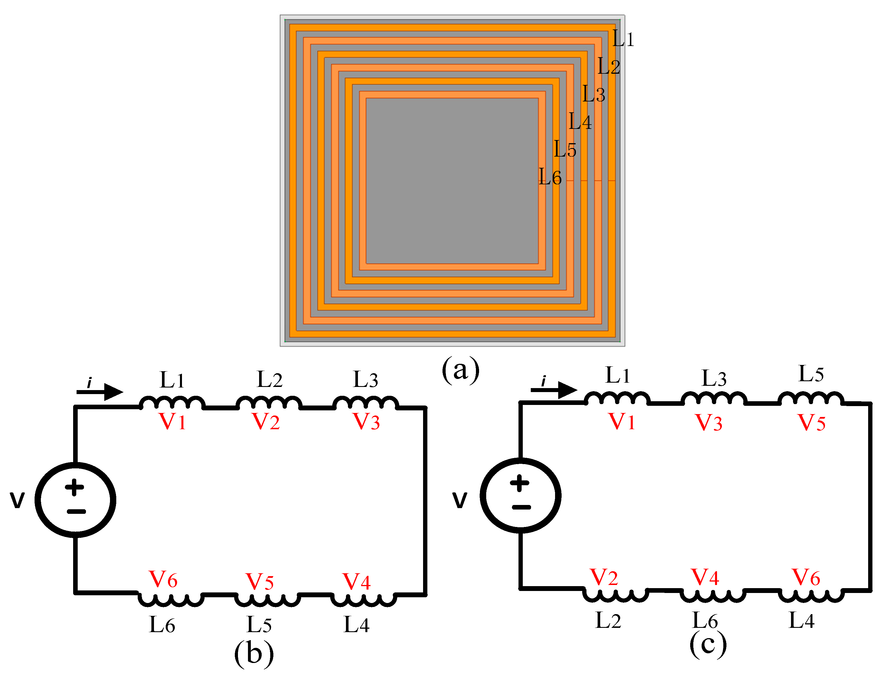
2. Proposed Coil Structure Compared to the Traditional Coil
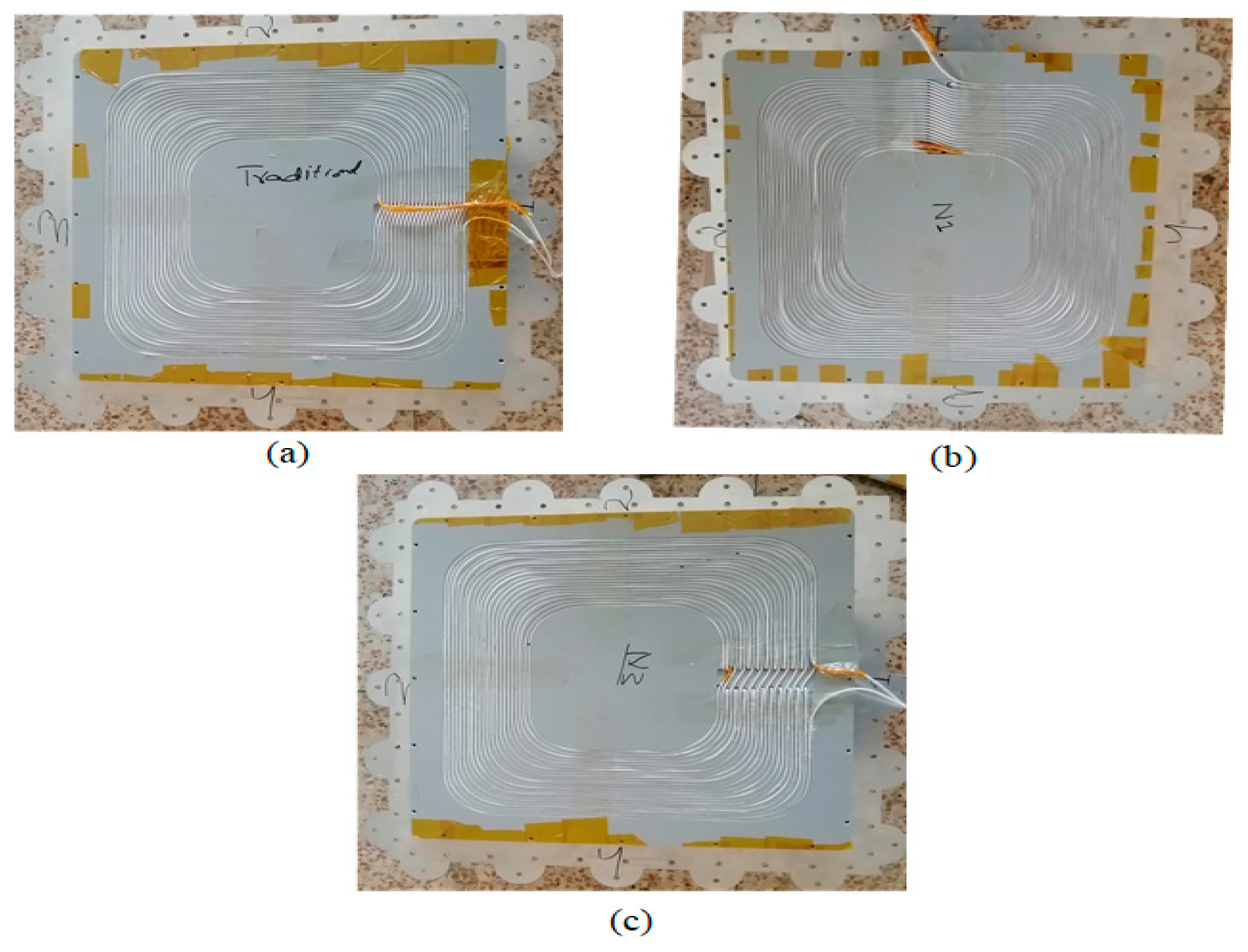
2.1. Structural Design and Development of AVPC
2.2. Simulation Setup and Preliminary Results
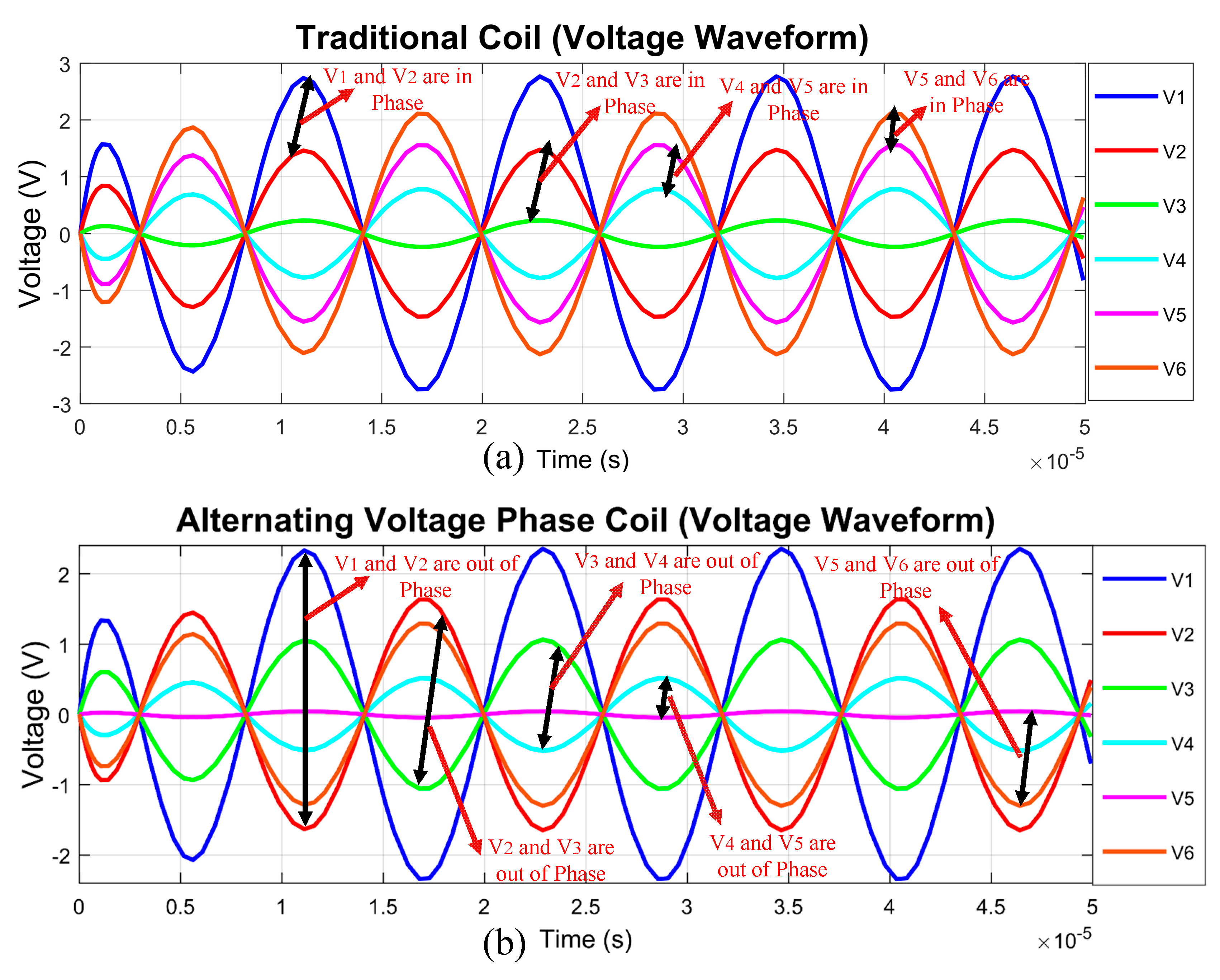
2.3. Waveform Analysis and E-Field Mitigation through Spice Simulation
3. Simulation Analysis of the Coil
3.1. Simulation Parameters and Setup
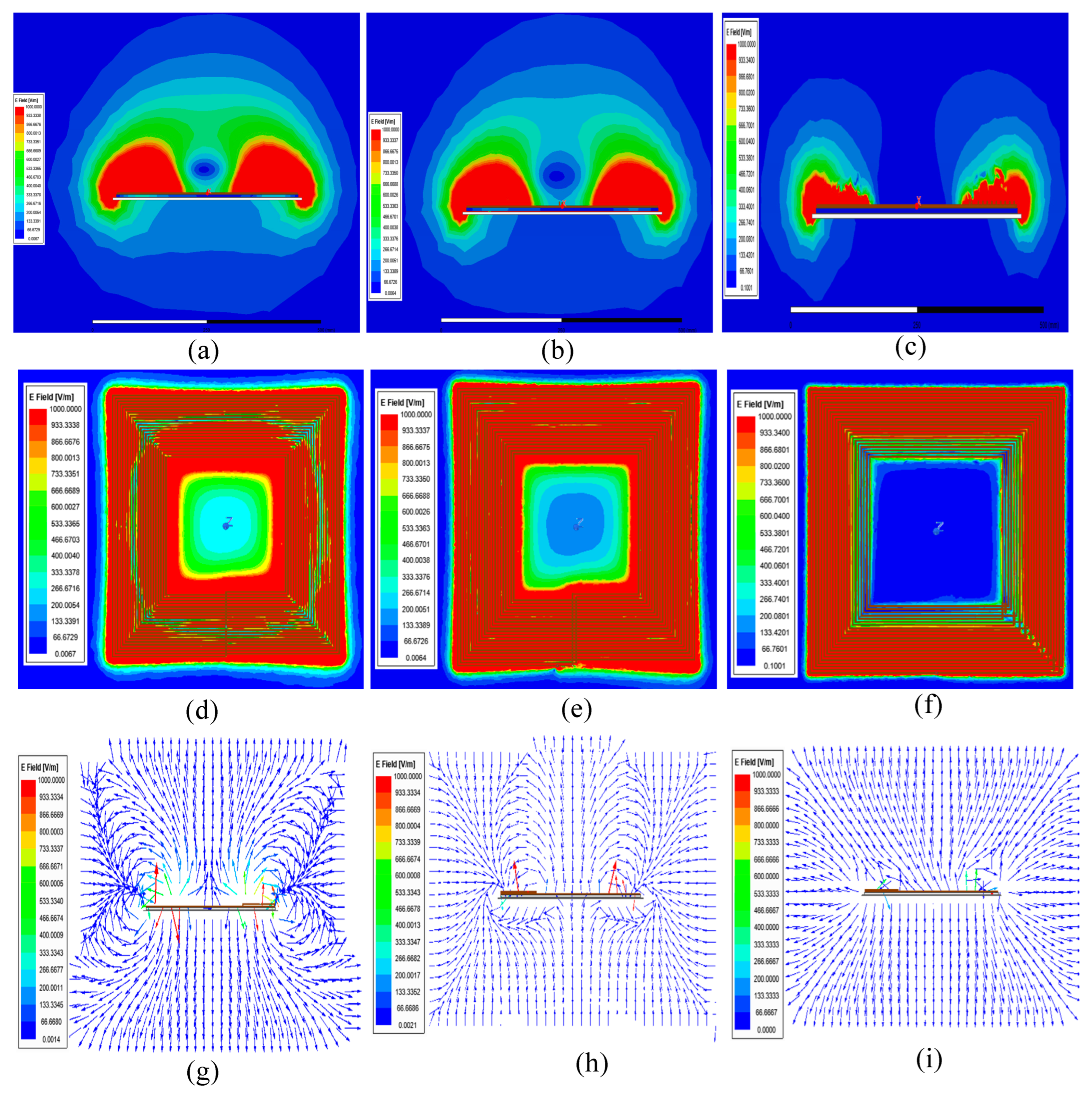
3.2. Electromagnetic Field Distribution and the Impact of Conductive Materials
3.3. Evaluating Electric Field Mitigation and Similar Magnetic Field Distribution in Coil Design
4. Experimental Setup of Coil Design and Result Verification
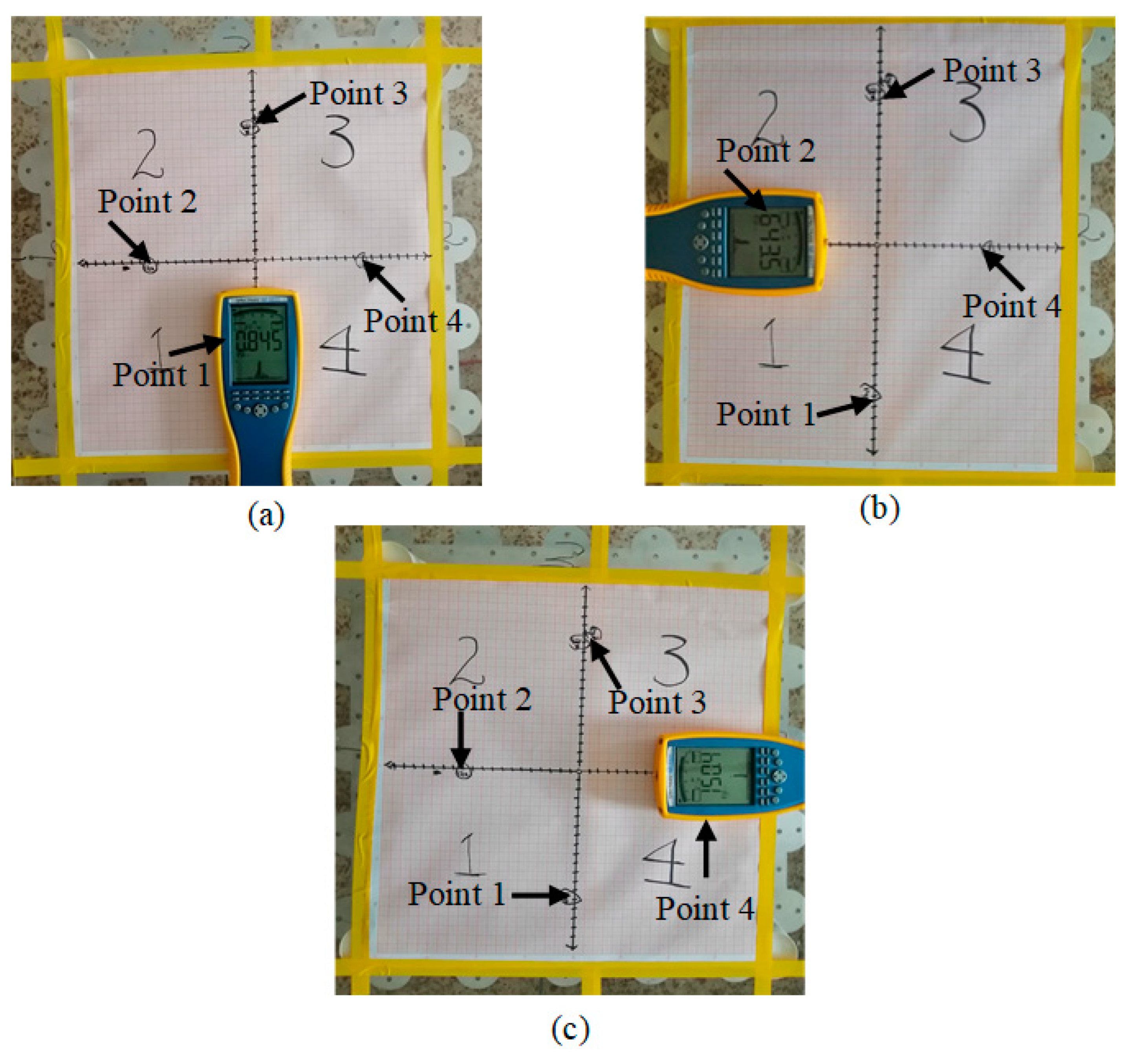
4.1. Methodical Assessment and Verification of Coil Design Performance
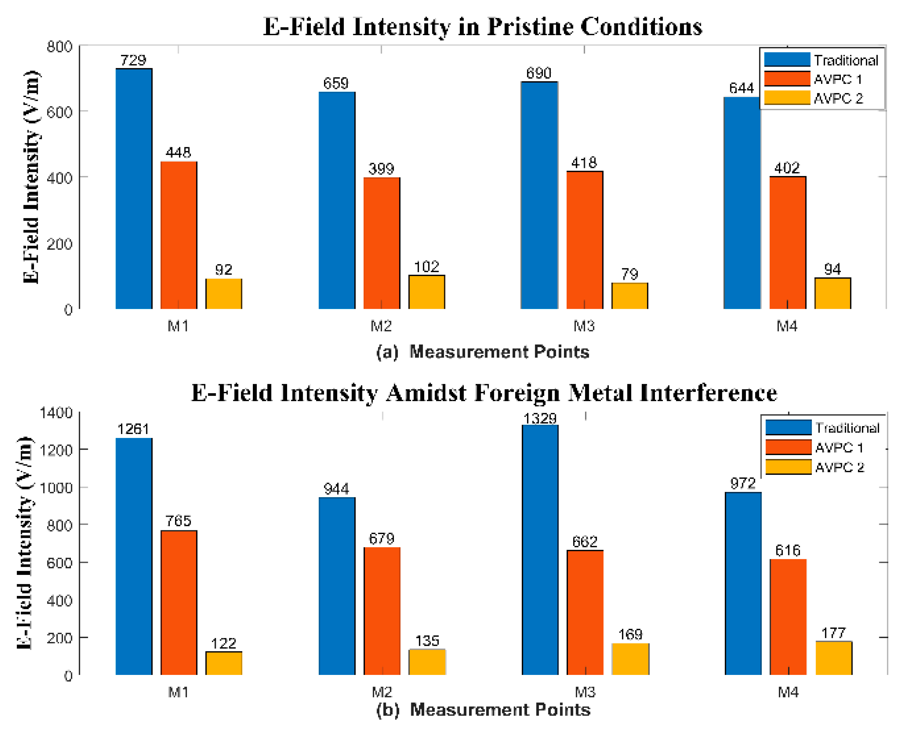
4.2. Detailed Analysis of E-Field Emission Findings
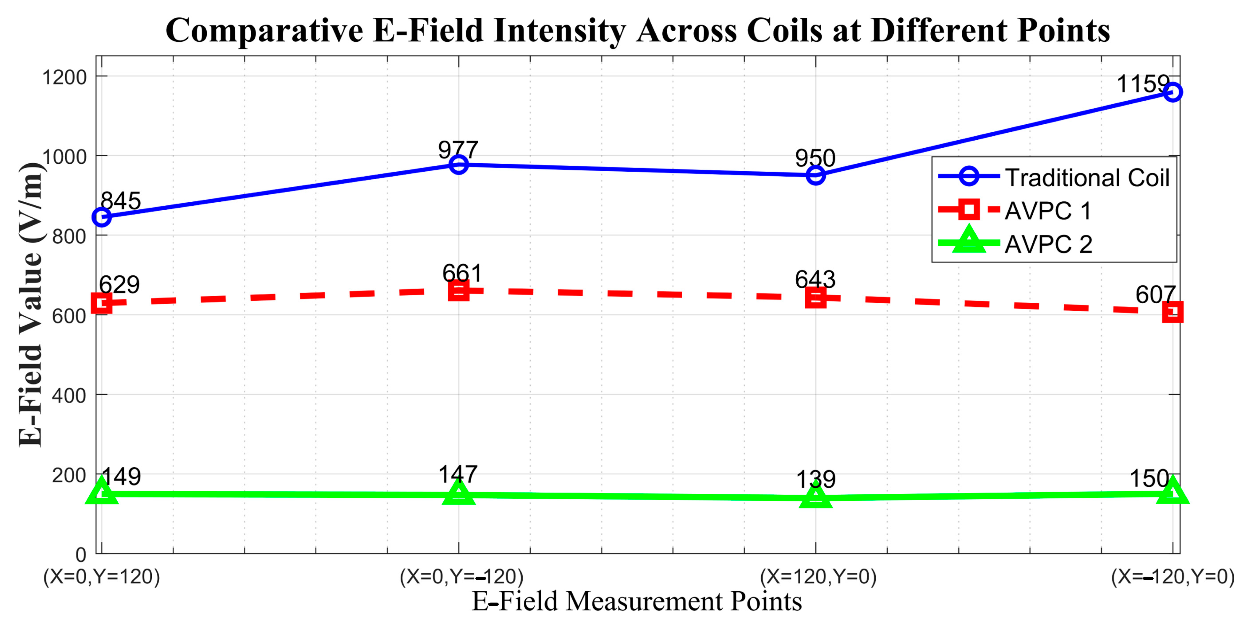
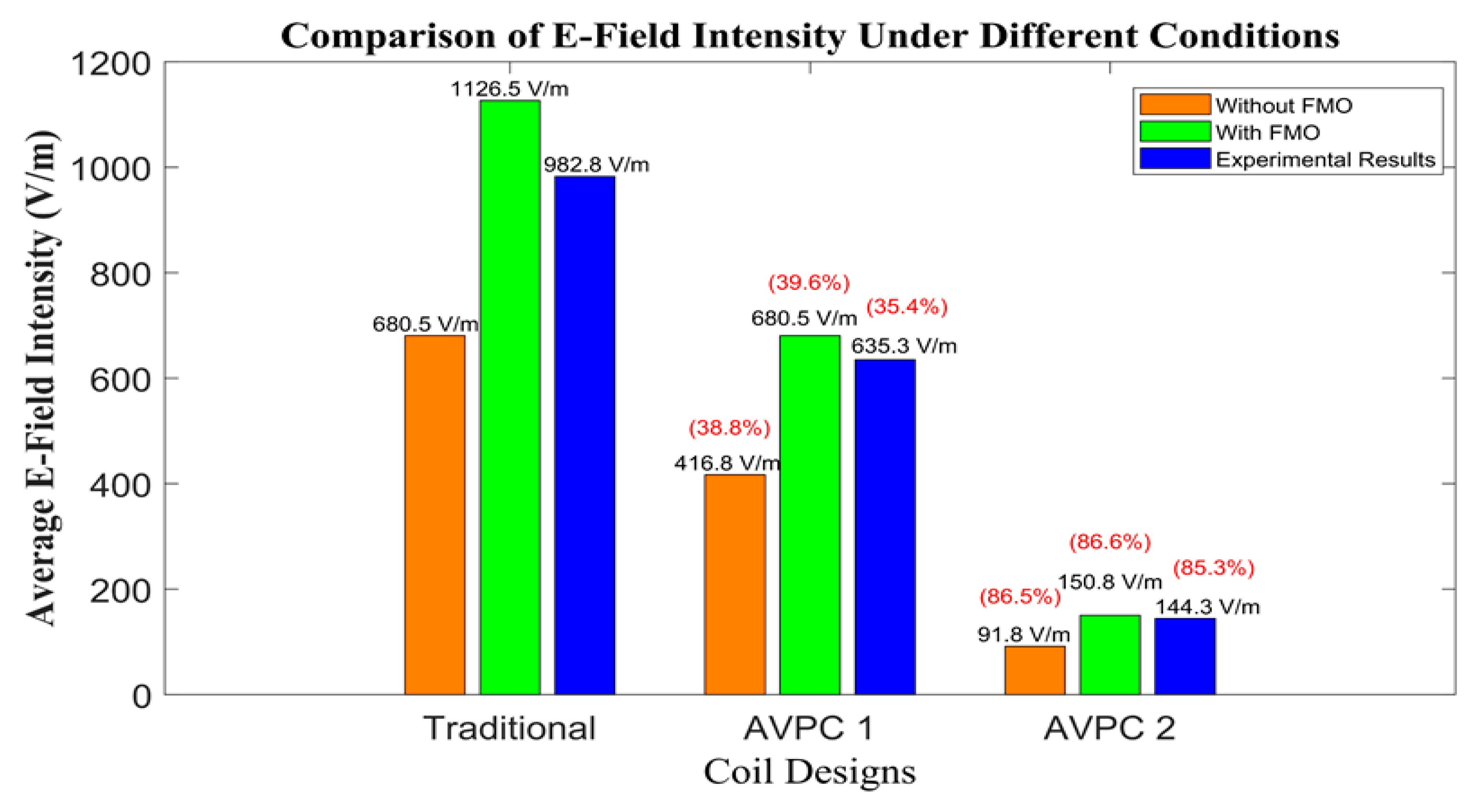
4.3. Quantitative Assessment of E-Field Mitigation in AVPC Designs
5. Conclusions
Author Contributions
Funding
Data Availability Statement
Conflicts of Interest
References
- Jawad, A.M.; Nordin, R.; Gharghan, S.K.; Jawad, H.M.; Ismail, M. Opportunities and Challenges for Near-Field Wireless Power Transfer: A Review. Energies 2017, 10, 1022. [Google Scholar] [CrossRef]
- Barman, S.D.; Reza, A.W.; Kumar, N.; Karim, M.E.; Munir, A.B. Wireless Powering by Magnetic Resonant Coupling: Recent Trends in Wireless Power Transfer System and Its Applications. Renew. Sustain. Energy Rev. 2015, 51, 1525–1552. [Google Scholar] [CrossRef]
- Hui, S.Y.R.; Zhong, W.; Lee, C.K. A Critical Review of Recent Progress in Mid-Range Wireless Power Transfer. IEEE Trans. Power Electron. 2014, 29, 4500–4511. [Google Scholar] [CrossRef]
- Covic, G.A.; Boys, J.T. Modern Trends in Inductive Power Transfer for Transportation Applications. IEEE J. Emerg. Sel. Top. Power Electron. 2013, 1, 28–41. [Google Scholar] [CrossRef]
- Chopra, S.; Bauer, P. Driving Range Extension of EV With On-Road Contactless Power Transfer—A Case Study. IEEE Trans. Ind. Electron. 2013, 60, 329–338. [Google Scholar] [CrossRef]
- Xia, J.; Yuan, X.; Lu, S.; Dai, W.; Li, T.; Li, J.; Li, S. A General Parameter Optimization Method for a Capacitive Power Transfer System with an Asymmetrical Structure. Electronics 2022, 11, 922. [Google Scholar] [CrossRef]
- Dai, J.; Ludois, D.C. A Survey of Wireless Power Transfer and a Critical Comparison of Inductive and Capacitive Coupling for Small Gap Applications. IEEE Trans. Power Electron. 2015, 30, 6017–6029. [Google Scholar] [CrossRef]
- Kim, J.; Kim, D.-H.; Park, Y.-J. Analysis of Capacitive Impedance Matching Networks for Simultaneous Wireless Power Transfer to Multiple Devices. IEEE Trans. Ind. Electron. 2015, 62, 2807–2813. [Google Scholar] [CrossRef]
- Li, T.; Li, S.; Liu, Z.; Fang, Y.; Xiao, Z.; Shafiq, Z.; Lu, S. Enhancing V2G Applications: Analysis and Optimization of a CC/CV Bidirectional IPT System with Wide Range ZVS. IEEE Trans. Transp. Electrific. 2024, 1. [Google Scholar] [CrossRef]
- Cruciani, S.; Campi, T.; Maradei, F.; Feliziani, M. Wireless Charging in Electric Vehicles: EMI/EMC Risk Mitigation in Pacemakers by Active Coils. In Proceedings of the 2019 IEEE PELS Workshop on Emerging Technologies: Wireless Power Transfer (WoW), London, UK, 18–21 June 2019; IEEE: London, UK, 2019; pp. 173–176. [Google Scholar]
- Lu, X.; Wang, P.; Niyato, D.; Kim, D.I.; Han, Z. Wireless Charging Technologies: Fundamentals, Standards, and Network Applications. IEEE Commun. Surv. Tutor. 2016, 18, 1413–1452. [Google Scholar] [CrossRef]
- Kalwar, K.A.; Aamir, M.; Mekhilef, S. Inductively Coupled Power Transfer (ICPT) for Electric Vehicle Charging—A Review. Renew. Sustain. Energy Rev. 2015, 47, 462–475. [Google Scholar] [CrossRef]
- Li, S.; Yu, X.; Yuan, Y.; Lu, S.; Li, T. A Novel High-Voltage Power Supply With MHz WPT Techniques: Achieving High-Efficiency, High-Isolation, and High-Power-Density. IEEE Trans. Power Electron. 2023, 38, 14794–14805. [Google Scholar] [CrossRef]
- Yashima, Y.; Omori, H.; Morizane, T.; Kimura, N.; Nakaoka, M. Leakage Magnetic Field Reduction from Wireless Power Transfer System Embedding New Eddy Current-Based Shielding Method. In Proceedings of the 2015 International Conference on Electrical Drives and Power Electronics (EDPE), Tatranska Lomnica, Slovakia, 21–23 September 2015; IEEE: Tatranska Lomnica, Slovakia, 2015; pp. 241–245. [Google Scholar]
- Deng, J.; Li, W.; Nguyen, T.D.; Li, S.; Mi, C.C. Compact and Efficient Bipolar Coupler for Wireless Power Chargers: Design and Analysis. IEEE Trans. Power Electron. 2015, 30, 6130–6140. [Google Scholar] [CrossRef]
- Mei, Y.; Wu, J.; He, X. Common Mode Noise Analysis for Inductive Power Transfer System Based on Distributed Stray Capacitance Model. IEEE Trans. Power Electron. 2022, 37, 1132–1145. [Google Scholar] [CrossRef]
- Estrada, J.; Sinha, S.; Regensburger, B.; Afridi, K.; Popovic, Z. Capacitive Wireless Powering for Electric Vehicles with Near-Field Phased Arrays. In Proceedings of the 2017 47th European Microwave Conference (EuMC), Nuremberg, Germany, 10–12 October 2017; IEEE: Nuremberg, Germany, 2017; pp. 196–199. [Google Scholar]
- Mai, J.; Wang, Y.; Zeng, X.; Yao, Y.; Wu, K.; Xu, D. A Multi-Segment Compensation Method for Improving Power Density of Long-Distance IPT System. IEEE Trans. Ind. Electron. 2022, 69, 12795–12806. [Google Scholar] [CrossRef]
- Shafiq, Z.; Xia, J.; Min, Q.; Li, S.; Lu, S. Study of the Induced Electric Field Effect on Inductive Power Transfer System. In Proceedings of the 2021 IEEE PELS Workshop on Emerging Technologies: Wireless Power Transfer (WoW), San Diego, CA, USA, 1–4 June 2021; IEEE: San Diego, CA, USA, 2021; pp. 1–5. [Google Scholar]
- Kim, M.; Ahn, S.; Kim, H. Magnetic Design of a Three-Phase Wireless Power Transfer System for EMF Reduction. In Proceedings of the 2014 IEEE Wireless Power Transfer Conference, Jeju City, South Korea, 8–9 May 2014; IEEE: Jeju City, South Korea, 2014; pp. 17–20. [Google Scholar]
- Liu, Z.; Li, T.; Li, S.; Mi, C.C. Advancements and Challenges in Wireless Power Transfer: A Comprehensive Review. Nexus 2024, 1, 100014. [Google Scholar] [CrossRef]
- Choi, S.Y.; Gu, B.W.; Jeong, S.Y.; Rim, C.T. Advances in Wireless Power Transfer Systems for Roadway-Powered Electric Vehicles. IEEE J. Emerg. Sel. Top. Power Electron. 2015, 3, 18–36. [Google Scholar] [CrossRef]
- Budhia, M.; Covic, G.A.; Boys, J.T. Design and Optimization of Circular Magnetic Structures for Lumped Inductive Power Transfer Systems. IEEE Trans. Power Electron. 2011, 26, 3096–3108. [Google Scholar] [CrossRef]
- Kim, J.; Kim, J.; Kong, S.; Kim, H.; Suh, I.-S.; Suh, N.P.; Cho, D.-H.; Kim, J.; Ahn, S. Coil Design and Shielding Methods for a Magnetic Resonant Wireless Power Transfer System. Proc. IEEE 2013, 101, 1332–1342. [Google Scholar] [CrossRef]
- Siqi, L.; Mi, C. Wireless Power Transfer for Electric Vehicle Applications. IEEE J. Emerg. Sel. Top. Power Electron. 2015, 3, 4–17. [Google Scholar] [CrossRef]
- Campi, T.; Cruciani, S.; Maradei, F.; Feliziani, M. Near-Field Reduction in a Wireless Power Transfer System Using LCC Compensation. IEEE Trans. Electromagn. Compat. 2017, 59, 686–694. [Google Scholar] [CrossRef]
- Stepins, D.; Zakis, J.; Padmanaban, P.; Deveshkumar Shah, D. Suppression of Radiated Emissions from Inductive-Resonant Wireless Power Transfer Systems by Using Spread-Spectrum Technique. Electronics 2022, 11, 730. [Google Scholar] [CrossRef]
- Inoue, K.; Kusaka, K.; Itoh, J.-I. Reduction in Radiation Noise Level for Inductive Power Transfer Systems Using Spread Spectrum Techniques. IEEE Trans. Power Electron. 2018, 33, 3076–3085. [Google Scholar] [CrossRef]
- Park, S. Evaluation of Electromagnetic Exposure During 85 kHz Wireless Power Transfer for Electric Vehicles. IEEE Trans. Magn. 2018, 54, 5100208. [Google Scholar] [CrossRef]
- Duan, X.; Lan, J.; Kodera, S.; Kirchner, J.; Fischer, G.; Hirata, A. Wireless Power Transfer Systems With Composite Cores for Magnetic Field Shielding With Electric Vehicles. IEEE Access 2023, 11, 144887–144901. [Google Scholar] [CrossRef]
- Li, T.; Yuan, Y.; Xiao, Z.; Fang, Y.; Xingpeng, Y.; Li, S. Large Space Wireless Power Transfer System That Meets Human Electromagnetic Safety Limits. In Proceedings of the 2023 IEEE Wireless Power Technology Conference and Expo (WPTCE), San Diego, CA, USA, 4–8 June 2023; IEEE: San Diego, CA, USA, 2023; pp. 1–6. [Google Scholar]
- Guidelines on Limiting Exposure to Non-Ionizing Radiation: A Reference Book Based on the Guidelines on Limiting Exposure to Non-Ionizing Radiation and Statements on Special Applications; Matthes, R.; Bernhardt, J.H. (Eds.) ICNIRP; International Commission on Non-Ionizing Radiation Protection: Oberschleißheim, Germany, 1999; ISBN 978-3-9804789-6-0. [Google Scholar]
- International Commission on Non-Ionizing Radiation Protection. Guidelines for limiting exposure to time-varying electric and magnetic fields (1 Hz to 100 kHz). Health Phys. 2010, 99, 818–836. [Google Scholar] [CrossRef]
- Jo, M.; Sato, Y.; Kaneko, Y.; Abe, S. Methods for Reducing Leakage Electric Field of a Wireless Power Transfer System for Electric Vehicles. In Proceedings of the 2014 IEEE Energy Conversion Congress and Exposition (ECCE), Pittsburgh, PA, USA, 14–18 September 2014; IEEE: Pittsburgh, PA, USA, 2014; pp. 1762–1769. [Google Scholar]
- Wang, B.; Yerazunis, W.; Teo, K.H. Wireless Power Transfer: Metamaterials and Array of Coupled Resonators. Proc. IEEE 2013, 101, 1359–1368. [Google Scholar] [CrossRef]
- Sample, A.; Smith, J.R. Experimental Results with Two Wireless Power Transfer Systems. In Proceedings of the 2009 IEEE Radio and Wireless Symposium, San Diego, CA, USA, 18–22 January 2009; IEEE: San Diego, CA, USA, 2009; pp. 16–18. [Google Scholar]
- Sample, A.P.; Meyer, D.A.; Smith, J.R. Analysis, Experimental Results, and Range Adaptation of Magnetically Coupled Resonators for Wireless Power Transfer. IEEE Trans. Ind. Electron. 2011, 58, 544–554. [Google Scholar] [CrossRef]
- Shahjalal, M.; Shams, T.; Tasnim, M.N.; Ahmed, M.R.; Ahsan, M.; Haider, J. A Critical Review on Charging Technologies of Electric Vehicles. Energies 2022, 15, 8239. [Google Scholar] [CrossRef]
- Hayt, W. Engineering Electromagnetics. In Physical Constants; McGraw-Hill Companies: New York, NY, USA, 1974. [Google Scholar]
- Paul, C.R. Introduction to Electromagnetic Compatibility; John Wiley & Sons: Hoboken, NJ, USA, 2022. [Google Scholar]
- Tumanski, S. Induction Coil Sensors—A Review. Meas. Sci. Technol. 2007, 18, R31–R46. [Google Scholar] [CrossRef]
- Kurokawa, K. Power Waves and the Scattering Matrix. IEEE Trans. Microw. Theory Techn. 1965, 13, 194–202. [Google Scholar] [CrossRef]
- Sirbu, I.-G.; Mandache, L. Comparative Analysis of Different Topologies for Wireless Power Transfer Systems. In Proceedings of the 2017 IEEE International Conference on Environment and Electrical Engineering and 2017 IEEE Industrial and Commercial Power Systems Europe (EEEIC/I&CPS Europe), Milan, Italy, 6–9 June 2017; IEEE: Milan, Italy, 2017; pp. 1–6. [Google Scholar]


| Feature | Conventional Coil | AVPC |
|---|---|---|
| E-field emission reduction | Limited | Significantly improved |
| Energy transfer efficiency | High | Comparable to conventional coils |
| E-field neutralization method | Capacitors (complex) | Design configuration |
| Innovative current flow sequence | No | Yes |
| Sequential turn progression | Turns in sequence | Not applicable |
| Adaptability to various devices | Limited | Broad (EVs, mobiles, medical equipment) |
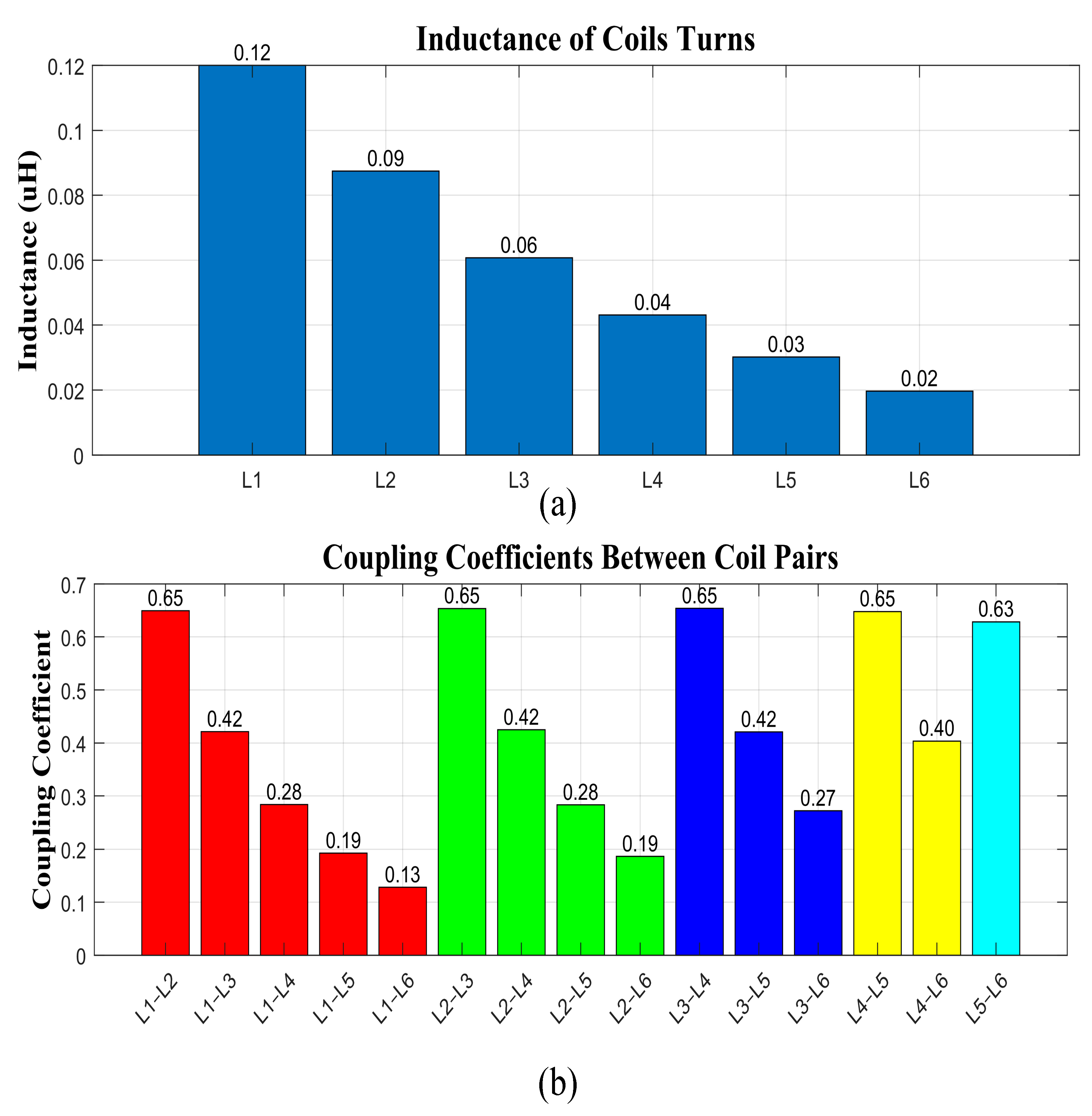
| Coil | Inductance (uH) | Parameter | Value |
|---|---|---|---|
| L1 | 0.120 | Input AC current I | 5 A |
| L2 | 0.087469 | Resonant frequency | 85 KHz |
| L3 | 0.060760 | Shielding plate | 74 mm × 74 mm × 1 mm |
| L4 | 0.043119 | Ferrite core 1 | 72 mm × 72 mm × 2 mm |
| L5 | 0.030174 | Coil dimension | 70 mm × 70 mm × 3 mm |
| L6 | 0.019673 | Coil turn to turn spacing | 1.5 mm |
| Parameters | Values |
|---|---|
| Input AC current | 5 A |
| Resonant frequency | 85 KHz |
| Shielding plate dimension | 420 mm × 420 mm × 4 mm |
| Ferrite core dimension | 404 mm × 404 mm × 5 mm |
| Coil dimension | 400 mm × 400 mm × 2.5 mm |
| Number of turns | 22 Turns |
| Coil inductance | 336.4 uH |
Disclaimer/Publisher’s Note: The statements, opinions and data contained in all publications are solely those of the individual author(s) and contributor(s) and not of MDPI and/or the editor(s). MDPI and/or the editor(s) disclaim responsibility for any injury to people or property resulting from any ideas, methods, instructions or products referred to in the content. |
© 2024 by the authors. Licensee MDPI, Basel, Switzerland. This article is an open access article distributed under the terms and conditions of the Creative Commons Attribution (CC BY) license (https://creativecommons.org/licenses/by/4.0/).
Share and Cite
Shafiq, Z.; Li, T.; Xia, J.; Li, S.; Yang, X.; Zhao, Y. Addressing EMI and EMF Challenges in EV Wireless Charging with the Alternating Voltage Phase Coil. Actuators 2024, 13, 324. https://doi.org/10.3390/act13090324
Shafiq Z, Li T, Xia J, Li S, Yang X, Zhao Y. Addressing EMI and EMF Challenges in EV Wireless Charging with the Alternating Voltage Phase Coil. Actuators. 2024; 13(9):324. https://doi.org/10.3390/act13090324
Chicago/Turabian StyleShafiq, Zeeshan, Tong Li, Jinglin Xia, Siqi Li, Xi Yang, and Yu Zhao. 2024. "Addressing EMI and EMF Challenges in EV Wireless Charging with the Alternating Voltage Phase Coil" Actuators 13, no. 9: 324. https://doi.org/10.3390/act13090324