Abstract
In response to problems such as insufficient adhesion, difficulty in adjustment, and weak obstacle-crossing capabilities in traditional robots, an innovative design has been developed for a five-wheeled climbing robot equipped with a pendulum-style magnetic control adsorption module. This design effectively reduces the weight of the robot, and sensors on the magnetic adsorption module enable real-time monitoring of magnetic force. Intelligent control adjusts the pendulum angle to modify the magnetic force according to different wall conditions. The magnetic adsorption module, using a Halbach array, enhances the concentration effect of the magnetic field, ensuring excellent performance in high-load tasks such as building maintenance, bridge inspection, and ship cleaning. The five-wheel structural design enhances the stability and obstacle-crossing capability, making it suitable for all-terrain environments. Simulation experiments using Maxwell analyzed the effects of the magnetic gap and the angle between the adsorption module and the wall, and mechanical performance analysis confirmed the robot’s ability to adhere safely and operate stably.
1. Introduction
With the continuous advancement of science and technology, robotics has made tremendous progress and has shown great potential for application in various fields [1,2]. Wall-climbing robots are special robots, which are important branches in the field of robotics, which comprehensively utilize various technologies such as mobile technology, adsorption technology, and control [3]. Scholars have conducted a lot of research on wall-climbing robots, and the adsorption methods are mainly divided into three types: negative pressure adsorption, bionic adsorption, and magnetic adsorption. Originally, Professor Ryo Nishi of Japan developed a wall-climbing robot in 1966, which uses the negative pressure adsorption principle generated by the rotation of the electric fan to make it adsorb on the wall. Since then, other countries have also joined the research of wall-climbing robots. Wall-climbing robots can crawl on vertical, curved, and corner walls and carry specific equipment to complete dangerous work such as cleaning, testing, and welding of special machinery [4]. In addition, the robot adsorbed on the overhanging wall, compared with manual inspection, has the outstanding advantages of strong safety and high detection efficiency and has attracted more and more attention in the field of wall inspection [5,6,7,8], which can be completed instead of humans to ensure personal safety, and has important applications in industry and shipbuilding.
In the design of wall-climbing robots, adsorption technology is a crucial element. Permanent magnet adsorption, as a common method, offers advantages such as a simple structure and stable operation, making it widely recognized. The structural forms of magnetic adsorption mechanisms are mainly categorized into flat-plate and wheel types. The flat-plate type consists of a rectangular permanent magnet mechanism, typically embedded in the tracks. Robots using annular array magnetic wheels often experience significant magnetic leakage and low magnetic energy utilization, leading to energy waste. Although existing wall-climbing robot technologies have been widely applied in industrial inspections, they often face limitations such as insufficient adsorption force and difficulty adapting to complex surfaces. This study significantly enhances the robot’s stability and adsorption efficiency on various surfaces by employing a Halbach array and a suspension-type magnetic-controlled adsorption mechanism. The study conducts an in-depth analysis and validation of the factors influencing the permanent magnet adsorption performance of wall-climbing robots, providing theoretical and practical support for improving the adsorption efficiency and stability of these robots.
Through data analysis, the influencing factors and their mechanisms are clarified, which provides a practical, theoretical basis and technical support for future design optimization and provides technical support and guidance for practical engineering applications so as to promote the further development and application of wall-climbing robot technology.
2. Wall-Climbing Robot Design
2.1. Structural Design
In order to meet the special working scene of flexible movement and steering of the wall-climbing robot on the wall, the wheeled movement mode is adopted, which not only avoids the shortcomings of large crawler volume and difficult steering but also avoids the disadvantages of foot-type structure and complex control [9,10]. Common adsorption methods are mainly divided into three categories: magnetic adsorption, negative pressure adsorption, and bionic adsorption [11]. For metal walls, magnetic adsorption has the advantages of energy saving, no heat, no noise, safety, and low cost compared with other adsorption methods [12]. In order to ensure that the wall-climbing robot can be safely adsorbed on the wall surface and at the same time meet the requirements of a simple and lightweight structure, the permanent magnet unit is composed of NdFeB rare earth permanent magnet material, which will not be dangerous due to power failure like electromagnetic structure.
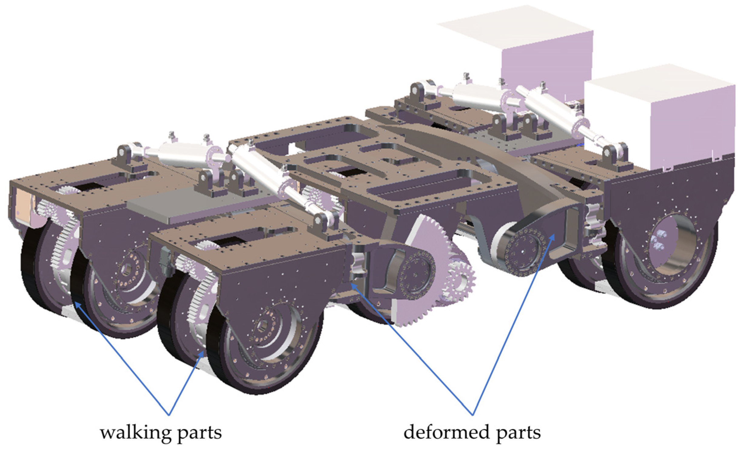
As shown in Figure 1, the wall-climbing robot mainly consists of walking parts and deformed parts. This division clarifies the functions and interactions of each part, which is crucial for the overall design.
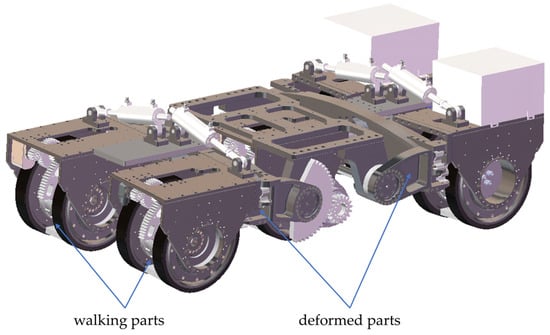
Figure 1.
The overall structure of the wall-climbing robot.
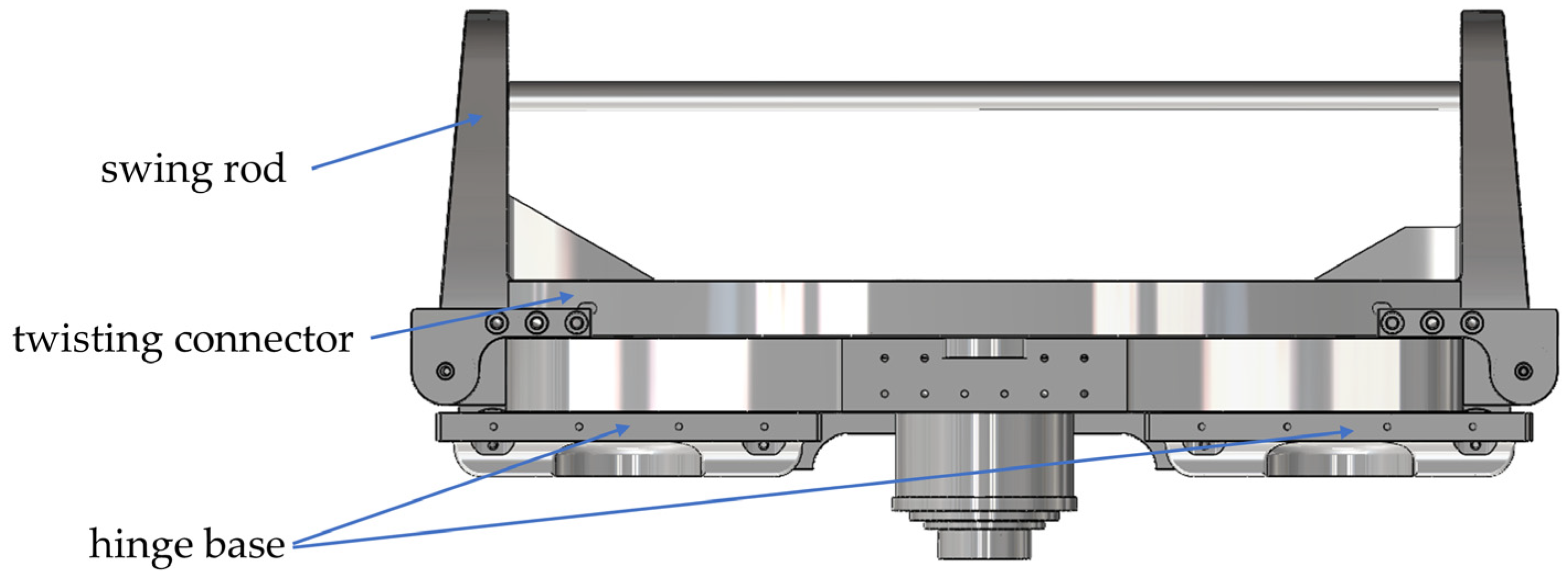
The walking parts and deformed parts are symmetrically distributed. Figure 2 shows the specific structure of the deformed parts, where the design of the swing rod allows the two front walking parts to lift appropriately when encountering obstacles, thereby overcoming them. The walking parts are connected to the swing rod through twisting connectors, allowing the walking parts to rotate around the wheel set’s axis to adjust the angle between the wheels and the contact surface. This design enhances the robot’s ability to adapt to different terrains, allowing it to walk on vertical and curved surfaces. The mechanism parameters of the wall-climbing robot are shown in Table 1.
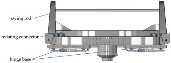
Figure 2.
Structure diagram of deformed parts.

Table 1.
Structural parameters of wall-climbing robots.
Compared to traditional three- or four-wheeled climbing robots, the five-wheeled design significantly improves stability, better distributes the robot’s weight, and improves maneuverability on uneven and vertical surfaces, which is a common challenge in real-world environments such as hulls and industrial complexes.
2.2. Magnetic Chuck Design
The core technology of the wall-climbing robot relies on the interaction between the magnetic suction unit and the wall, which enables the robot to closely adhere to and move on the wall by generating a strong magnetic attraction, and its performance depends on the selected magnetic material and magnetic circuit design [13]. The magnetic suction unit is composed of high-performance NdFeB permanent magnets (NdFe35), which ensures that the robot remains stable under various special working conditions. The traditional magnetic attraction method is to achieve magnetic attraction adsorption through the magnetic wheel; the permanent magnet wheel is usually composed of a whole magnet, its magnetic field is symmetrically distributed, its weight is large, and the magnetic energy utilization rate is low. Only the magnetic wheel and the wall contact part produce magnetic force, and the magnetic attraction force is very small. The designed magnetic suction unit is suspended between the two wheels by the connecting shaft between the driving wheels, which replaces the traditional permanent magnet design on the wheels, effectively reduces the overall weight, improves the magnetic mass ratio, and thus improves the utilization rate of magnetic energy.
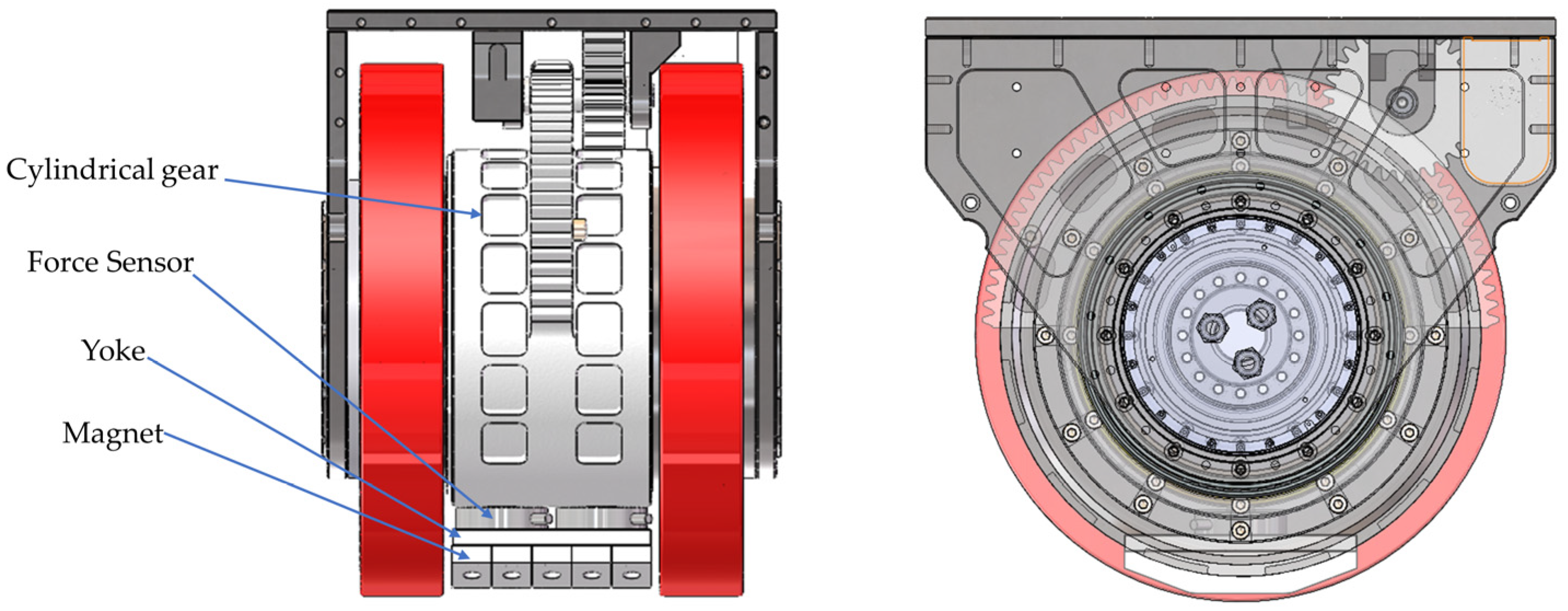
The force sensors monitor the magnetic attraction force in real time while a motor rotates a cylindrical gear to drive the magnetic chuck to the appropriate position. This rotation adjusts the angle between the magnet and the yoke, thereby altering the magnetic attraction force between the wall-climbing robot and the wall. This ensures attachment stability under various wall conditions. Maximum magnetic attraction force is generated when the surface is parallel to the wall, and the magnetic attraction force decreases when the magnetic chuck is at an angle to the wall. The structure is shown in Figure 3.
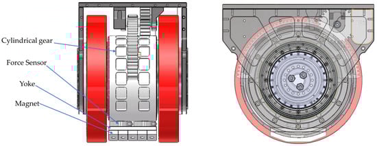
Figure 3.
Schematic diagram of the magnetic adsorption unit structure.
The specific parameters of the magnetic suction unit are shown in Table 2 below.
Table 2.
Parameters of magnetic suction units.
The permanent magnet and the conductive magnet are arranged in a variety of different ways to make more magnetic flux converge into the working air gap to improve the utilization rate of the permanent magnet. The Halbach-type permanent magnet array was first discovered and proposed by Klaus Halbach of the United States [14], with good uniformity and reduced self-weight.
During the design process, stability, flexibility, and magnetic attraction are mainly considered:
- (1)
- The five-wheel design can improve the stability of the robot in vertical and inclined planes and avoid tipping over.
- (2)
- The deformed parts allow the robot to adjust its attitude and adapt to different wall angles to enhance its adaptability.
- (3)
- The adsorption angle is adjusted by the pendulum magnetic suction mechanism to improve the adsorption efficiency and ensure adhesion stability under different wall conditions.
The pendulum magnetron adsorption module marks a significant improvement over traditional stationary magnetic systems. By allowing the magnetic force to be dynamically adjusted according to surface conditions, this design improves the safety and efficiency of the operation of complex structures. The simulation results show that the magnetic adhesion is significantly increased, especially on irregular surfaces, where conventional systems may not be able to maintain sufficient contact.
In order to explore whether the designed magnetic chuck meets the safety requirements, the following simulation will be based on Maxwell and the influence of the distance between the magnetic chuck and the wall on the magnetic attraction and the angle between the magnetic chuck and the wall will be explored, respectively.
2.3. Magnetic Suction Simulation Based on Maxwell
2.3.1. Analysis of the Influence of Air Gap Distance on Magnetic Attraction
In order to obtain a large magnetic attraction and improve the performance under heavy load conditions, the permanent magnet is made of NdFeB material, and the yoke iron and metal wall are made of steel_1008 structural steel. The performance parameters of the selected NdFeB materials are shown in Table 3 below.
Table 3.
NdFe35 neodymium iron boron performance parameters.
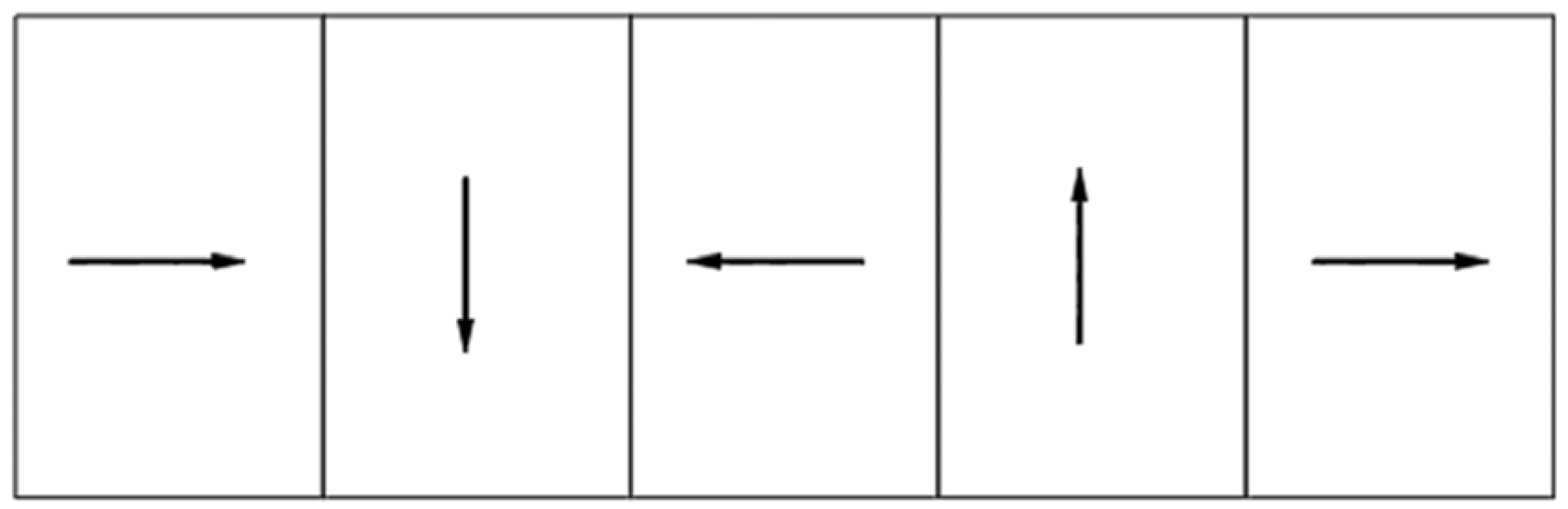
Compared with the traditional arrangement of magnets that are magnetized in the same direction, that is, the plate-type static magnetic field. The Halbach array has better space and material utilization. Two types of magnets with the same volume produce a much stronger magnetic field than the plate type [15]. The principle is to combine permanent magnets with different magnetization directions according to certain rules and superimpose the two magnetization methods of ordinary tangential magnetization and radial magnetization. A more ideal sinusoidal distributed magnetic field can be obtained, the structure of which is shown in Figure 4.

Figure 4.
Magnetization schematic of stacking method.
The magnetic field of the obtained magnet has the characteristics of obvious enhancement on one side and obvious weakening on the other side [16]. The comparison of the magnetic induction intensity on both sides is shown in Figure 5.
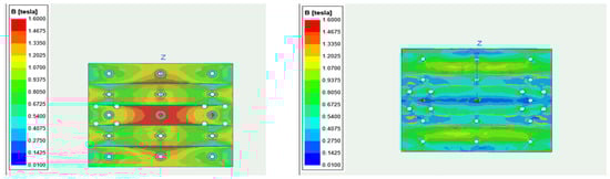
Figure 5.
The magnetic induction intensity contour map of the front and back sides of the magnetic chuck.
Simulation analysis of magnetic attraction force was conducted using ANSYS-Maxwell software to calculate the magnetic attraction force of the magnet on the metal wall. Simulation analysis: Magnetic force simulation was performed using Ansys Electronics Desktop—Maxwell software, with the following simulation steps:
- Create a model of the magnetic element and set the material properties, the yoke iron and steel plate materials are Steel_1008, and the permanent magnet materials are NdFe35.
- The permanent magnet material is magnetized according to the Halbach arrangement.
- Establish a closed simulation space, i.e., boundary conditions, and offset 20% outward in the XYZ direction according to the maximum volume of the model, and then mesh the yoke iron and steel plate to 10 mm.
- Set the magnetic gap range from 1 mm to 20 mm, and the angle between the magnetic unit and the wall clamp is 0~45°.
- Run the simulation to record the magnetic attraction at different parameters.
- Analyze the simulation results and plot the magnetic attraction as a function of the gap and angle.
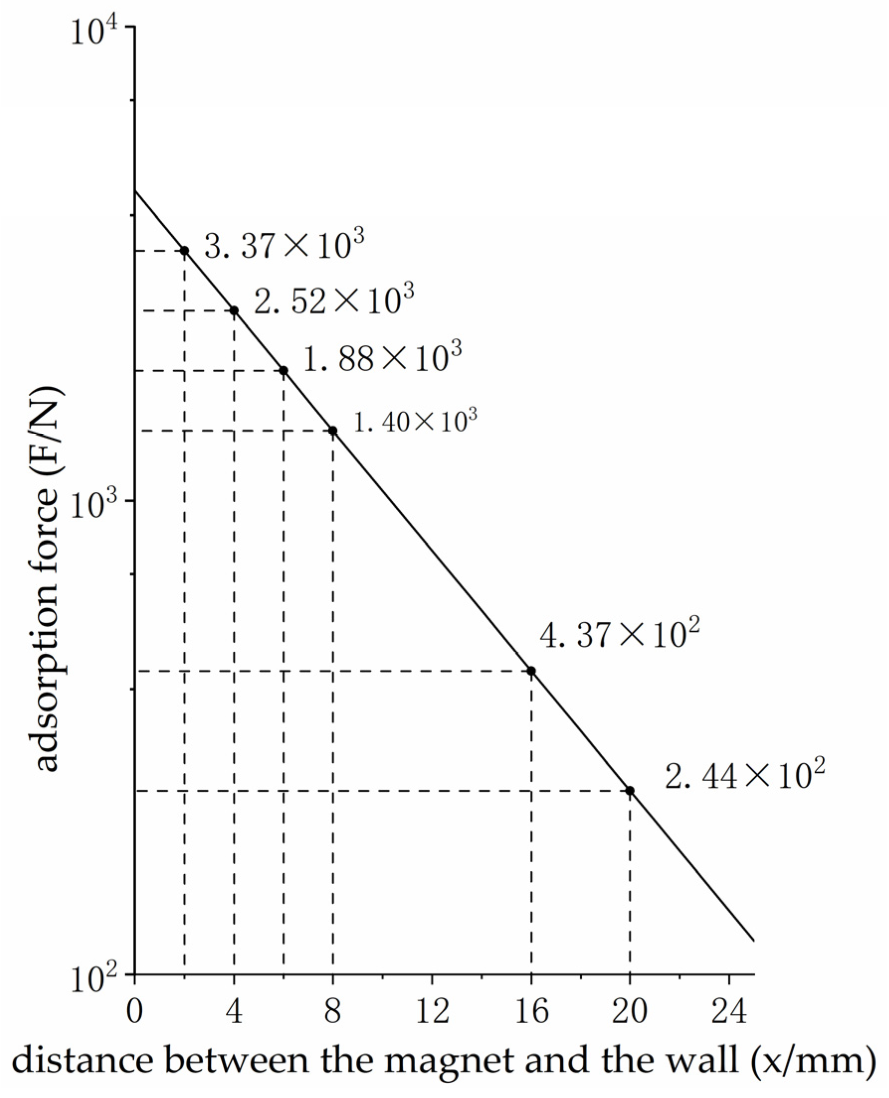
When the magnetic unit is 5.5 mm away from the wall, the magnetic attraction force of the structural simulation using the Halbach array is 1994 N, while the traditional directional consistency magnetization simulation result is 1012.6 N, and the magnetic energy utilization rate is increased by 97.2%, which shows the significant effect of the Halbach array on the magnetic field focusing. The relationship between the magnet and the wall and the magnetic attraction is shown in Figure 6.
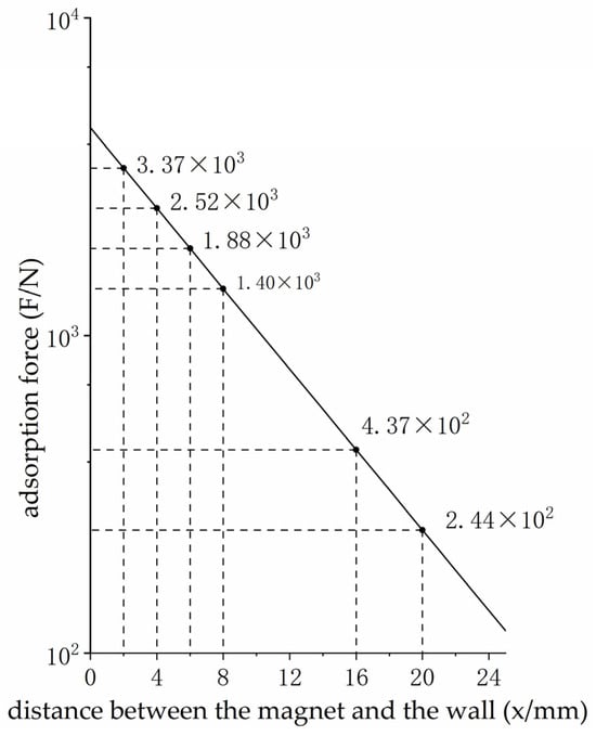
Figure 6.
Relationship between magnet and wall spacing and magnetic attraction.
Fitting the above data, the relationship between the distance between the magnet and the wall and the magnetic attraction is obtained.
with a gap of 8 mm, Maxwell simulation showed a magnetic attraction of 1400.7 N, while the magnetic attraction predicted by the exponential attenuation fitting model was 1404.5 N, with a corresponding error of only 0.271%, showing a high degree of accuracy of the model. In addition, the model had a goodness-of-fit (R2) of 0.9986, a value that reflects the proportion of total variation explained by the model, indicating that the agreement between the fit curve and the experimental data is extremely high. This high R2 value confirms the reliability of the model in predicting the magnetic attraction simulation results at different clearances.
Simulation analysis highlights the advantages of the pendulum magnetron adsorption module in maintaining high adhesion across a wide range of surface angles and types. This feature is critical for tasks that require high reliability, such as bridge inspections and high-rise building maintenance, as previous technologies may not provide adequate performance.
2.3.2. Effect of the Relative Wall Angle of the Magnet on the Magnetic Attraction
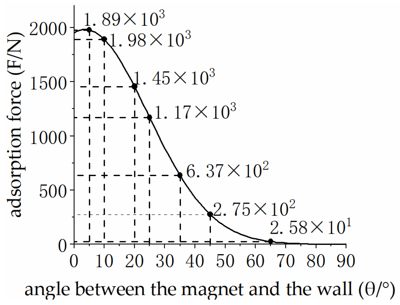
As a kind of special robot, the wall-climbing robot often has to adapt to various complex working conditions and wall transitions. Completing the wall chamfer transition is a big problem, and Maxwell was used to simulate and analyze the wall-climbing robot during the right-angle transition. During the rotation of the magnetic structure, the horizontal and vertical forces are constantly changing, so it is necessary to measure the magnetic attraction at all angles first. The horizontal force and the vertical force are symmetrical processes in the change of the magnetic structure from 0~90°, so only the horizontal and vertical directions in the range of 0~45° need to be measured, and the results are shown in Figure 7.
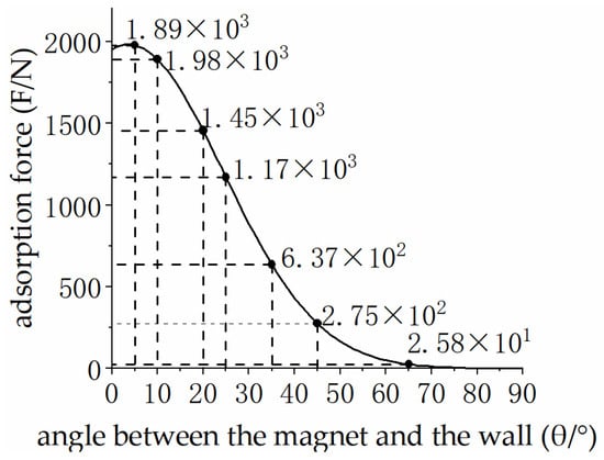
Figure 7.
Vertical force variation during the angular transition.
The data fitting of the simulation results is carried out, and the relationship between the rotation angle of the magnet and the force in the vertical direction is obtained.
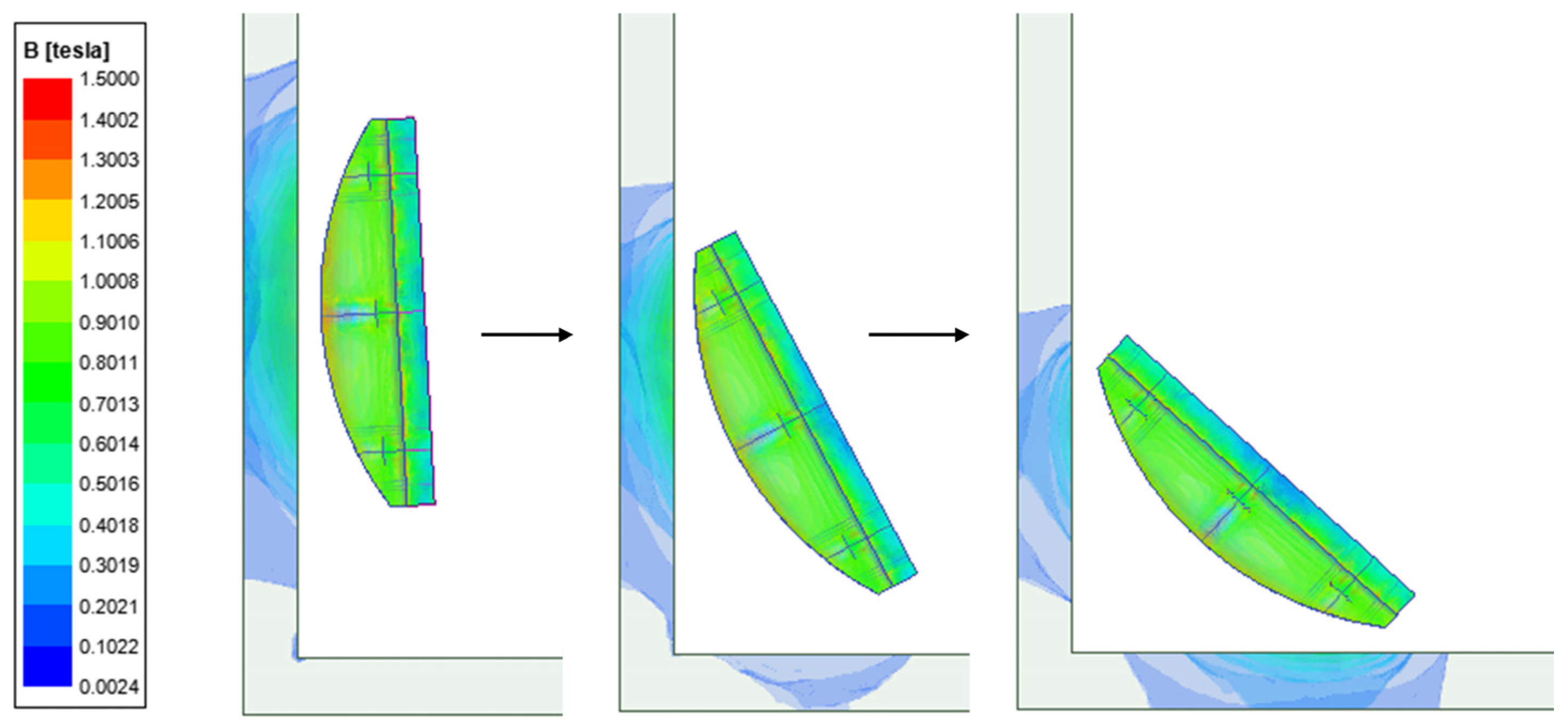
The R2 of the above fitting is 0.9998, and the fitting effect is superior. As shown in Figure 8, when the robot transitions at a right-angle wall, the magnetic induction intensity contour of the magnetic chuck shows that during the rotation process, the force in the vertical direction gradually decreases while the force in the horizontal direction gradually increases. This change has an important impact on the navigation and stability of the robot on complex wall surfaces, ensuring the adaptability and safety of the robot when performing tasks.

Figure 8.
Contour of magnetic induction intensity.
3. Analysis of Mechanical Properties of Five-Wheeled Wall-Climbing Robot
3.1. Robot Static Analysis
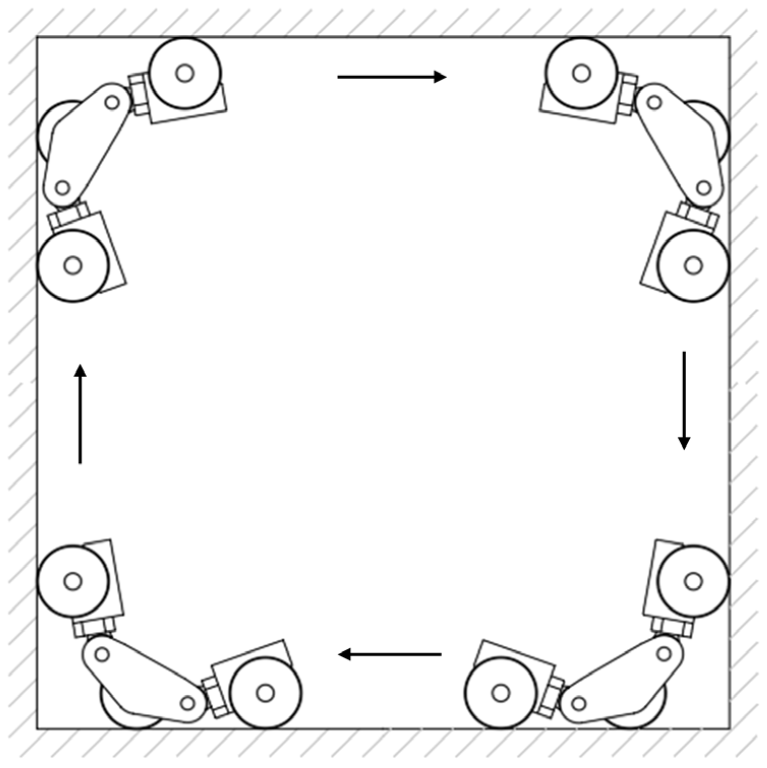
This section may be divided by subheadings. It should provide a concise and precise description of the experimental results, their interpretation, as well as the experimental conclusions that can be drawn. The designed five-wheeled wall-climbing magnetic robot can achieve a horizontal plane to a vertical plane, as well as an inner fold from the vertical plane to the ceiling and an outer fold from the vertical plane to the roof. The circumferential motion process of the inner fold angle is shown in Figure 9.
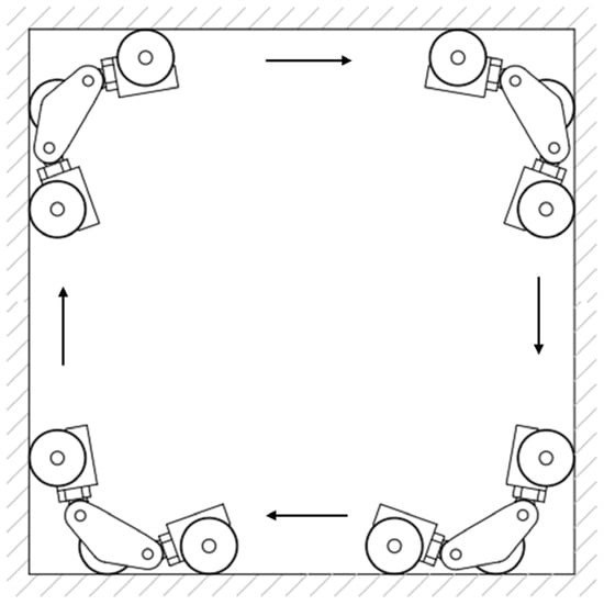
Figure 9.
Circumferential motion diagram of the internal folding angle.
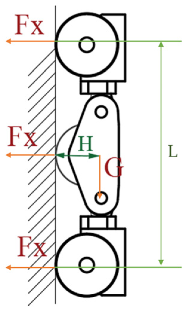
When the five-wheeled wall-climbing robot is adsorbed on the metal wall surface for movement, the horizontal plane movement is similar to that of ordinary wheeled robots driven by a motor, and basically, no failure will occur. If you move on a vertical wall, the direction of sliding can only be in the vertical direction, the support force of the robot will be reduced, and the friction will be weakened accordingly, so there must be enough magnetic attraction to generate enough friction to overcome the gravity of its own sliding (see Figure 10). The intermediate wheel has two magnetic chucks, so the conditions for not slipping on the vertical wall are as follows:

Figure 10.
Schematic diagram of the force under the vertical state of the robot.
Additionally, on vertical surfaces, the condition of moment balance must be met; otherwise, longitudinal overturning along the rear wheels may occur.
Calculating the torque at the contact point between the rear wheel and the wall.
L—the length between the two wheels of the wall-climbing robot is 910 mm;
H—the distance from the center of gravity of the robot to the wall is 150 mm;
M—The overall mass of the robot is 181.66 kg;
μ—The coefficient of static friction between the wheel and the wall is about 0.5.
Through the magnetic attraction data and calculations obtained from the simulation results, it can be seen that the robot can not slip and overturn on the vertical wall. In addition, the main forms of instability of the robot include failure in the transition from the horizontal ground to the vertical wall, the slipping and falling of the vertical wall and the dangerous working conditions caused by the magnetic force change during the vertical wall facing the ceiling. On both horizontal and vertical walls, the distance between the magnetic suction mechanism and the wall is usually constant, so there is almost no danger. In the process of the transition between the vertical wall and the ceiling, the magnetic force of the wall-climbing robot decreases sharply, and there is no ground support force to counteract gravity. The overall stress state and the minimum safe magnetic attraction under this condition are discussed below.
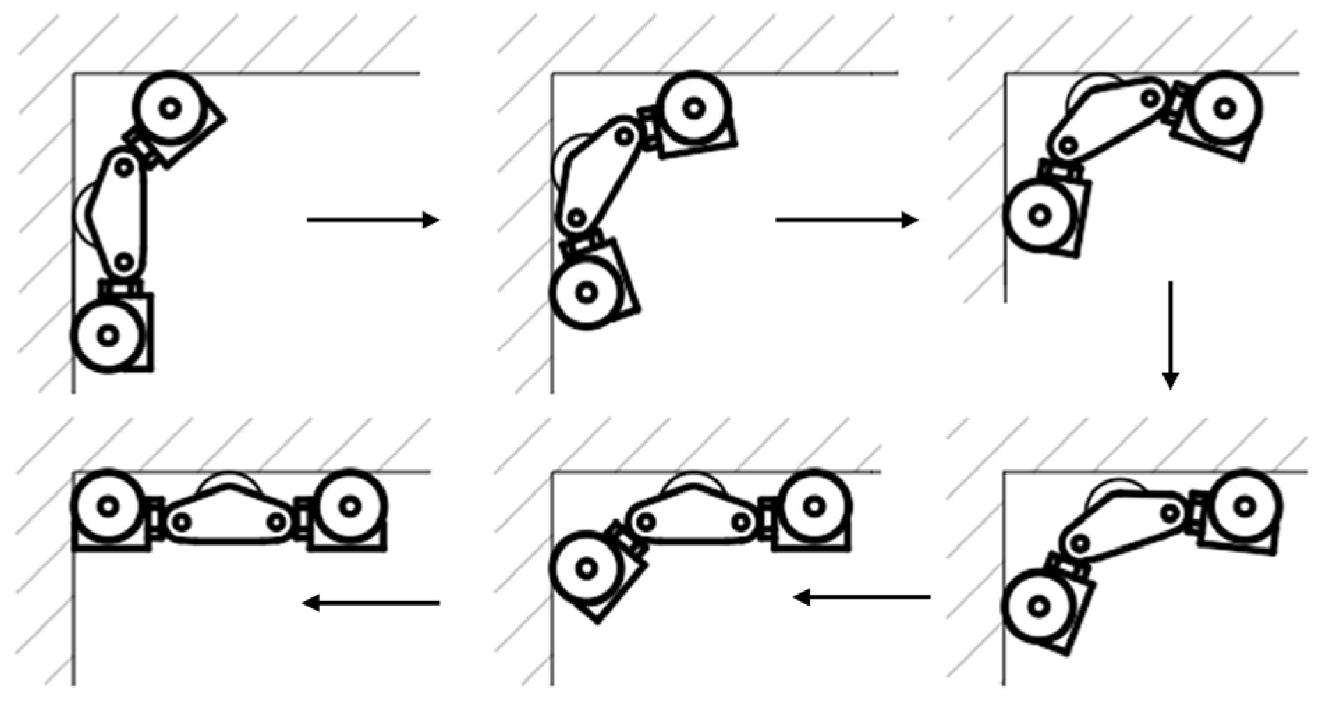
In this section, we will analyze the entire process from before the front wheels of the five-wheel wall-climbing robot touch the ceiling to the full adsorption to the ceiling. The process is shown in Figure 11.
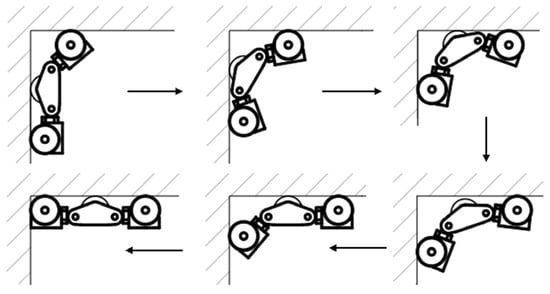
Figure 11.
Diagram of transition from vertical wall to ceiling.
At the beginning of the transition of the front wheels to the ceiling, the suction of the vertical wall decreases sharply, and the suction of the ceiling to the wheels gradually increases. Let the suction force of a single wheel in the horizontal direction be Fx, and the suction force of a single wheel in the vertical direction be Fy, then it is necessary to meet the:
FX2 is the magnetic attraction of the wheel at the moment of transition, and its size changes from moment to moment. Maxwell’s magnetic simulation results from different angles show that Fx2 increases from 1994 N to 506.73 N and Fy rises from 1.2 N to 101.4 N when the magnetic simulation results are changed from 0 to 38 degrees. At 40 degrees, Fy is 133.12 N, so it can be seen that 0~38° and 40~90° are absolutely safe processes. The range angle of the most likely danger is 38~40°, and the known simulation data are substituted, and the five-wheeled wall-climbing robot can still maintain safe working conditions under this angle.
After the front wheel is completely adsorbed to the ceiling, the middle wheel has a suspension process in the span to ensure that the robot does not fall. The conditions are:
Based on the known magnetic attraction, this process does not cause failure such as the robot falling.
3.2. Robot Dynamics Analysis
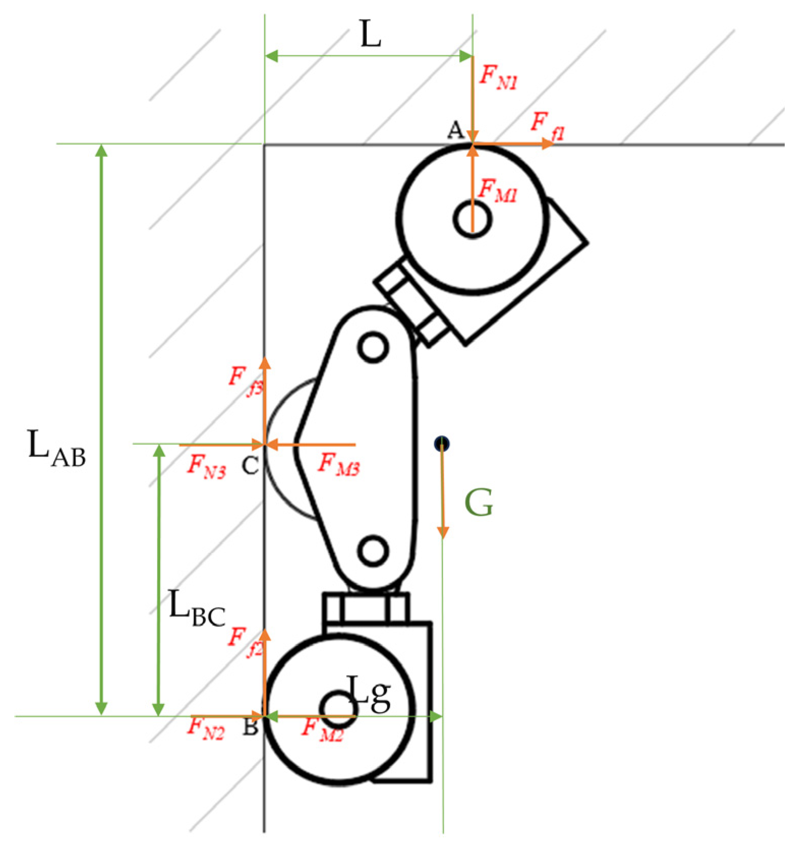
The robot spanning from the vertical wall to the ceiling is one of the most dangerous stages. In the spanning stage, the middle wheel gradually moves away from the wall, the speed is small, the acceleration can be ignored, and the resultant moment is calculated at the rear wheel B point, wherein the wall support force FN3 for the intermediate wheel is 0 (see Figure 12), then it should be satisfied:
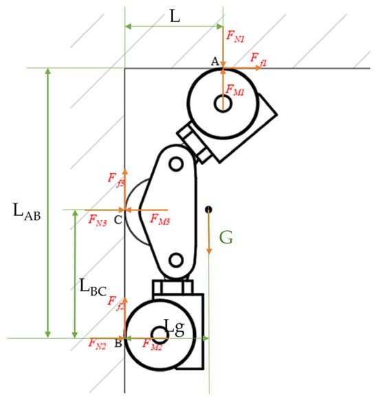
Figure 12.
Force diagram of crossing the critical point.
Fd1 and Ff1 are the driving force and friction force of the front wheel, respectively, and FM1, FM2, and FM3 are the magnetic attraction force of the front wheel, the rear wheel, and the middle wheel on the wall, respectively. FN1 and FN2 are the normal support forces of the front and rear wheels, respectively. L and LBA are the projection distances of the contact point between the front wheel and the wall surface and point B in the X and Y directions, respectively; LBC is the vertical distance between the rear wheels in the robot; Lg is the projection of the center of gravity of the robot and point B in the Y direction. In the process of moving the intermediate wheel away from the wall, the magnetic attraction of the wall to the intermediate wheel is also gradually decreasing.
4. Climbing Robot Prototype Testing
Prototype testing takes place in a lab environment and is designed to simulate real-world conditions encountered by wall-climbing robots in industrial applications. Test surfaces include vertical steel walls, slopes, and curved surfaces to replicate a variety of operating environments. The robot is equipped with sensors to measure adhesion, speed, and stability. There is also anti-falling rope protection; even when the adsorption force is insufficient, there will be no safety accidents.
The experimental setup involved the following key tests: The adsorption force of the robot as it moves in horizontal, 60° inclined, and vertical planes was measured and recorded using a force transducer to verify the effectiveness of the suspended magnetron adsorption module. Obstacle crossing test: The robot was tested on a cuboid obstacle with a height of 12 cm to evaluate the obstacle crossing performance of the five-wheeled wall-climbing robot. The process is that the magnetic chuck of the front wheel is staggered with the wall surface at first, forming an angle so that the magnetic attraction of the front wheel and the wall surface is reduced so that the front wheel is more convenient to lift and cross the obstacle, and then the middle wheel and the rear wheel cross the obstacle in turn. The obstacle-crossing process is shown in Figure 13.
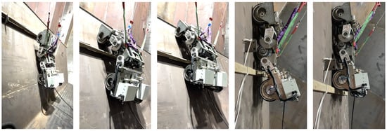
Figure 13.
Robot obstacle-crossing process diagram.
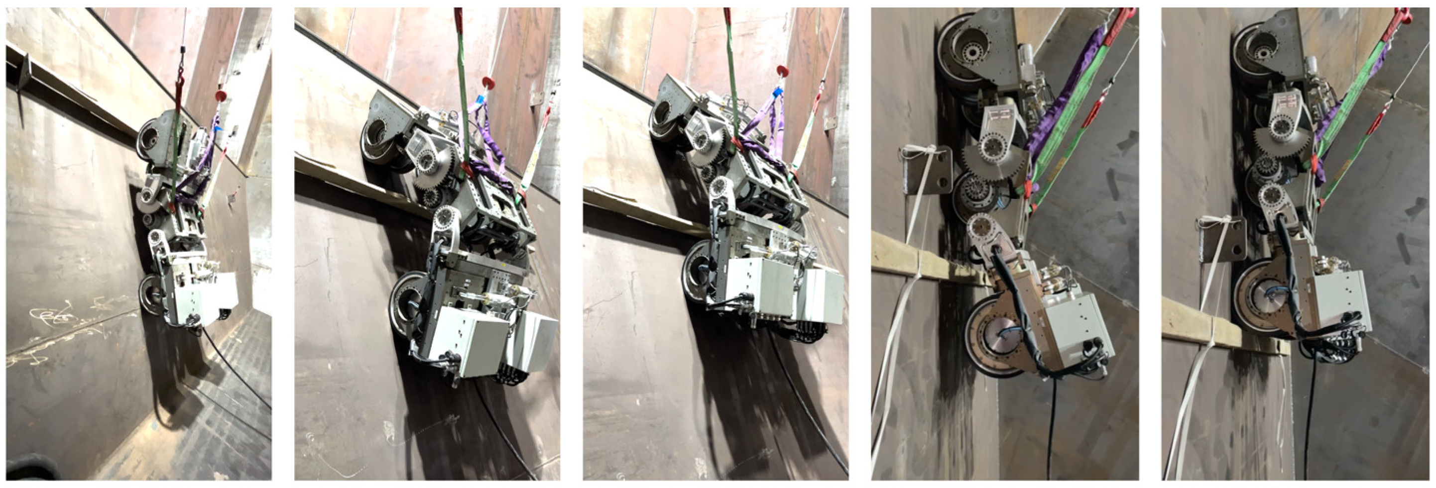
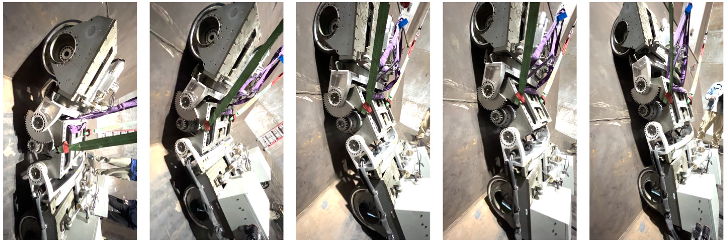
Wall Transition Test: Validates the robot’s ability to transition from horizontal to vertical and from vertical to horizontal. The process of transition from the horizontal plane to the vertical plane is that the front wheel is lifted first and then adsorbed to the vertical wall, and the wall transition is gradually completed and the experimental process of inner and outer fold angles is shown in Figure 14 and Figure 15.
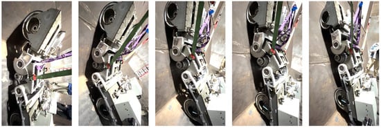
Figure 14.
Diagram of the robot’s inner folding angle transition.
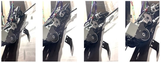
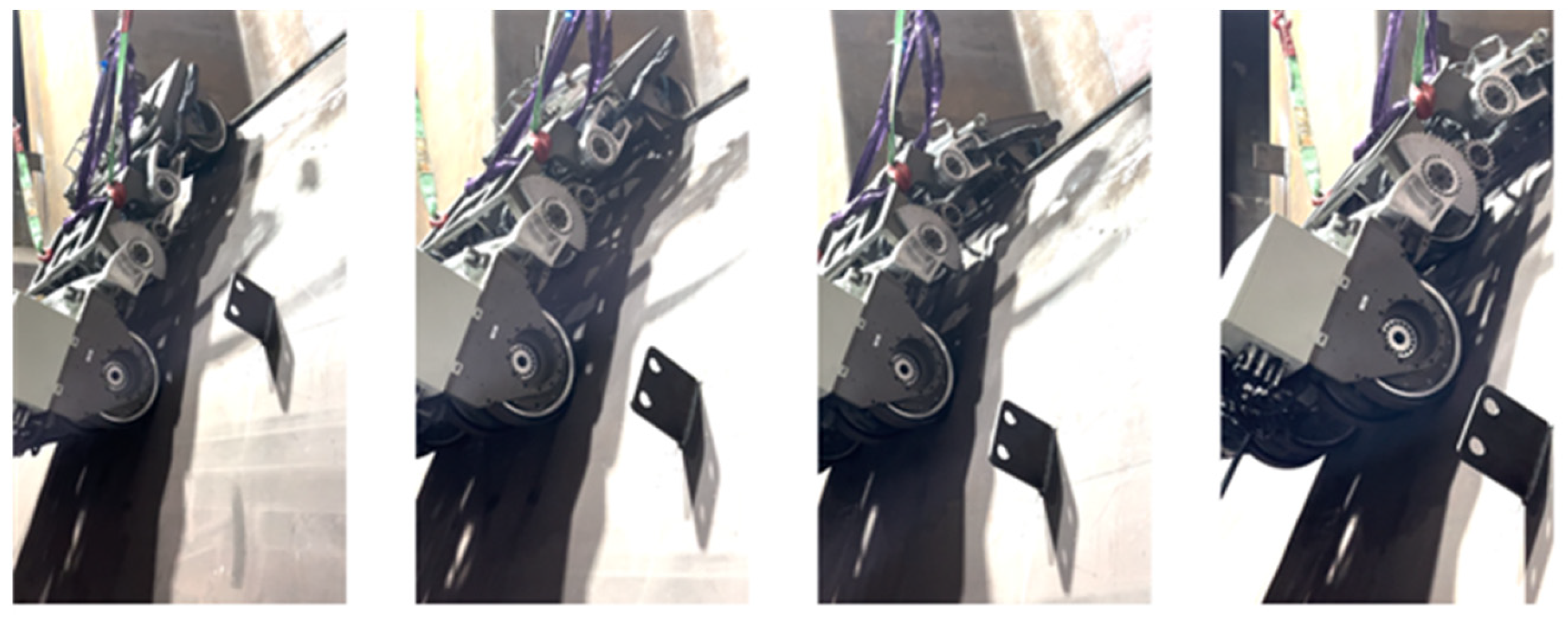
Figure 15.
Diagram of the robot’s outer folding angle transition.
Obstacle crossing tests have shown that the robot can successfully cross obstacles up to 12 cm without losing any stability or adhesion. During the wall transition test, when the robot transitions from a vertical surface to a horizontal surface, the front wheel gradually moves away from the wall, the adsorption decreases, and then the front wheel adsorbs to the horizontal plane, the whole process force changes within a certain range, but the overall force remains within a safe operating range without slipping or falling.
5. Conclusions
This paper designed and developed a prototype of a wheeled magnetic climbing robot, conducted simulation analysis using Maxwell, and explored the effects of the gap and angle between the magnet and the wall on the magnetic attraction, validating its adhesion performance based on the mechanical model and ensuring a safe transition at the critical turning point. Motion tests on metal surfaces demonstrated that the five-wheel climbing robot meets the design requirements. Further research on the prototype’s dynamic and operational performance will focus on validating its performance and reliability in application areas such as industrial inspection, ship cleaning, and building maintenance.
In summary, the analysis and validation of the permanent magnet adhesion performance of the climbing robot were successfully conducted, and the development of the five-wheel climbing robot prototype was completed. This research achievement has significant implications for advancing robot technology applications in engineering and other fields and provides a useful reference and model for related research.
Author Contributions
Conceptualization, P.L. and H.J.; methodology, Z.W.; software, H.J.; validation, P.L., H.J. and Z.W.; formal analysis, H.J.; writing—original draft preparation, H.J.; writing—review and editing, H.J. and P.L.; supervision, P.L.; project administration, Z.W. All authors have read and agreed to the published version of the manuscript.
Funding
This work was supported by Shanghai Jiao Tong University and Leader Harmonious Drive Systems Co., Ltd. Robot and CNC Technology Research and Development Center.
Data Availability Statement
The data that support the findings of this study are available on request from the corresponding author.
Conflicts of Interest
The authors declare no conflicts of interest.
References
- Zheng, K.; Hu, Y.; Wu, B. Trajectory planning of multi-degree-of-freedom robot with coupling effect. J. Mech. Sci. Technol. 2019, 33, 413–421. [Google Scholar] [CrossRef]
- Albitar, H.; Dandan, K.; Ananiev, A.; Kalaykov, I. Underwater robotics: Surface cleaning technics, adhesion and locomotion systems. Int. J. Adv. Robot. Syst. 2016, 13, 7–18. [Google Scholar] [CrossRef]
- Zhou, J. Research on Design and Control Method of Rolling Adsorption Wall-Climbing Robot; Science and Technology of China: Hefei, China, 2023. [Google Scholar] [CrossRef]
- Lee, G.; Wu, G.; Kim, J.; Seo, T.W. High-payload climbing and transitioning by compliant locomotion with magnetic adhesion. Robot. Auton. Syst. 2012, 60, 1308–1316. [Google Scholar] [CrossRef]
- Meng, X.Y.; Dong, H.L. Research on the structure design of climbing robot and the key technology of surface magnetic force absorption. Manuf. Autom. 2018, 40, 19–22. [Google Scholar]
- Bisht, R.; Pathak, P.; Panigrahi, S. Modelling, simulation and experimental validation of wheel and arm locomotion based wall-climbing robot. Robotica 2023, 41, 433–469. [Google Scholar] [CrossRef]
- An, L.; Zhang, C.; Chu, S.; Zhang, J.; Yang, Y.; Liu, J.; Li, S.; Liu, J.; Wang, Z. Finite element analysis of permanent magnet attraction device based on Halbach array wall-climbing robot. Mech. Res. Appl. 2020, 33, 36–39. [Google Scholar]
- Dian, S.; Fang, H.; Zhao, T.; Wu, Q.; Hu, Y.; Guo, R.; Li, S. Modeling and trajectory tracking control for magnetic wheeled mobile robots based on improved dual-heuristic dynamic programming. IEEE Trans. Ind. Inform. 2021, 17, 1470–1482. [Google Scholar] [CrossRef]
- Zhang, Y. Structural Design and Motion Performance Analysis of Permanent Magnet Adsorption Wall-Climbing Robot; Chang’an University: Xi’an, China, 2023. [Google Scholar]
- Sun, Z. Research on Structural Design and Control System of Underwater Hull Defouling Robot; Dalian University of Technology: Dalian, China, 2022. [Google Scholar] [CrossRef]
- Chen, L. Research on Obstacle Crossing and Wall Transition of Permanent Magnet Adsorption Wall-Climbing Robot; China Jiliang University: Hangzhou, China, 2018. [Google Scholar]
- Song, W.; Jiang, H.; Wang, T. Optimal design and experimental study of magnetic adsorption components for wall-climbing robots. J. ZheJiang Univ. 2018, 52, 6–13. [Google Scholar]
- Chen, Y. Theoretical Analysis and Experimental Study of Magnetic Adsorption Unit of Halbach Array Robot; Nanjing University of Science and Technology: Nanjing, China, 2013. [Google Scholar]
- Yang, B. Design of Mechanical System of Wall-Spanning Magnetic Adsorption Wall-Climbing Robot and Analysis of Mechanical Characteristics under Typical Working Conditions; Southeast University: Dhaka, Bangladesh, 2015. [Google Scholar]
- Zhang, D.; Yang, P.; Huang, Z.; Sun, L.; Zhang, M. Design and optimization of pendulum magnetic adsorption mechanism for wall-climbing robot. Chin. J. Eng. Des. 2023, 30, 334–341. [Google Scholar]
- Zhang, X. Research on Wheeled Suspended Magnetic Adsorption Wall-Climbing Robot (Applied Research).Heilongjiang; Harbin Institute of Technology: Harbin, China, 2012. [Google Scholar] [CrossRef]

Disclaimer/Publisher’s Note: The statements, opinions and data contained in all publications are solely those of the individual author(s) and contributor(s) and not of MDPI and/or the editor(s). MDPI and/or the editor(s) disclaim responsibility for any injury to people or property resulting from any ideas, methods, instructions or products referred to in the content. |
© 2024 by the authors. Licensee MDPI, Basel, Switzerland. This article is an open access article distributed under the terms and conditions of the Creative Commons Attribution (CC BY) license (https://creativecommons.org/licenses/by/4.0/).