Article

Design and Analysis of a Robotic Gripper Mechanism for Fruit Picking

1
School of Mechanical Engineering, Jiangsu University of Science and Technology, Zhenjiang 212100, China
2
School of Information Engineering, Jiangxi University of Science and Technology, Ganzhou 341000, China
*
Author to whom correspondence should be addressed.
Actuators 2024, 13(9), 338; https://doi.org/10.3390/act13090338
Submission received: 2 August 2024 / Revised: 23 August 2024 / Accepted: 2 September 2024 / Published: 3 September 2024
(This article belongs to the Special Issue Design and Control of Agricultural Robotics)

Abstract

:
A gripper is the critical component of the robot end effector for the automatic harvesting of fruit, which determines whether the fruit can be harvested intact or undamaged. In this paper, a robotic gripper mechanism based on three-finger and variable-angle design is designed and analyzed for spherical or cylindrical fruit picking. Among the three fingers of the mechanical gripper, two fingers are rotatable through a pair of synchronous gears to ensure enough contact area for the grasping surfaces, which adapt to fruits of different sizes, such as cherry, loquat, zucchini, and so on. Furthermore, the mathematical relationship between gripper driving force and finger gripping force is obtained by the kinematic analysis of the gripper to realize stable grasping, and a grasping index is employed for the structural parameter optimization of our gripper. The grasping motion is analyzed, and the kinematic simulations are carried out, when the driving speeds of the gripper are 5 mm/s, 10 mm/s, and 15 mm/s, respectively. The system transfer function related to driving speed is obtained by curve fitting. Then, the grasping experiments are conducted with various spherical and cylindrical fruit, of which the weights are between 8 and 300 g and the diameters are from 9 to 122 mm. The experimental results demonstrate that our gripper has good kinematic performance and fruit adaptability. At the same time, the grasping is stable and reliable while no obvious damage appears on the fruit surface.

1. Introduction

In recent decades, robot technology has developed rapidly in agriculture, manufacturing, healthcare, aerospace and other fields, since labor costs have increased [1,2,3,4]. Dangerous and repetitive tasks have been gradually replaced by various robots [5]. As early as the 1980s, Schertz and Brown proposed the use of mechanical fruit and vegetable harvesting methods [6], and this study is recognized as the beginning of agricultural picking robot research. The labor-intensive and time-consuming characteristics of agricultural product harvesting make robotic picking with cost reduction and high efficiency have great potential for future development [7,8,9]. Generally speaking, an agricultural robot comprises a mobile platform and various actuators including robotic end effectors, collaborative sensors and other auxiliary structures, in which the end effector is key for non-destructive fruit harvesting [6,10,11].
The end effector is a critical component of a robot required to complete final execution requirements. Different application fields and working conditions have different requirements. Thus, an end effector is always designed for specific task objectives in different working scenarios [12]. In recent years, intelligent technologies of agricultural robots have developed rapidly for harvesting fruits such as strawberries, apples, oranges, tomatoes, etc. Great progress has been made in the structural design scheme and function expansion of robots, including fingers, vacuum cleaners, suction nozzles, scissors and end effectors [13,14]. In the field of fruit harvesting, end effectors are classified into two types according to harvesting methods: direct separation and flexible grasping [11]. Direct separation includes cutting fruit stems and shaking fruit trees, which is not suitable for the fruit’s biological quality requirements. Flexible grasping mainly includes suction and clamping methods [15]. In the suction type, the geometric characteristics of the fruit should be abstracted to design trumpet-shaped suckers of appropriate size. Then, harvesting is completed by forming negative pressure close to the target fruit with different auxiliary actions. However, this method has certain limitations for harvesting fruits with large differences in size and shape [16].
The gripping–grasping method effectively realizes fruit harvesting with specially designed grippers, of which the finger numbers are two, three, and more [12,13,17]. Ref. [18] used a bionic surface and two fingers to grip the fruit or its stem and then completed the fruit harvesting with other auxiliary actions. The end effector based on fingers directly grasps fruit with the help of a vacuum chuck, finger shear and other auxiliary actions; thus, the complex spatial model is balanced [6,12,19,20,21].
The gripper with two fingers needs great contact force and poor versatility and is not suitable for fruit protection and harvest [6]. Four or more fingers have obvious limitations, such as the fact that the control is more complex and the maintenance is inconvenient [22,23]. There is a problem of a small contact area or high complexity in coordinating and adjusting grasping. The contact area between the finger and the fruit is an important indicator for non-destructive grasping. In addition to self-centering for grasping spherical fruit, three-finger grasping also has less restriction on the grasping positions of long columns and strips, making it easier to achieve balance under the same grasping force. It is also the most commonly used and stable grasping actuator. The contact area can be adjusted by simply grasping the position or rotating the finger angle [17,24], ensuring the size of the contact area and making it easier to successfully grasp.
Apart from the contact area of the gripper and fruit, the grasping force is an important index of fruit harvest. Adjusting to the appropriate gripping force improves the stability of fruit gripping. However, excessive overshoot makes it easier to cause fruit surface damage, while a long adjustment time reduces the picking efficiency sharply, which does not meet the fruit harvesting requirement. One of the solutions is upgrading the control system, including hardware and software. Wei Ji et al. proposed an adaptive impedance control strategy for apple harvesting to adapt robotic grasping, which improved the grasping overshoot and adjustment time [25]. Torielli et al. used ROS End-Effector software modules to shield the physical hardware differences of the end effector to achieve grasping control. By studying the grasping parameters, the problem of crushing fruit during grasping was solved [26].
To solve the problems of contact area and grasping force during fruit harvesting, a robotic gripper is proposed based on the three-finger and rotation mechanism in this paper. The gripper employs a fixed finger and two rotating fingers, which ensure enough contact area. The relation of driving force and grasping force is conducted to achieve stable gripping, and a grasping index is adopted to optimize the structural parameters of the proposed gripper.
The organizational structure of this paper is as follows. In Section 2, we present the design scheme and working principle of our gripper. The calculation and simulation of grasping motion are carried out in Section 3. Then, Section 4 shows the experimental results. Finally, the conclusions and future work are outlined in Section 5.

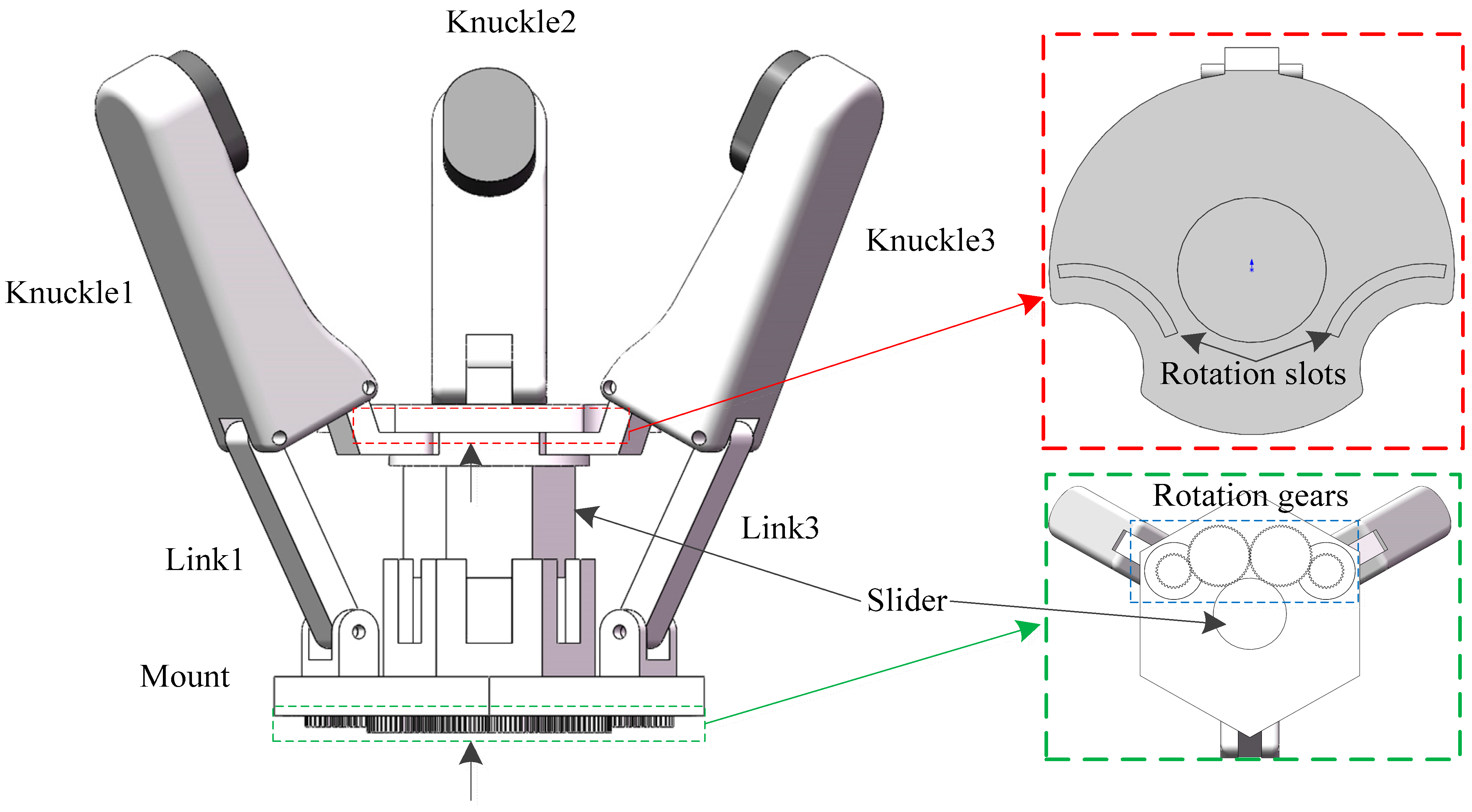
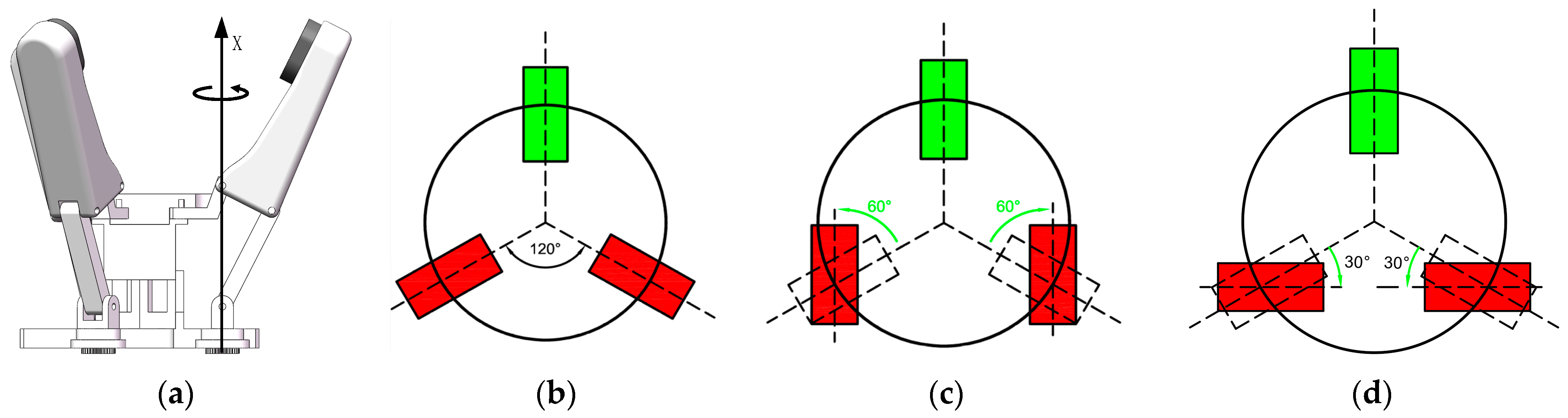
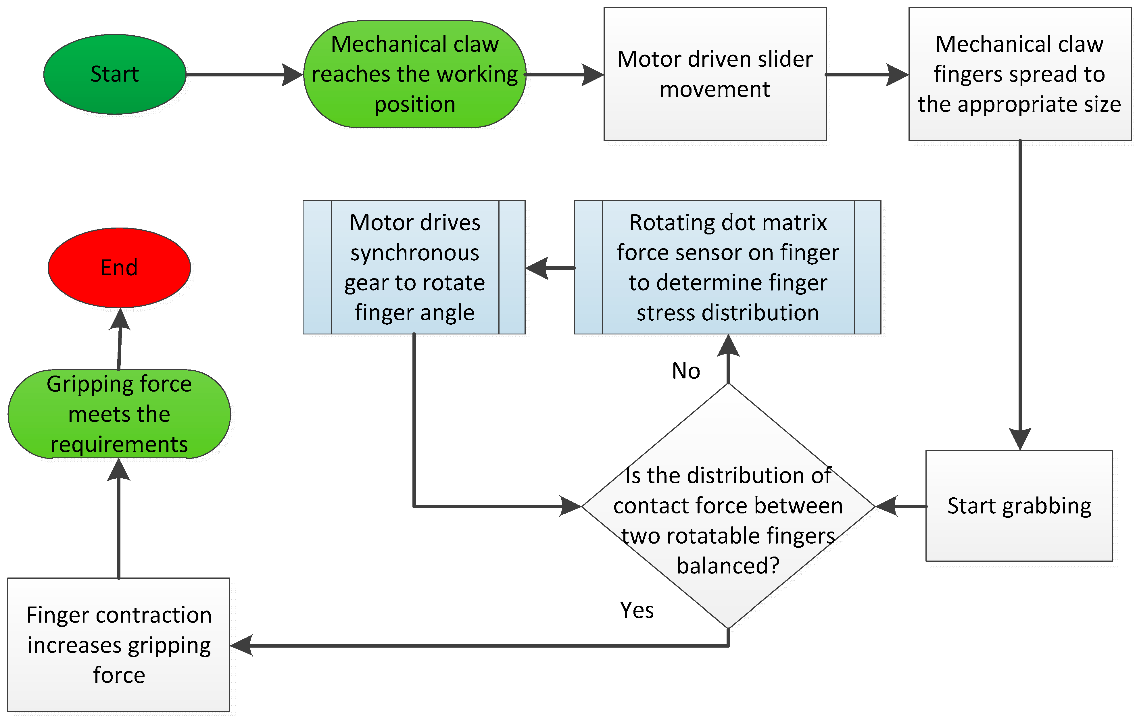
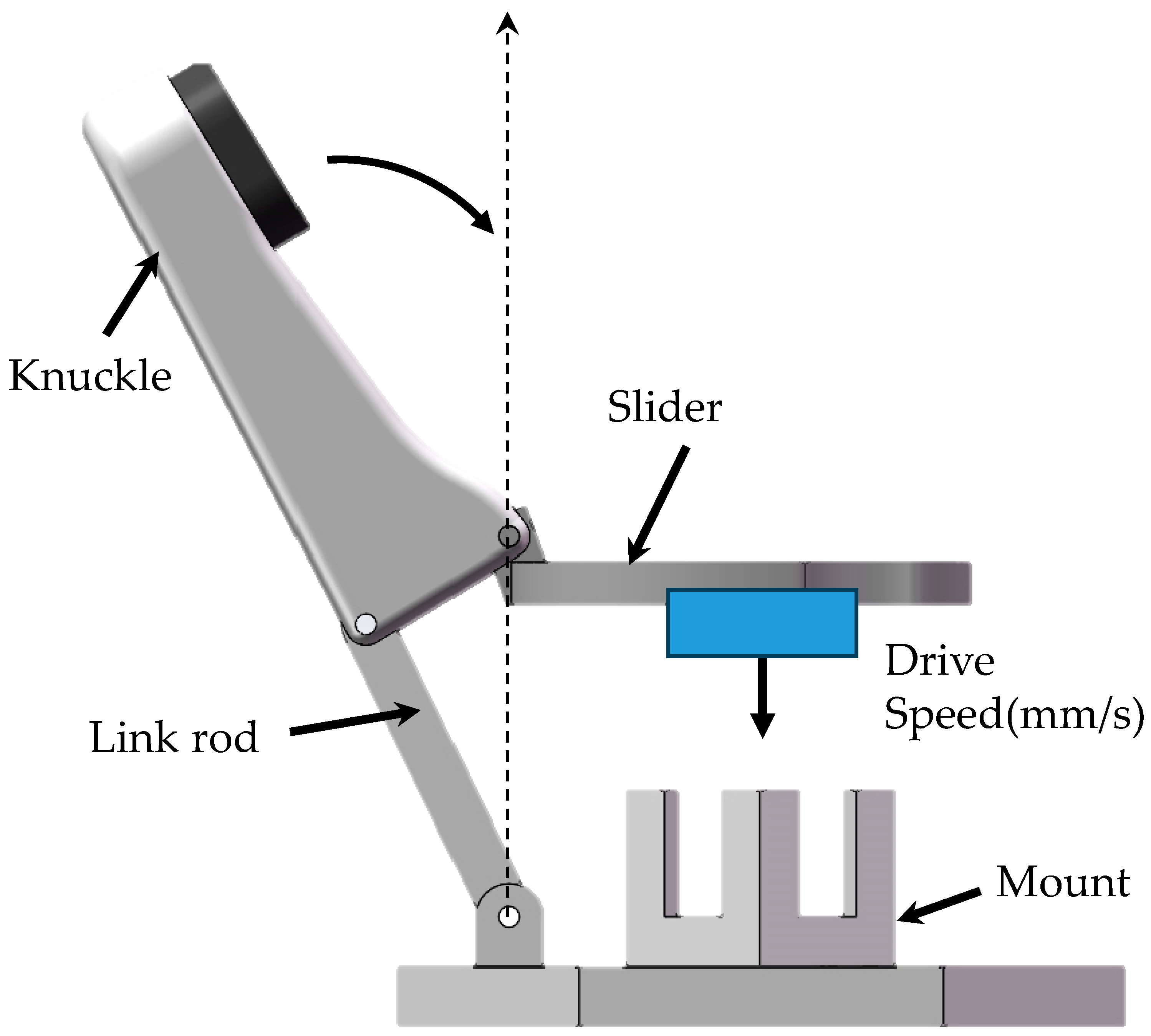
2. Design Scheme and Working Principle

The proposed robotic gripper consists of three parts: working fingers, a driving block, and a support frame. Working fingers are mainly used to implement grasping actions. The driving block is the mechanism that drives the grasping motions. In addition to supporting and connecting all parts of the gripper, the support frame mainly realizes the synchronous rotation function of two rotatable fingers around a fixed finger.
The gripper, as shown in Figure 1, has three working fingers that consist of knuckles and links. The knuckles come into direct contact with the fruit surface during the grasping process. The innerside of the three knuckles is connected to the slider, and the outerside of the three knuckles is fixedly connected to the support frame through the links, controlling the angle of finger rotation and motion. In the view along the direction of the arrow at the slider in Figure 1. The driving block consists of a main slider and connecting components with other parts. The slider is equipped with rotation slots to ensure that two rotatable fingers rotate around the fixed finger. The support frame includes a mount and four rotation gears. Rotating gears are divided into driving gears in the middle and synchronous rotational gears on both sides. The slider is matched with the hexagonal groove on the mount to prevent the gripping structure from changing due to rotation during the slider movement. The slider is driven up and down by a ball screw pair to open and close the fingers. The link of the working finger is synchronized with the rotating gear to drive the rotation of the finger, achieving shape adaptation and stable grip.
Adding a degree of freedom to a finger can improve clamping compatibility. One of the driving gears is rotatably connected to the motor to drive the working finger rotation. The other driving gear is meshed to adjust the steering direction, so that the two fingers rotate the same angle symmetrically and simultaneously around the fixed axis as shown in Figure 2a. In Figure 2b, the green area represents a fixed non rotatable finger. The two rotatable fingers of the proposed gripper are the red rectangles in Figure 2b, which rotate around a fixed axis to ensure the contact area of the fingers and fruit during the grasping process. Two fingers synchronously rotate in the positive or negative directions at the same angle, achieving structural adaptability to different shapes and sizes of fruit, as well as their respective irregular fruit surfaces. The angle between that normal state is 120°, as shown in Figure 2b, and the rotation range is 90°, while the rotation limit state is counterclockwise 60° in Figure 2c and clockwise 30° in Figure 2d.
Figure 3 shows the working principle and grasping process of the robotic gripper. The grasping actions are achieved by the motor driving the slider up and down through a ball screw pair to open and close the fingers. We determined the contact state between the finger and the fruit surface through dot matrix force sensors on the rotatable fingers. Using the force distribution on the sensor as a judgment signal to control the direction of finger rotation, we ensured that the gripping contact area was sufficiently large. We obtained the maximum contact force with fruits while minimizing the gripping force of the robotic gripper. We then continued to contract fingers to increase gripping force and achieve stable gripping requirements, completing the gripping process.
The spatial size of the entire mechanical claw at the limit state is within the range of a cylinder with a diameter of (105, 155) mm and a height of (116, 123) mm. The link length l1 = 39 mm, the knuckle width l2 = 20 mm, the knuckle height h = 70 mm, and the distance between the fixed positions of the three fingers on the moment and the center of the moment r = 30 mm. Compared to four fingers, three fingers require fewer coordinated fingers to grasp elongated shapes, making adjustment relatively simple. In some rotatable biomimetic three-finger mechanical claws, the surfaces of two rotating fingers rotate around the positions of their respective driving motors. For example, Barrett Technology’s BarrettHand from Newton, Massachusetts, USA. This makes the fingers face their respective rotation centers. The design presented in this paper directly fixes three fingers at a 120° angle around the center of the circle, so that the three fingers can evenly bear the load when grasping. In contrast, the two rotating fingers only rotate around the normal axis of the fixed base, which can maintain surface contact with the fingers all the time. According to this scheme, the problem of three fingers not being able to make each finger touch the fruit peel and increase pressure is solved effectively.

3. Calculation and Simulation

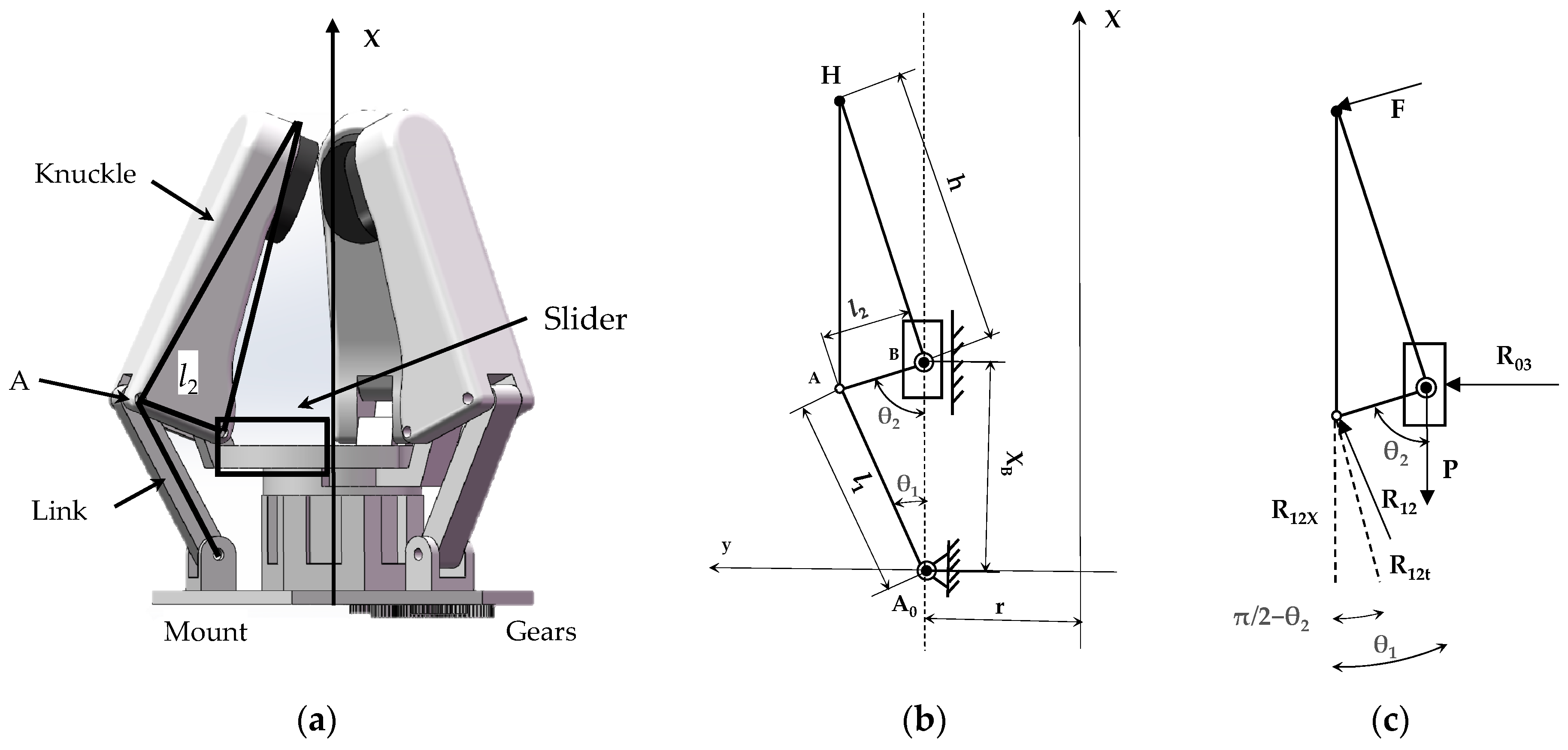
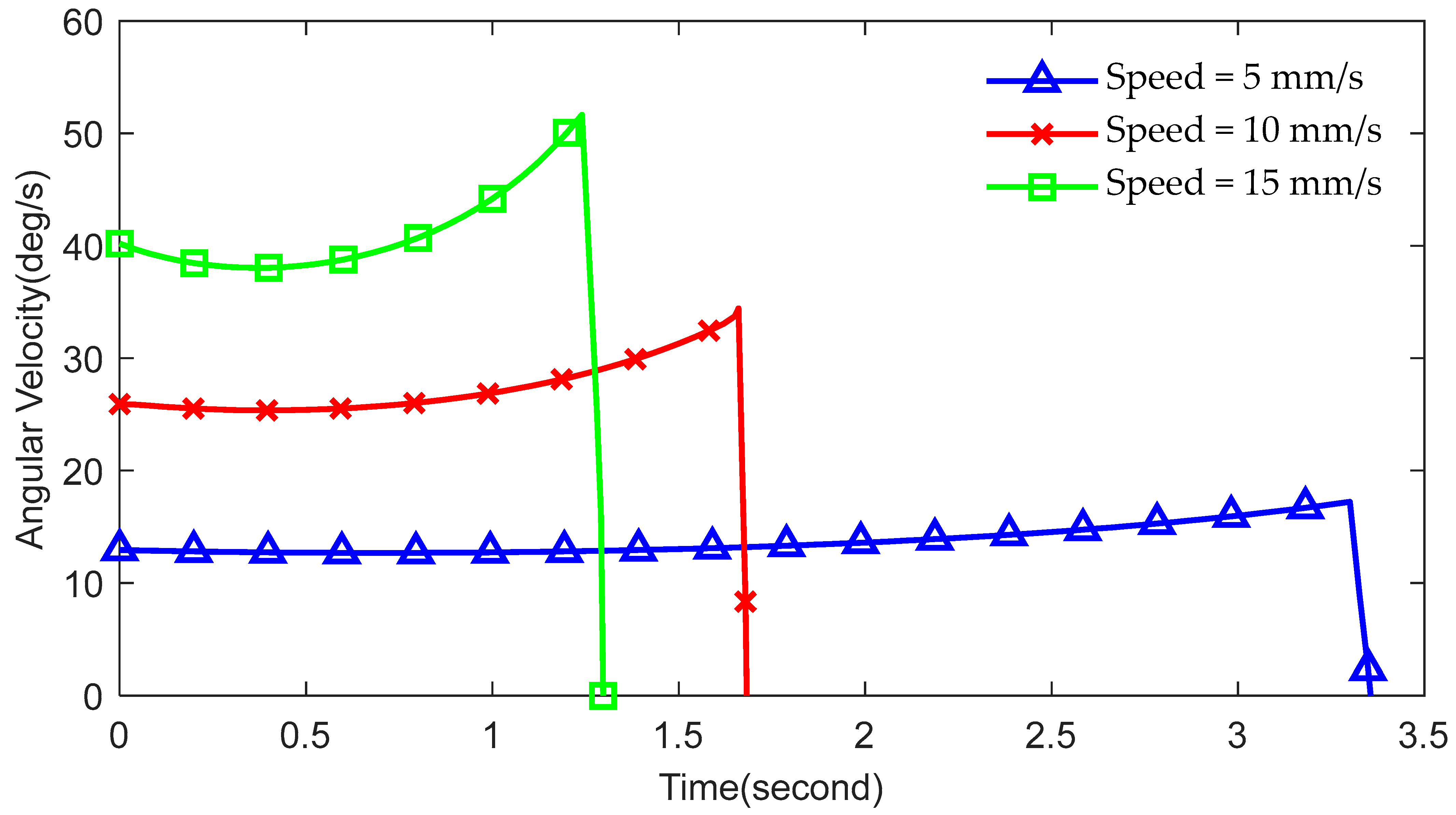
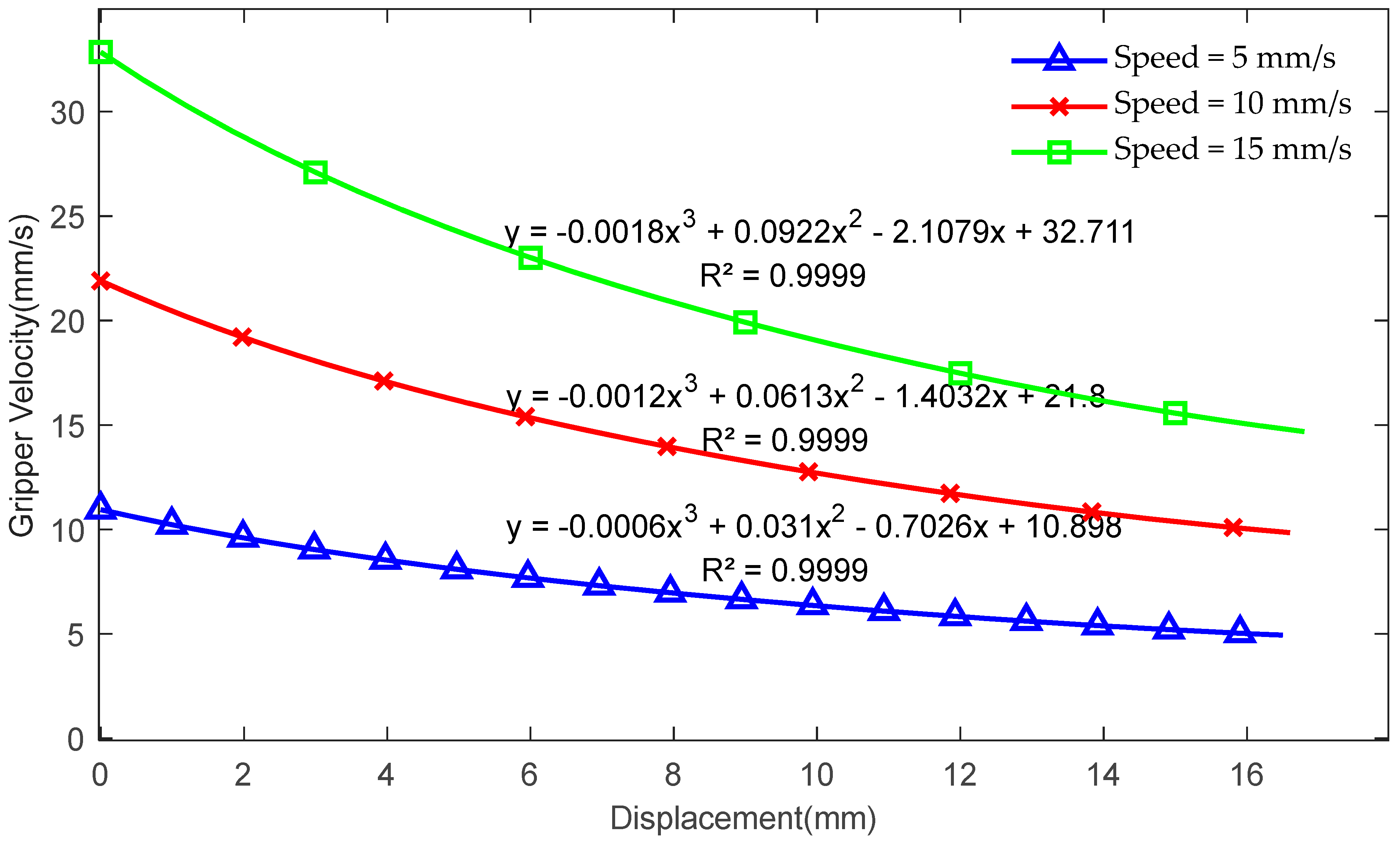
3.1. Motion Analysis

For fruit grabbing, there are mainly near-spherical items such as apples, oranges, nectarines, tomatoes, pears, etc. Small, nearly spherical fruits such as strawberries can be grasped approximately by adjusting the grasping angle. The same is true for long columnar fruit such as cucumber and eggplant. Its reference size ranges from 20 mm to 120 mm. The minimum range of the fingertips requires them to be able to pick up the smallest-sized fruit without interfering with each other. The robotic gripper is based on the crank–slider mechanism, and its brief structure model is shown in Figure 4a. The X-axis position is the distribution center of the three fingers of the robot gripper, and it is also the sliding coordinate axis at the center position of the slider.

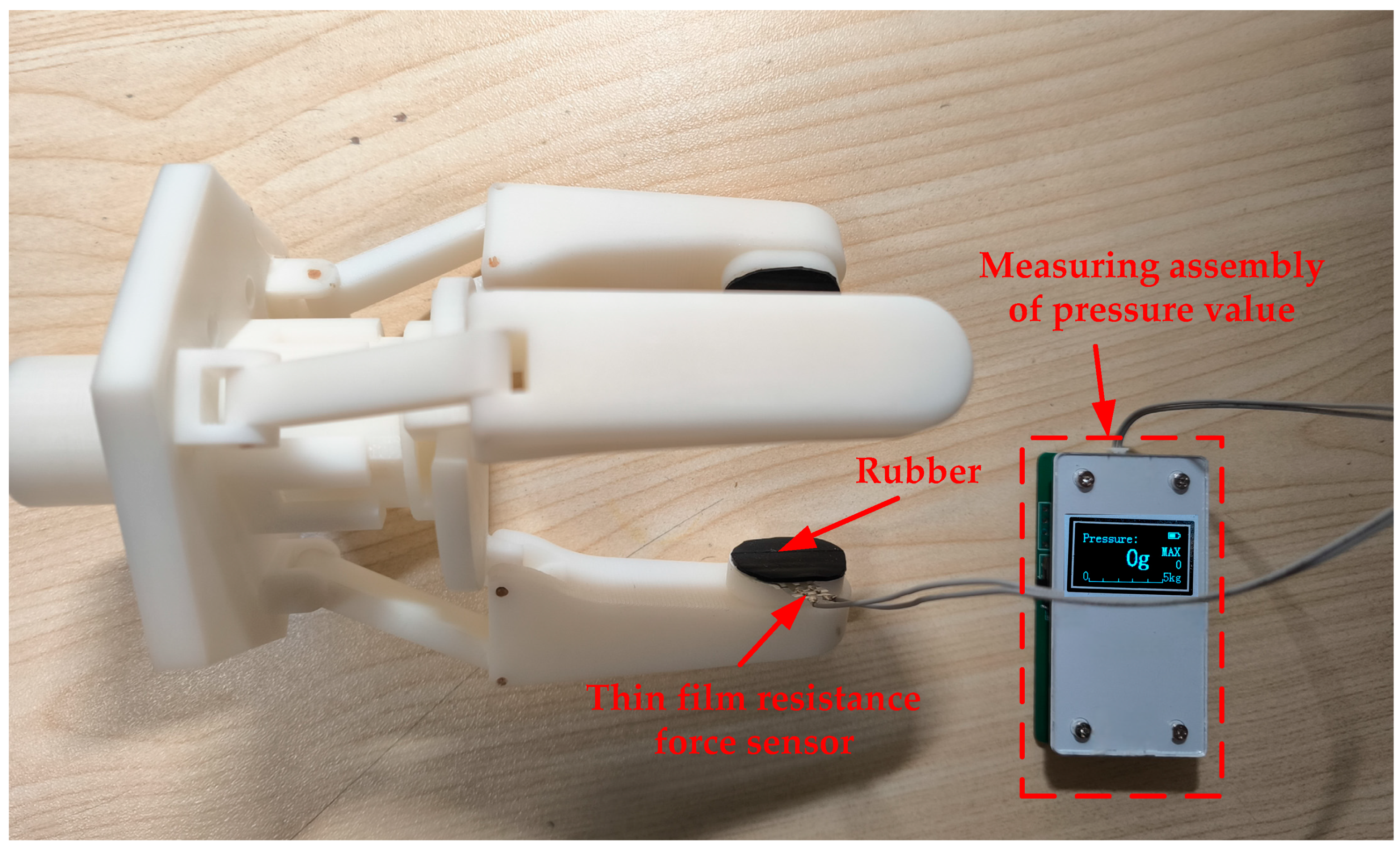
3.2. Grasping Force and Structure Size Calculation

In order to evaluate the performance and efficiency of the clamping mechanism, it is convenient to simulate the manipulator operation motion. Through classical mechanical research methods, kinematics, and static analysis, the proper simulation of the clamping mechanism can be achieved. The grasping index (G.I.) is introduced as an indicator of grab performance [27], and the formula is defined as:
G . I . = F × sin φ P
where the shape and position angle of clamping time is P, which is the driving force applied by the actuator. F is the grab force. Referring to the design parameters shown in Figure 4b,c, the gripper structure has the following kinematic relationship:
l 1 × sin θ 1 = l 2 × sin θ 2
cos θ 1 = X b   2 + l 1   2 l 2   2 2 X b × l 1
where l1 and l2 are the lengths of the two links in the mechanism. The θ 1 and θ 2 are the angles between l1 and l2 and the X-axis direction, respectively. Xb describes the coordinate position parameters of the slider. When the grasping of the target object is in equilibrium, grasping performance can be evaluated by the relationship between the grasping force and driving force. The moment balance at point B in Figure 4b is
F × h R 12 t × l 2 = 0
R 12 x P = 0
where h is the height of the finger, and R12 is along the l1. R12t and R12x are the components of the supporting force of the connecting rod along the vertical direction of the l2 and the X-axis direction. The connecting rod has no other external force and can be regarded as a tensile bar according to the material mechanics. The direction of the internal force is a pair of interactions in the link direction. Moreover, the relationship between them is
R 12 t = R 12 × sin [ π ( θ 1 + θ 2   ) ]
R 12 x = R 12 × cos θ 1
The driving force P expression can be obtained from Equations (1)–(6):
P = F × h × cos θ 1 l 2 × s i n [ π ( θ 1 + θ 2   ) ]
And the expression of the G.I. (grasping index) value can be obtained from the above equation as follows:
i n d e x = l 1 h × tan θ 1 sin [ π ( θ 1 θ 2 ) ]
where the index expresses the G.I. value.
On the one hand, the index of the robotic gripper depends on the height of h the manipulator. However, since the minimum height of the manipulator should exceed half the diameter of the target, it is obviously difficult and unreasonable to increase the index by reducing h. On the other hand, another parameter l1 can be optimized to improve the index value.
There are two specific parameters for the optimization evaluation index, one of which is the indexmean, that, the average of the G.I. The optimization goal is to maximize the G.I., which means maximizing the grasping ability in the process. The formula can be expressed as follows:
max i n d e x m e a n   subject   to   l i   , min < l i < l i   , max   for   i = 1 , 2
Another parameter is to minimize the average deviation of the G.I., which is the value of index changes during the grasping process. It can be expressed as follows:
min i n d e x m a x i n d e x m i n i n d e x m e a n   subject   to   l i   , min < l i < l i   , max   for   i = 1 , 2
The mean deviation of the holder is the ratio of the index change in the grasping process to the indexmean. This indicator reflects the stability of the grasping ability during the grasping process or the stability of the grasping force. The above two indicators can be used to evaluate the performance of a robot finger structure parameter when the grasping ability is maximized and stable during grasping. According to the requirements of grasping the object size, the boundary conditions of the size parameters of each part of the mechanical claw are preliminarily determined, as shown in Table 1.
Finally, two reasonable design schemes are obtained. In scheme 1, l1 and l2 are 30 mm and 20 mm, respectively. The G.I. deviation is 0.541751, and indexmean is 0.286937. In scheme 2, l1 is 39 mm, l2 is 20 mm, the G.I. deviation is 0.400687, and the indexmean is 0.279419.
The result of the indexmean from scheme 1 is better, but the average deviation of the G.I. of scheme 2 is greater, while the average deviation of the G.I. and indexmean of scheme 2 is more reasonable. Therefore, a scheme with a relatively large average and a minimum average deviation of the G.I. is selected. The final mechanical claw structure parameters are l1 = 39 mm and l2 = 20 mm. The X-axis direction that coordinates the motion of the slider in the gripper is [27, 43.5] mm. The maximum motion range is 16.5 mm. As shown in Figure 4b, the motion range of the robotic gripper can be expressed as follows:
r H = r + h s i n ( π 2 θ 2 )
where rH is the diameter of the grabbing object.
The motion range of the robotic gripper and fingers can be obtained by formula analysis. The diameter range of the object fruit is [9.18, 122.06] mm.

3.3. Finite Element Analysis

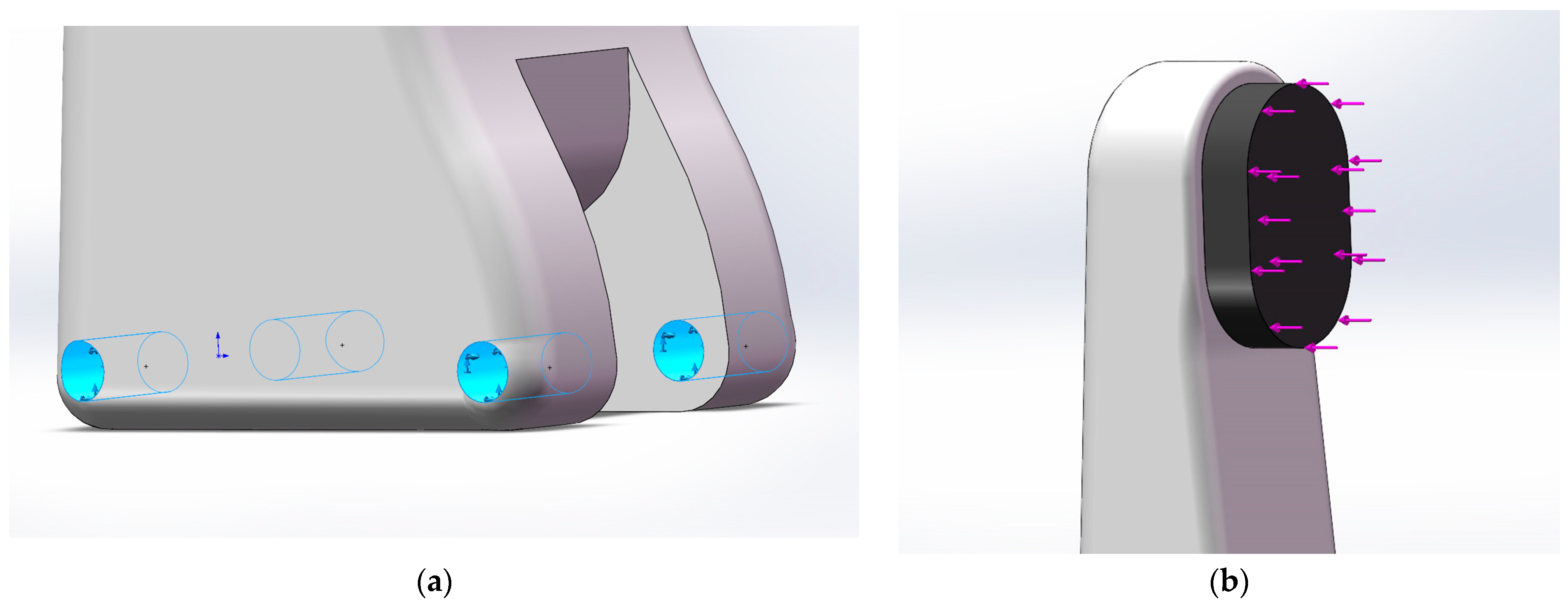
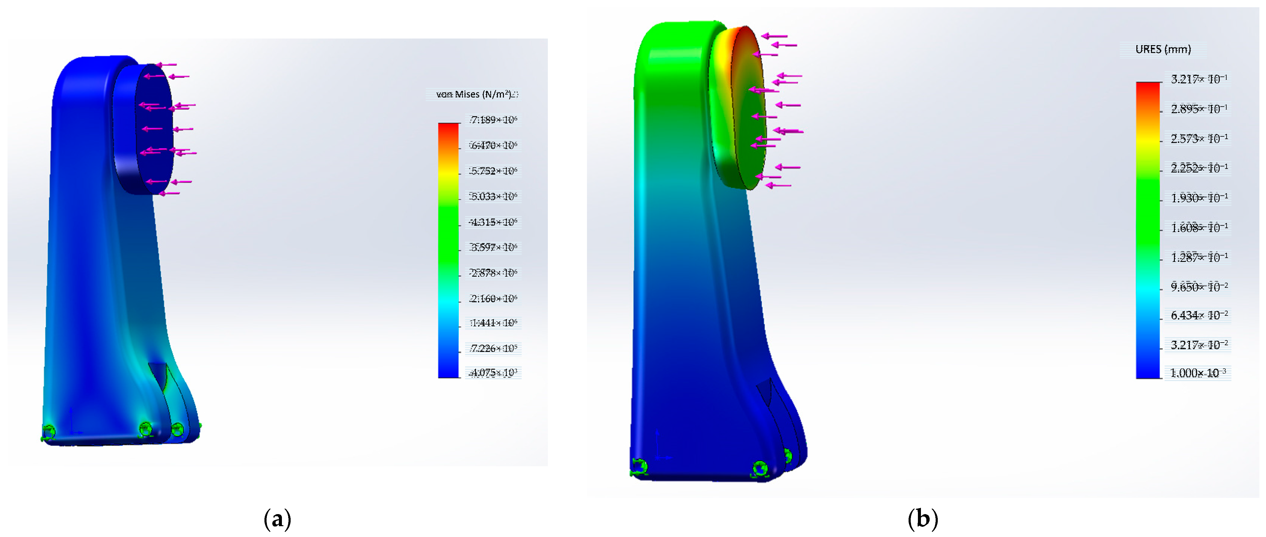
3.3.1. Structural Analysis of Robotic Gripper

The gravity of fruit is mostly in the range [0.5, 2] N. For the convenience of calculation, when the friction coefficient is 0.5, it can be known from Equations (4) and (8) that the loading torque F of one knuckle can be given as 40 N. The finger joint material is ABS engineering plastic. The protrusion on the fingertip shown in Figure 5b is made of rubber and used to protect the fruit when the robotic gripper grasps it. The performance parameters of each material are shown in Table 2.
We add the fixing fixture to the blue position Figure 5a. A 40 N normal uniform load was added to the surface in the direction of the arrow at the position shown in Figure 5b. Triangular mesh elements with side lengths of 0.2 mm and tolerances of 0.01 mm were selected for grid division. Finally, an example of static stress analysis was given.
The stress and displacement results of knuckles obtained through Solidworks 2021 Simulation static stress simulation analysis are shown in Figure 6. It can be seen in Figure 6a that the maximum stress is in the fixed position of the knuckle, and the value is far less than the yield strength of ABS engineering plastic, which is completely suitable for grasping. In the static stress analysis and displacement simulation shown in Figure 6b, the maximum displacement at the fingertip grasping fruit and vegetable convex is 0.322 mm. This displacement change is within a reasonable range for precise grasping, especially for protecting fruit.

3.3.2. Motion Simulation

We used the Solidworks motion plug-in to solve the motion parameters of kinematic simulation. Since the bending motion of the three fingers was the same, we only needed to simulate one finger. When the slider moves downwards, the direction of rotation of the finger joint is indicated by the arrow in the Figure 7. And the connection between the finger joint and the slider moves downwards along the dashed axis. We set the motion speed corresponding to the driving component on the slider, as shown in Figure 7.
Three different driving speeds were selected for the slider: 5 mm/s, 10 mm/s, and 15 mm/s. The kinematic simulation was carried out, and the angular velocity and angular acceleration images under three different driving speeds were drawn on the knuckles.
The angular velocity and angular acceleration of the knuckle obtained through Solidworks 2021 motion simulation are shown in Figure 8. It can be seen that within the limited range of motion of the three-finger robotic gripper, although the total grasping motion time increases by 2–3 times at a driving speed of 5 mm/s, which will greatly affect the efficiency, the angular velocity of the motion changes more smoothly. At higher drive speeds of 10 mm/s and 15 mm/s, the knuckle response speed is doubled, but the instability of the angular velocity change during the motion also continues to increase with the increase in driving speed. For precise position control, it is more difficult and requires higher precision for transmission components. Therefore, the driving speed of about 5 mm/s is more suitable for lossless grasping. At a driving speed of 5 mm/s, the angular acceleration response is more stable, which is conducive to the control of the grasping force and reduces damage to the fruit. The movement of the parts not related to direct grabbing can be completed at a higher driving speed, and the grabbing part can be completed at a stable low driving speed, which improves efficiency while protecting the fruit from damage.
In Figure 9, angular acceleration decreases to zero at first and then increases at different driving speeds. Corresponding to the horizontal position of the curve in Figure 8, the attenuation to zero occurs at the same motion position, i.e., when the knuckle angle is perpendicular to the driving block. From Figure 9, it can be seen that the fluctuation in the angular acceleration also increases with the increase in the driving speed, and the grasping speed changes more greatly at high speed, which is not suitable for direct grasping.
In Figure 8 and Figure 9, it can be seen that for the first half and second half of the movement, the response of the fingers to the driving input is high, and the response characteristics are changing, which requires a higher response for the grasping control and feedback adjustment of the system, which is not conducive to safe grasping.
The transfer characteristic of the system is an inherent characteristic independent of the input quantity. Under different driving speeds shown in Figure 10, the grasping response speed of the robotic gripper at the corresponding displacement is a variable varying with the input driving speed, and it conforms to a linear relationship.
By carrying out the curve fitting of the gripper speed and displacement of the driving slider, the system transfer function related to driving speed was obtained, namely the transfer function between the driving system and the gripper system.
V g r i p p e r _ o u t = V D r i v e _ i n ( 0.00012 x 3 + 0.0062 x 2 0.14052 x + 2.1796 )
where Vgripper_out is the grasping speed of the proposed gripper, Vdriver_in is the input driving speed, and x is the displacement of the slider.

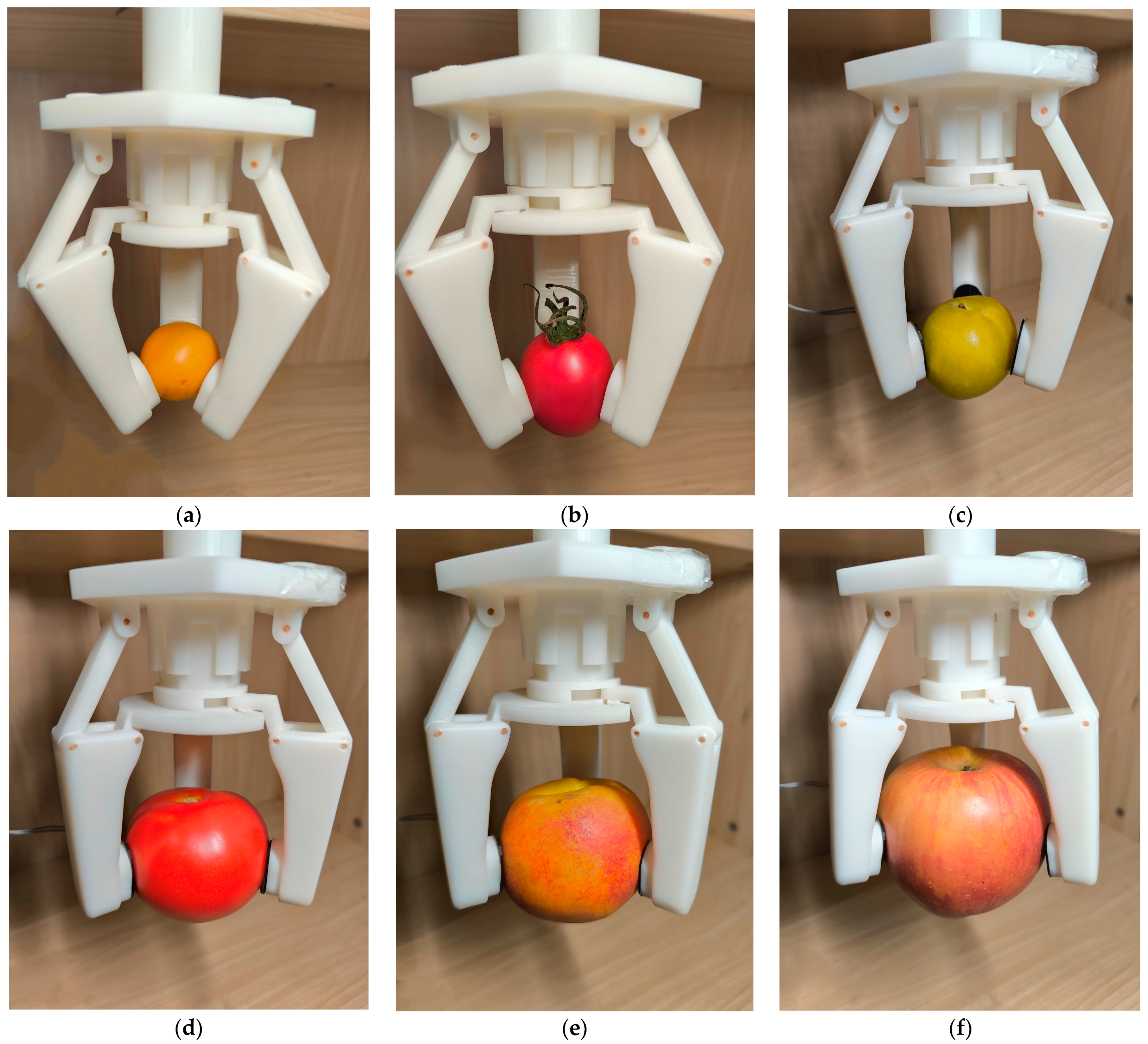
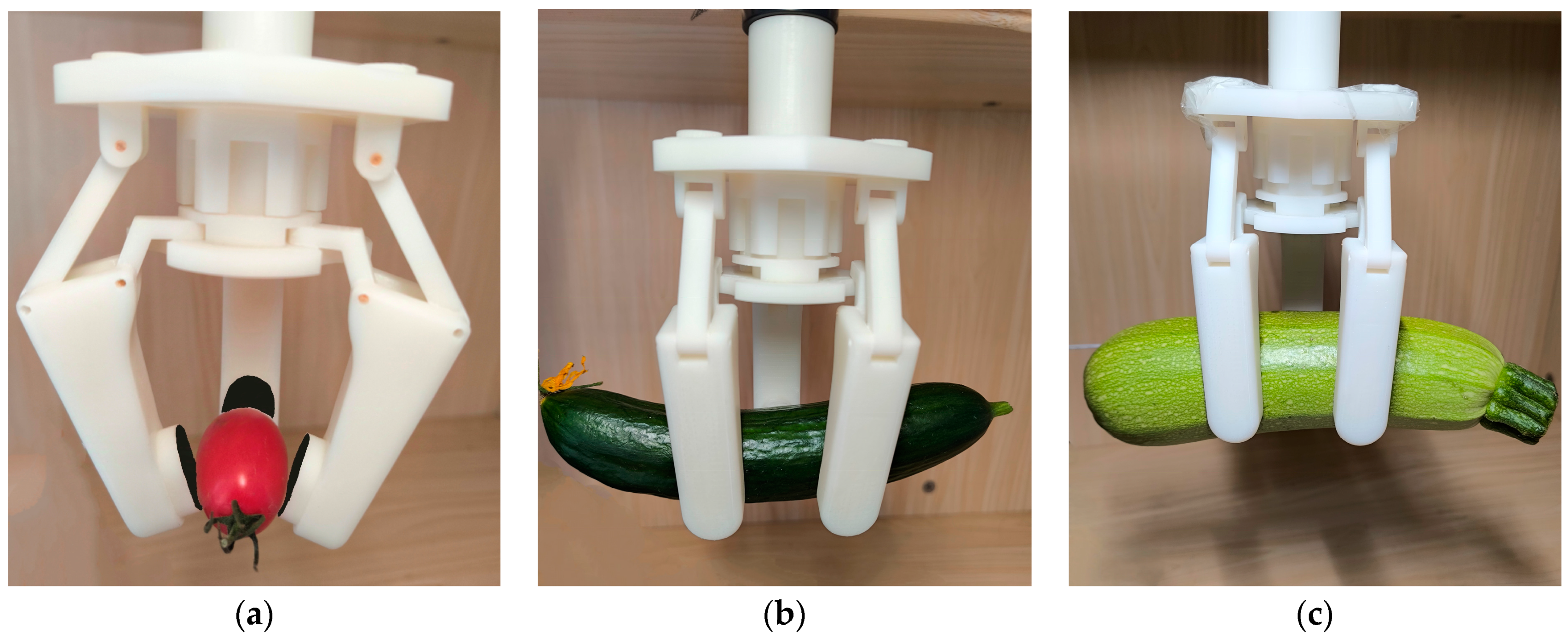
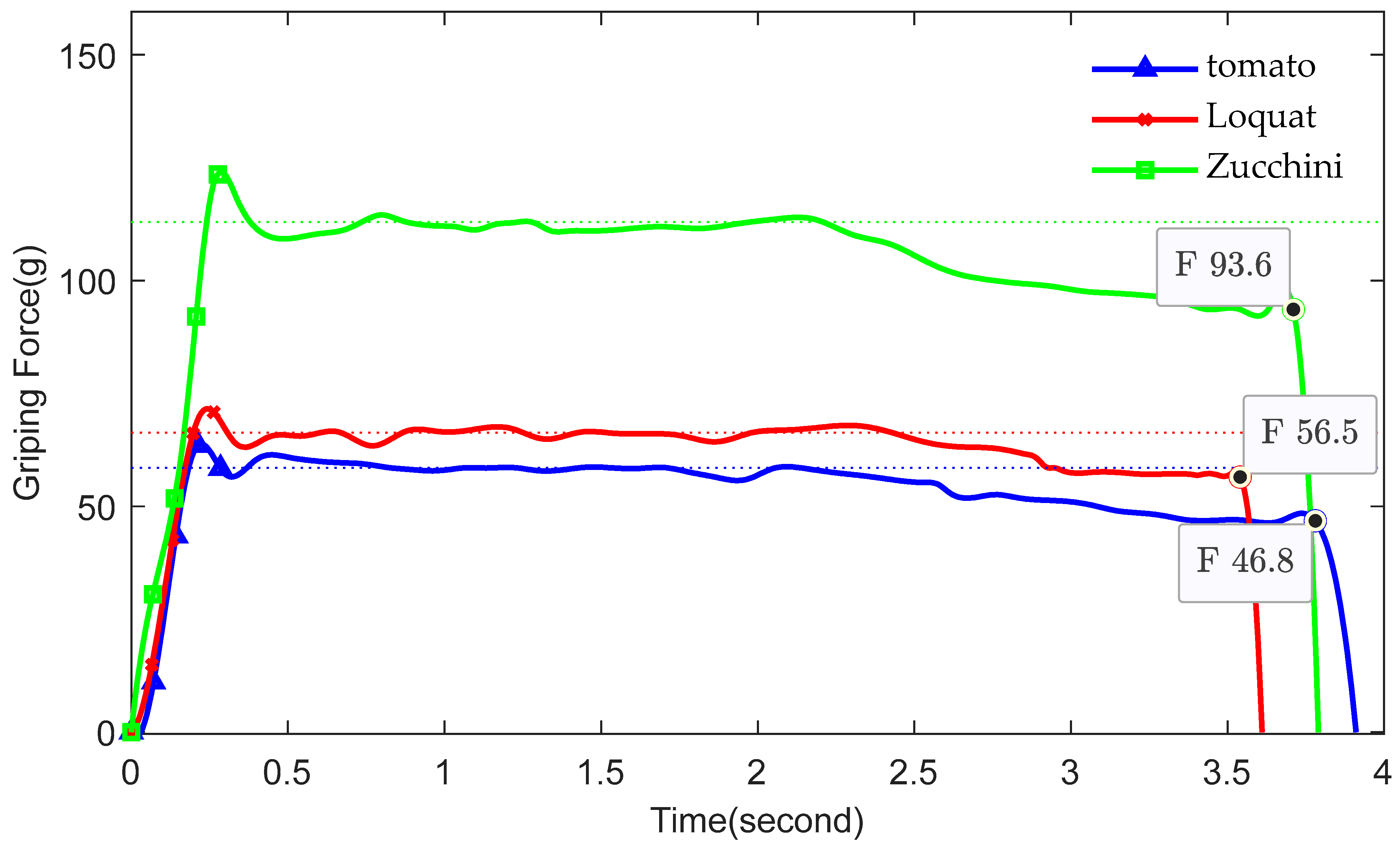
4. Experimental Results

A thin-film resistive force sensor module with the readings shown in Figure 11 is used. This can accurately and easily measure the contact force between the gripper and the fruit with an error of less than 5%. The effective sensing area of the thin-film resistance sensor has a diameter of 16 mm and a measurement range of 5~2000 g.
The design model is printed one by one, and the assembled robotic gripper is used to grab fruits. We paste the resistance sensor between the rubber layer and the finger, adjust the position to make the measurement more accurate, and then set the initial state to zero, as shown in Figure 11, and then we carry out the grab measurement experiment. In the actual grasping process, the mechanical claw grasps the fruit in a moving state, and the test of stable grasping force includes factors such as slight swinging motion. The grasping stability and finger-grasping behaviors of fruits of different shapes are investigated.
We weigh and measure the size parameters of the individual fingers that the grabbed target fruit, before adjusting the robotic gripper to grasp and measure the force. The better circular feature selects three fingers to grasp each other at about 120° and fine-adjusts the rotation angle to make the fingers more closely fit the surface of the grasping object. The kinds of fruit that were successfully captured are shown in Figure 12. Then, the robotic gripper was moved and shaken; the grasp was stable, and there was no obvious damage to the surface of the fruit. It can be seen that for small spherical fruits, it has an advantage for grasping, and its stable grasping mainly depends on the geometric position of the gripper. The size parameters and grip force results for each fruit are shown in Table 3.
We weigh and measure the size of the grasped object. We adjust the fixture to maximize the contact area between each finger and the fruit, and then we grab and measure the gripping force. At the same time, we consider the influence of the grasping position of the elongated fruit on the stable grasping force and grasping balance. The size and force test results for each grab target are shown in Table 4.
A completely cylindrical cherry fruit is selected for the grasping test. For three-finger grasping angles that are close to symmetry, the whole robotic gripper needs to be rotated so that the grasping attitude can be successfully and stably grasped. It is difficult to identify and adjust grasping, and it is not conducive to improving grasping efficiency. By rotating two rotating fingers, the contact area with the fruit surface is adjusted. The grasping effect is shown in Figure 13a. The compatibility of the robotic gripper is then further explored for grasping larger, longer, columnar-shaped fruits. The grasp effect is shown in Figure 13b,c. For the irregular bending of long-strip fruits and vegetables, we only adjust the finger angle, which can greatly reduce the force required for stable grasping. Grasping is stable and reliable in a moving and shaking state.
Tomatoes, cucumbers, and summer squash with high surface and biological quality requirements are selected for an in-depth study of grasping force. The grasping forces during the grasping processes was recorded and plotted, as shown in Figure 14. The average value of stable grasping is obtained near the dotted line position in Figure 14. From the initial lifting of the fruit, the grasping force increases first and then tends to be stable, and the mechanical claw is slowly released in the latter half to determine the value of its sliding grip force. We then measure the grasping force at the most reasonable maximum sliding, as indicated in Figure 14. The dashed lines at different positions in the figure represent the average gripping force during the measurement process. After grasping, there is no obvious damage on the surface, and the measurement results are stable.

5. Conclusions

A well-designed robot gripping mechanism based on a three-finger gripper for the low-damage grasping of spherical and cylindrical fruits has been proposed. Of the three fingers, two are rotatable for stable picking and fruit shape adaptation. Through the mathematical relationship between the driving force and the grasping force, the grasping index is established to optimize the fixture structure parameters to maximize the grasping force stability and grasping ability. The simulations and experiments show that the gripper can be used for spherical and cylindrical fruit, and the weights range from 8 to 300 g, while the diameters range from 9 to 122 mm. Future research can verify the impacts of more types of fruit grasping and mechanical claw materials on grasping, as well as plan the complex trajectory of the robot gripper for fruit harvesting and then harvest directly from the fruit tree using the mobile platform.

Author Contributions

Conceptualization, Y.X. and M.L.; methodology, Y.X.; software, R.X.; validation, Y.X. and M.L.; formal analysis, Q.X.; investigation, R.X.; resources, Y.X.; data curation, M.L.; writing—original draft preparation, Y.X.; writing—review and editing, M.L.; visualization, Q.X.; supervision, R.X.; project administration, Y.X.; funding acquisition, M.L. All authors have read and agreed to the published version of the manuscript.

Funding

This research was funded by the Jiangsu Province Key Research and Development Project, grant number BE2022062, and the Open Foundation of Fujian’s Key Laboratory of Green Intelligent Drive and Transmission for Mobile Machinery, grant number GIDT-202307.

Data Availability Statement

The data presented in this study are available on request from the corresponding author due to a third-party confidentiality agreement.

Conflicts of Interest

The authors declare no conflicts of interest.

References

  1. Kovarikova, Z.; Duchon, F.; Trebula, M.; Nagy, F.; Dekan, M.; Labat, D.; Babinec, A. Prototyping an intelligent robotic welding workplace by a cyber-physic tool. Int. J. Adv. Manuf. Tech. 2023, 125, 4855–4882. [Google Scholar] [CrossRef]
  2. Wang, Z.J.; Zhu, B.C.; Yang, Y.; Li, Z.X. Research on Identifying Robot Collision Points in Human–Robot Collaboration Based on Force Method Principle Solving. Actuators 2023, 12, 320. [Google Scholar] [CrossRef]
  3. Li, Z.; Li, S.; Luo, X. A Novel Machine Learning System for Industrial Robot Arm Calibration. IEEE Trans. Circuits Syst. II Express Briefs 2024, 71, 2364–2368. [Google Scholar] [CrossRef]
  4. Bonci, A.; Gaudeni, F.; Giannini, M.C.; Longhi, S. Robot Operating System 2 (ROS2)-Based Frameworks for Increasing Robot Autonomy: A Survey. Appl. Sci. 2023, 13, 12796. [Google Scholar] [CrossRef]
  5. Zhang, D.; Hu, J.B.; Cheng, J.; Wu, Z.G.; Yan, H.C. A Novel Disturbance Observer Based Fixed-Time Sliding Mode Control for Robotic Manipulators with Global Fast Convergence. IEEE/CAA J. Autom. Sin. 2024, 11, 661–672. [Google Scholar] [CrossRef]
  6. Zhang, J.; Kang, N.B.; Qu, Q.J.; Zhou, L.H.; Zhang, H.B. Automatic fruit picking technology: A comprehensive review of research advances. Artif. Intell. Rev. 2024, 57, 54. [Google Scholar] [CrossRef]
  7. Wang, Z.H.; Xun, Y.; Wang, Y.K.; Yang, Q.H. Review of smart robots for fruit and vegetable picking in agriculture. Int. J. Agric. Biol. Eng. 2022, 15, 33–54. [Google Scholar]
  8. Zhang, B.H.; Xie, Y.X.; Zhou, J.; Wang, K.; Zhang, Z. State-of-the-art robotic grippers, grasping and control strategies, as well as their applications in agricultural robots: A review. Comput. Electron. Agric. 2020, 177, 105694. [Google Scholar] [CrossRef]
  9. Trung, T.V.; Iwasaki, M. Fast and precise positioning with coupling torque compensation for a flexible lightweight two-link manipulator with elastic joints. IEEE/ASME Trans. Mechatronics 2023, 28, 1025–1036. [Google Scholar]
  10. Cheng, C.; Fu, J.; Su, H.; Ren, L.Q. Recent Advancements in Agriculture Robots: Benefits and Challenges. Machines 2023, 11, 48. [Google Scholar] [CrossRef]
  11. Xu, X.; Wang, Y.N.; Jiang, Y.M. Review of Research Advances in Fruit and Vegetable Harvesting Robots. J. Electr. Eng. Technol. 2024, 19, 773–789. [Google Scholar]
  12. Rong, J.C.; Wang, P.B.; Wang, T.J.; Hu, L.; Yuan, Y. Fruit pose recognition and directional orderly grasping strategies for tomato harvesting robots. Comput. Electron. Agric. 2022, 202, 107430. [Google Scholar] [CrossRef]
  13. Gorjian, S.; Ebadi, H.; Trommsdorff, M.; Sharon, H.; Demant, M.; Schindele, S. The advent of modern solarpowered electric agricultural machinery: A solution for sustainable farm operations. J. Clean. Prod. 2021, 292, 126030. [Google Scholar] [CrossRef]
  14. Zahidi, U.A.; Khan, A.; Zhivkov, T.; Dichtl, J.; Li, D.; Parsa, S.; Hanheide, M.; Cielniak, G.; Sklar, E.I.; Pearson, S.; et al. Optimising robotic operation speed with edge computing via 5G network: Insights from selective harvesting robots. J. Field Robot. 2024, 1–19. [Google Scholar] [CrossRef]
  15. Feng, J.T.; Yang, Q.Y.; Tian, H.; Wang, Z.P.; Tian, S.J.; Xu, H.R. Promising real-time fruit and vegetable quality detection technologies applicable to manipulator picking process. Int. J. Agric. Biol. Eng. 2024, 17, 14–26. [Google Scholar]
  16. Nie, H.; Zhao, Z.; Chen, L.; Lu, Z.; Li, Z.; Yang, J. Smaller and Faster Robotic Grasp Detection Model via Knowledge Distillation and Unequal Feature Encoding. IEEE Robot. Autom. Let. 2024, 9, 7206–7213. [Google Scholar] [CrossRef]
  17. Sánchez-Molina, J.A.; Rodríguez, F.; Moreno, J.C.; Sánchez-Hermosilla, J.; Giménez, A. Robotics in greenhouses. Scoping review. Comput. Electron. Agric. 2024, 219, 108750. [Google Scholar] [CrossRef]
  18. Wang, F.L.; Urquizo, R.C.; Roberts, P.; Mohan, V.; Newenham, C.; Ivanov, A.; Dowling, R. Biologically inspired robotic perception-action for soft fruit harvesting in vertical growing environments. Precis. Agric. 2023, 24, 1072–1096. [Google Scholar] [CrossRef] [PubMed]
  19. Li, Z.; Yuan, X.; Wang, C. A review on structural development and recognition–localization methods for end-effector of fruit–vegetable picking robots. Int. J. Adv. Robot. Syst. 2022, 19, 17298806221104906. [Google Scholar] [CrossRef]
  20. Oliveira, F.; Tinoco, V.; Magalhães, S.; Santos, F.N.; Silva, M.F. End-Effectors for Harvesting Manipulators-State of the Art Review. In Proceedings of the 2022 IEEE International Conference on Autonomous Robot Systems and Competitions (ICARSC), Santa Maria da Feira, Portugal, 29–30 April 2022. [Google Scholar]
  21. Xiong, Y.; Ge, Y.Y.; From, P.J. An obstacle separation method for robotic picking of fruits in clusters. Comput. Electron. Agric. 2020, 175, 105397. [Google Scholar] [CrossRef]
  22. Chappell, D.; Bello, F.; Kormushev, P.; Rojas, N. The Hydra Hand: A Mode-Switching Underactuated Gripper with Precision and Power Grasping Modes. IEEE Robot. Autom. Let. 2023, 8, 7599–7606. [Google Scholar] [CrossRef]
  23. Zhou, J.L.; Zhang, Y.Y.; Wang, J.P. A Dragon Fruit Picking Detection Method Based on YOLOv7 and PSP-Ellipse. Sensors 2023, 23, 3803. [Google Scholar] [CrossRef] [PubMed]
  24. Lu, Q.J.; Baron, N.; Clark, A.B.; Rojas, N. Systematic object-invariant in-hand manipulation via reconfigurable underactuation: Introducing the RUTH gripper. Int. J. Robot. Res. 2021, 40, 1329–1562. [Google Scholar] [CrossRef]
  25. Gu, L.H.; Huang, Q.J. Adaptive Impedance Control for Force Tracking in Manipulators Based on Fractional-Order PID. Appl. Sci. 2023, 13, 10267. [Google Scholar] [CrossRef]
  26. Torielli, D.; Bertoni, L.; Fusaro, F.; Tsagarakis, N.; Muratore, L. ROS End-Effector: A Hardware-Agnostic Software and Control Framework for Robotic End-Effectors. J. Intell. Robot. Syst. 2023, 108, 70. [Google Scholar] [CrossRef]
  27. Ceccarelli, M. Fundamentals of Mechanics of Robotic Manipulation, 2nd ed.; Springer: Cham, Switzerland, 2022; pp. 323–341. [Google Scholar]
Figure 1. The gripper structure based on three fingers and a rotatable mechanism.
Actuators 13 00338 g001
Figure 2. The rotation position of fingers: (a) rotation method (b) initial position, (c) positive limit position, and (d) negative limit position.
Actuators 13 00338 g002
Figure 3. The working process diagram of the robotic gripper.
Actuators 13 00338 g003
Figure 4. Gripper composition and structure analysis: (a) gripper model; (b) gripper mechanism diagram; (c) finger stress analysis.
Actuators 13 00338 g004
Figure 5. Static simulation parameter setting: (a) fixture; (b) normal uniform load.
Actuators 13 00338 g005
Figure 6. Simulation results of static stress analysis: (a) stress; (b) displacement.
Actuators 13 00338 g006
Figure 7. Motion simulation parameter.
Actuators 13 00338 g007
Figure 8. The angular velocity of the gripper finger at different driving speeds.
Actuators 13 00338 g008
Figure 9. Angular acceleration of gripper finger at different driving speeds.
Actuators 13 00338 g009
Figure 10. Velocity of fingers at different driving speeds.
Actuators 13 00338 g010
Figure 11. Grasping measurement state of robotic gripper before experiment.
Actuators 13 00338 g011
Figure 12. Grasping states of different spherical fruits: (a) loquat, (b) cherry, (c) citrus, (d) tomatoes, (e) yellow peach, and (f) apple.
Actuators 13 00338 g012
Figure 13. Grasping states of different long column strip objects: (a) cherry, (b) loquat, and (c) zucchini.
Actuators 13 00338 g013
Figure 14. The curve of the grasping forces of tomato, loquat, and zucchini.
Actuators 13 00338 g014
Table 1. Limits ranges of designed parameters of the gripper.
ViableMin (mm)Max (mm)
l13060
l21520
r3030
Table 2. ABS and rubber material properties and applications.
IndexABSRubber
Yield strength (MPa)509.23737
Tensile strength (MPa)3013.7817
Modulus of elasticity (N/m2)2 × 1096.1 × 106
Poisson’s ratio0.3940.49
Mass density (kg/m3)10201500
Shear modulus (N/m2)3.189 × 1082.9 × 106
Table 3. Spherical fruit capture data.
ObjectWeight (g)Max Diameter (mm)Min Diameter (mm)Grip Force (g)Max Slip Force (g)
Loquat816.815.4--
Cherry1523.522.4--
Citrus4649.444.523.4-
Tomato11668.564.658.546.8
Yellow peach14867.753.466.356.6
Apple22085.579.589.374.1
Table 4. Long column strip fruit and vegetable capture data.
ObjectWeight (g)Max Diameter (mm)Length (mm)Grip Force (g)Max Slip Force (g)
Cherry21323.251.55.07-
Loquat10834.5151.266.356.6
Zucchini29056.4194.1113.193.6
Disclaimer/Publisher’s Note: The statements, opinions and data contained in all publications are solely those of the individual author(s) and contributor(s) and not of MDPI and/or the editor(s). MDPI and/or the editor(s) disclaim responsibility for any injury to people or property resulting from any ideas, methods, instructions or products referred to in the content.

