Article

Local Heat Transfer Analysis of Dual Sweeping Jet, Double Sweeping Jets, and Double Circular Jets Impinging at a Flat Surface

1
School of Mechanical Engineering, Shanghai Jiao Tong University, Shanghai 200240, China
2
School of Marine Science and Technology, Northwestern Polytechnical University, Xi’an 710072, China
*
Author to whom correspondence should be addressed.
Actuators 2025, 14(3), 109; https://doi.org/10.3390/act14030109
Submission received: 27 January 2025 / Revised: 14 February 2025 / Accepted: 16 February 2025 / Published: 21 February 2025

Abstract

:
A sweeping jet is commonly preferred over a steady jet owing to its ability to better cool the region away from the strong core of an impinging jet. For industrial applications, it is important to study the thermal fields of oscillating jets in a multi-jet configuration to focus on the region that falls between the two consecutive fluidic oscillators and, hence, suggest a mechanism to uniformly cool the targeted flat surface. A comparative experimental study of dual sweeping jets (DSJs), double sweeping jets (DbSJs), and double circular jets (DbCJs) was conducted at different jet-to-plate spacings, various Re numbers, and three aspect ratios. The multi-circular and sweeping jets were impinged on a flat hot surface, which was heated at a constant flux of current, and thermocouples were employed to efficiently collect the time-averaged heat transfer distribution along the sweeping and transverse directions. It was determined that heat transfer, in terms of the Nusselt number, generally increased with increasing Re number and reduced the jet-to-wall spacing for the DSJ, DbSJ, and DbCJ, with some minor exceptions. The relative performance of these fluidic devices suggested that the best performance of DSJ was at small spacing and higher Re, DbSJ at moderate spacing and lower Re, and DbCJ at moderate spacing and moderate Re. The mutual comparison showed that along the sweeping motion, in the central region, DbCJ was better than both DSJ and DbSJ; in the right region, DSJ performance was far better than DbCJ and DbSJ; in the left region, DSJ was better than DbSJ when comparing the respective centers of DSJ and DbSJ. The dominance of DSJ over DbSJ at the centers of their respective bodies even extends in the transverse direction. Finally, for higher aspect ratios, the DSJ performed better in the outer regions, while the DbSJ performed well in the central region. Similarly, for both DSJ and DbSJ unanimously, the effect of changing the aspect ratio is interesting as initially, the Nu values increase for a higher aspect ratio, but by increasing the AR further, it causes a divergence of the fluidic volume from the central region to the surrounding region.

1. Introduction

An impinging jet is a simple device with a large potential to transfer mass and energy between a working fluid and a target surface through forced convection [1]. It has many heat and mass transfer-related industrial applications like flow separation control [2], vortex generator [3], cleaning of soft-solid soil layers from vertical and horizontal surfaces [4], water treatment of hot steel plates [5] and cooling turbine-vane internally [6] by jet impingement. Attalla et al. [7] studied circular and squared holes and their relative heat transfer performance, and Lutum et al. [8] evaluated cylindrical holes for film-cooling applications. Kohli et al. [9], Zhou et al. [10], Forouzanmehr et al. [11], Goldstein et al. [12], and Carlomagno et al. [13] determined the effects of parameters like freestream turbulence, changing the curvature of an impinged surface, multi-jet impingement to achieve a uniform heat flux distribution, impinging jet behavior with and without crossflow, and jet-to-plate spacing.
In addition to the steady jet, the sweeping jet mechanism is simple and has been extensively used for flow control [14], combustion [15], lift enhancement [16], drag reduction [17], noise control [18], and recently, for blood plasma separation [19] and oil-emulsion separation [20]. It is produced by injecting a pressurized fluid into a device called a fluidic oscillator, and resultantly, a self-induced and self-sustaining oscillating jet is produced. The sweeping jet is robust, agile, controllable, and has a large area of impact. Woszidlo et al. [21] categorized it into feedback-free, one feedback channel, and two-feedback channels fluidic oscillators. Some authors have also developed novel designs like microfluidic oscillators [22], two-layered master and slave designs [23], and dual sweeping impinging jets [24] to extend its scope of application. Moreover, its internal and external flow fields have been studied extensively by many authors, including Pandey et al. [25] (internal flow field) and Ostermann et al. [26] (external flow fields).
A sweeping jet produced by a two-feedback channel fluidic oscillator has been commonly employed for heat transfer enhancement applications using different measuring techniques. The methodologies like Phosphor Thermometry, Temperature Sensitive Paint technique, Infrared Thermography (for film cooling), and Numerical methodology are popular and have been conveniently used by many researchers, including Kim et al. [27], Zhou et al. [28], Hossain et al. [29], and Joulaei et al. [30]. Park et al. [31] used a fundamental and reliable technique of using thermocouples to determine the thermal field of a flat surface impinged by a sweeping jet; and reported the effects of varying Re numbers and jet-to-wall spacing. Similarly, Kim et al. [32] investigated the potential of a sweeping jet impinging on a curved surface under various Re numbers and jet-to-wall spacings using thermocouples. Recently, Gomes et al. [33] used simple flux sensors with a flat hotbed to analyze the heat transfer potential of an impinging sweeping jet.
In the literature, there are many applications of sweeping jets produced by a fluidic oscillator with various parameters and boundary conditions for heat transfer augmentation. All these cases, according to the authors’ best knowledge, deal with sweeping jets in isolation, and hardly a scenario was found where fluidic oscillator impact was studied in a multi-jet configuration. It is important to study multi-sweeping-jet formation since it has the potential for efficient heat treatment of the area that falls in between the two consecutive fluidic oscillators. One such device was developed by Tomac and Gregory [34,35], who merged two fluidic oscillators by sharing a feedback channel. Wen et al. [24] studied the flow dynamics of this novel device experimentally and reported that two sweeping jets are produced by this device, which together form a dual sweeping jet (DSJ)—since both jets are synchronous, especially at low Re numbers. However, a numerical study was conducted by Zubair et al. [36] to further the comprehension of the flow fields of the DSJ at various Re numbers and aspect ratios. Additionally, in another numerical study published by Eghtesad et al. [37], they called it a Twin Turbulent Sweeping Imping Jet (TTSIJ) to study its flow and thermal fields using the k-w SST turbulence model and various governing parameters. It was felt that there was a need to experimentally explore the thermal dynamics of this device using the simplest and most reliable setting of thermocouples attached to a flat hotbed and compare it to the thermal fields of two fluidic oscillators and two circular jets in a multi-jet configuration. It is also necessary to make this comparison as a dual sweeping jet (DSJ) seems to have the potential to perform better than two consecutive sweeping and circular jets—hereafter called double sweeping jets (DbSJ) and double circular jets (DbCJ), respectively—especially in a region that falls in between the two consecutive devices.
This article experimentally investigates the heat removal potentials of dual sweeping jets, double sweeping jets, and double circular jets generated by DSJ, DbSJ, and DbCJ fluidic devices, respectively, using numerous T-type thermocouples placed on top of a flat surface. The target surface was heated with a constant flux of current, and cool air was impinged upon it through these devices at jet-to-wall spacings of 3 hd, 5 hd, 7 hd, and 9 hd. The effects of varying the Reynolds number (8 k, 12 k, 16 k, and 20 k) and throat aspect ratios (1, 1.2, and 1.56) on the heat transfer capabilities were studied thoroughly (for both sweeping and transverse directions of flow). In this study, a hydraulic diameter of 5 mm was used at each throat and for all devices. Consequently, the 2D thermal fields of the dual sweeping jets (DSJs), double sweeping jets (DbSJs), and double circular jets (DbCJs) were compared to suggest an efficient fluidic device for uniform cooling, as a region between two consecutive single-jet fluidic devices remains heated and causes non-uniform cooling efficiency or thermal gradient.

2. Experimental Procedure

2.1. Fluidic Devices

A fluidic oscillator is a device with no moving parts, one or more converging inlets, and a diverging outlet. The inlet power nozzle/s opens into a mixing chamber, while an outlet may expand into two discrete outlets or an open field for the jet to sweep from left to right and vice versa. The mixing chamber is the region that governs the internal fluid dynamics of the fluidic oscillator and causes fluid oscillation. A fluidic oscillator may have one or two-feedback channels immediately before the throat nozzle. At this juncture, the freestream enters the feedback channel and propagates a pressure wave ahead of it. This causes the mainstream to fluctuate for a fluidic oscillator with one feedback channel in one direction, which in turn generates another pressure wave in the opposite direction. In a fluidic oscillator with two-feedback channels, the fluid’s inherent turbulence causes it to attach to either the left or right island of the mixing chamber. The stream of the fluid remains attached to this wall due to the Coanda Effect and meanwhile feeds back some liquid through the feedback channel to the fluid entering the mixing chamber. This phenomenon generates a recirculation bubble under the jet attached to the wall. The bubble grows in strength and pushes the jet away from it. This push-away behavior depletes fluid flow from one feedback channel and strengthens the other, and the whole process repeats itself, causing internal and external oscillation—the whole phenomenon has been reported in further detail by Sieber et al. [38] with internal and external fluctuating behaviors separately.
Traditionally, single circular and sweeping jets are compared to determine their cooling effects under given conditions. Here, the objective is to understand the heat treatment of a region that falls between the two consecutive jets; therefore, it is necessary to have fluidic devices attached next to each other. To simplify the experimental setup, two fluidic devices were designed, one to house two consecutive circular jets and the other to house two consecutive sweeping jets, as shown in Figure 1a and Figure 1b, respectively. The device shown in Figure 1b was formed using a simple design of a fluidic oscillator, as patented by Stouffer [39], and has been thoroughly researched by many authors, including Wen et al. [40], Wen et al. [41], and Park et al. [31]. Wen et al. [40] visualized its flow fields using particle image velocimetry to understand its unsteady behavior. Wen et al. [41] explored its geometric variations and determined the resultant effects on its flow dynamics. Moreover, the single-fluidic oscillator was employed by Park et al. [31] to understand its heat transfer potential. In this study, instead of using two such single-fluidic oscillators individually, they are designed to be accommodated in one housing. This method made it possible to reduce the mutual spacing between the two fluidic oscillators as much as possible. The third device, shown in Figure 1c, is a special version of a two-feedback-channel fluidic oscillator. It was developed by Tomac and Gregory [34,35] and applied by Wen et al. [24] to study the interaction of dual sweeping impinging jets at different Reynolds numbers; it was reported that this device shares a feedback channel and hence helped to produce two sweeping jets (or a dual sweeping jet) synchronized especially at low Re numbers. This study intends to explore the heat transfer enhancement potential of a dual sweeping jet (DSJ) fluidic oscillator and compare its performance against double sweeping jets (DbSJs) fluidic oscillator and double circular jets (DbCJ) fluidic oscillator—as has been shown in Figure 1c, Figure 1b and Figure 1a, respectively—at different Re numbers, jet-to-wall spacing, and aspect ratios.
The hydraulic diameter or characteristic length of all these fluidic oscillators at the throat was 5 mm. These devices were professionally printed by a LIANTAI (Shanghai, China) 3D printer using white photosensitive resin at an accuracy of 0.2 mm (which is much smaller than the characteristic length and hence produces minimal surface roughness effects). The overall length, width, and depth of all devices were kept similar, and all inlets were circular, with their distance to the exit of the device kept equal. As shown in Figure 1a, the gap between two consecutive circular throats inside the DbCJ device is 23.80 mm, which is similar to the gap identified between two consecutive throats of the DSJ (Figure 1c). However, in Figure 1b, the two throats of the DbSJ are separated by a distance of 35.60 mm. This difference of 11.80 mm is necessary to have as part of it (5.80 mm approx.) comes from the addition of another feedback channel in the DbSJ; each feedback channel is 5.82 mm in width, and the remaining 6 mm comes from two consecutive walls (3 mm each). A wall thickness of 3 mm was selected considering that two fluidic oscillators would be printed separately and placed neck-to-neck (at zero distance between consecutive walls). For both the DbSJ and DSJ, the throat-to-exit length is 7.5 mm, the throat divergent angle is 90 degrees, the width at the nozzle exit is 20 mm, and the width of each feedback channel is 5.82 mm. The DSJ and DbSJ have square throats for AR1.0 (5 mm × 5 mm) and rectangular throats for AR1.20 (5.5 mm × 4.6 mm) and AR1.56 (6.4 mm × 4.1 mm), where the longest dimension is along the sweeping direction (x-axis).

2.2. Air-Impingement Setup

Figure 2 shows the impingement setup for the DSJ fluidic oscillator mounted on a stand (3D printed with PLA material) using holding screws. The mountable stand was held in the air with the help of two vertical stairs (one on each side) for which each step is 5 mm high so that the height of a fluidic oscillator can be adjusted in increments of 1 hd. Figure 2a shows the location of the axes, where the origin of the axes is held right under the right sweeping jet (RSJ) or right circular jet (RCJ). The jet-to-wall spacing (H) is measured in hydraulic diameter (hd). i.e., 3 hd, 5 hd, 7 hd, and 9 hd, and referenced from the throats of fluidic devices. Since DSJ and DbSJ have a throat-to-exit distance of 7.5 mm while DbCJ throat is right at its exit, therefore, H was adjusted unanimously for DbCJ to match the exact values. Further, Figure 2a shows a plexiglass sheet of 20 mm thickness positioned on an experimental bed to work as insulation and avoid conductive losses from the bottom of a heated surface. An L-shaped polyimide thin conductive sheet of power 5 W 12 V was pasted on top of the insulated plexiglass sheet, and its terminals were connected to a DC power supply (shown in Figure 3). Next, the conductive sheet (TECHINNO (Suzhou, China) US300, 3 W/mK conductivity) of thickness 2 mm was attached to the top of this heating surface with the help of the conductive sheet’s double-sided tape. It was important to use this sheet as without it the steel plate would conduct the current directly instead of getting heated by the flowing current. So, an L-shaped steel plate of thickness 2 mm was positioned on top of the conductive sheet using its double-sided tape.
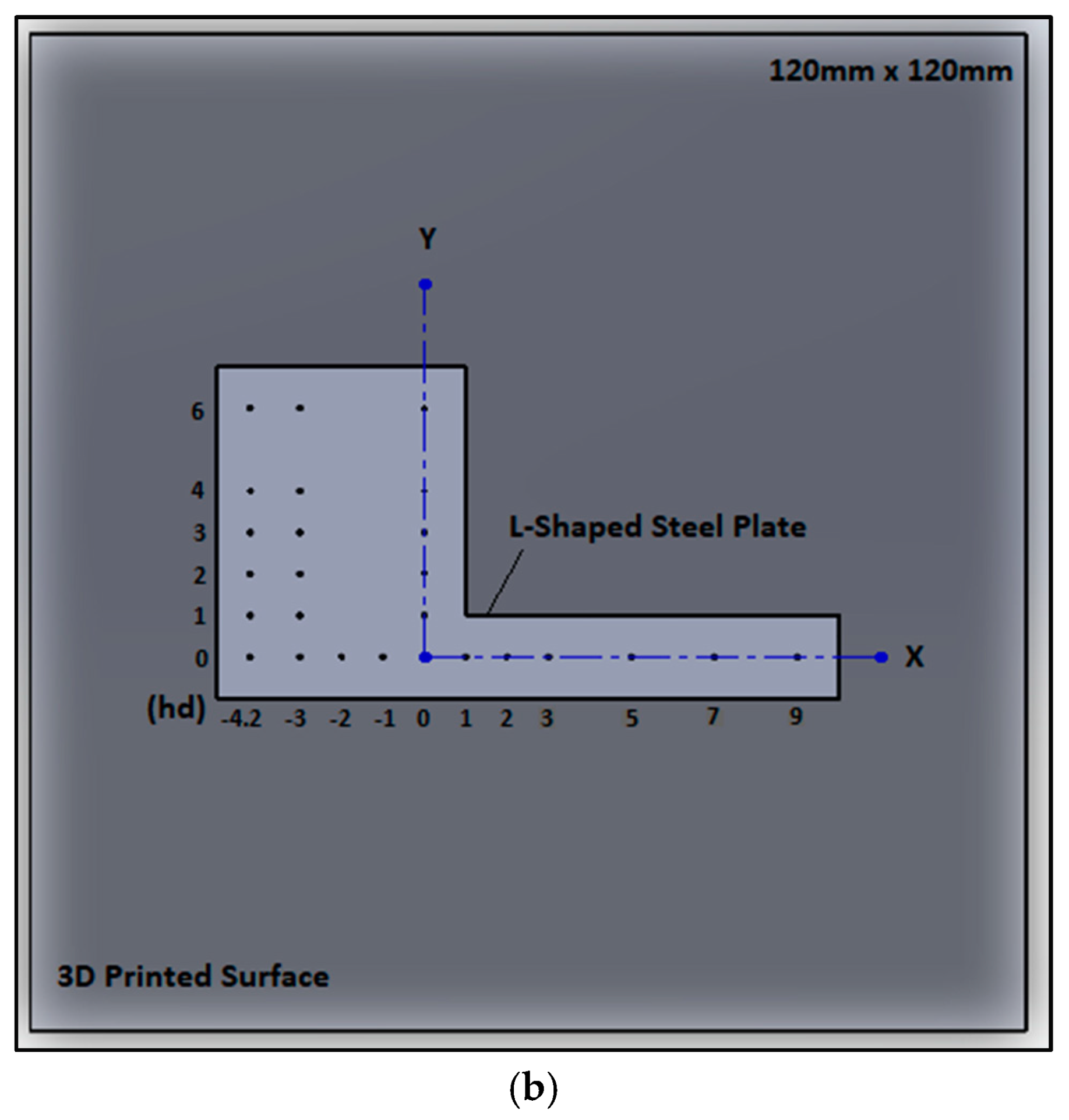
The plate of steel is helpful in conducting heat because of its high thermal conductivity, and secondly, it is possible to weld the thermocouples on top of its surface using HOTSPOT II (DCC Corporation, Pennsauken, NJ, USA) Thermocouple Welder. A specific L-shaped steel plate was used intentionally since the heated volume, heat generation power of the polyimide sheet, and flow rate impinged upon the surface from fluidic oscillators were all interlinked parameters. A sheet with a larger heated volume demands a higher flow rate and exhibits poor performance at increased jet-to-wall spacings. Therefore, an extra volume was shredded from the sheet, and only the surface was selected to accommodate sufficient thermocouples for analysis along both axes. The location of the thermocouples can be seen in Figure 2b; 11 T-type thermocouples (OMEGA, 1 mm tip diameter) were welded along the x-axis and five thermocouples along each y-axis (0 hd, −3 hd, and −4.2 hd). Authors like Park et al. [31] and Kim et al. [32] have also utilized thermocouples to gauge the heat enhancement performance of impinging sweeping jets on flat and curved surfaces, respectively. The polyimide heating sheet, conductive sheet, and steel plate assembly were housed in a 3D printed surface (120 mm × 120 mm) with a thickness of 4 mm—as shown in Figure 2b.

2.3. Overall Experimental Setup

The fluidic oscillator and air-impingement setup were housed inside the Heating and Cooling Chamber—as shown in Figure 3. The external walls and removable front window of this chamber were made of an acrylic transparent sheet of 10 mm thickness, cut and holed by the EAGLE (Warsaw, Poland) Laser Cutting Machine, and glued together with the DELI 502 (Ningbo, China) Instant Adhesive. Inside the chamber, the two vertical stairs to hold the mountable stand and the mountable stand itself were 3D printed using PLA material. The chamber was designed to impinge cool air inside the chamber before conducting the experiment. Second, this chamber mitigates the convection losses that occur through the mixing of the impinging cool-air and hot air interacting with the surroundings. Additionally, this chamber helps control radiation losses from the heated surface. The polyimide heated-surface terminals connected to a constant DC power supply (HYELEC, Hong Kong, 31 V and 5 A, voltage resolution 0.01 V, current resolution 0.001 A) can also be seen in Figure 3. Next to the DC power supply is the FLUKE 2638A HYDRA Series II (Everett, WA, USA) Data Recorder, used to collect data through the connected thermocouples. The data recorder records temperature input at a frequency of one second. A Humidifier (DI1338E, Hangzhou Ltd., Hangzhou, China, 2000 W) was also used to control the moisture content of the room air, as high moisture affects the air temperature and hence the cooling efficiency of the impinging air.
Air was supplied by an air compressor (JAGUAR, Taipei, Taiwan, 1.2 MPa total capacity, 0.25 MPa minimum accuracy) through the PVC transparent connecting pipes (10 mm inner diameter) to the circular copper-soft-piping (10 mm inner diameter, 1 mm wall thickness) of the thermal bath. The coiling of soft-copper-piping of the thermal bath was long enough (8 m) so it may heat the passing air sufficiently to maintain the required conditions. A thermal bath (SHAOXING Ltd., Shaoxing, China, HH600, 100C max, 0.1C accuracy) was used to maintain the air temperature at constant and required temperatures. The air that passed through this thermal bath is called “cool air” since it is maintained at a relatively very low temperature in comparison to the temperature of the targeted surface. This air then passed through the SMC 1 MPa Pressure Regulator to control the supplied pressure of the incoming air. To measure the flow rate of the compressed air, an SMC Flowmeter (Tokyo, Japan, PFM7201S, 1LPM accuracy) of 200LPM measuring capacity was used. Finally, the air passed through an ASMIK Digital Pressure Gauge (Singapore, 0.01 kPa accuracy) and PVC transparent connecting pipes (10 mm inner diameter) before entering the Heating and Cooling Chamber.

2.4. Setup Validation and Experimental Run

Firstly, at room temperature (24–26 °C), the air moisture was controlled using a humidifier and kept below 40%. During a series of experiments, it was noted that at high moisture content and high flow rates, like 16 k or 20 k, the compressed air started condensing moisture and formed water droplets in the upcoming air. Therefore, moisture was controlled, especially at high Re numbers, to maintain a high and consistent air quality for the whole set of measurements. Secondly, it was observed that the impinging air temperature fluctuated with variations in Re i.e., 8 k, 12 k, 16 k, and 20 k, and increased at higher Re numbers. Therefore, the thermal bath temperature was adjusted to maintain a constant impinging temperature (30 °C) at the target wall for each set of data acquisition. Thirdly, all the thermocouples were calibrated with a standard mercury thermometer (HENGSHUI (Hengshui, China) Instrument Ltd., 0–50 C range, 0.01 c error, 0.1 c accuracy) and found a maximum temperature error of value 0.56%.
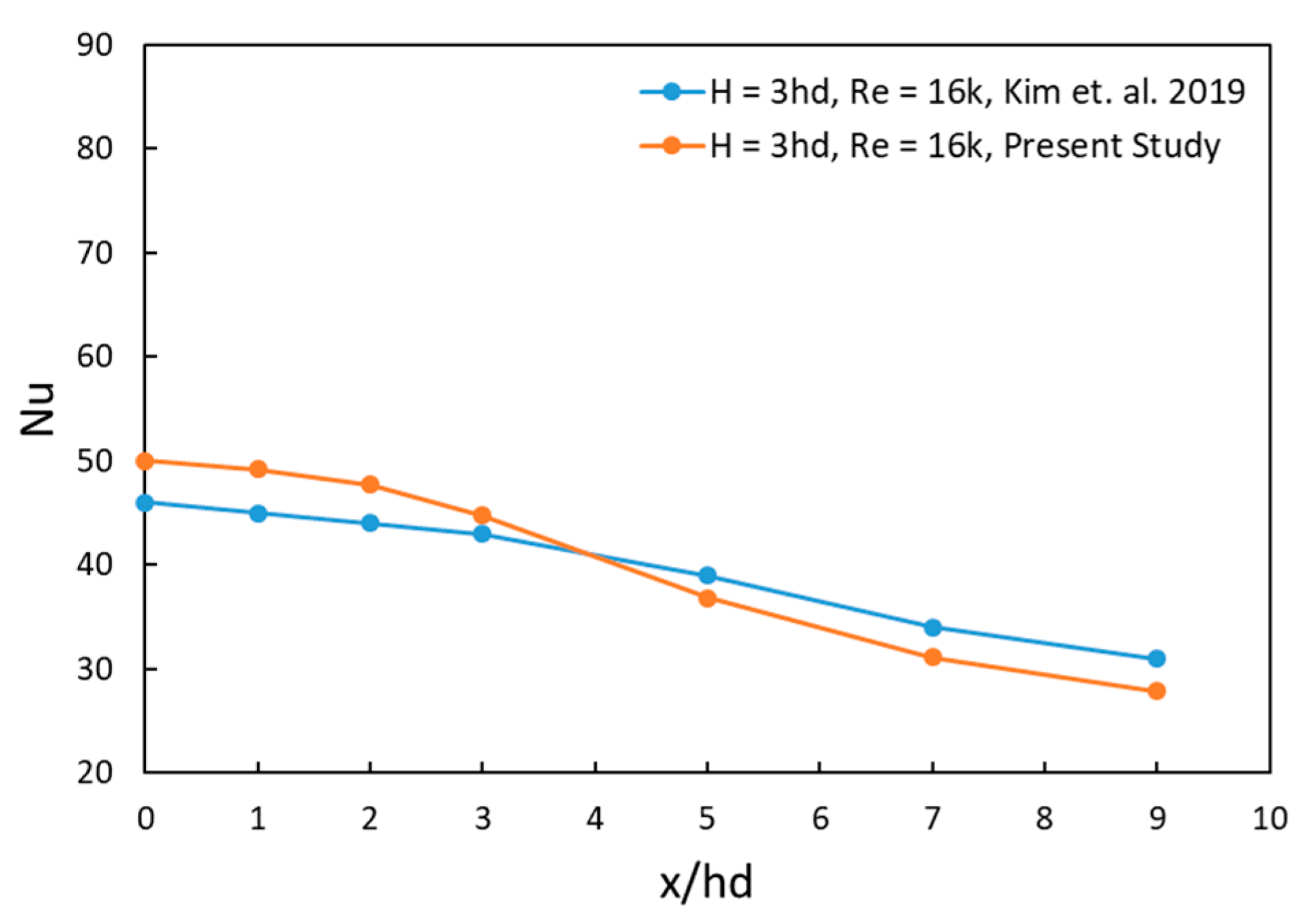
Kim et al. [27] investigated the heat performance of steady square and sweeping jets impinging vertically at a flat wall and collected data using the Phosphor Thermometry technique. The steady jet they used had a throat with a hydraulic diameter of 5 mm, and they reported the Nusselt number distribution, as shown in Figure 4. Finally, for validation, the setup was run with a circular jet of 5 mm diameter, held at 15 mm (or 3 hd) away from the target wall, supplied with Re 16 k, and the adiabatic temperature distribution on the wall was obtained. Next, the target wall was heated with constant flux through a DC power supply of 15.36 V and 0.8 A to a polyimide heating sheet—the power was supplied for long enough that the rate of rise of temperature (collected through a thermocouple) at the surface fell below 1 °C/min. Meanwhile, the air compressor continued to run (while the flow pipes were disconnected) to stabilize the flow rate at the required condition (Re = 16 k for a validation case) and allow the air temperature to reach a constant condition (30 °C at the target wall). After stabilizing these parameters, the flow pipes were reconnected, and the flow started impinging on the heated wall. The data were collected for a long enough time that the convective heat transfer from the heated wall to the cool air stabilized, and the rate fell below 0.1 °C/min. The data were analyzed using Equation (1) to calculate the heat flux rate, q (W/m2), where A is the area of the L-shaped steel plate (30 mm × 30 mm square part, 75 mm × 10 mm strip part). The heat transfer coefficient, h (W/m2K), was determined using the adiabatic wall temperature (Tadb) and the wall temperature (Tw) after the cool air treatment of the heated wall, using Equation (2). Finally, the Nusselt number was calculated using Equation (3) with the known parameters of hydraulic diameter, hd (m), and air thermal conductivity, k (W/mK). The results of this validation run are shown in Figure 4 along with the results reported by Kim et al. [27].
q = ( V I ) A
h = q T w T a d b
N u = h . h d k
The difference between the Nusselt numbers in this study and the one conducted by Kim et al. [27] is within 10% at its maximum deviation due to the fact that we are using a circular jet with the same hydraulic diameter, while the later author used a squared jet. The squared jet has a larger area at its disposal, which slows the flow upon impingement. Secondly, the difference in technique also causes minor differences as the referenced author is using Phosphor Thermometry while we are using T-type thermocouples. The higher accuracy of the thermocouples also suggests a slight overestimation of the Nusselt values.
Moreover, the experiment was conducted for Re = 8 k, 12 k, 16 k, and 20 k (at each throat of the fluidic oscillator) and jet-to-wall spacing of H = 3 hd, 5 hd, 7 hd, and 9 hd using the DSJ, DbSJ, and DbCJ. It was assumed that the flow rate set at the flowmeter would be distributed equally into the two connecting pipes, as shown in Figure 3, and hence would cause the same Re number at each throat of the fluidic oscillator. Additionally, it was also checked through numerical simulation if there is any difference between DSJ and DbSJ in terms of either throat velocity or throat frequency if a constant flow rate is provided to each one of these fluidic oscillators. It was found that if a constant flow rate was provided to both the DSJ and DbSJ, the same values for the throat velocity and throat frequency were obtained for each of their corresponding throats. Hence, further experiments were conducted safely with mass flow rates of 60, 90, 120, and 150 SLPM for the DbCJ and 76, 112, 150, and 188 SLPM for the DSJ and DbSJ. In the next section, the data collected were analyzed along the sweeping direction (x-axis) and in three transverse directions (0 hd y-axis, −3 hd y-axis, −4.2 hd y-axis). The procedure was also repeated by varying the aspect ratios of DSJ and DbSJ at AR1.20 and AR1.56 and lastly, the comparison was made between the performance of different aspect ratios.

3. Results and Discussion

3.1. Fluidic Devices’ Behavior Along the Sweeping Direction

The experiment was run for four Re numbers, i.e., 8 k, 12 k, 16 k, and 20 k, and four jet-to-wall spacing values i.e., 3 hd, 5 hd, 7 hd, and 9 hd, were adopted for each Re number. All such cases were repeated for DSJ, DbSJ, and DbCJ, and their corresponding Nusselt number profiles were obtained, as shown in Figure 5. Each Nu-profile can be distributed into three regions: left region (−4.2 hd to −2 hd), central region (−1 hd to 1 hd), and right region (2 hd to 9 hd). It is important to reiterate that the x-axis ranges from −4.2 hd to 9 hd and the y-axis from 0 hd to 6 hd as shown in Figure 2b—and three y-axes were adopted, namely at 0 hd, −3 hd, and −4.2 hd. The center of the right sweeping jet (RSJ) or right circular jet (RCJ) of all three devices was intentionally positioned at 0 hd, and the corresponding centers of the DSJ, DbCJ, and DbSJ fluidic devices were automatically aligned with −3 hd, −3 hd, and −4.2 hd, respectively. Figure 2a shows the location of the origin of the axes with respect to the fluidic device, and Figure 2b shows the origin and the three corresponding y-axes.
The data points are at an interval of 1 hd from −5 hd to 3 hd, and afterward, the gap was increased to 2 hd in the x-axis; for the y-axis, the data points difference is of 1 hd from 0 hd to 4 hd and 2 hd for later points—as shown in Figure 2b. For all the forthcoming figures, the Nu number axis’ major distribution is 10 units and minor at 5 units. A consistent coloring scheme was adopted for better representation and quick understanding of the results: red for DSJ, black for DbSJ, and blue for DbCJ.

3.1.1. Regional Effects

It can be seen from Figure 5 that for the central region, −1 hd values are better than those of 0 hd, and 1 hd is better than both 0 hd and −1 hd values for all Re, all jet-to-wall spacing (H), and for DSJ, DbSJ, and DbCJ. For the right region, at 2 hd the Nu number values drop sharply first and then smoothly afterward up to 9 hd for all Re, all H, and for DSJ, DbSJ, and DbCJ. The left region is unique for each type of jet, as here at −2 hd values drop sharply first and smoothly afterward up to −4.2 hd for most of the cases for all H, for all RE, and for DbSJ. The behavior remained the same for DbCJ as well, with only the exception of a drop up to −3 hd (as this is the last point of interest for DbCJ and DSJ in comparison to DbSJ). For DSJ, after a sharp drop at −2 hd, the values increase up to −3 hd for all H and Re. The −3 hd and −4.2 hd are the centers of the DbCJ and DbSJ fluidic devices, and the Nu number decreases until the center is consistent with symmetric behavior as noted in the right region. In contrast, the behavior of the DSJ at the center of its fluidic device is of prime importance in this study, as it suggests better performance at locations between the two consecutive sweeping jets, the details of which will be presented in the forthcoming figures and their corresponding discussions. Sharp drops at −2 hd and 2 hd were observed, which occurred as the core of the impinging jets became stagnant at the target wall and generated stagnant regions, as explained in detail by Zuckerman et al. [1] for steady jets and Lundgreen et al. [42] for sweeping jets. The width of this region was presented by Zhou et al. [28] and Lundgreen et al. [42] to be ±1 hd, as for these locations, the jets were observed performing better than the 0 hd region; and outside this region, the sharp drops were reported generally for all the profiles. Our study also reports that −2 hd performs better than 2 hd as it is located at an advantageous position between the two jets. The flow from the left and right jets reached this point and helped enhance the heat removal performance of the DSJ, DbSJ, and DbCJ for all Re values and jet-to-wall spacings.

3.1.2. Effects of Re Number at Various Jet-to-Wall Spacing (H)

Moreover, it was observed that Nu profiles of DSJ, DbSJ, and DbCJ possess higher values at lower jet-to-wall spacings, and their values decrease as H increases for each Re number—can be seen from Figure 5a–d. The same was reported by Kim et al. [27], who mentioned that an increase in jet-to-wall spacing had drastic effects on the impinging velocity, and hence, the heat transfer rates decreased at higher jet-to-wall spacings. The results presented in Figure 5 generally conform to the findings of Kim et al. [27]; however, a slight anomalous behavior was noted for DbCJ. The DbCJ was normally performed for all jet-to-wall spacings and at all Re numbers except for H = 3 hd. Here, the DbCJ happened to be following the trend only at Re = 16 k for the left and central regions (Figure 5c) and at Re = 20 k for the right region (Figure 5d). This is due to the fact that circular jets have strong cores, and when two such cores impinge next to each other, they generate a significant upwash ibetween them [1]. This upwash causes the fluid to move outward, especially at a lower jet-to-wall spacing, i.e., H = 3 hd. To overcome this effect, higher flow rates were required to supply more air in the regions of depletion. This exactly was noted at Re = 16 k and Re = 20 k when Nu profiles of DbCJ at H = 3 hd started performing better than those at higher jet-to-wall spacings—although not for all regions. It means that DSJ and DbSJ did not show any anomaly and performed normally for all H and at all Re = 8 k, 12 k, 16 k, and 20 k; while DbCJ exhibited special behavior at narrow spacing.
Further analysis revealed that a substantial increase occurred in the DSJ when the distance was reduced from 7 hd to 5 hd, and this rate of change was further enhanced at 3 hd for all Re numbers except for 8 k (for which the rate of the effects of distance was constant). This rate of change revealed that the DSJ is more effective at smaller spacings and higher Re numbers. For DbSJ, the major increase occurred when H was reduced from 9 hd to 7 hd, and afterward, this rate decreased for all Re except 20 k (for which a constant rate was observed). This demonstrated the efficiency of the DbSJ at moderate distances and lower Re numbers. The DbCJ is more effective at moderate distances, i.e., 5 hd and 7 hd, and moderate Re numbers, i.e., 12 k and 16 k, since the effects of distance are more when the distance is reduced from 9 hd to 7 hd and dropped afterward for Re = 12 k and 16 k and remained the same for Re = 8 k and 20 k. Finally, the effect of the changing distance on the Nu-profiles of the DSJ, DbSJ, and DbCJ was dominant, especially at the center compared to the left and right regions.

3.1.3. Comparison of DSJ, DbSJ and DbCJ

In comparison, it was found from Figure 5 that DSJ underperforms DbSJ and DbCJ in heat removal at the central region (−1 hd to 1 hd) of the profiles for all Re numbers, i.e., 8 k to 20 k and all jet-to-wall spacing, i.e., 3 hd to 9 hd. In the same region, the DbSJ also underperforms in comparison to DbCJ for all Re and all H except for the lowest distance, i.e., H = 3 hd and Re = 8 k, 12 k, and 20 k. Therefore, for this region, DbCJ performs best for all Re and H, except at H = 3 hd (only for DbSJ), and DSJ showed the least potential for heat removal capacity. However, for the region spanning between 2 hd and 9 hd, the DSJ effectiveness is far better than DbSJ for all H and higher Re numbers (16 k, 20 k); for the same region, DSJ is categorically better than DbCJ for all jet-to-wall spacing and all Re numbers. Similarly, DbSJ is better than DbCJ in the right regions for all H and Re values. In the outer region, these trends were more dominant at lower H and higher Re (compare Figure 5d with Figure 5a). This dominance of the sweeping jet over the circular jet in the outer region was also concluded by Lundgreen et al. [42] for H = 3 hd to 8 hd and various flowrates, i.e., 25, 50, and 75 SLPM. Lastly, for the left region, −2 hd is a transition point where the value either dropped in comparison to the preceding point (−1 hd) or rose in comparison to the succeeding points (−3 hd, −4.2 hd). Therefore, for the −2 hd location, the comparison of DSJ, DbSJ, and DbCJ is not of much importance; generally, this point behaved better than 2 hd, as reported earlier in this section, for all H and Re numbers profiles of DSJ, DbSJ, and DbCJ. However, at −3 hd a comparison can be drawn between DSJ and DbCJ (as it is the center of both of these fluidic devices), and it was found that Nu values of DSJ at this point are less than the corresponding values of DbCJ for all Re and all H. It was also determined that this difference increases with increasing the Re number and jet-to-wall spacing, H. In the left region, a reasonable comparison between DSJ and DbSJ can only be concluded when comparing points −3 hd (for DSJ) and −4.2 hd (for DbSJ). These two points are the respective centers of the DSJ and DbSJ and can be used to determine which fluidic device has better performance at the point between the two consecutive sweeping jets, because the natures of the DSJ and DbSJ are unique; in the DSJ, two jets operate in duality (combined and synchronous), and in the DbSJ, two jets oscillate in double-formation (separate and asynchronous). Therefore, in this region, it was found that DSJ is far better than DbSJ for all jet-to-wall spacings and all Re values, and this difference increases with increasing Re and decreases with increasing H, with a maximum at lower H (i.e., 3 hd, 5 hd) and higher Re (16 k).

3.1.4. Effects of Jet-to-Wall Spacing (H) at Various Re Numbers

Figure 6 also possesses the trends previously reported in Figure 5 under ‘Regional Effects’ and ‘Comparison of DSJ, DbSJ, and DbCJ’. This figure uniquely compares the performance of fluidic devices at different Re numbers and constant jet-to-wall spacings. The results shows that the Nu-values increase with increasing Re for all regions of profiles of DSJ, DbSJ, and DbCJ and all jet-to-wall spacings. The anomaly here is for the right region (2 hd to 9 hd) for both the DbSJ and DbCJ. The anomalous part of Figure 5 discussion indicated that DbCJ concentrates in the central region at moderate H and moderate Re; for it to perform in the right region, it required higher Re over there. Similar is the case here, as DbCJ is performing better in this right region, only H being at its extremes, i.e., in 3 hd (Figure 6a) and 9 hd (Figure 6d), the profile of Re = 20 k is far better than the others, and profile of Re = 12 k is better than Re =16 k. The DbSJ did not perform anomalously in Figure 5, but here in the right region, it is behaving better at higher H (5 hd, 7 hd, 9 hd), and for 12 k and 20 k Re numbers—the profile of Re = 20 k is better than the others and profile of Re = 12 k are better than Re = 16 k. Therefore, DSJ behaves normally for all jet-to-wall spacings and various Re numbers. However, it should be noted that the anomalously improved behavior of both the DbCJ and DbSJ, as mentioned above, in the right region is comparable only to themselves and does not imply their better performance in comparison to other devices. At smaller spacings, each core of the DbCJ undergoes dispersion and spreading in the outer direction; hence, the outer right region receives a larger fluid volume than that at moderate spacing. At maximum spacing, each core of DbCJ is already weak and causes the flow to disperse naturally without any impinged surface effects. Therefore, the DbCJ is more favorable and natural at moderate spacing and moderate Re numbers. The DbSJ tends to behave like the DbCJ, as both of its throats are disconnected and stronger than those of the DSJ. The flow from this device can only reach the outer regions randomly at higher spacings and higher Re numbers since the flare of the core increases either at higher flow rates or at high jet-to-wall spacings.
In addition, further analysis revealed that Nu values increased substantially by increasing the Re from 8 k to 12 k, and afterward, this rate dropped for higher Re numbers for DSJ and DbSJ, including all regions. This trend is true for all H values, i.e., 3 hd (Figure 6a), 5 hd (Figure 6b), 7 hd (Figure 6c), and 9 hd (Figure 6d), but is dominant at lower jet-to-wall spacings. This demonstrates that DSJ and DbSJ are better at lower H and higher Re (as reported in Figure 5 discussion with little change for DbSJ). A uniform rate of change was observed for DbCJ while increasing Re from 8 k to 20 k for all H and for all regions—with an anomaly at H = 3 d and Re = 20 k, when DbCJ Nu values increased drastically in the right region (2 hd to 9 hd). When this change from Re 8 k to 20 k was compared for H = 3 hd, 5 hd, 7 hd, and 9 hd, it was revealed that DbCJ performs better at moderate H (5 hd and 7 hd) and at moderate Re (12 k, 16 k), as shown in Figure 5.

3.2. Fluidic Devices’ Behavior Along the Transverse Direction

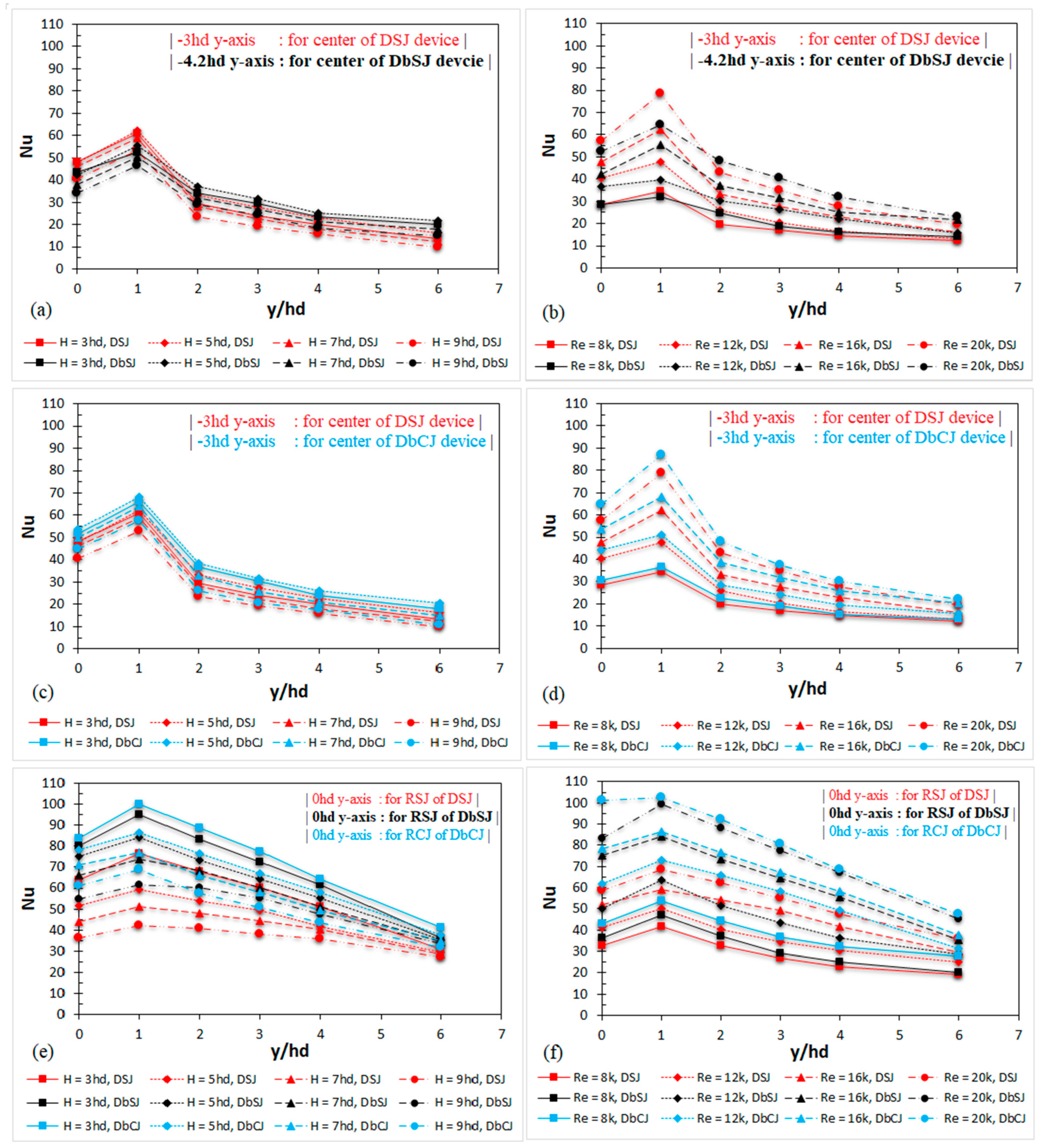
It is evident from the discussion of Figure 5 and Figure 6 that DbCJ dominates the central region of the Nusselt profiles while DSJ and DbSJ dominate the outer regions for all jet-to-wall spacings (3 hd, 5 hd, 7 hd, and 9 hd) and especially at higher Re numbers (8 k, 12 k, 16 k, and 20 k). Secondly, these trends were found to be more dominant at lower H and higher Re numbers. Therefore, the flow rate of Re = 16 k was chosen to analyze the effects of various jet-to-wall spacings (3 hd, 5 hd, 7 hd, and 9 hd) on the Nusselt profiles of the DSJ, DbSJ, and DbCJ in the transverse direction—as shown in Figure 7a,c,e. Similarly, jet-to-wall spacing of H = 5 hd was selected to present the effects of varying Re numbers (8 k, 12 k, 16 k, 20 k) on Nusselt profiles of DSJ, DbSJ, and DbCJ in transverse direction—as shown in Figure 7b,d,f. Three y-axes were selected for the transverse direction analyses of the fluidic devices, i.e., 0 hd y-axis, −3 hd y-axis, and −4.2 hd y-axis. At the 0 hd y-axis, the right jets of all fluidic devices are aligned; therefore, the DSJ, DbSJ, and DbCJ were mutually compared—as shown in Figure 7e,f. At the −3 hd y-axis, centers of the DSJ and DbCJ devices are aligned and hence got compared successfully—shown in Figure 7c,d. At −4.2 hd y-axis, only center of the DbSJ device is aligned; therefore, it was compared with 3 hd y-axis for the DSJ—as shown in Figure 7a,b.
It can be seen from Figure 7a that DSJ is better than DbSJ for all jet-to-wall spacings in the region from 0 hd to 2 hd; after 2 hd location, DbSJ dominates. A similar trend is observed in Figure 7b, where DSJ is better than DbSJ for all cases of Re numbers in a region from 0 hd to 2 hd; after 2 hd, the DbSJ performance revives and supersedes that of DSJ up to 6 hd. It is due to the fact, that DSJ is good in the core region of impingement while DbSJ is better in the outer region of transverse direction. It was also noted from these two figures (a and b) that Nusselt profiles increased with decreasing the distance and increasing Re number for both the DSJ and DbSJ. The divergent behavior found in Figure 7a is for both the DSJ and DbSJ; these two jets at H = 3 hd did not behave better than the 5 hd distance as expected. This is due to the fact that at the narrowest distance, the flow rate is more directed along the sweeping direction, and hence, little is available to divert in the transverse direction. Figure 7c shows that the heat removal performance of the DSJ is less than that of the DbCJ for all jet-to-wall spacings and for the entire domain ranging from 0 hd to 6 hd. The same is true for Figure 7d, where DSJ performs less than DbCJ for all Re numbers and along the entire y-axis. This phenomenon is attributed to the strong core of DbCJ, which is far better than that of DSJ. It was also noted from these two figures (c and d) that the Nusselt profiles increased with decreasing distance and increasing Re number for both the DSJ and DbCJ. The divergent behavior found in Figure 7c is for both the DSJ and DbCJ; these two jets at H = 3 hd did not behave better than 5 hd as expected. This anomaly is justifiable for DbCJ, since it was observed before as well (Section 3.1) that DbCJ possesses better potential at moderate distances (>3 hd). However, for DSJ, this anomaly is difficult to digest as DSJ is reputed for smaller distances and higher Re number (both conditions are being met here)—the only plausible explanation is that flow is directed more along the sweeping direction than to the transverse direction. Finally, at 0 hd y-axis DbCJ behaves better than both the DSJ and DbSJ in terms of jet-to-wall spacing, as shown in Figure 7e. Likewise, DbCJ also behaves better than both of these fluidic devices for all Re numbers, as shown in Figure 7f. The DbSJ also performed better than the DSJ for all jet-to-wall spacings and Re numbers. Nonetheless, the Nusselt number difference between the DSJ and DbCJ was larger, while the DbSJ and DbCJ profiles were relatively closer. At the 0 hd y-axis, the Nusselt number profiles increased by reducing the distance and accelerating the flow to higher Re numbers for all DSJ, DbSJ, and DbCJ cases. Lastly, for all these fluidic devices, while cooling along the transverse direction, the best cooling is achieved at 1 hd and then smoothly drops away from the center.
It is vital to understand Figure 5 and Figure 7 together, as the same trends are repeated but with different connotations. Here, the mutual relationship of DbCJ, DbSJ, and DSJ in the transverse direction, as explained above, is the same as that noted along the sweeping direction and discussed in Section 3.1. There, it was concluded that at 0 hd DbCJ > DbSJ > DSJ; at −3 hd DbCJ > DSJ; and at −4.2 hd DSJ > DbSJ—and the same trends can be observed here in Figure 7e, Figure 7c, Figure 7a or Figure 7f, Figure 7d, Figure 7b respectively. Therefore, the trends are simply extended in the transverse direction, strengthening the reasons for the dominance of one device over the other at these particular points. At 0 hd, DbCJ is strongest while DSJ is weakest since each of its throats is sharing its fluid volume with the neighboring throat to keep the jets synchronized; while each of DbCJ or DbSJ throat is independent and relatively stronger than DSJ. Similarly, at −3 hd, the DbCJ is better than DSJ because the effects of their respective cores have extended up to this point and established the same relationship as was found at 0 hd. Moreover, the center of the DbSJ device at −4.2 hd is much farther away from its core than the respective center of the DSJ device at −3 hd. Additionally, the center of the DSJ device experienced more impingement by the sweeping jets than the center of the DbSJ because of the non-availability of synchronous behavior of sweeping jets for the latter device. Therefore, the phenomenon at three y-axes of 0 hd, −3 hd, and −4.2 hd is a mere extension of the findings reported for the sweeping directions of the DSJ, DbSJ, and DbCJ.

3.3. Fluidic Devices’ Behavior at Various Aspect Ratios

To further investigate the behavior of the sweeping jets, two aspect ratios were selected: AR 1.20 (5.5 mm × 4.6 mm) and AR1.56 (6.4 mm × 4.1 mm), while maintaining the hydraulic diameter at 5 mm. These ARs were selected for the DSJ and DbSJ because of their square throats and for a detailed verification of the inherent benefits of these two different (synchronous and asynchronous) but sweeping jets. Therefore, further experiments were conducted for these four extra fluidic devices, DSJ 1.20, DSJ 1.56, DbSJ 1.20, and DbSJ 1.56, at Re = 8 k, 12 k, 16 k, and 20 k and jet-to-wall spacing, H = 3 hd, 5 hd, 7 hd, and 9 hd. In Figure 8, (a) and (b) demonstrate the behavior of both the DSJ and DbSJ with AR1.20 at different H and varying Re, respectively. Similarly, (c) and (d) demonstrate the behavior of both the DSJ and DbSJ with AR1.56 at different H and varying Re, respectively. Lastly, (e) and (f) represent a comparison of AR1.0, AR1.20 and AR1.56 for DSJ and DbSJ, respectively. Parts (e) and (f) are not placed in the same diagram as the comparison of DSJ vs. DbSJ for AR1.0 has already been presented and discussed in Section 3.1, and the remaining comparison of DSJ vs. DbSJ for AR1.20 and AR1.56 is given in Figure 8 parts (a), (b), (c), and (d). Again, Re = 16 k and H = 5 hd were selected for the same reason as presented in Section 3.2.

3.3.1. Regional Effects

The pointwise behaviors of DSJ and DbSJ are identical to each other, and the same is true for AR1.20 and AR1.56, as shown in Figure 8a–d. Reportedly, both fluidic devices perform better at −1 hd than at the sharp-core 0 hd, and their performance at 1 hd is further better than both at 0 hd and 1 hd. Their better performance at 0 hd in comparison to −1 hd and 1 hd owes its reasons as reported by Zhou et al. [28] and Lundgreen et al. [42], and discussed in Section 3.1. The fact that 1 hd has a higher Nusselt number than −1 hd is due to the situation at positions 2 hd and −2 hd. Since the fall at 2 hd was seen as bigger than that at −2 hd, therefore it is reasonable to conclude that the flow rate gets accumulated more at 1 hd than at −1 hd. Secondly, this cause-effect relationship is further strengthened by the fact that the left region (−2 hd to −4.2 hd) also receives flowrate from the left sweeping jet (LSJ) as well as from the right sweeping jet (RSJ), and hence −1 hd does not deplete point −2 hd much and falls slightly shorter in performance than 1 hd. Thirdly, it is also interesting to note from (a), (b), (c), and (d) parts of Figure 8, for various Re and different H, that the fall of profiles at −2 hd and 2 hd is not as sharp as was seen in Figure 5 and Figure 6, for all ranges of Re and H—and this is because aspect ratio has been increased from 1.0 to 1.20 and 1.56. A higher aspect ratio implies that the device is more elongated at its throat and shrunken for its depth; therefore, it pushes the flow volume more along the sweeping direction, and points like −2 hd and 2 hd receive more cool air to further cool the surface. For the region after 2 hd, profiles of DSJ and DbSJ drop smoothly for all Re numbers, all jet-to-wall spacings, and both aspect ratios. For the region before −2 hd, profiles of DSJ rise to −3 hd for all cases of Re and H; while conversely, the profiles of DbSJ dip smoothly further up to −4.2 hd for all cases of Re and jet-to-wall spacing.

3.3.2. Effects of Re Number and Jet-to-Wall Spacing Variations

Figure 8a shows that the Nusselt number increased with decreasing H for all regions of the profiles (left, central, and right) and for both the DSJ and DbSJ. Additionally, a uniform rise was observed for all regions of profiles of DSJ when spacing was increased gradually, while DbSJ showed a substantial rise in Nusselt numbers for 3 hd and 5 hd jet-to-wall spacings, especially in the central region. This is because the DbSJ cores for the left and right sweeping jets are separate from each other and hence are stronger than the respective throats of the DSJ. This reasoning would also govern the comparative behavior of the DSJ and DbSJ in the region from 2 hd to 9 hd of profiles in the succeeding section. Figure 8b shows an increase in the Nusselt number with an increase in the Re number for both the DSJ and DbSJ and all regions. It also reports a uniform rate of increase with Re variations for DbSJ for all of its profiles’ regions but provided a substantial increase for profiles of DSJ at higher Re numbers (16 k, 20 k) for all of its profiles regions. The preceding discussion of the two figures determined the behavior of devices with AR1.20, and the succeeding discussion of the two figures is for the same devices (DSJ, DbSJ) but with AR1.56. Figure 8c shows the profiles of both DSJ and DbSJ rising in the Nusselt number by reducing the jet-to-wall spacing, H, and uniformly for all regions of the profiles.
Additionally, a substantial drop in the Nusselt number was observed for all regions of the DSJ and DbSJ when the distance-rise crossed from 7 hd to 9 hd, indicating that both devices are effective at lower distances and their performance decreases significantly at very high jet-to-wall spacings. Figure 8d shows the rising profiles of both DSJ and DbSJ with increasing Re numbers (8 k to 20 k) for their left, central, and right regions. Although the rate of increase of profiles between 8 k and 20 k Re is uniform for all regions of both DSJ and DbSJ, aggressive behavior is noted for DSJ at 20 k.

3.3.3. Comparison of DSJ vs. DbSJ

From Figure 8a, it is evident that DSJ performs less than DbSJ in the central region (−1 hd to 1 hd) and better in the right region (2 hd to 9 hd) for all jet-to-wall spacings. In the left region (−4.2 hd to −2 hd), DSJ also shows better heat removal potential than DbSJ for all H when points −4.2 hd and −3 hd are compared for DbSJ and DSJ, respectively. It is also worth noting that the difference between DSJ and DbSJ is considerable for higher jet-to-wall spacings. The same results for DSJ and DbSJ can also be deduced from Figure 8b, but here, for all Re numbers, the difference between DSJ and DbSJ is greater at higher Re numbers. This means that out of DSJ and DbSJ with AR1.20, the DSJ is more usable in the outer regions, while DbSJ is effective in the inner region along the sweeping motion of the jets. This is because the shared sweeping jets of the DSJ divert the flow more sideways, and the separated sweeping jets of the DbSJ hold two stronger cores at each throat exit. Therefore, the center of the DSJ deteriorates more rigorously than that of the DbSJ at high jet-to-wall spacings and higher Re numbers, while holding the outer regions more efficiently under similar conditions. The exact patterns can be observed in Figure 8c and d for the DSJ and DbSJ with AR1.56; hence, the same reasoning holds for the DSJ and DbSJ with AR1.56.

3.3.4. Comparison of Aspect Ratios

Henceforth, we discuss the individual behavior of sweeping jets produced by DSJ and DbSJ fluidic devices with aspect ratio 1.0 in Section 3.1 and with aspect ratios 1.20 and 1.56 in Section 3.3. In Figure 8e,f, separate comparisons are drawn for DSJ and DbSJ, respectively, while keeping Re at 16 k and jet-to-wall spacing at 5 hd. Both of these figures mutually compare AR1.0, AR1.20, and AR1.56 for DSJ and DbSJ separately. Figure 8e shows that the Nusselt number profiles of AR1.20 and AR1.56 are better than that of AR1.0 for all regions, i.e, left, central, and right. Of AR1.20 and AR1.56, the former performed well in the left and central regions, whereas the latter was more effective in the right region. This relative heat removal performance of AR1.0, AR1.20, and AR1.56 once again highlights the importance of having a ‘strong core’—even here, purely for the DSJ cases. As previously found and discussed, the DbCJ had a better core than DSJ and DbSJ; the DbSJ was better than DSJ at its core; and similarly, here for DSJ, the AR1.0 retained a better core than AR1.20 and AR1.56. Next, from Figure 8f, it can be seen that AR1.20 is better than AR1.0 for all profile regions of DbSJ (ignoring its behavior at 9 hd on the x-axis since no such deviancy was observed at any of the other locations or profiles). AR1.56 performed better than AR1.0 and AR1.20 in the right region and in the left region, where AR1.56 was smaller than the other two aspect ratio profiles first and then increased slowly to cross them over at −4.2 hd. Finally, in the central region, AR1.56 was found to be much smaller than the other two aspect ratios, 1.0 and 1.20, of DbSJ. The better performance of AR1.20 in comparison to AR1.0 and the superior heat removal of AR1.56 in relation to AR1.0 and AR1.20 can be attributed to the fact that the former are more elongated and thinner than the latter. In addition, it is convenient to conclude from Figure 8e that the Nu profiles of the DSJ improved once the throats were squeezed for a higher aspect ratio of 1.20. This availability of a higher flow volume at the core and in the surroundings came at the cost of depletion in the transverse direction. The Nu number data of the DSJ at higher AR ratios in the transverse direction showed depletion but could not be presented here since it is reasonable to assume that this kind of behavior occurs once the throat of the jet becomes elongated. It is also reasonable to assume that this squeezing effect would have some limitations, which can be observed from the profile of the DSJ at an aspect ratio of 1.56. The surrounding area now receives a higher flow volume, but at the cost of the core. The same pattern can be noted from the Nu number profiles of DbSJ, for Figure 8f, at higher aspect ratios. However, for the DbSJ, two separate throats are at work without any means to support each other (in contrast to the DSJ); therefore, once the throat is squeezed or elongated (AR1.20), a slight improvement occurres in all regions, although a similar depletion in the transverse direction is observed here as well. At a higher aspect ratio of 1.56, a noticeable improvement in the outer region occurred once again at the cost of core depletion. Because the core is alone, the drop at the core is more noticeable than it was for the DSJ. The effect of changing the aspect ratios was also studied by Agricola et al. [43] and Hossain et al. [44] for aspect ratios smaller than unity. In particular, Agricola et al. [43] maintained the same hydraulic diameter and compared AR1.0 with AR0.5; they determined that AR0.5 enhanced heat transfer in the off-axis direction because AR0.5 thickened the device in the off-axis direction. Similarly, Hossain et al. [44] tested aspect ratios of 0.5, 0.75, and 1.0 and reported that the best results were obtained with an aspect ratio of unity (the largest one). The results found and discussed in this study match those of the referenced studies and report the effects of increasing the aspect ratio from AR1.0 to AR1.20 and AR1.56 in Figure 8e and Figure 8f, respectively.

4. Conclusions

This study experimentally evaluated the relative heat transfer performances of the DSJ, DbSJ, and DbCJ to determine their extent of usability in multi-jet configurations and achieve uniform cooling. The jets produced by these fluidic devices were impinged perpendicularly on a flat hot bed pasted with thermocouples to record the time-averaged heat transfer. The fluidic oscillators were tested for various jet-to-wall spacings, i.e., 3 hd, 5 hd, 7 hd, and 9 hd and at different Re numbers, i.e., 8 k, 12 k, 16 k, and 20 k. The effects of changing the aspect ratios of these devices were also evaluated; hence, three aspect ratios were used for the DSJ and DbSJ, i.e., AR1.0, AR1.20, and AR1.56. The results obtained were discussed in terms of analyzing fluidic device behavior along the sweeping direction, in the transverse direction, and for different aspect ratios.
In summary:
  • The Nu number decreased with increasing jet-to-wall spacing and increased with increasing Re numbers for all devices.
  • The heat transfer rate is primarily a function of wall local temperature (Tw) and can be represented by the Nu number. Therefore, regions with higher Nu experience a significant drop in local temperature as a result of forced convection between the impinging cool air and heated impinged surface, and vice versa.
  • The regional analysis of different devices determined that the central core received the greatest heat transfer, and the surroundings experienced sharp drops; similar trends were reported by Van Hout et al. [45] and Raizner et al. [46] for circular steady jets.
  • However, the relative comparison showed that DSJ had the best performance at smaller spacing and higher Re, DbSJ had the best performance at moderate spacing and lower Re, and DbCJ had the best performance at moderate spacing and moderate Re.
  • The DbCJ is more effective at its core and should be used in industrial applications where the surroundings are well covered by other jets or are of least concern.
  • The DbSJ and DSJ are effective in covering larger areas and uniform cooling—especially the DSJ which dominates the area between the two consecutive jets (left region) and outer right region, especially at higher Re numbers.
  • The same findings apply to devices with a higher aspect ratio, where DSJ is better than DbSJ in the outer regions. The increase in aspect ratio resulted in the availability of more fluid volume in the outer regions and reduced the difference between the inner and outer regions for all profiles.
This study concludes that using a dual sweeping impinging jet is beneficial for the uniform cooling of a targeted flat surface. This device possesses the inherent advantage of covering the region between two consecutive devices more efficiently and without compromising its performance for far-surroundings. To achieve further benefits, it is recommended to use devices with a high aspect ratio. The authors feel the need to further evaluate the effects of aspect ratios smaller than unity and the impingement of this dual sweeping jet on curved or inclined surfaces.

Author Contributions

Conceptualization, M.Z.; Data curation, M.Z.; Formal analysis, F.R.; Funding acquisition, X.W.; Investigation, M.Z.; Methodology, M.Z.; Project administration, X.W.; Resources, M.Z.; Software, F.R.; Supervision, X.W.; Validation, F.R.; Visualization, M.Z.; Writing—original draft, M.Z.; Writing—review and editing, M.Z. All authors have read and agreed to the published version of this manuscript.

Funding

The authors gratefully acknowledge the financial support provided by the National Natural Science Foundation of China (grant nos. 12072196 and 12227803).

Data Availability Statement

The data presented in this study are available on request from the corresponding author due to privacy.

Conflicts of Interest

The authors declare that they have no known competing financial interests or personal relationships that could have appeared to influence the work reported in this paper.

Nomenclature and Glossary

Nomenclature
AArea (m2)PPower (W), V/I
ARAspect ratio, tw/tdPLAPoly-Lactic Acid
CCelsiusqHeat flux rate (W/m2)
DbCJDouble circular jetsQHeat transfer rate (J/s or W), kA/LdT
DbSJDouble sweeping jetsReReynolds number, ρVtL/μ
DSJDual sweeping jetRCJRight circular jet
dTTemperature differential (K)RSJRight sweeping jet
Fig.FiguresSecond
hheat transfer coefficient (W/m2K), q/dTSCJSingle circular jet
HJet-to-wall spacing (m)SLPMStandard liter per minute
hdHydraulic diameter (m), 4A/PTTemperature (K)
ICurrent (A)TadbAdiabatic temperature (K)
JJouleTCsThermocouples
KKelvintdThroat depth (m)
kgKilogramTwFlat surface wall temperature (K)
LCharacteristic length (m)twThroat width (m)
LCJLeft circular jetVVolt (V)
LPMLiter per minuteVtThroat velocity (m/s)
LSJLeft sweeping jetWWatt
mMeterx-axissweeping direction of flow
mfrMass flow rate (kg/s), ρVAy-axisperpendicular to the sweeping motion
NuNusselt number, qhd/kdTz-axisflow impingement direction
pPerimeter (m)
Greek Symbols
ρDensity (kg/m3)Subscripts
kThermal conductivity (W/mK)adbAdiabatic
μDynamic viscosity (kg/ms)tThroat
νKinematic viscosity (m2/s)wWall
Glossary
Adiabatic temperaturetemperature of the targeted wall before impingement and heating the surface
Aspect ratiothe ratio of the throat’s width to depth is called the aspect ratio
Circular jeta device with a circular tube, for the most part of its length, to stabilize and impinge the injected fluid at the targeted surface
Divergent anglethe angle formed by the exit walls of the device is called a divergent angle since it helps the flow diverge in a smooth manner
Double circular jeta device with two circular tubes, each with a separate inlet, and a wall in between them
Double sweeping jeta device that housed two fluidic oscillators without any fluid-sharing mechanism and a wall in between them
Dual sweeping jeta special device designed by fusing two fluidic oscillators in a single housing and by sharing the nearest feedback channel of each fluidic oscillator
Dwelling timethe time the sweeping jet spends at one place, inside the fluidic oscillator, before switching to the opposite side is called dwelling time
Feedback channela passage inside a fluidic oscillator that helps send fluid back to the upcoming fluid
Flow field2D or 3D space of discretized fluid showing density, velocity, and pressure measurements at each node of an element
Fluidic oscillatora device with no moving parts that generates oscillating fluid side-to-side both internally and externally
Heat transfer enhancementa mechanism in which heat is transferred to/from the target surface with the help of a hot or cool stream of fluid
Hydraulic diameterhydraulic diameter is used for non-circular channels to transform them into pipes of equivalent diameter
Impingementa technique of heat transfer in which hot or cold fluid is targeted at the heated or cooled surface for heat transfer enhancement
Impingement directionthe streamwise direction of flow
Jet-to-wall spacinga measure of the distance between the targeted surface and the device’s throat
Nusselt numberit is a ratio of convective heat transfer to conductive heat transfer and hence provides relative effectiveness of convection
Reynolds numberit is a ratio of inertial forces to the viscous forces. It is used for understanding the viscosity effects and hence the classification of fluids into laminar and turbulent
Stagnation regionthe region where fluid streams hit the targeted surface
Steady jeta fluidic jet that does not fluctuate or change its behavior with time
Sweeping directionthe direction in which the oscillating flow oscillates
Sweeping jetan unsteady jet that changes its direction, dynamic behavior, and thermal properties with time
Switching timethe time sweeping jet takes commuting from one island to the other, inside the fluidic oscillator, is called switching time
Thermal bathit is a mechanism to heat the compressed air at a constant temperature by heating the copper coiling dipped in water bath-tub
Thermal field2D or 3D space of discretized fluid showing temperature measurements at each node of an element
Throatthroat is the exit point of a device after which the fluid gets exposed to the environment
Throat velocityarea-averaged velocity at each throat
Transverse directionthe direction perpendicular to the sweeping direction
Wall temperaturetemperature of the targeted wall after heated at constant flux for a sufficient amount of time

References

  1. Zuckerman, N.; Lior, N. Jet Impingement Heat Transfer: Physics, Correlations, and Numerical Modeling. Adv. Heat Transf. 2006, 39, 565–631. [Google Scholar]
  2. Liu, R.; Wei, W.; Wan, H.; Lin, Q.; Li, F.; Tang, K. Experimental Study on Airfoil Flow Separation Control via an Air-Supplement Plasma Synthetic Jet. Adv. In Aerodyn. 2022, 1, 34. [Google Scholar] [CrossRef]
  3. Hao, L.; Hu, B.; Gao, Y.; Wei, B. Effect of Vortex Generator Spanwise Height Distribution Pattern on Aerodynamic Characteristics of a Straight Wing. Adv. In Aerodyn. 2023, 1, 4. [Google Scholar] [CrossRef]
  4. Wilson, D.I.; Atkinson, P.; Köhler, H.; Mauermann, M.; Stoye, H.; Suddaby, K.; Wang, T.; Davidson, J.F.; Majschak, J.P. Cleaning of Soft-Solid Soil Layers on Vertical and Horizontal Surfaces by Stationary Coherent Impinging Liquid Jets. Chem. Eng. Sci. 2014, 109, 183–196. [Google Scholar] [CrossRef]
  5. Wang, H.; Yu, W.; Cai, Q. Experimental Study of Heat Transfer Coefficient on Hot Steel Plate During Water Jet Impingement Cooling. J. Mater. Process. Technol. 2012, 212, 1825–1831. [Google Scholar] [CrossRef]
  6. Laroche, E.; Fenot, M.; Dorignac, E.; Vuillerme, J.; Brizzi, L.E.; Larroya, J.C. A Combined Experimental and Numerical Investigation of the Flow and Heat Transfer Inside a Turbine Vane Cooled by Jet Impingement. J. Turbomach. 2017, 140, 031002. [Google Scholar] [CrossRef]
  7. Attalla, M.; Maghrabie, H.M.; Qayyum, A.; Al-Hasnawi, A.G.; Specht, E. Influence of the Nozzle Shape on Heat Transfer Uniformity for In-Line Array of Impinging Air Jets. Appl. Therm. Eng. 2017, 120, 160–169. [Google Scholar] [CrossRef]
  8. Lutum, E.; Johnson, B.V. Influence of the Hole Length to Diameter Ratio on Film Cooling with Cylindrical Holes. J. Turbomach. 1998, 121, 209–216. [Google Scholar] [CrossRef]
  9. Kohli, A.; Bogard, D.G. Effects of Very High Freestream Turbulence on the Jet-Mainstream Interaction in a Film Cooling Flow. J. Turbomach. 1998, 120, 785–790. [Google Scholar] [CrossRef]
  10. Zhou, Y.; Lin, G.; Bu, X.; Bai, L.; Wen, L. Experimental Study of Curvature Effects on Jet Impingement Heat Transfer on Concave Surfaces. Chin. J. Aeronaut. 2017, 30, 586–594. [Google Scholar] [CrossRef]
  11. Forouzanmehr, M.; Shariatmadar, H.; Kowsary, F.; Ashjaee, M. Achieving Heat Flux Uniformity using an Optimal Arrangement of Impinging Jet Arrays. J. Heat Transf. 2015, 137, 061002. [Google Scholar] [CrossRef]
  12. Goldstein, R.; Behbahani, A.I. Impingement of a Circular Jet with and without Crossflow. Int. J. Heat Mass Transf. 1982, 25, 1377–1382. [Google Scholar] [CrossRef]
  13. Carlomagno, G.M.; Ianiro, A. Thermo-Fluid-Dynamics of Submerged Jets Impinging at Short Nozzle-to-Plate Distance: A Review. Exp. Therm. Fluid Sci. 2014, 58, 15–35. [Google Scholar]
  14. Burns, A. Turbine Tip Clearance Control Using Fluidic Oscillator. Ph.D. Thesis, University of Kansas, Lawrence, KS, USA, 2015. [Google Scholar]
  15. Guyot, D.; Paschereit, C.O.; Raghu, S. Active Combustion Control Using a Fluidic Oscillator for Asymmetric Fuel Flow Modulation. Int. J. Flow Control 2009, 1, 155–166. [Google Scholar] [CrossRef]
  16. Tewes, P.; Taubert, L.; Wygnanski, I.J. On the Use of Sweeping Jets to Augment the Lift of a Lambda-Wing. In Proceedings of the 28th AIAA Applied Aerodynamics Conference, Chicago, IL, USA, 28 June–1 July 2010. [Google Scholar]
  17. Schmidt, H.J.; Nayeri, C.N.; Pashereit, C.O. Fluidic Oscillators for Bluff Body Drag Reduction in Water. In Proceedings of the 54th AIAA Aerospace Science Meeting, San Diego, CA, USA, 4–8 January 2016. [Google Scholar]
  18. Raman, G.; Raghu, S. Miniature Fluidic Oscillator for Flow and Noise Control–Transitioning from Macro to Micro Fluidics. In Proceedings of the Fluids Conference and Exhibition, Denver, CO, USA, 19–22 June 2000. [Google Scholar]
  19. Shamloo, A.; Vatankhah, P.; Bijarchi, M.A. Numerical Optimization and Inverse Study of a Microfluidic Device for Blood Plasma Separation. Eur. J. Mech. B: Fluids 2016, 57, 31–39. [Google Scholar] [CrossRef]
  20. Hanotu, J.; Bandulasena, H.C.H.; Chiu, T.Y.; Zimmerman, W.B. Oil Emulsion Separation with Fluidic Oscillator Generated Microbubbles. Int. J. Multiph. Flow 2013, 56, 119–125. [Google Scholar] [CrossRef]
  21. Woszidlo, R.; Ostermann, F.; Schmidt, H.J. Fundamental Properties of Fluidic Oscillators for Flow Control Applications. In Proceedings of the 57th AIAA Aerospace Science Conference, San Diego, CA, USA, 7–11 January 2019. [Google Scholar]
  22. Gregory, J.; Sullivan, J.P.; Raman, G.; Raghu, S. Characterization of a Micro Fluidic Oscillator for Flow Control. In Proceedings of the 2nd AIAA Flow Control Conference, Portland, OR, USA, 28 June–1 July 2004. [Google Scholar]
  23. Li, Z.; Zhou, K.; Liu, Y.; Wen, X. Jet Sweeping Angle Control by Fluidic Oscillators with Master-Slave Designs. Chin. J. Aeronaut. 2021, 34, 145–162. [Google Scholar] [CrossRef]
  24. Wen, X.; Li, Z.; Zhou, W.; Liu, Y. Interaction of Dual Sweeping Impinging Jets at Different Reynolds Numbers. Phys. Fluids 2018, 30, 105105. [Google Scholar] [CrossRef]
  25. Pandey, R.J.; Kim, K.Y. Numerical Modeling of Internal Flow in a Fluidic Oscillator. J. Mech. Sci. Technol. 2018, 32, 1041–1048. [Google Scholar] [CrossRef]
  26. Ostermann, F.; Woszidlo, R.; Nayeri, C.N.; Paschereit, C.O. Time-Resolved Flow Field of a Jet Emitted by a Fluidic Oscillator into a Crossflow. In Proceedings of the 54th AIAA Aerospace Science Meeting, San Diego, CA, USA, 4–8 January 2016. [Google Scholar]
  27. Kim, S.H.; Kim, H.D.; Kim, K.C. Measurement of Two-Dimensional Heat Transfer and Flow Characteristics of an Impinging Sweeping Jet. Int. J. Heat Mass Transf. 2019, 136, 415–426. [Google Scholar] [CrossRef]
  28. Zhou, W.; Yuan, L.; Liu, Y.; Peng, D.; Wen, X. Heat Transfer of a Sweeping Jet Impinging at Narrow Spacing. Exp. Therm. Fluid Sci. 2019, 103, 89–98. [Google Scholar] [CrossRef]
  29. Hossain, M.A.; Prenter, R.; Lundgreen, R.; Ameri, A.; Gregory, J.; Bons, J.P. Experimental and Numerical Investigation of Sweeping Jet Film Cooling. J. Turbomach. 2017, 140, 031009. [Google Scholar] [CrossRef]
  30. Joulaei, A.; Nili-Ahmadabadi, M.; Ha, M.Y. Numerical Study of the Effect of Geometric Scaling of a Fluidic Oscillator on the Heat Transfer and Frequency of Impinging Sweeping Jet. Appl. Therm. Eng. 2023, 221, 119848. [Google Scholar] [CrossRef]
  31. Park, T.; Kara, K.; Kim, D. Flow Structure and Heat Transfer of a Sweeping Jet Impinging on a Flat Wall. Int. J. Heat Mass Transf. 2018, 124, 920–928. [Google Scholar] [CrossRef]
  32. Kim, D.J.; Jeong, S.; Park, T.; Kim, D. Impinging Sweeping Jet and Convective Heat Transfer on Curved Surfaces. Int. J. Heat Fluid Flow 2019, 79, 108458. [Google Scholar] [CrossRef]
  33. Gomes, R.; Barbosa, F.V.; Teixeira, J.C.F. Flow Dynamics and Heat Transfer Analysis of a Sweeping Air Jet—An Experimental Approach. Int. J. Heat Mass Transf. 2024, 227, 125479. [Google Scholar] [CrossRef]
  34. Tomac, M.N.; Gregory, J.W. Phase-Synchronized Fluidic Oscillator Pair. AIAA J. 2019, 57, 670–681. [Google Scholar] [CrossRef]
  35. Tomac, M.N.; Gregory, J.W. Frequency-Synchronized Fluidic Oscillator Array. U.S. Patent No. 11,085,469 B2, 9 August 2021. [Google Scholar]
  36. Zubair, M.; Wen, X. Flow Characteristics of a Dual Sweeping Jet Impinging on a Flat Surface. Actuators 2025, 14, 101. [Google Scholar] [CrossRef]
  37. Eghtesad, A.; Mahmoudabadbozchelou, M.; Afshin, H. Heat Transfer Optimization of Twin Turbulent Sweeping Impinging Jets. Int. J. Therm. Sci. 2019, 146, 106064. [Google Scholar] [CrossRef]
  38. Sieber, M.; Ostermann, F.; Woszidlo, R.; Oberleithner, K.; Paschereit, C.O. Lagrangian Coherent Structures in the Flow Field of a Fluidic Oscillator. Phys. Rev. Fluids 2016, 1, 050509. [Google Scholar] [CrossRef]
  39. Stouffer, R.D. Oscillating Spray Device. U.S. Patent 4,151,955, 30 April 1979. [Google Scholar]
  40. Wen, X.; Liu, Y.; Tang, H. Unsteady Behavior of a Sweeping Jet: Time-Resolved Particle Image Velocimetry Measurements. Exp. Therm. Fluid Sci. 2018, 96, 111–127. [Google Scholar] [CrossRef]
  41. Wen, X.; Li, Z.; Zhou, L.; Yu, C.; Zubair, M.; Liu, Y.; Wang, S.; Liu, Y. Flow Dynamics of a Fluidic Oscillator with Internal Geometry Variations. Phys. Fluids 2020, 32, 075111. [Google Scholar] [CrossRef]
  42. Lundgreen, R.K.; Hossain, M.A.; Prenter, R.; Bons, J.P.; Gregory, J.; Ameri, A. Impingement Heat Transfer Characteristics of a Sweeping Jet. In Proceedings of the 55th AIAA Aerospace Meeting, Grapevine, TX, USA, 9–13 January 2017. [Google Scholar]
  43. Agricola, L.; Hossain, M.A.; Prenter, R.; Ludgreen, R. Impinging Sweeping Jet Heat Transfer. In Proceedings of the 53rd AIAA Joint Propulsion Conference, Atlanta, GA, USA, 10–12 July 2017. [Google Scholar]
  44. Hossain, M.A.; Agricola, L.M.; Ameri, A. Sweeping Jet Impingement Heat Transfer on Simulated Turbine Vane Leading Edge. J. Glob. Power Propuls. Soc. 2018, 2, 402–414. [Google Scholar] [CrossRef]
  45. Van Hout, R.; Rinsky, V.; Grobman, Y. Experimental Study of a Round Jet Impinging on a Flat Surface: Flow Field and Vortex Characteristics in the Wall Jet. Int. J. Heat Fluid Flow 2018, 70, 41–58. [Google Scholar] [CrossRef]
  46. Raizner, M.; Rinsky, V.; Grossman, G.; van Hout, R. The Effect of Jet Pulsation on the Flow Field of a Round Impinging Jet and the Radially Expanding Wall Jet. Int. J. Heat Mass Transf. 2019, 140, 606–619. [Google Scholar] [CrossRef]
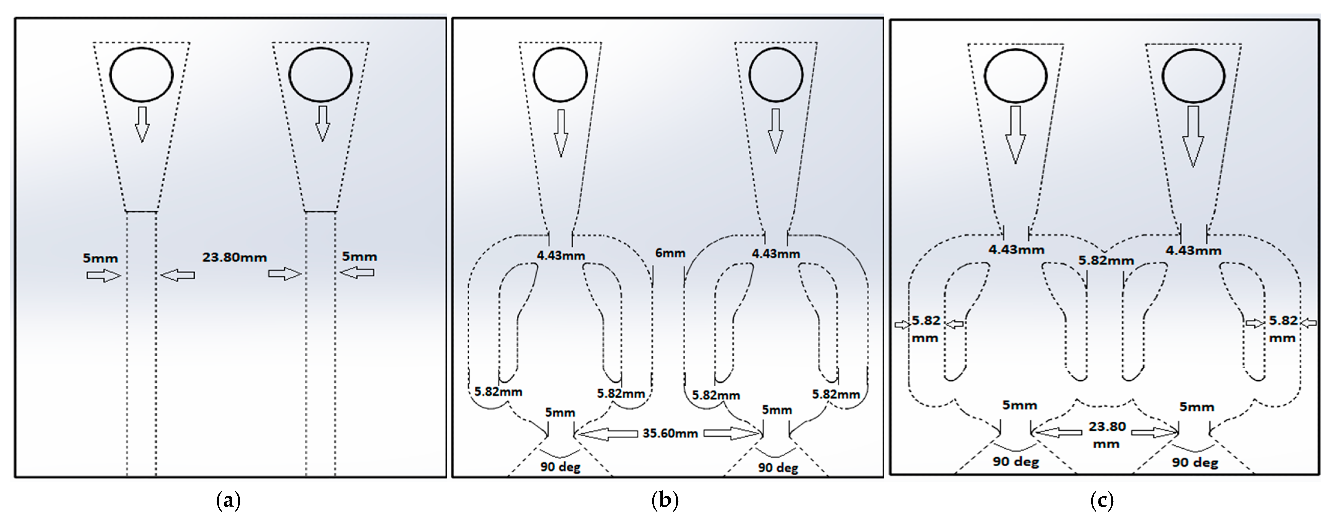
Figure 1. Different types of fluidic devices: (a) DbCJ—double circular jets, (b) DbSJ—double sweeping jets, and (c) DSJ—dual sweeping jet.
Actuators 14 00109 g001
Figure 2. Impingement setup for heat transfer measurements: (a) front view, (b) top view.
Actuators 14 00109 g002aActuators 14 00109 g002b
Figure 3. Overall experimental setup for the heat transfer measurements.
Actuators 14 00109 g003
Figure 4. Experimental methodology verification for a circular jet with hd = 5 mm (Kim et al. 2019 [27]).
Actuators 14 00109 g004
Figure 5. Comparison of Nusselt number profiles of DSJ, DbSJ, and DbCJ along the x-axis (sweeping direction) and for different Re numbers: (a) Re = 8 k, (b) Re = 12 k, (c) Re = 16 k, (d) Re = 20 k.
Actuators 14 00109 g005
Figure 6. Comparison of Nusselt number profiles of DSJ, DbSJ, and DbCJ along the x-axis (sweeping direction) and for different jet-wall-spacings: (a) H = 3 hd, (b) H = 5 hd, (c) H = 7 hd, and (d) H = 9 hd.
Actuators 14 00109 g006
Figure 7. Comparison of Nusselt number profiles of DSJ, DbSJ, and DbCJ for different y-axes (transverse directions): (a) DSJ vs. DbSJ, at −3 hd and −4.2 hd y-axes respectively, Re = 16 k, different H; (b) DSJ vs. DbSJ, at −3 hd and −4.2 hd y-axes respectively, H = 5 hd, different Re; (c) DSJ vs. DbCJ, both at −3 hd y-axis, Re = 16 k, different H; (d) DSJ vs. DbCJ, both at −3 hd y-axis, H = 5 hd, different Re; (e) DSJ vs. DbSJ vs. DbCJ, all at 0 hd y-axis, Re = 16 k, different H; (f) DSJ vs. DbSJ vs. DbCJ, all at 0 hd y-axis, H = 5 hd, different Re.
Actuators 14 00109 g007
Figure 8. Comparison of Nusselt number profiles of DSJ and DbSJ for different aspect ratios along the x-axis (sweeping direction): (a) AR = 1.20, Re = 16 k, different H; (b) AR = 1.20, H = 5 hd, different Re; (c) AR = 1.56, Re = 16 k, different H; (d) AR = 1.56, H = 5 hd, different Re; (e) DSJ, Re = 16 k, H = 5 hd, different AR; (f) DbSJ, Re = 16 k, H = 5 hd, different AR.
Actuators 14 00109 g008
Disclaimer/Publisher’s Note: The statements, opinions and data contained in all publications are solely those of the individual author(s) and contributor(s) and not of MDPI and/or the editor(s). MDPI and/or the editor(s) disclaim responsibility for any injury to people or property resulting from any ideas, methods, instructions or products referred to in the content.