Abstract
As the field of robotics advances swiftly, industrial automation has become prevalent in the realms of manufacturing and precision measurement. In robot measurement applications, the original path often originates from the discrete output of CAD models or point cloud data of vision systems, and its measurement path is a linear path composed of discrete feature points. Vibrations are generated by robots when passing through corners between adjacent linear segments. In order to reduce vibration, an algorithm for smoothing the robot’s measurement path based on multiple curves is proposed. Based on the proposed robot scanning measurement path generation algorithm, a robot scanning measurement path is generated. The position and attitude of the scanning path are represented as multiple curves using a position and attitude representation method based on multiple curves. The corners of the position curve and attitude curve are smoothed using a 5th-order B-spline curve. Based on the established robot position tolerance and attitude tolerance constraints and geometric continuity, the control points of the B-spline curve are solved, and corresponding position corner smooth B-spline curves and attitude corner smooth B-spline curves are constructed. Based on the geometric continuity, we use B-spline curves to replace the transition parts of adjacent position corner points and adjacent attitude corner points in the scanning path and then achieve the synchronization of robot position and attitude by the common curve parameter method. Finally, the effectiveness of our proposed path smoothing algorithm was verified through robot joint tracking experiments and scanning measurement experiments.
1. Introduction
The extensive deployment of industrial robots in intricate manufacturing and precision measurement tasks has been driven by the swift progress in robotics technology. During the measurement process, a laser scanner is outfitted on the end effector of the industrial robot, allowing high-precision scans and measurements to be performed with remarkable accuracy. To enhance measurement accuracy, it is necessary for the robot to be equipped with a laser scanner and to execute precise contour movements along a planned trajectory. To achieve this precise contour motion, multiple sets of discrete linear segments are typically employed to approximate the curved profile. As the robot transitions through the corner points between these linear segments, fluctuations in velocity, acceleration, and jerk occur, leading to vibrations in the laser scanner, which can degrade measurement precision. To address these issues, it is essential to smooth the original path. Currently, mainstream robot manufacturers’ controllers integrate path smoothing functions; however, they do not provide users with the capability to set tolerances for both the original and smoothed paths tailored to specific tasks, thus failing to meet user requirements.
A large number of researchers have conducted research on path smoothing algorithms, mainly focusing on global path smoothing algorithms and local corner smoothing algorithms. Due to the difficulty of evaluating and controlling errors in global path smoothing algorithms, current path smoothing mainly focuses on local corner smoothing.
In industrial measurement scenarios, robotic paths typically originate from discretized outputs of CAD models (e.g., STL format) or point cloud data acquired by vision systems. These paths are essentially approximate trajectories composed of linear segments. This discretization represents an inherent characteristic of digital workflows rather than researchers’ subjective simplification strategies. The proposed methodology specifically addresses such engineering inputs, achieving kinematic optimization through local smoothing while preserving the topological structure of original paths.
Researchers have conducted in-depth research on the smoothing of local corner paths in robots. In [1], Yuen et al. proposed a local path smoothing algorithm in 2013, but the background of their proposed algorithm was based on the industrial environment at that time. With the emergence of precision machining, measurement (now requiring ≤0.01 mm), and high-speed handling (≥2 m/s) demands, higher requirements have been put forward for the tracking accuracy of robots. Therefore, it is necessary to study new local path smoothing algorithms to improve the tracking accuracy of robots. Sun et al. proposed a 6-degree-of-freedom robot path smoothing algorithm based on asymmetric finite impulse response filters in [2]. An algorithm for smoothing the path of a 6-degree-of-freedom robot, utilizing asymmetric finite impulse response filters, was proposed by Sun et al. as referenced in [2]. By analyzing the tractability of joints under different postures and adjusting the joint dynamic constraints, this algorithm requires complex parameter adjustments. In [3], a C3 continuous path corner smoothing algorithm for 6-degree-of-freedom robots was introduced by Yang et al. This method enhances tracking precision by smoothing the tool’s position directly within the workpiece’s coordinate system and then converting the position matrix into Euler angles for further smoothing, albeit at the cost of increased computational demands. In [4], Chen et al. introduced an approach that leverages the surface characteristics of the workpiece to identify pivotal feature points, which streamlines the B-spline curve fitting process for 6-degree-of-freedom robots and minimizes the quantity of superfluous points. However, this method may reduce the tracking accuracy of the path due to insufficient feature points. In [5], Peng et al. proposed a C3 continuous local corner smoothing method suitable for industrial robots, which used exponential coordinates to parameterize the tool direction and achieved position and attitude synchronization by sharing the same curve parameters but required separate control of position and attitude errors. In [6], He et al. proposed a method for C2 continuous trajectory smoothing and interpolation tailored for industrial SCARA robots, which generated smooth paths while satisfying C2 continuity, tolerance constraints, shape preservation, uniform parameterization and real-time performance. However, this method may not be applicable to other types of robots. In [7], Zhang et al. proposed a C3 continuous method for local trajectory smoothing and synchronization specifically designed for five-axis hybrid robotic systems., which improved the smoothness of joint motion through a synchronization method based on arc length parameterization. However, this method has a high computational complexity. In [8], Liu et al. proposed a singularity-free smoothing approach for tool paths in five-axis hybrid robotic applications., which smoothed joint motion by modifying some control points of B-spline curves near singular configurations. However, this method may not be applicable to other types of robots. In [9], Li et al. proposed a semi-analytical C2 continuous tool path smoothing method for five-axis hybrid robots, which used numerical algorithms to generate inserted B-spline curves. However, this method performed poorly in terms of path smoothness.
The above studies all used Euler angles or exponential coordinates to smooth the direction of the robot tools but failed to directly control the directional error before and after smoothing the robot end tools, which also increased the computational complexity to some extent.
Many researchers have conducted in-depth research on the smoothness of five-axis CNC machining paths. In [10], Chen et al. introduced a geometric algebra-based approach for smoothing C3 corners in five-axis linear machining paths, although it was computationally intensive. In [11], Xu et al. proposed an adaptive NURBS curve interpolation technique that incorporated smooth feed adjustments and incremental parameter compensation, which improved machining efficiency and accuracy, but the computational complexity of this method was relatively high. In [12], Tang et al. put forward an algorithm for smoothing path corners that utilizes dual-filter technology, which smoothed path corners by applying dual finite impulse response filters, but it may not be sufficient to completely suppress mechanical vibrations in some cases. In [13], Cheng et al. proposed an algorithm for smoothing corners between two symmetric fifth-order B-splines, maintaining C3 continuity throughout the path. The authors of [14] used two B-spline curves to describe the position and direction of tool corners, accurately controlling the positional and directional tolerances of the path, but lacked the ability to achieve nonlinear parameterization. In [15], Bi et al. employed a pair of cubic Bezier curves for corner smoothing in tool paths, ensuring both tangent and curvature continuity along the path. However, this algorithm was only applied to CNC machine tools. In [16], Tulsyan et al. proposed a smoothing technique tailored for five-axis CNC systems, integrating higher-degree polynomials to enhance the accuracy of tool positioning and orientation. Nonetheless, this methodology was specific to CNC applications. In [17], Yang et al. proposed a C3 continuity algorithm for five-axis CNC machining, smoothing corners by incorporating B-splines at key path points. However, this method has not yet been extended to industrial robotic applications. In [18], Huang et al. developed a C2 local path corner smoothing algorithm designed for real-time application in five-axis CNC machine tools, which smoothed the path corners using cubic B-spline curves. However, no corresponding research has been conducted on industrial robots. In [19], Li et al. developed a path corner smoothing algorithm that directly adjusted the translational speed of the tool position and the rotational angular speed of the tool attitude in the workpiece coordinate system, but it was also only applied to five-axis NC machining. In [20], Li et al. proposed a NURBS pre-interpolator for five-axis machining that can convert traditional linear paths into NURBS curves. In [21], a local tool path smoothing algorithm that leverages symmetric NURBS transition curves and forward-looking optimization techniques to address the issue of tangent and curvature discontinuities in linear tool paths at corners. The study was limited to five-axis CNC machine tools. In [22], Yang et al. achieved higher motion efficiency by constructing asymmetric Pythagorean hodograph (PH) splines to smooth corners, but with higher computational complexity. In [23], Li et al. introduced an overarching tool path smoothing algorithm utilizing B-spline curves, aimed at diminishing peak curvature and enhancing machining efficiency within the CNC machining process. This algorithm was only applicable to CNC machine tools. In [24], Du et al. proposed an analytical C3 continuous transition method that effectively controls the shape of transition curves by adjusting the weights of NURBS curves. This method was only applicable to specific machine tool machining scenarios. In [25], Dong et al. proposed an optimal curvature smoothing algorithm for unmanned aerial vehicles, which introduced Bezier curves to smooth path corners and ensure continuous curvature, but it was only applied to the path smoothing of unmanned aerial vehicles.
The above studies have focused only on CNC machine tools and have concentrated on five axes. Nevertheless, the kinematic properties of 6-axis industrial robots differ markedly from five-axis CNC machines. In a five-axis CNC setup, the tool orientation is influenced solely by two rotational axes, whereas a six-axis robot’s tool orientation is impacted by all six rotational axes. Consequently, the smoothing techniques applicable to five-axis CNC machinery are not directly transferable to six-axis industrial robotics. Therefore, we propose a scanning measurement path smoothing algorithm for the current 6-degree-of-freedom industrial robots.
The principal contributions encapsulated within this document are delineated below:
- (1)
- The robot scanning measurement path smoothing method based on multiple curves is proposed, which stores position and direction information in two line segments and smooths the corners of the position and direction line segments based on 5th-order B-spline curves;
- (2)
- the scanning measurement path is established through the method proposed for the generation of such paths for multi-line structured light robots;
- (3)
- the validation of the proposed algorithm’s performance is achieved through experiments conducted on the smoothing and measurement of scanning measurement paths.
The structure of the subsequent content in this paper is delineated as follows: The generation of robotic scanning measurement trajectories is introduced in the Section 2. The Section 3 delineates that the coordinates and orientation of the scanning measurement path are recorded within a coordinate system and that the corners of the path are refined using a fifth-order B-spline curve. The Section 4 outlines a synchronization technique for the scanning path’s position and direction, which employs identical curve parameters. Experiments on path corner smoothing and scanning measurements are detailed in the Section 5, which is aimed at validating the effectiveness and benefits of the proposed method. A summary of conclusions and future research prospects is provided in the Section 6.
2. Generation of Robot Scanning Measurement Path
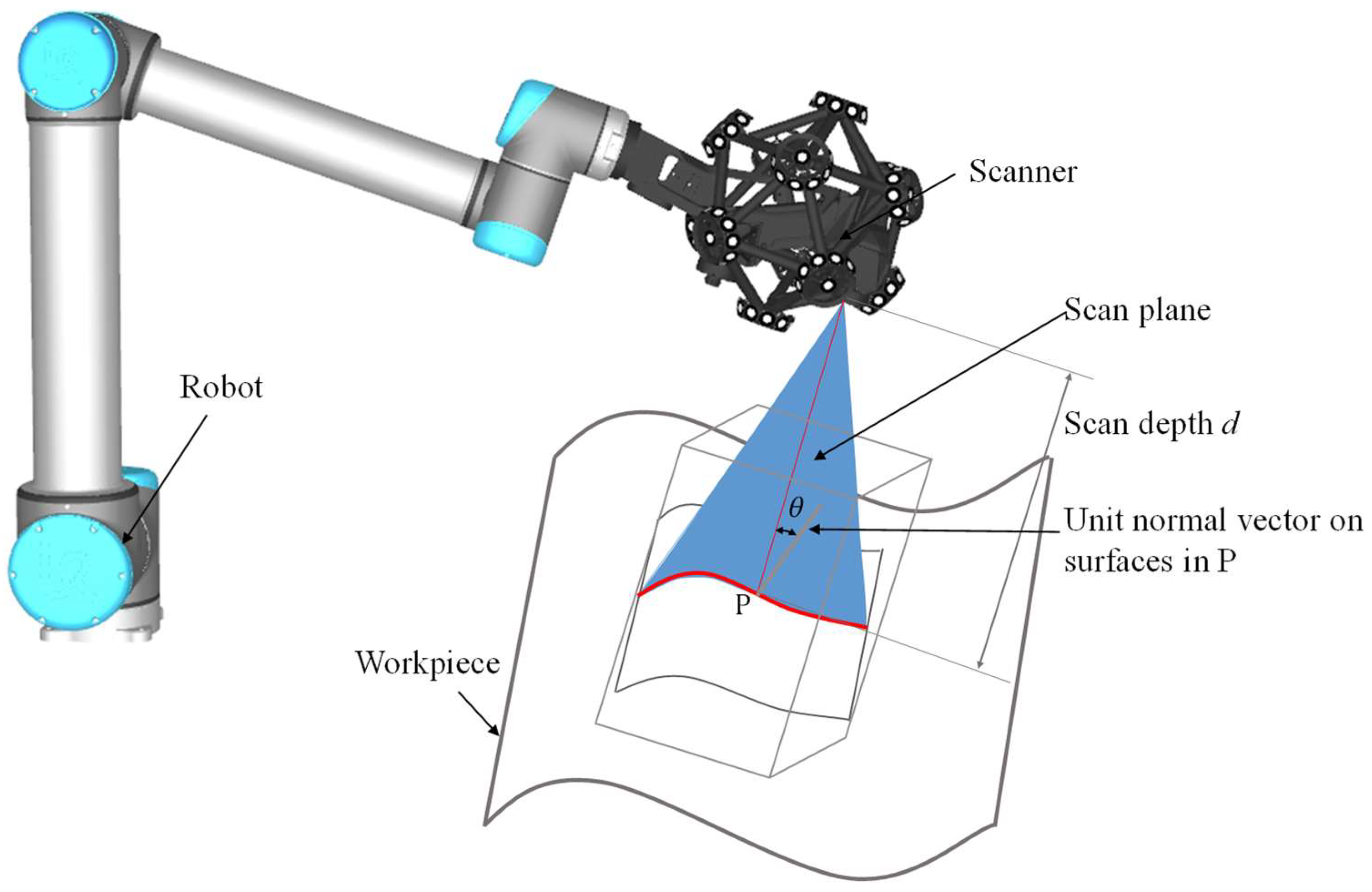
As shown in Figure 1, a laser beam is emitted by the laser scanner, reflected off the object under measurement, and then received by the camera. Given the known relative pose between the camera and the plane of light, the coordinates of the object can be determined. As referenced in the document [25], the precision of laser scanning is tied to the scanning angle and distance, specified as follows:
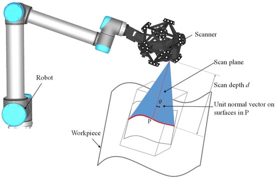
Figure 1.
Scanning measurement principle.
- (1)
- Measurement angle : is the angle between the laser beam emitted by the laser scanner and the normal vector at point P on the surface under measurement.
- (2)
- Measurement distance : is the distance between the laser scanner and the surface under measurement.
When the measurement angle and measurement distance between the laser scanner and the surface under measurement satisfy Equation (1), the measurement accuracy of the laser scanner is at its maximum.
where H is the optimal measurement distance for the laser scanner.
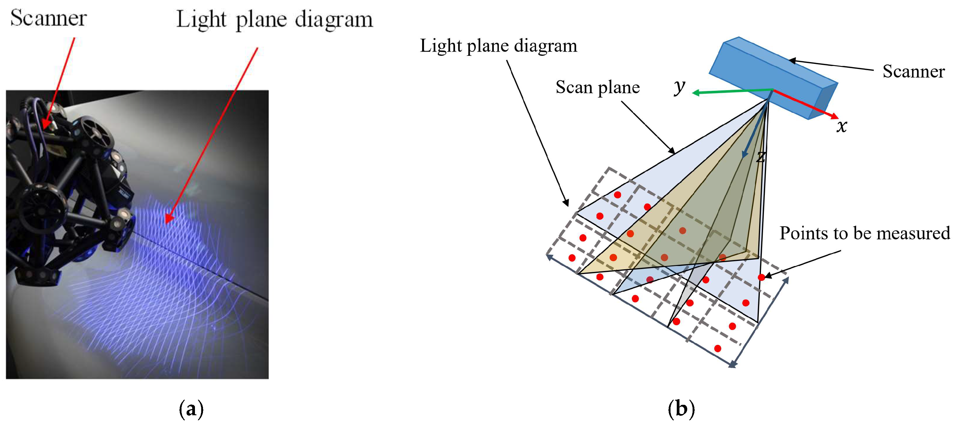
The laser scanner’s light plane is depicted in Figure 2b. In order to ensure the maximum measurement performance of the laser scanner, the multi-line structured light is equivalent to a rectangular area with fixed length and width values. The method we propose for generating robot scanning measurement paths is as follows:
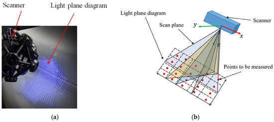
Figure 2.
Light plane of multi line laser scanner. (a) The figure shows the multi line laser emitted by the laser scanner. (b) The principle of equivalent multi line laser to a rectangular plane is shown in the figure.
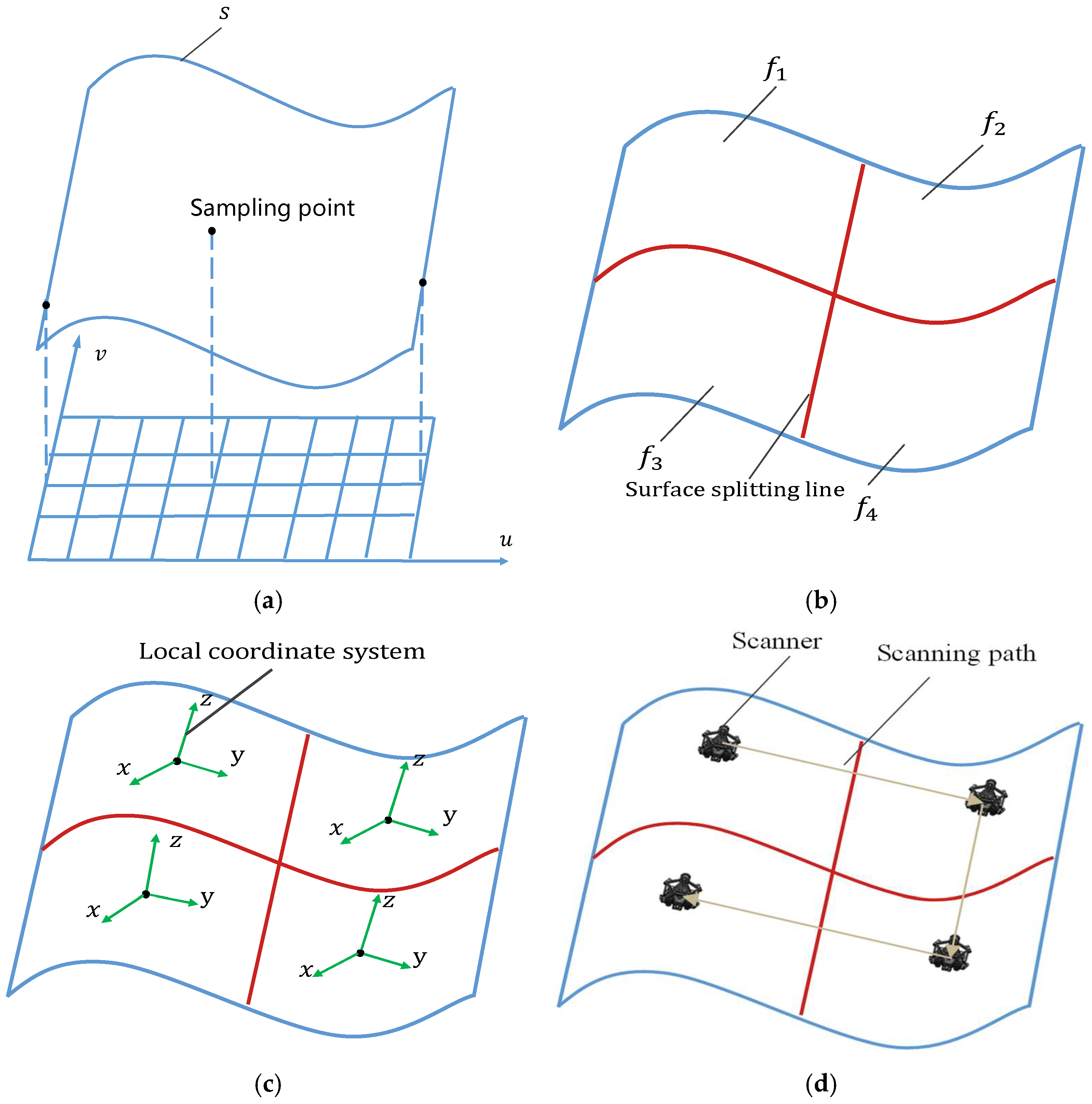
Step 1: As depicted in Figure 3a, facing the difficulty of directly segmenting the surface in the 3D parameter space, we reduce the surface’s dimensionality from the 3D to the 2D parameter space to simplify the partitioning process.
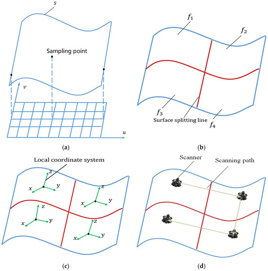
Figure 3.
Steps for generating scanning measurement paths. (a) Surface dimensionality reduction; (b) surface partitioning; (c) establishing local coordinate systems for each surface partition; (d) scanning measurement path generation.
Step 2: As depicted in Figure 3b, the number of surface blocks is ascertained based on the scanning area of the laser scanner. The two-dimensional parameter space is equally partitioned along the u and v parameters, following which the two-dimensional parameters are reassigned to the three-dimensional parameter space. The surface is divided into surface blocks based on the u and v parameters.
Step 3: As demonstrated in Figure 3c, for each surface block, a local coordinate system is set up with the z-axis pointing towards the normal vector at the block’s central point P, the x-axis following the v-direction at point P on the block, and the y-axis being perpendicular, determined by the cross product of the x and z vectors.
Step 4: Referencing Figure 3d, to maximize the laser scanner’s precision, we adjust H upwards along the z-axis of the local coordinate system for each surface block to find the ideal scanner placement. For each scanner, a coordinate system is established with the scanner’s location as the origin. The z-axis of this local system aligns with the z-axis direction, the line between the current and next scanner defines the x-axis direction, and the y-axis is determined by the cross product of the x and z vectors. These axes define the scanner’s orientation. By linking the optimal positions of the laser scanner for each surface block, the optimal scanning path determination is obtained.
As evident in Figure 3, the necessity for reciprocating motion along surface-parametric directions during multi-line structured light scanning inherently generates paths with dense directional transitions. When the scanning angle θ = 0° (Equation (1)), measurement accuracy reaches its theoretical maximum, forcing strict alignment of paths with surface normals. The laser plane’s effective projection forms a rectangular measurement area (see Figure 2b), necessitating specific angular continuity between adjacent scan paths to ensure data consistency. These constraints inevitably induce acute angles in robotic scanning trajectories.
3. Smooth Robot Scanning Measurement Path
Our research focuses on vibration suppression in precision measurement scenarios, contrasting with obstacle avoidance optimization in path planning. The robotic scanning path smoothing methodology herein establishes threefold objectives: maintaining controllable position error and orientation error, ensuring synchronization of measurement positions and orientations, and preserving C3 continuity in Cartesian space throughout scanning trajectories.
Compared to global continuous path smoothing, the segmented path smoothing approach demonstrates threefold advantages:
- (a)
- Computational efficiency: Only 5–10% of high-curvature regions require processing;
- (b)
- dynamic adaptability: Enables local path updates during online measurement operations;
- (c)
- industrial compatibility: Maintains native support for mainstream robotic G-code instruction sets, thereby preserving the existing CAM-to-controller technical ecosystem.
Therefore, we choose the segmented path smoothing method to smooth the robot scanning measurement path generated in the Section 2.
3.1. Spatial Pose Representation Method
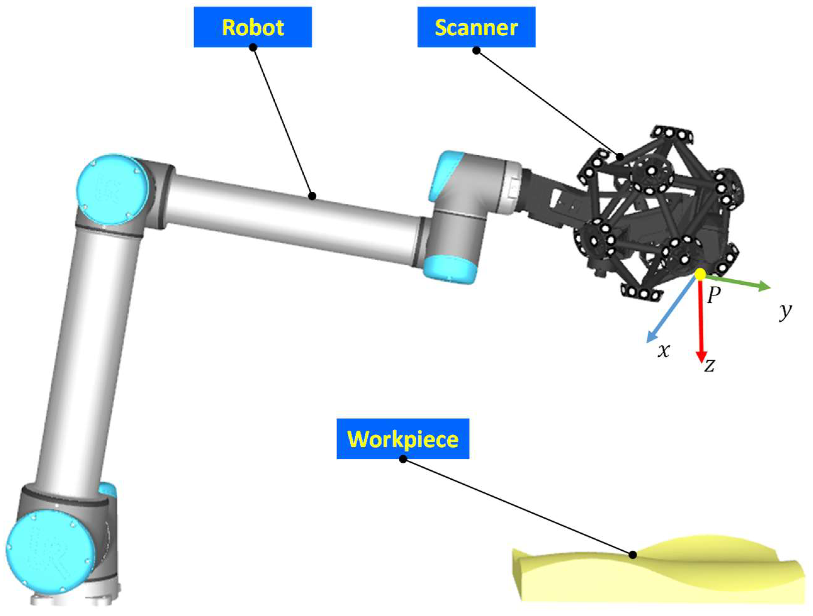
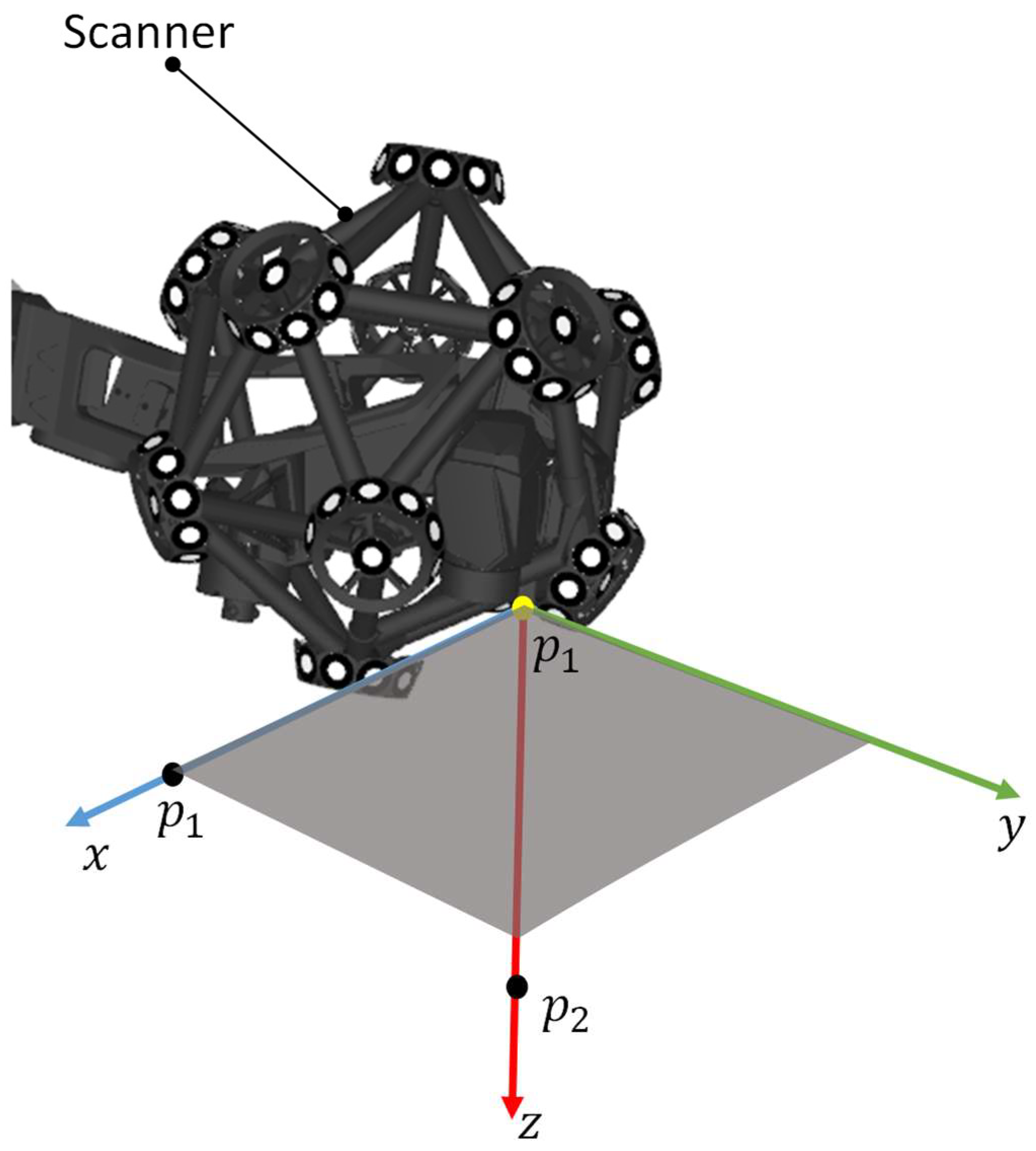
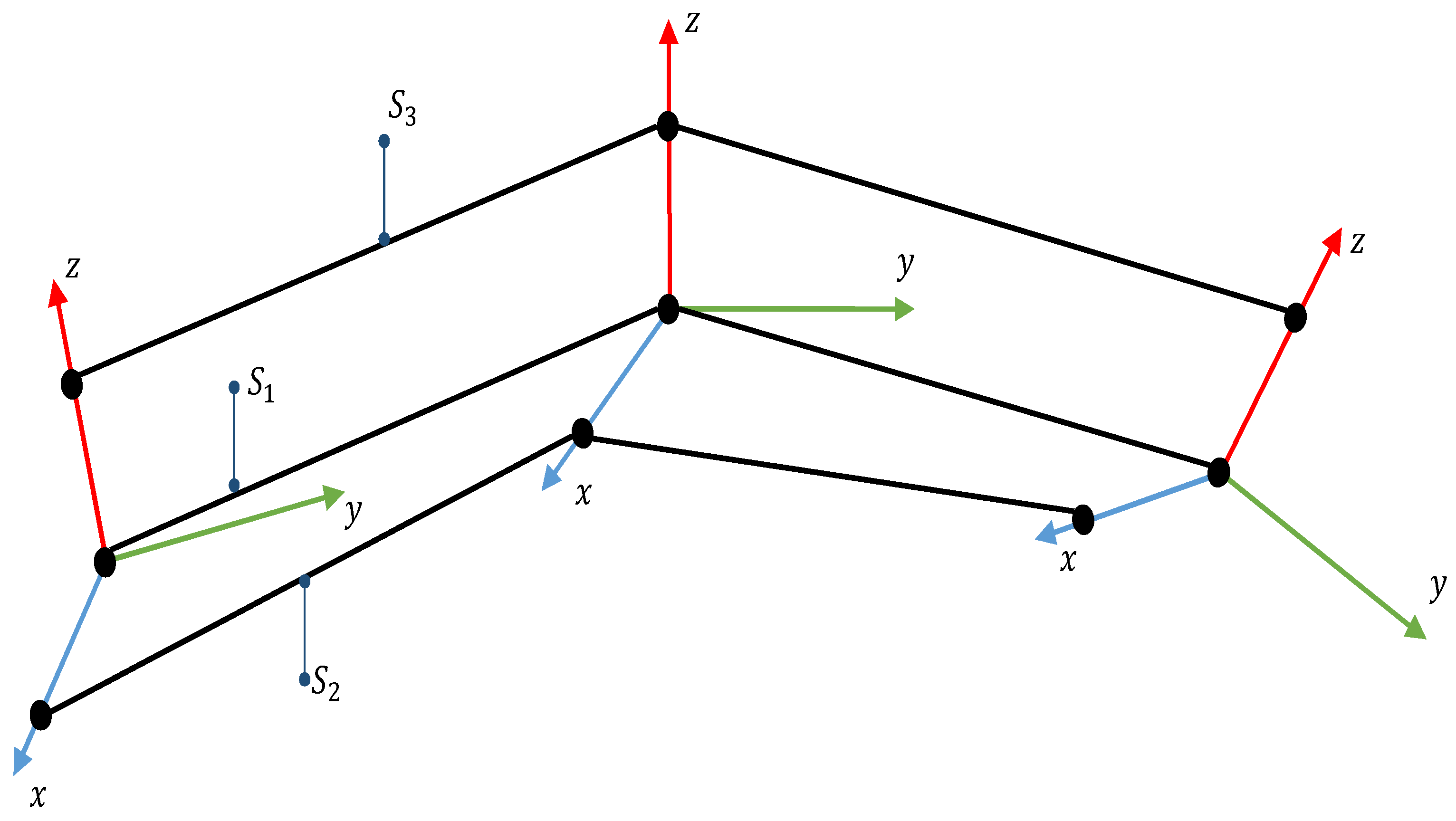
As illustrated in Figure 4, the position of the laser scanner within the workpiece coordinate system is defined by the vector . In three-dimensional space, there is no universal method for describing pose, as orientation is based on Lie group manifolds. Rotation matrices, Euler angles, and quaternions are among the commonly employed methods for representing spatial poses. Due to the convenience of matrix algebra, rotation matrices have become widely utilized in pose description. However, when industrial robots move along a continuous path, it is necessary to decouple direction. To achieve this, a pose mapping method that correlates a rotation matrix with three points on a triple curve is adopted, as depicted in Figure 5, which facilitates the synchronous representation of position and pose in space.
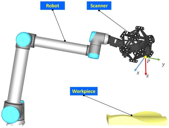
Figure 4.
Composition of robot scanning measurement system.
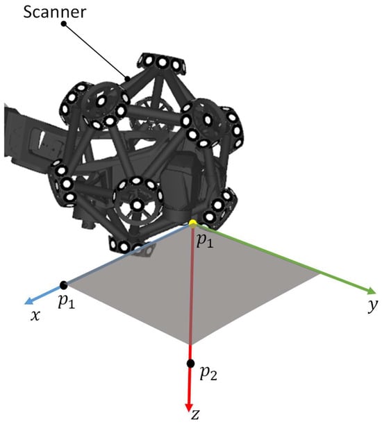
Figure 5.
Representing spatial pose based on coordinate system.
The robot actuates the laser scanner to navigate to a specific pose in space, with its position anchored by the first point . The point on the z-axis coordinate axis is designated as the second point , and the point on the x-axis coordinate axis is designated as the third point . Thus, the segment from the first point to the second point is designated as the z-axis, while the segment from the first point to the third point is designated as the x-axis. The y-axis is determined following the right-hand rule of the coordinate system; thereby, the local coordinate system of the scanner is established. As the laser scanner is guided by the robot along the planned path, the aforementioned three points will trace out three paths in space. The position and orientation of the laser scanner are defined based on the coordinates of the points of three paths at any given instant collectively.
As depicted in Figure 6, the first path represents the positional path of the laser scanner, while the second path and the third path are combined to ascertain the orientation of the laser scanner. To achieve a smooth path position, the corners of path is smoothed. Given that the measurement accuracy of laser scanners is contingent upon the tilt of their z-axis, it is imperative to stringently control the errors in the z-axis direction of the laser scanner. To achieve a smooth path posture, the corners of path is smoothed.
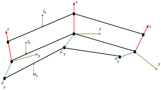
Figure 6.
Position and attitude path of laser scanner.
3.2. Smooth Position of Scanning Measurement Path
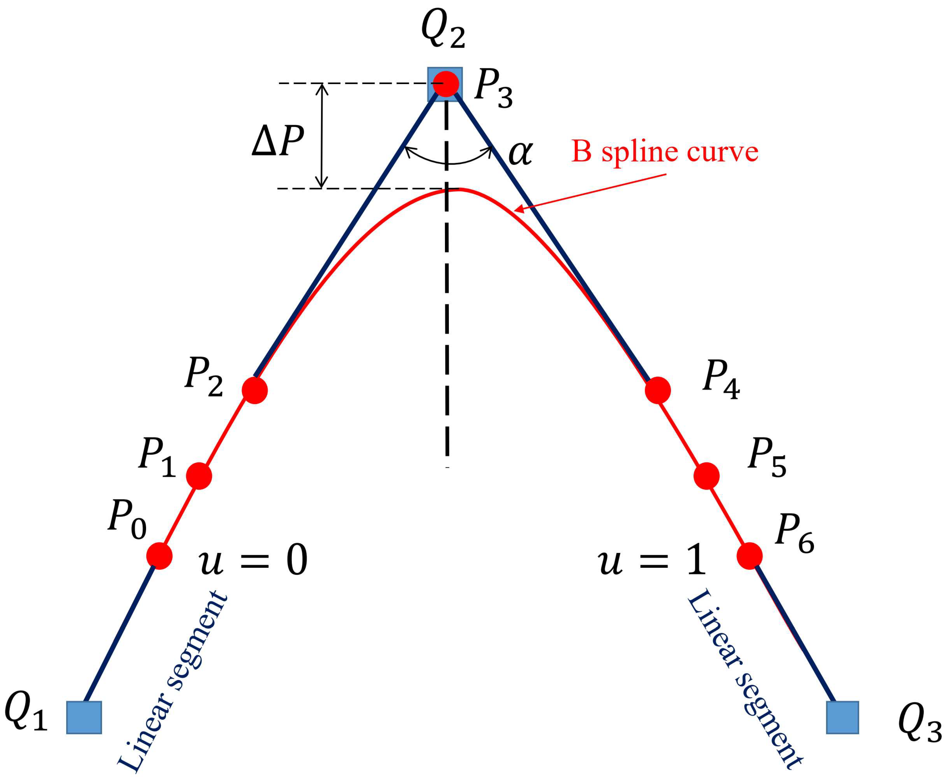
The scanning measurement path generated by the robotic scanning measurement path generation method is proposed in Section 2 of this paper. Taking three adjacent positional path points in the scanning measurement path as an example, this paper illustrates the principle of position smoothing. Figure 7 shows the composition of smooth curves for position corners. The B-spline curve in Figure 7 is the smooth curve of the position corner, and the linear segment is the transition line of the smooth curve of the adjacent position corner. The corner is the tip composed of two adjacent linear laser scanner path segments and . The position and direction vectors of are represented as , , where , , , . The B-spline curves (as shown by the red curve in Figure 7) are interposed between neighboring linear segments of the path (as shown by the blue path formed by Q1Q2 and Q2Q3 in Figure 7) to smooth position corners. The B-spline curve’s optimal control points are determined with respect to the predefined position error threshold and the requirements for smooth acceleration and jerk at the transitions where the B-spline curve meets the linear laser scanner path segments.
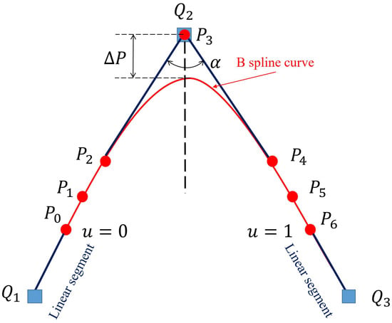
Figure 7.
Composition of smooth curves for position corners. The B-spline curve in the figure is the smooth curve of the position corner, and the linear segment is the transition line of the smooth curve of the adjacent position corner.
The B-spline curve interposed between the path segments of a linear laser scanner is characterized by basis functions, control points, and degrees, with the formula presented as follows:
where is the parameter of the B-spline curve, is the position of the laser scanner, is the control point of the B-spline curve, is the basis function, and is the degree of the B-spline curve.
The basis function is a function of the geometric parameter and the knot vector , as defined by Equation (3):
where the limit condition :
To maintain the integrity of the B-spline curve, achieving third-order continuity at the junction with the linear segment is essential. To achieve third-order continuity at the mentioned junctions, the B-spline curve is configured with a degree of 5 and is assigned 7 control points. The B-spline curve’s third-order continuity at these points is achieved by setting its degree to 5 and its number of control points to 7.
The non-periodic knot vector is formulated as U = [0, 0, 0, 0, 0, 0.5, 1, 1, 1, 1, 1, 1] to maintain the symmetry of the position-smooth B-spline curve. The basis function of a B-spline curve with smooth corner points at the 5th order can be computed utilizing Equations (3) and (4). By the values of the basis functions being substituted into the equation, we can derive the B-spline curve equation with smooth position and corner points. Further calculation of the position of the control point is necessary to fully define the B-spline curve with a smooth position.
The strategic selection of non-periodic knot vectors ensures that the B-spline curve interpolates through the first control point and the last control point , and is tangent to the segments and , as depicted in Figure 7. To preserve the position and tangential continuity at the juncture between the linear segment and the B-spline curve, which is designed to have a smooth position, the initial trio of control points , , and must be situated along the laser scanner’s path segment . In a parallel fashion, the final trio of control points , , and should be positioned along the laser scanner’s path segment . The fourth control point is deliberately placed at the corner position to ensure the symmetry of the B-spline curve, thereby maintaining a smooth and continuous trajectory.
To maintain continuity in acceleration and jerk at the connection points and , it is imperative to maintain continuity of the laser scanner path at these junctions.
The second and third derivatives of the linear laser scanner’s path, relative to the path length s, are always zero. Correspondingly, at the connection points, the second and third derivatives of the position-smooth B-spline curve with respect to the laser scanner path length s also equal to zero, which can be expressed as:
The second and third derivatives of the B-spline curve is calculated at the connection point iteratively five times. And by equating them with the corresponding value of the linear laser scanner path, we can obtain
The sufficiency of the aforementioned equation is contingent upon the validity of the following equation:
Assuming that , the derivative of the parameter u of the B-spline curve with respect to the path length s can be calculated as follows:
where,
From Equations (10)–(12), it can be seen that when the values of and are equal to 0, the values of and tend towards 0:
This means that if Equation (13) is satisfied, continuity of can be achieved at the connection.
The second derivative of the B-spline curve at is:
Substituting k = 5 and n = 6, we obtain:
The second derivative of the B-spline curve at is:
Substituting k = 5 and n = 6, m =12, we obtain:
The third derivative of the B-spline curve at is:
Substituting k = 5 and n = 6, we obtain:
The third derivative of the B-spline curve at is:
Substituting k = 5 and n = 6, m =12, we obtain:
Combining Equations (13)–(21), the following expression is obtained [16,17]:
By solving Equation (22),
By solving Equation (23),
To achieve symmetry of the B-spline curve, the lengths of line segments and are kept equal and their length values are set to . From Equations (24) and (25), the lengths of line segments , , and are , , and respectively. The value of the length is calculated by setting the position error constraint .
From Figure 7, it can be seen that the maximum position error represented by the B-spline curve defined by the equation occurs at the midpoint of the spline curve. The maximum position error is:
To ensure that the paths before and after smoothing can achieve complete coverage of the workpiece without compromising measurement integrity, the maximum position error ∆P must not exceed the user-set position error limit :
This results from each linear segment of the laser scanner’s path being utilized to smooth the corners at its own start and end points. Therefore, the maximum allowable lengths of the straight line segments and are one third of the lengths of the toolpath segments and , respectively, which can be expressed as,
Since the lengths of and are , we can use the above equation to obtain:
Combining Equations (27) and (29), the constraint of the final l-p can be obtained as follows:
where is the error constraint on the position of the laser scanner and is the angle between the neighboring line segments and .
3.3. Smooth Posture of Scanning Measurement Path
The commonly used position and attitude smoothing method currently separates position and attitude information. For position, the position information is stored as spatial coordinates and then smoothed; for attitude, the attitude parameters are represented by Euler angles. However, this does not directly control axial errors and requires the use of Jacobian matrices to convert Euler angles into axial errors. The above method cannot directly control axial error.
Therefore, based on Section 3.1 of this article, a pose information representation method is proposed based on multiple curves, which stores position and pose information as line segments in space. In terms of position information storage, the position information of the laser scanner is stored as the origin of the coordinate system. And in terms of direction information storage, the direction information of the laser scanner is stored as the coordinate axis of the coordinate system.
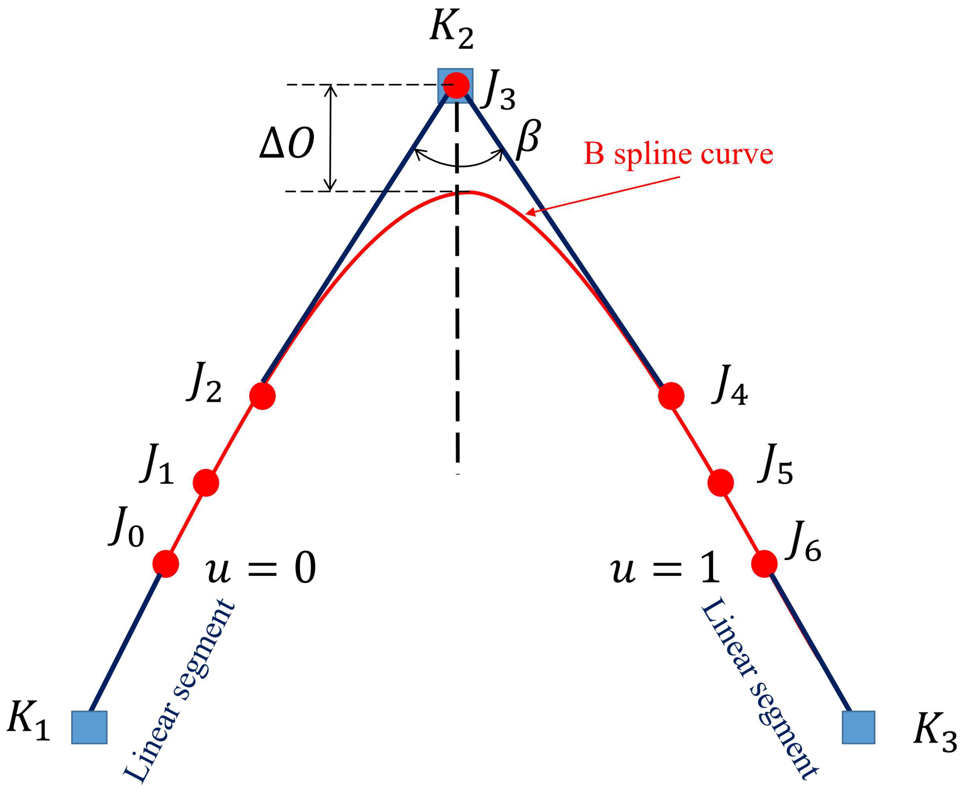
To ensure the continuity of the scanner’s velocity, acceleration, and deceleration as it passes through the corners of the scan direction, the B-spline curve (as shown by the red curve in Figure 8) is used to smooth the local corners of the laser scanner’s z-axis path (as shown by the blue path formed by Q1Q2 and Q2Q3 in Figure 8). The inserted B-spline curve is defined by basis functions, control points, and degrees, and its formula is as follows:
where is the parameter of the B-spline curve, is the position of the laser scanner, is the control point of the B-spline curve, is the basis function, and is the degree of the B-spline curve.
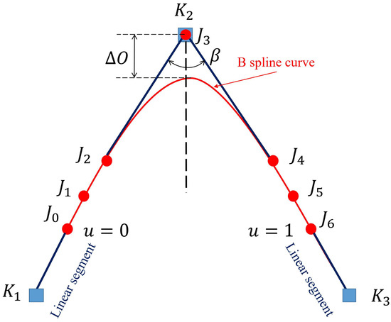
Figure 8.
Composition of smooth curves for attitude corners. The B-spline curve in the figure represents the smooth curve of the attitude angle points, linear segment is the transition line between smooth curves of adjacent attitude angles.
To maintain continuity in the scanner’s velocity, acceleration, and jerk at its directional corners, acceleration and jerk when passing through the scanner’s directional corners, the degree and number of control points of the scanner’s directional corner smoothing curve are set to 5 and 7, respectively. For geometric symmetry of the B-spline curve, the periodic node vector of the scanner direction corner smoothing curve is constructed as follows: U = [0, 0, 0, 0, 0, 0, 0.5, 1, 1, 1, 1, 1, 1].
To ensure the continuity of velocity, acceleration, and deceleration of the laser scanner as it passes through the directional corner of the laser scanner, it is necessary to ensure the continuity of the laser scanner path at the connection point. For a linear laser scanner path, the directional smooth B-spline curve always has zero 2nd and 3rd derivatives relative to the parameter u at = 0 and = 1. By referring to the derivation of Equations (14)–(21) in this paper, the expression can be obtained as:
By solving Equation (32),
By solving Equation (33),
To maintain symmetry of the B-spline curves, the lengths of line segments and are kept equal. From Equations (34) and (35), the lengths of line segments , , and are , , and , respectively. The value of length is calculated by setting the directional error constraint .
From Figure 8, it is observable that the peak directional error ∆O, as given by the B-spline curve’s equation, happens at the spline’s midpoint. The maximum position error is:
where , .
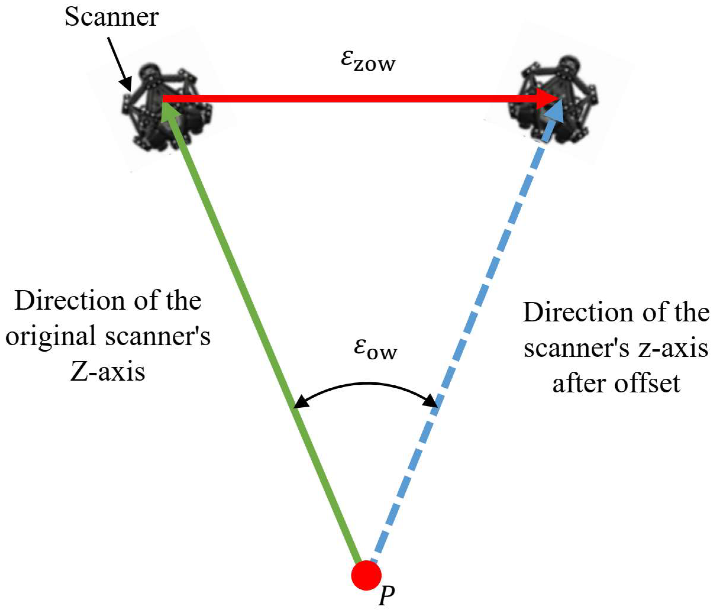
In the world coordinate system, the scanner directional error caused by local corner smoothing is known, as depicted in Figure 9. The maximum directional error of the scanner , can be solved by geometric relations. The corresponding maximum directional position error in the z-axis direction is:
where is the offset distance along the zaxis where the scanner is located.
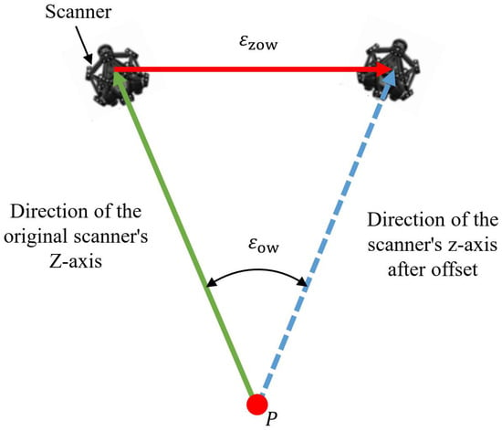
Figure 9.
Directional error of scanner.
To ensure that the paths before and after smoothing can achieve complete coverage of the workpiece without compromising measurement integrity, by combining Equations (36) and (37), it can be concluded that the condition for satisfying the maximum directional error is:
Each scanner direction segment has a corner at the beginning and end. To ensure synchronization of scanner position and direction, the linear scanner path for creating directional B-spline curves should not exceed one-third of the line’s total length:
Considering that = , combined with Equation (38), the final constraint condition for is:
By introducing position tolerance and orientation tolerance (Equations (30) and (40)), the robot scanning measurement path smoothing method proposed in this paper achieves submillimeter-level precision control, meeting the accuracy requirements of laser scanning measurement.
4. Synchronization of Position and Attitude for Robot Scanning Measurement
To ensure the acceleration continuity of each joint of the robot, the velocity of the scanner posture should be synchronized with the displacement velocity of the scanner position. Based on the smoothing algorithm for position and direction corners in Section 3, the transition parts of adjacent position corners and adjacent direction corners of the scanning path are replaced with B-spline curves. By sharing the curve parameters, the synchronization of the position and orientation of the scanning measurement path is achieved.
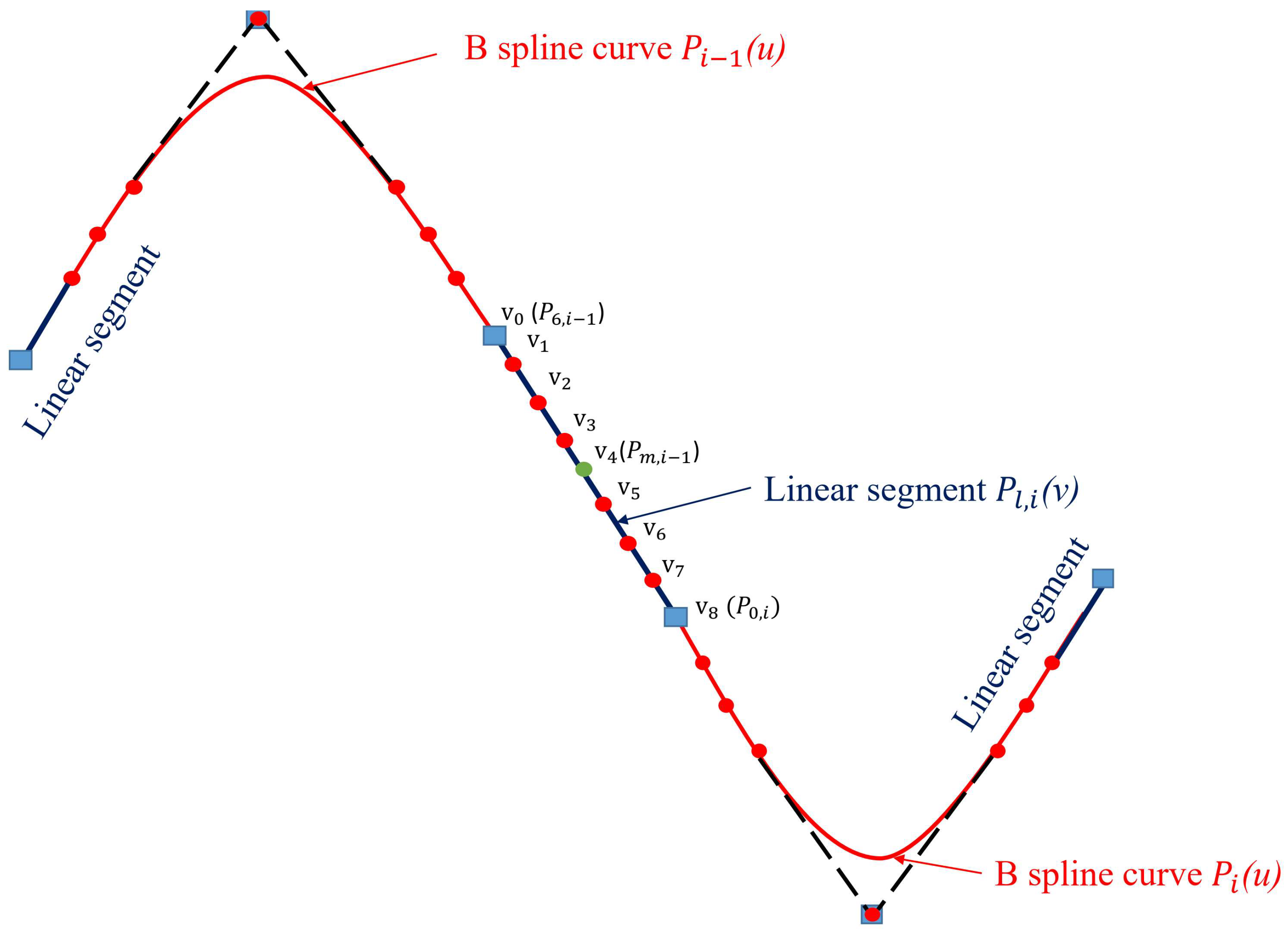
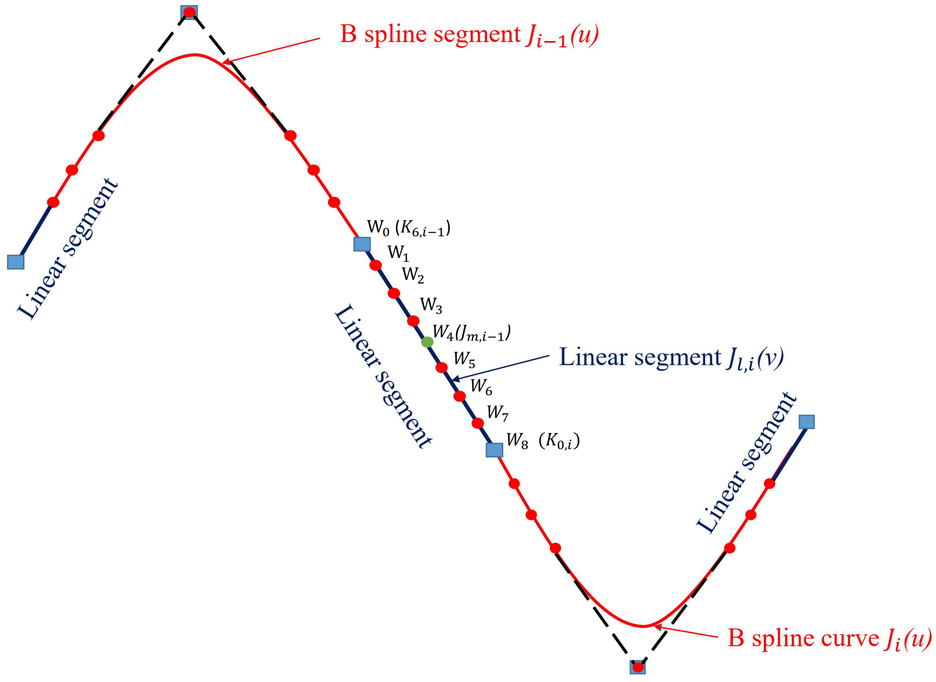
As shown in Figure 10, and are the smooth curves of the (i − 1)th and i-th position corner points, respectively, and is the transition curve between the two position corner points. As shown in Figure 11, and are the smooth curves of the (i − 1)th and i-th directional vertices, respectively, and is the transition curve between the two directional vertices. The B-spline curve’s degree remains 5, as specified in the Section 3. To adjust the synchronization between the position and orientation of the scanner, the number of control points is selected as 9. The B-spline curve’s smoothing node vectors for the scanning path’s position and orientation corner points are identical: U = [0, 0, 0, 0, 0, 0, 0.5, 0.5, 0.5, 1, 1, 1, 1, 1, 1].
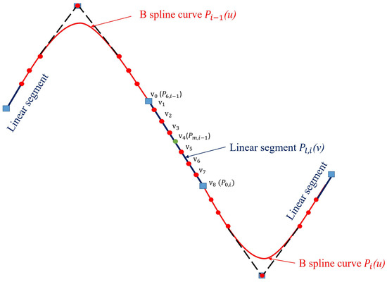
Figure 10.
Composition of scanner position corner transition curve.
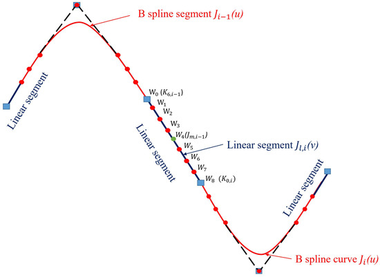
Figure 11.
Composition of scanner direction corner transition curve.
The B-spline curves of the linear part of the scanner’s position and direction are represented based on Equations (41) and (42), respectively:
By referring to Section 3.2 and Section 3.3 of this paper, it can be concluded that to maintain the second and third-order geometric continuity at the junction between the B-spline curve and the original linear segment, the following criteria must be satisfied:
The length of is set to and the length of is set to . The above length values are substituted into Equation (43) and it can be obtained that:
Similarly, by referring to Section 3.2 and Section 3.3 of this paper, to preserve the second and third-order geometric continuity at the transition from the B-spline curve to the initial linear segment, the subsequent requirements must be fulfilled:
The length of is set to and the length of is set to . The above length values are substituted into Equation (45) and it can be obtained that:
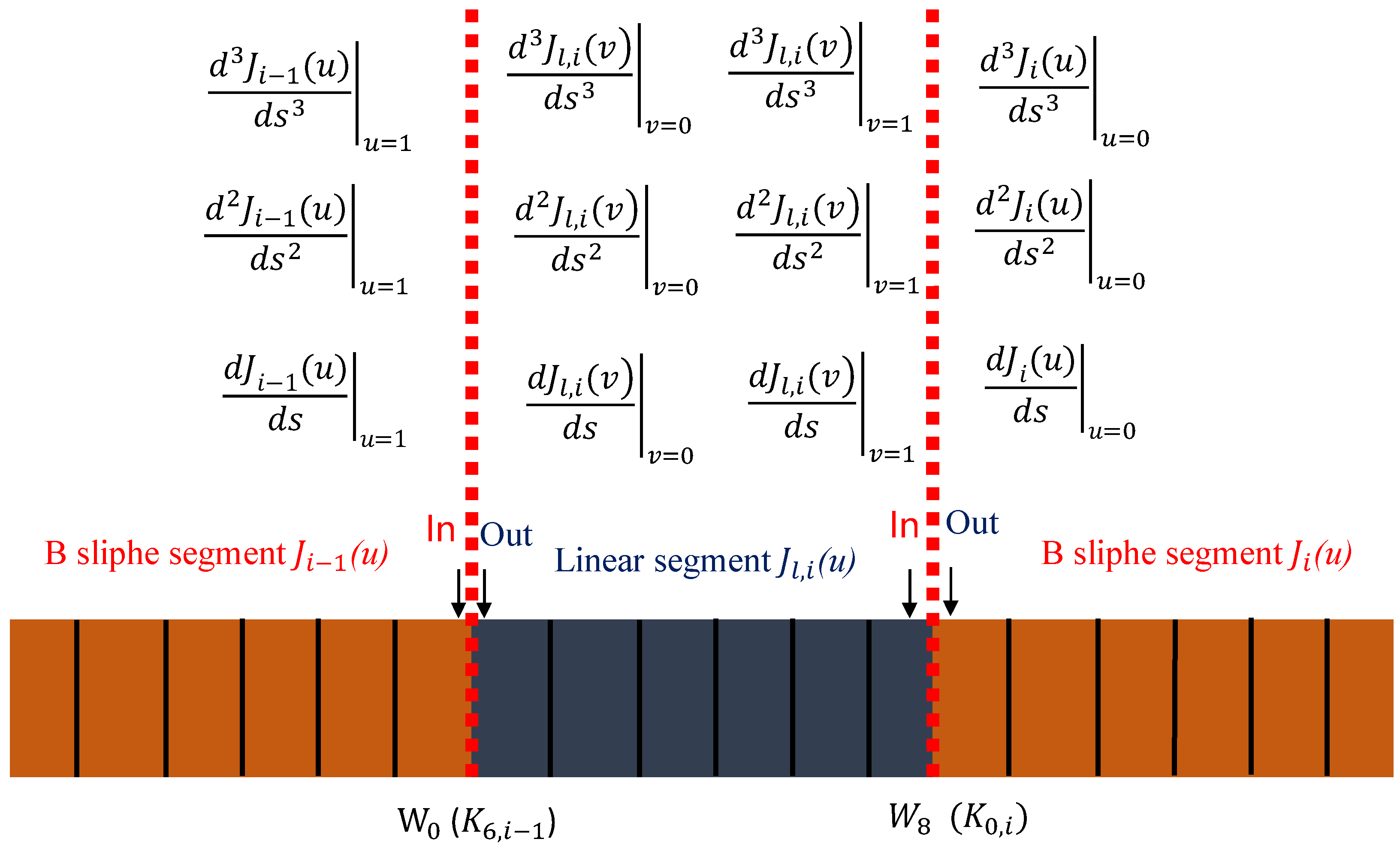
At the connection point in Figure 12, the first derivative, second derivative, and third derivative of the scanner direction relative to the scanner position are:
where .
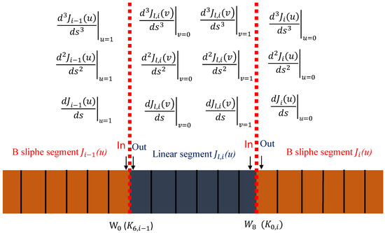
Figure 12.
Geometric continuity of corner transition curves.
At the connection point in Figure 12, on the direction corner transition curve, the first, second, and third derivatives of the scanner direction are relative to the scanner displacement:
The sufficient condition for achieving continuous synchronization of the scanner direction at the junction point with respect to the scanner position by combining Equations (47) and (48) is:
Combining Equation (49), in order to achieve continuous synchronization of the direction of the scanner at the junction point with respect to the scanner position, the lengths of and are:
where , and .
According to Equation (49), the sufficient condition for achieving continuous synchronization of the direction of the scanner at the connection point relative to the position of the scanner is:
Combining Equation (51), in order to achieve continuous synchronization of the direction of the scanner at connection point with respect to the scanner position, the lengths of and are:
where .
By combining Equations (50) and (52), the control points for the position smooth transition curve and the direction smooth transition curve can be obtained as follows:
where .
where .
5. Experiments and Discussions
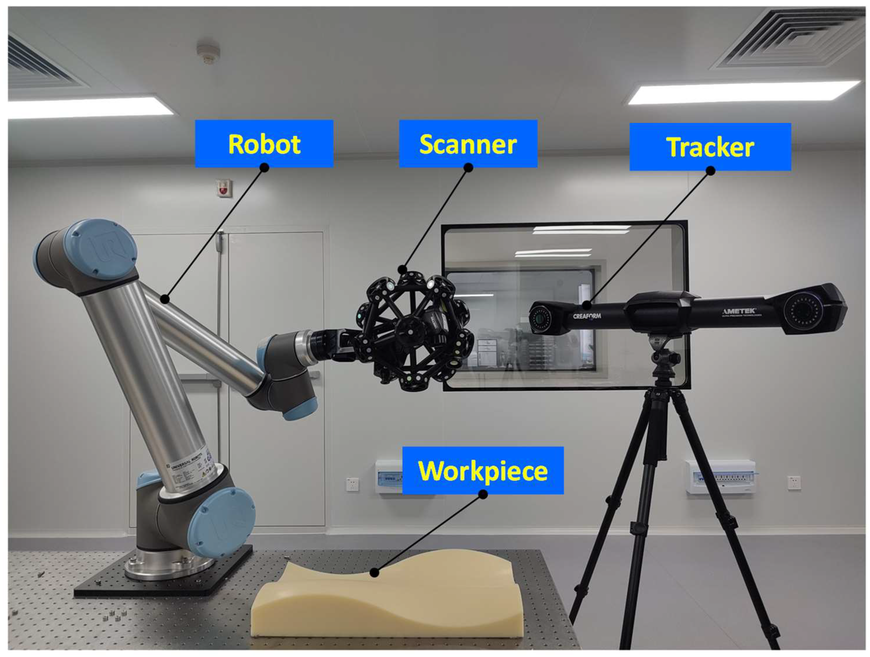
As illustrated in Figure 13, our experimental apparatus includes a UR 10 robot, its corresponding controller, a laser scanner, and the workpiece that requires measurement.
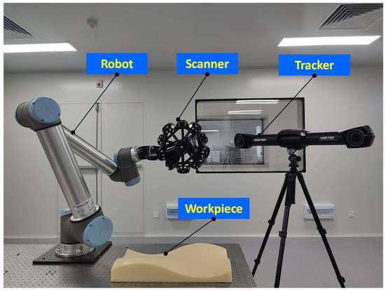
Figure 13.
Robot scanning measurement system diagram.
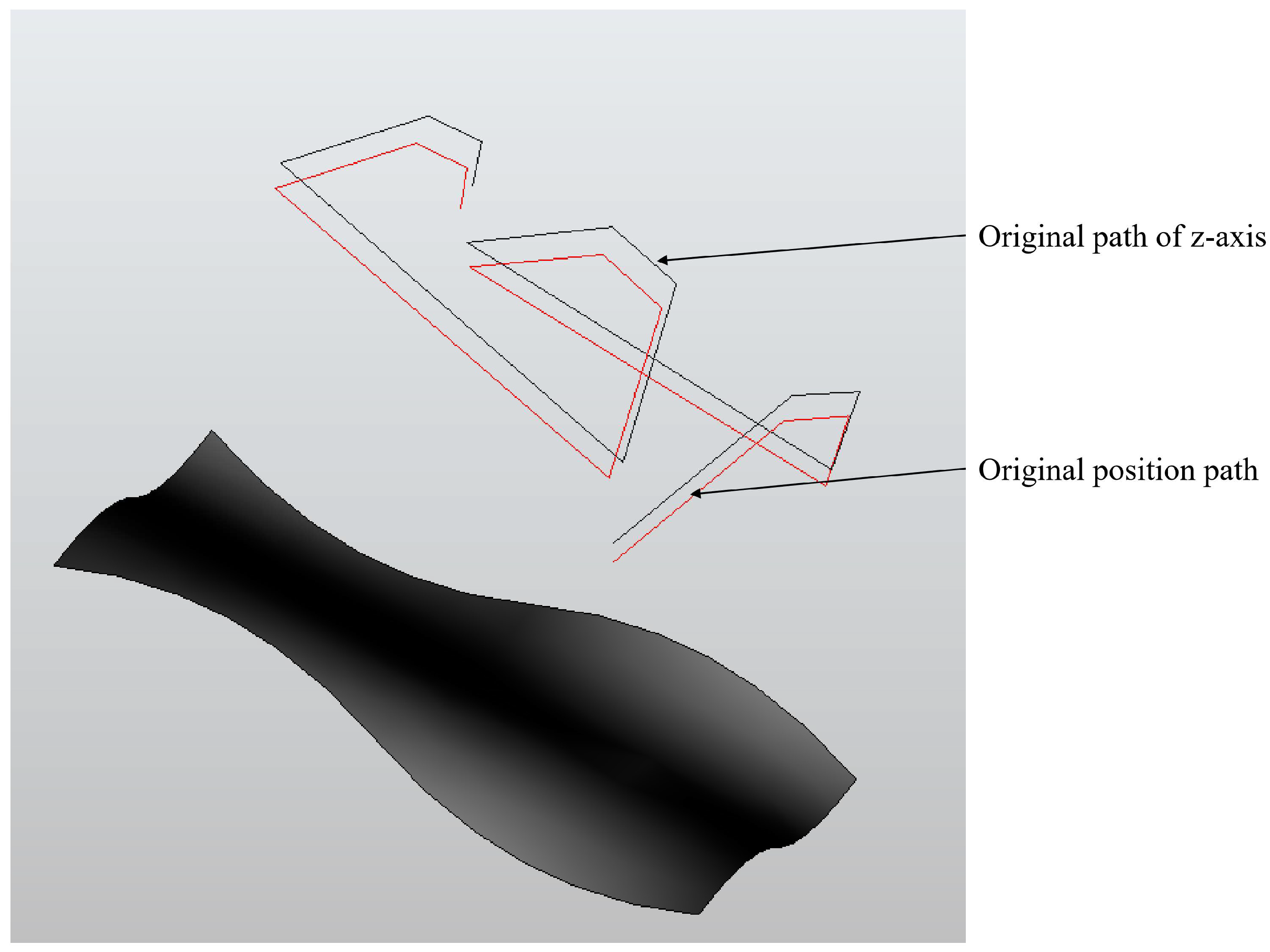
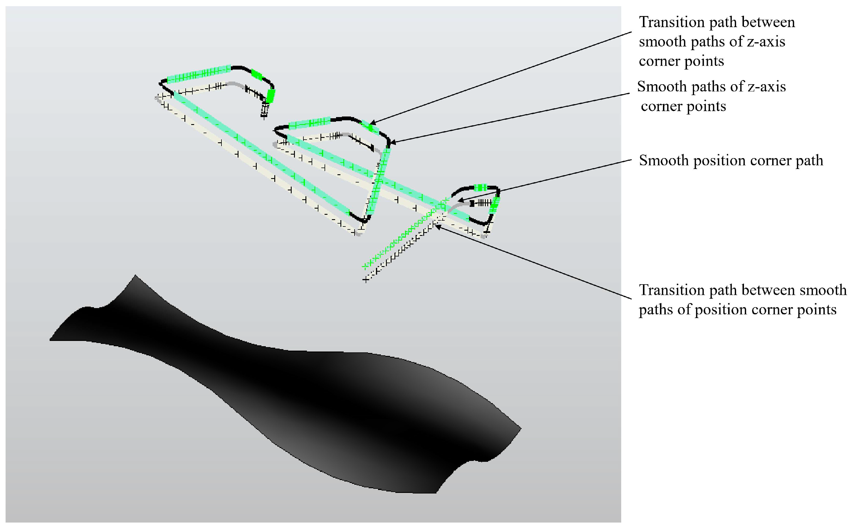
The scanning measurement path generated in Section 2 of this paper is shown in Figure 14. It can be observed that there are obvious acute, right, and obtuse angles at the corners. To smooth the corners, we apply the path smoothing algorithms proposed in Section 3 and Section 4 of this paper to smooth the position and orientation of the corners and obtain the smoothed scanning measurement path as shown in Figure 15.
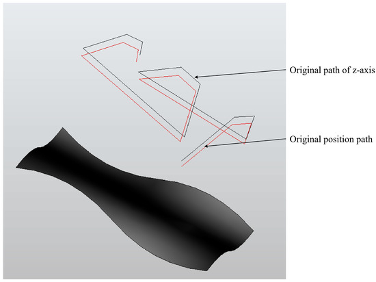
Figure 14.
Robot scanning measurement path.
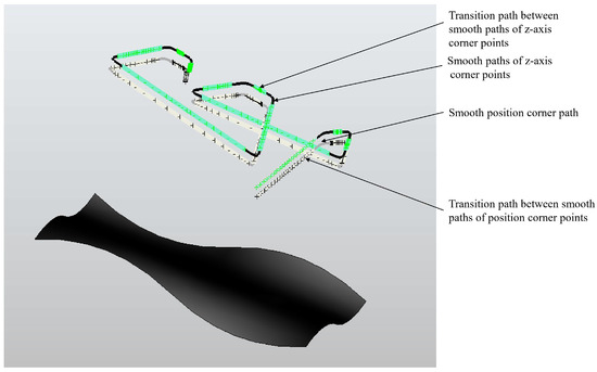
Figure 15.
Smooth scanning measurement path generated based on the multi-curve path smoothing algorithm proposed in this paper.
5.1. Robot Joint and TCP Tracking Error Experiment
Vibrations caused by a robot-mounted laser scanner when traversing path corners can impact the robot’s joint alignment inaccuracies and the end-effector’s tool center point (TCP) deviations. Among them, the robot joint tracking error is the difference between the expected joint position and the actual joint position. The TCP tracking error is the difference between the expected TCP position and the actual TCP position.
To assess the efficacy of the proposed path smoothing algorithm in reducing tracking discrepancies for both robot joints and the TCP. We built an appropriate robot motion monitoring platform to track the robot’s dynamic movement condition throughout its path traversal. The robot is controlled to travel the scanning measurement smooth path generated by our proposed multi-curve-based scanning path smoothing algorithm and the scanning measurement smooth path generated by the path smoothing algorithm proposed in the reference literature [3]. And the joint tracking error and TCP tracking error are monitored during the motion process.
The detailed process for obtaining joint tracking errors and TCP tracking errors is as follows:
- (1)
- The robot’s joint space error is defined as the absolute difference between the commanded joint angles and the real-time joint angles of the robot. Its mathematical expression is as follows:
- (2)
- The robot TCP position error is defined as the absolute difference between the commanded TCP position and the real-time TCP position of the robot. Its mathematical expression is as follows:
- (3)
- The robot TCP orientation error is defined as the absolute difference between the commanded TCP orientation and the real-time TCP orientation of the robot. Its mathematical expression is as follows:
5.1.1. Robot Joint Tracking Error Experiment
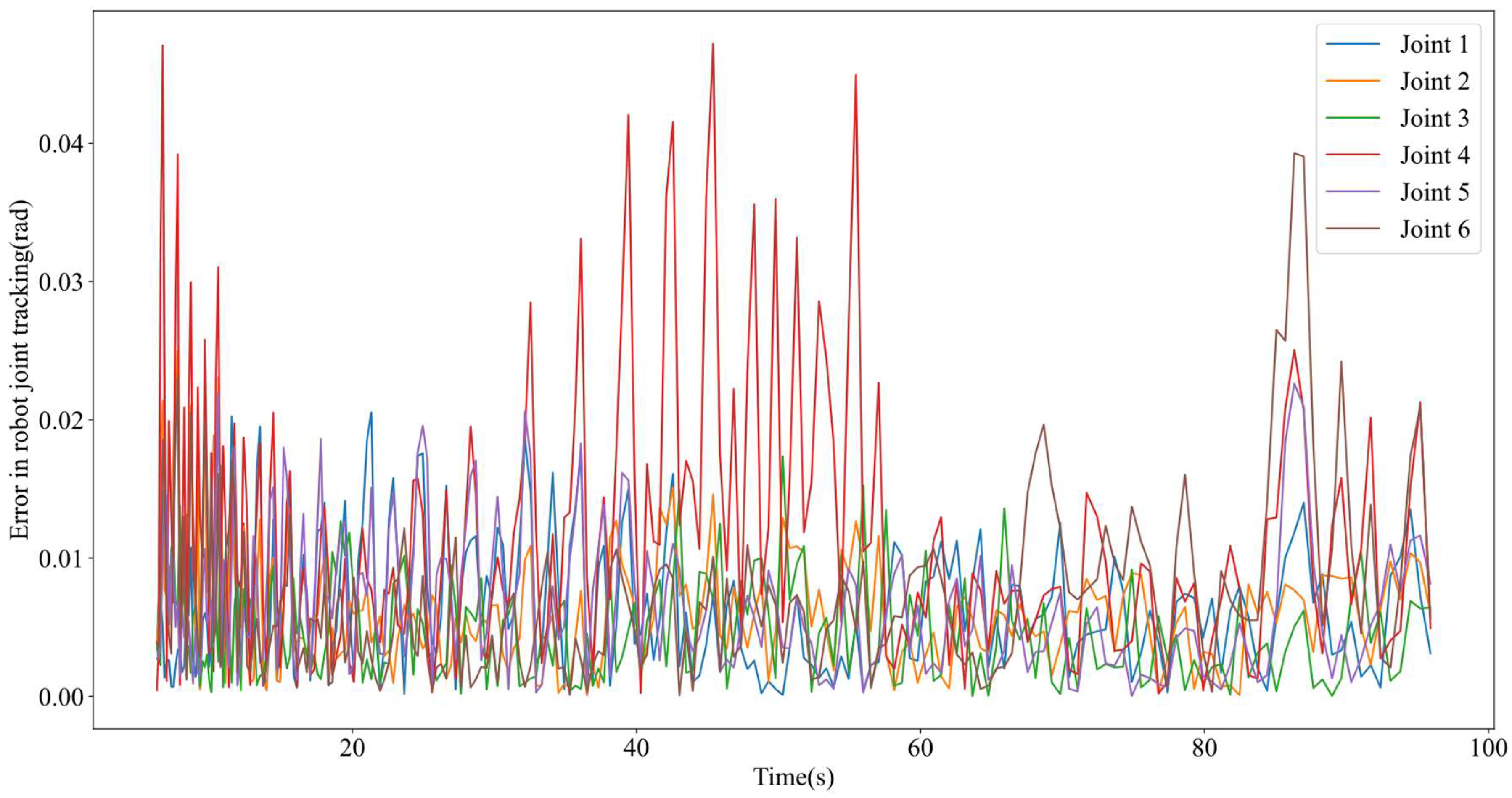
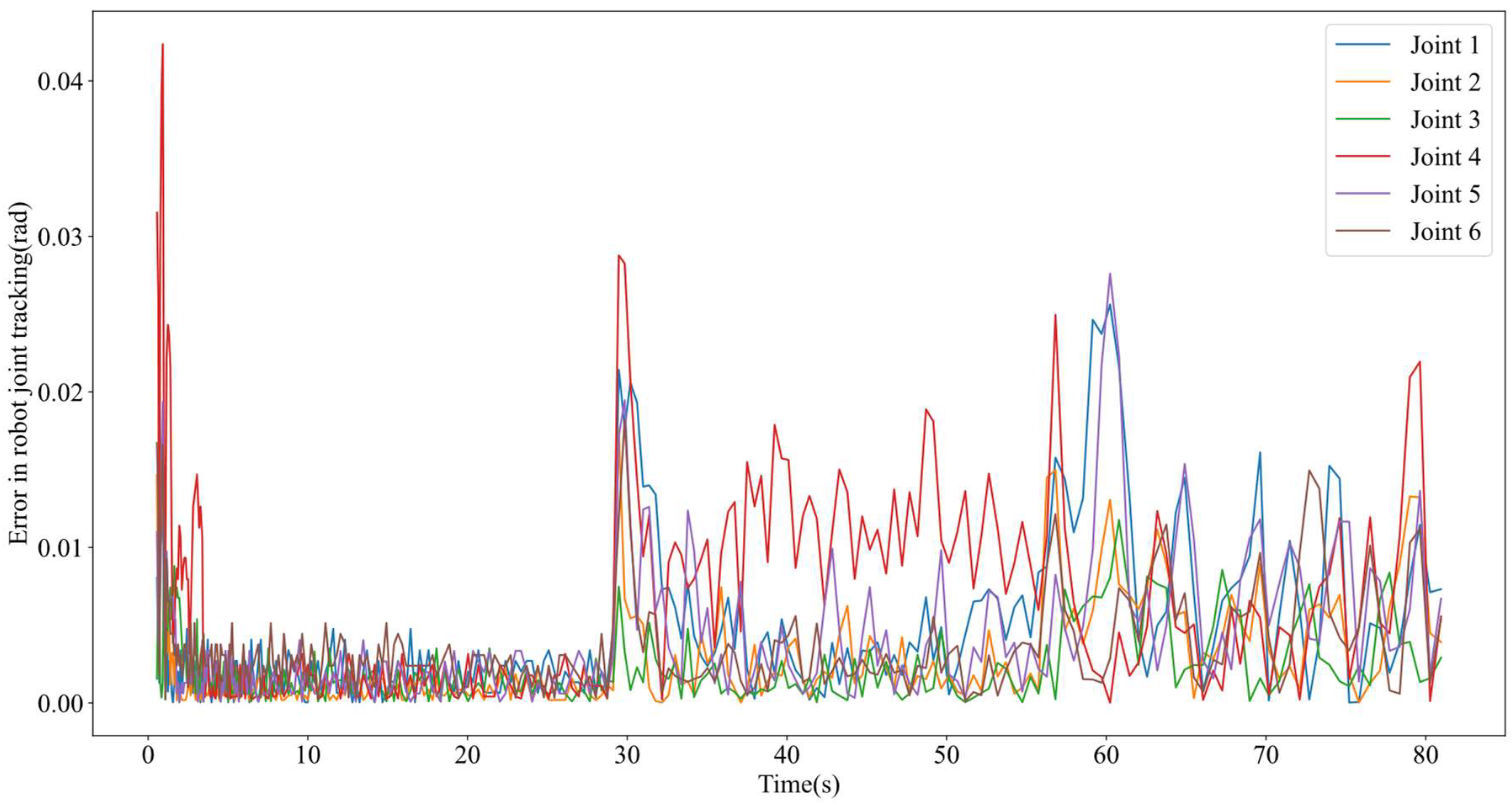
The fluctuations in the joint angle tracking error are depicted in Figure 16. The maximum joint tracking error for two different path smoothing methods is summarized in Table 1. The root mean square error of the joint tracking for two different path smoothing methods is summarized in Table 2. By analyzing Table 1 and Table 2, it can be concluded that:
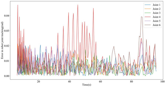
Figure 16.
Robot joint tracking error based on the scanning measurement path smoothing algorithm proposed in the reference literature [3].

Table 1.
Comparison of maximum joint tracking error between different path smoothing algorithms.

Table 2.
Comparison of root mean square error in joint tracking between different path smoothing algorithms.
- (1)
- Maximum error of robot joint tracking
From Table 1, it is observable that the smooth path generated by our proposed multi-curve-based scanning measurement path smoothing algorithm has a higher degree of improvement in the maximum tracking error of joints 2, 3, 4, and 6 of the robot compared to the scanning measurement smooth path generated by the path smoothing algorithm in the reference literature. Compared to the path smoothing algorithm mentioned in the reference [3], the proposed path smoothing algorithm reduces the maximum error of robot joint tracking by up to 53.69%. These findings further validate the potency of our proposed algorithm for path smoothing.
- (2)
- Root mean square error of robot joint tracking
Compared to the maximum error in robot joint tracking, the root mean square error in joint tracking can better reflect the tracking accuracy of robot joints. Therefore, we further calculate the root mean square error of the robot joint tracking and obtain the data shown in Table 2. As shown in Table 2, it is evident that the smooth path generated by our proposed multi-curve-based scanning measurement path smoothing algorithm has significantly improved the root mean square error of joint tracking for robot joints 1, 2, 3, 4, 5, and 6 compared to the path smoothing algorithm in the reference literature [3]. Compared with the path smoothing algorithm mentioned in the reference [3], the proposed path smoothing algorithm reduces the joint root mean square error by up to 80%. The above results further demonstrate the effectiveness of the proposed path smoothing algorithm.
5.1.2. Robot TCP Tracking Error Experiment
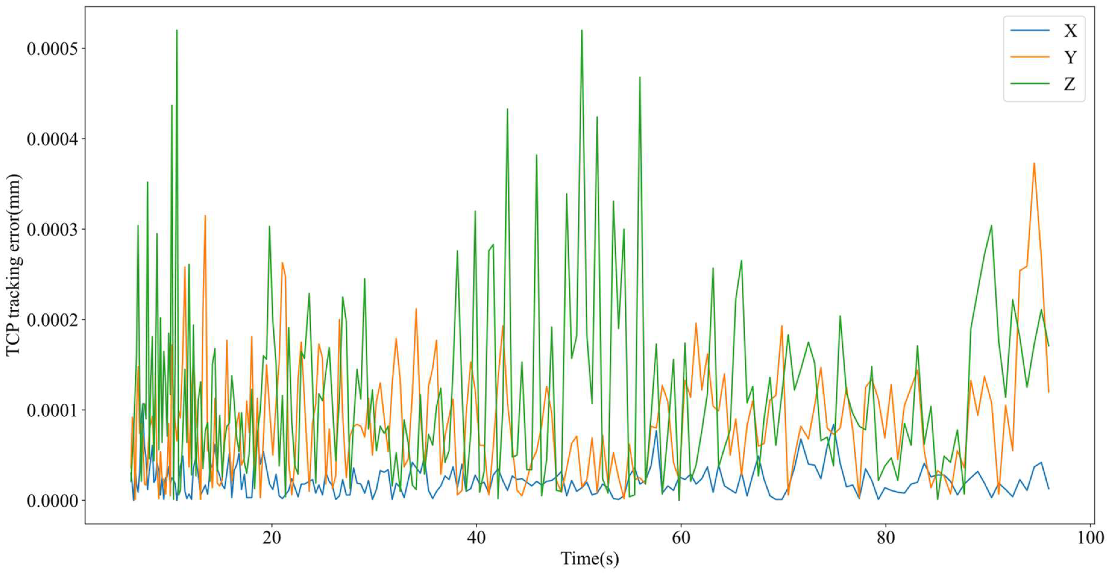
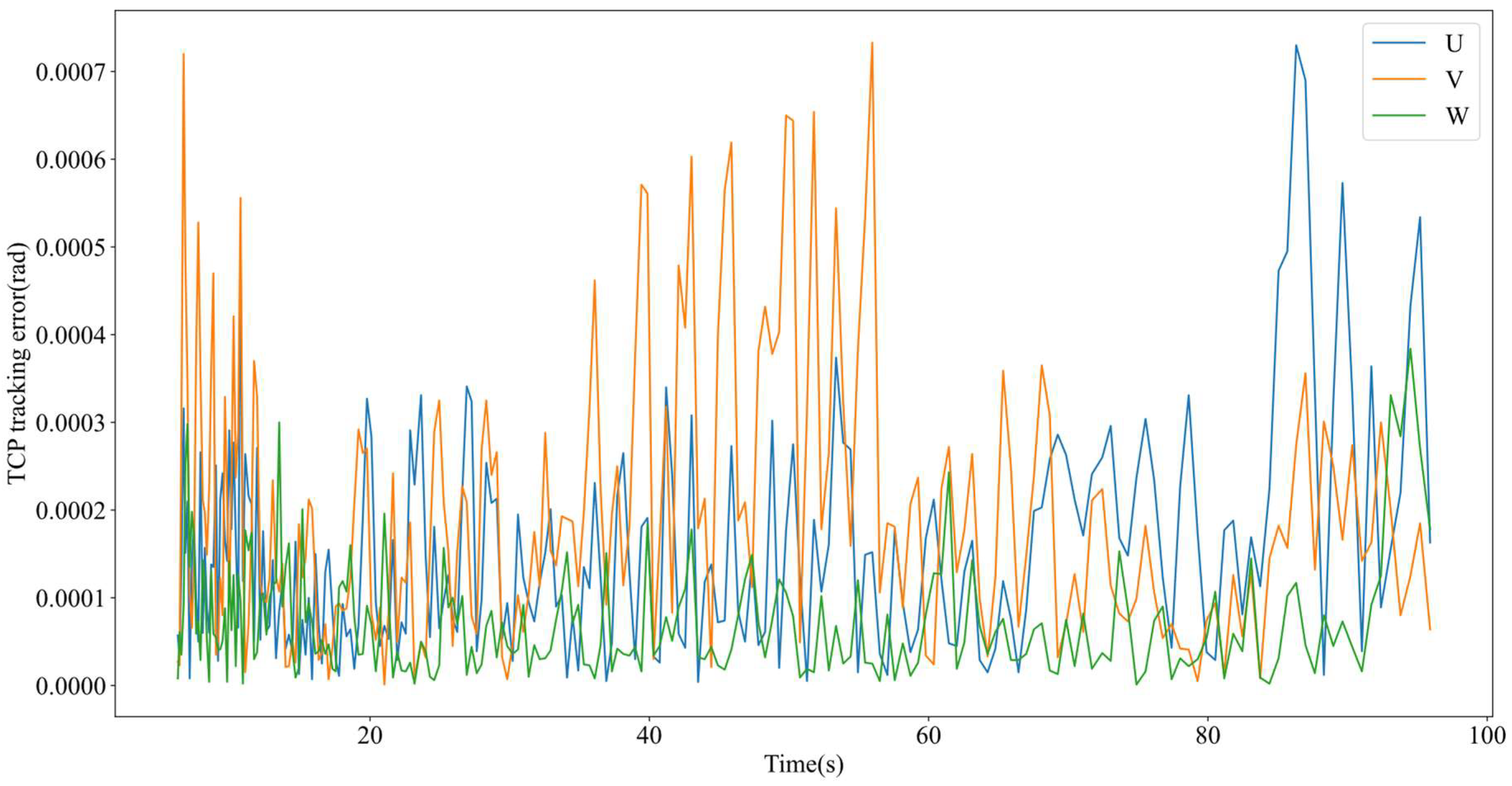
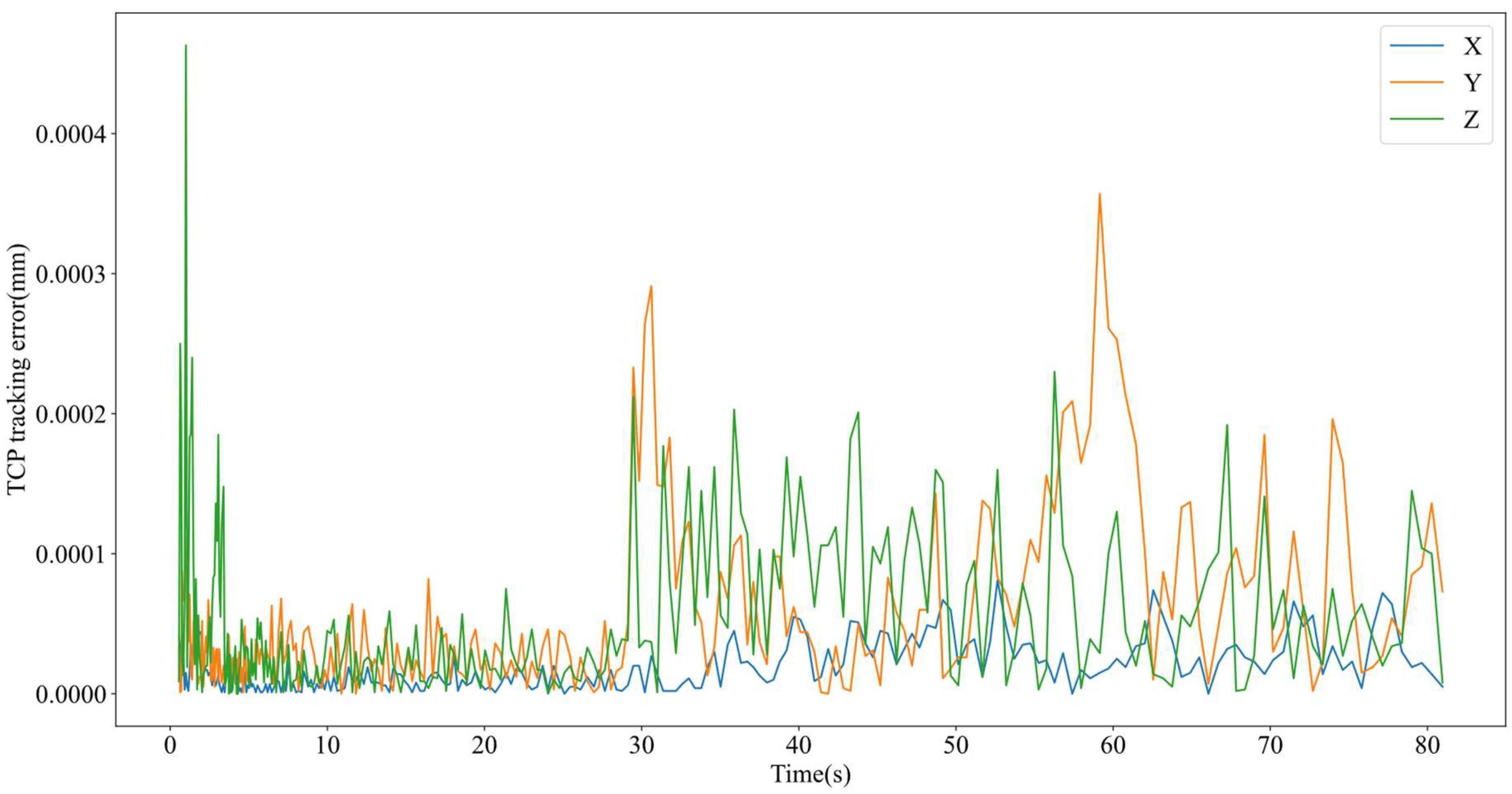
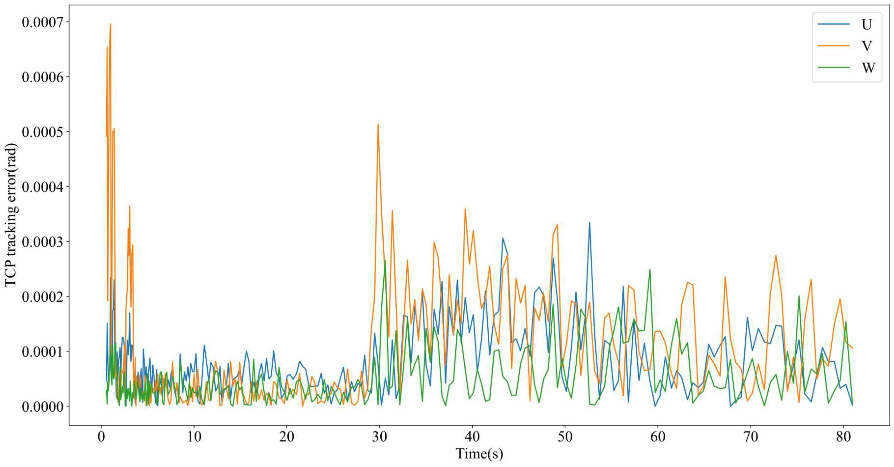
The variation of the TCP tracking error for robots is shown in Figure 17, Figure 18, Figure 19, Figure 20 and Figure 21. The maximum error of TCP tracking for two different path smoothing methods is summarized in Table 3. The root mean square error of TCP tracking for two different path smoothing methods is summarized in Table 4. By analyzing Table 3 and Table 4, it can be concluded that:
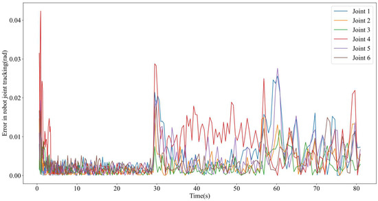
Figure 17.
Robot joint tracking error based on multi-curve scanning measurement path smoothing algorithm.
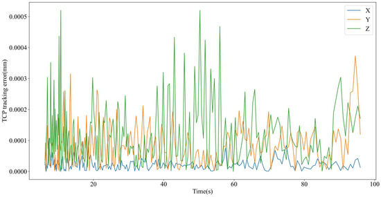
Figure 18.
TCP position tracking error based on the scanning measurement path smoothing algorithm proposed in the reference literature.
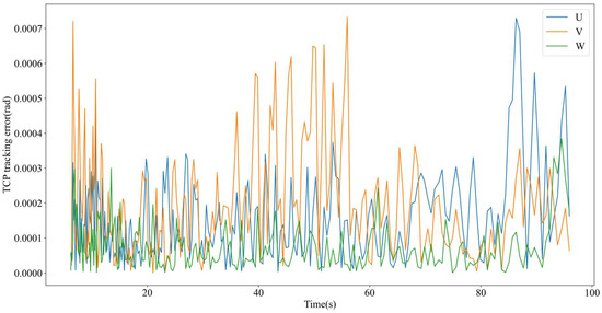
Figure 19.
TCP attitude tracking error based on the scanning measurement path smoothing algorithm proposed in the reference literature.
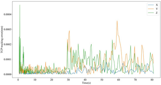
Figure 20.
TCP position tracking error based on multi-curve scanning measurement path smoothing algorithm.
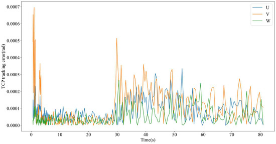
Figure 21.
TCP attitude tracking error based on multi-curve scanning measurement path smoothing algorithm.

Table 3.
Comparison of maximum TCP tracking error between different path smoothing algorithms.

Table 4.
Comparison of root mean square error in TCP tracking with different path smoothing algorithms.
- (1)
- Maximum error of robot TCP tracking
From Table 3, it can be seen that the smoothed path generated by our proposed multi-curve-based scanning measurement path smoothing algorithm has a higher degree of improvement in the maximum tracking error of the robot TCP position (X, Y, Z) and posture (U, V, W) compared to the smoothed path generated by the path smoothing algorithm in the reference literature [3]. Compared to the path smoothing algorithm mentioned in the reference [3], the proposed path smoothing algorithm reduces the maximum error of the robot TCP tracking by up to 66.67%. The above results further demonstrate the effectiveness of our proposed path smoothing algorithm.
- (2)
- Root mean square error of robot TCP tracking
Compared to the maximum error of robot TCP tracking, the root mean square error of TCP tracking can better reflect the tracking accuracy of robot TCP. Therefore, the root mean square error of robot TCP tracking is further calculated, and the data shown in Table 4 are obtained. From Table 4, it is apparent that the smooth path generated by our proposed multi-curve-based scanning measurement path smoothing algorithm has significantly improved the tracking root mean square errors in the position (X, Y, Z) and posture (U, V, W) of the robot TCP compared with the path smoothing algorithm in the reference literature [3]. Compared to the reference path smoothing algorithm, the proposed path smoothing algorithm reduces the joint root mean square error by up to 50%. The results presented above continue to show that the suggested path smoothing algorithm is effective.
5.2. Robot Scanning Measurement Experiment
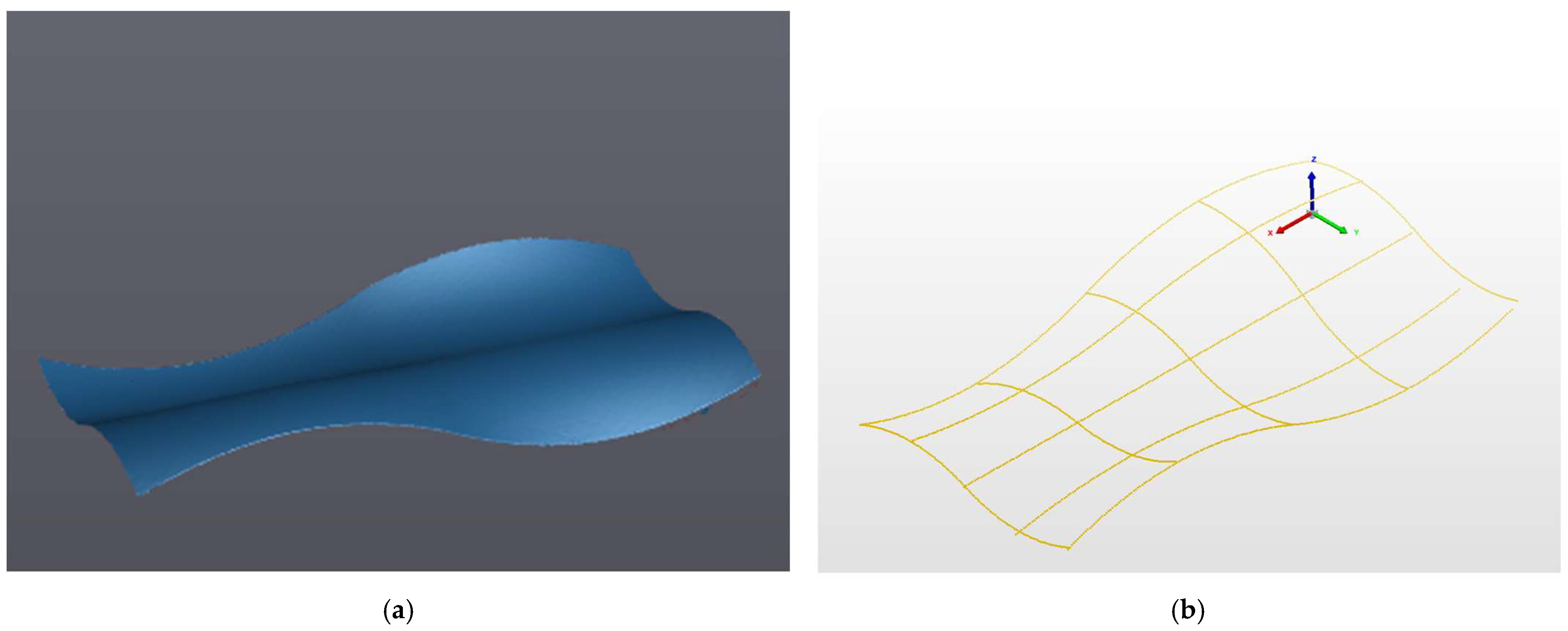
The performance of our proposed robot scanning measurement path smoothing algorithm based on multiple curves in terms of measurement accuracy is further validated. The robot is controlled to carry a laser scanner and measure the free-form surface workpiece along a scanning measurement smooth path generated based on the proposed path smoothing algorithm. The acquired measurement outcomes of the scanner are depicted in Figure 22a. For the high-precision measurement of the aforementioned free-form surface workpiece, an orthogonal coordinate measuring instrument is employed, with the results presented in Figure 22b.
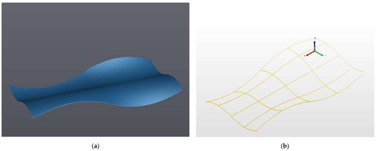
Figure 22.
Measurement results. (a) The figure shows the laser scanning measurement results, and (b) the coordinate measuring machine measurement results.
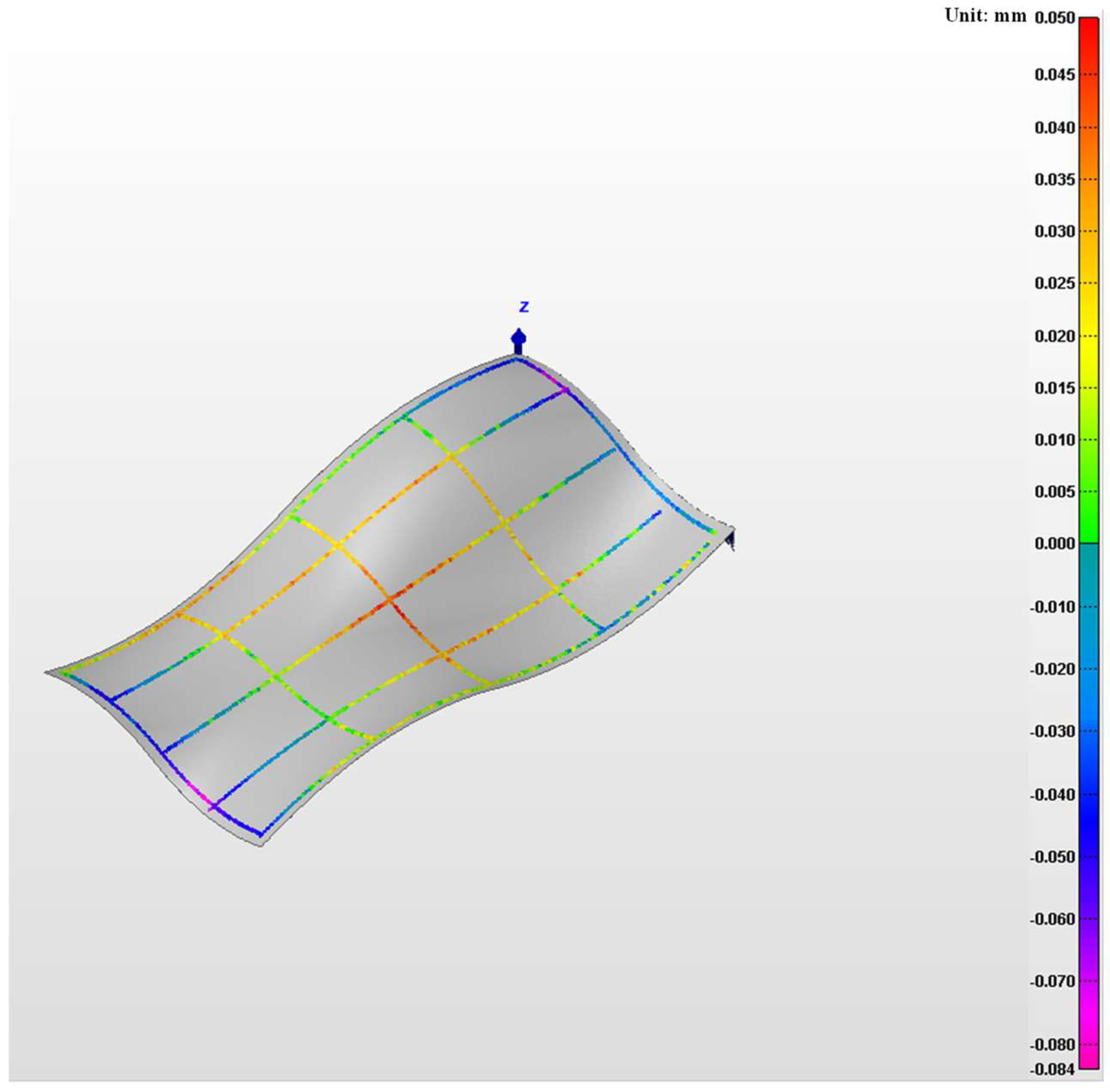
The discrepancies between the laser scanner’s measurements and those from the coordinate measuring machine are analyzed, with the error distribution displayed in Figure 23. The maximum recorded error is 0.084 mm, and the mean error is 0.003 mm; these values satisfy the precision specifications for laser scanners. These findings confirm the accuracy of our multi-curve-based robot scanning measurement path smoothing algorithm.
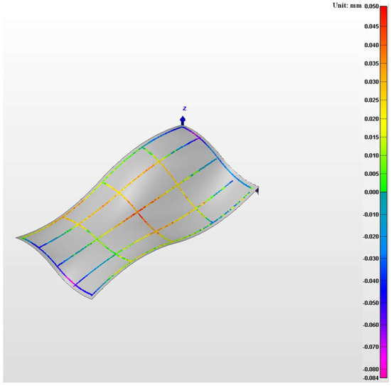
Figure 23.
Error comparison.
6. Conclusions
This paper proposes a robot scanning measurement path smoothing algorithm based on multiple curves to address the vibration problem of current robot scanning measurement paths. The position and posture of the laser scanner are stored as multiple curves, and the corners of the position curve and posture curve are smoothed based on a 5th-order B-spline curve. Based on the constraints of position error and direction error, as well as the geometric continuity constraint of the path, corresponding B-spline curves are generated. And based on the synchronization of position and posture and the geometric continuity of the path, adjacent position corner smooth curves and the connecting B-spline curves between adjacent position corner smooth curves are generated. Through experiments on robot tracking error and scanning measurement, it has been validated that the method suggested here is efficient in lowering robotic tracking discrepancies and maintaining measurement precision. Although this study employs scanning measurement as the case application, the proposed multi-curve synchronous parameterization framework can be extended to industrial scenarios such as welding and spray coating.
In future work, other types of curves can be further used for robot scanning and measurement path smoothing, and artificial intelligence-based path smoothing algorithms can be used to further improve the tracking and measurement accuracy of robots.
Author Contributions
Conceptualization, L.Y. and H.J. (Huakun Jia); methodology, L.Y.; software, C.C.; validation, C.C., Y.H. and X.W.; formal analysis, C.C.; investigation, C.C. and H.J. (Hao Jin); resources, L.Y.; data curation, C.C., Y.L. and R.G.; writing—original draft preparation, C.C.; writing—review and editing, L.Y. and H.J. (Huakun Jia); visualization, C.C.; supervision, L.Y. and H.J. (Huakun Jia); project administration, L.Y.; funding acquisition, L.Y. All authors have read and agreed to the published version of the manuscript.
Funding
This research is funded by the National Key Research and Development Program of China (2022YFF0705700), the National Natural Science Foundation of China (51927811), the Taishan Scholar Program of Shandong Province in China (tstp20230614 and tsqnz20221124), the Young Elite Scientists Sponsorship Program by CAST (2022QNRC001), and the Key Research and Development Program of Shandong Province (2024ZLGX09).
Data Availability Statement
Data is contained within the article.
Conflicts of Interest
The authors declare no conflict of interest.
References
- Yuen, A.; Zhang, K.; Altintas, Y. Smooth trajectory generation for five-axis machine tools. Int. J. Mach. Tools Manuf. 2013, 71, 11–19. [Google Scholar] [CrossRef]
- Sun, H.; Yang, J.; Ding, H. A novel tool path smoothing algorithm of 6R manipulator considering pose-dependent dynamics by designing asymmetrical FIR filters. Robot. Comput.-Integr. Manuf. 2024, 86, 102681. [Google Scholar] [CrossRef]
- Yang, J.X.; Li, D.W.; Ye, C.C.; Ding, H. An analytical C3 continuous tool path corner smoothing algorithm for 6R robot manipulator. Robot. Comput.-Integr. Manuf. 2020, 64, 101947. [Google Scholar] [CrossRef]
- Chen, C.-S.; Chen, S.-K. Synchronization of tool tip trajectory and attitude based on the surface characteristics of workpiece for 6-DOF robot manipulator. Robot. Comput.-Integr. Manuf. 2019, 59, 13–27. [Google Scholar] [CrossRef]
- Peng, J.F.; Huang, P.S.; Ding, Y.; Ding, H. An Analytical Method for Decoupled Local Smoothing of Linear Paths in Industrial Robots. Robot. Comput.-Integr. Manuf. 2021, 72, 102193. [Google Scholar] [CrossRef]
- He, S.; Yan, C.; Deng, Y.; Lee, C.-H.; Zhou, X. A tolerance constrained G2 continuous path smoothing and interpolation method for industrial SCARA robots. Robot. Comput.-Integr. Manuf. 2020, 63, 101907. [Google Scholar] [CrossRef]
- Zhang, S.Q.; Shi, Z.K.; Ding, Y. Toolpath smoothing with reduced curvature and synchronized motion for hybrid robots. J. Manuf. Process. 2024, 109, 181–197. [Google Scholar] [CrossRef]
- Liu, Q.; Huang, T. Inverse kinematics of a 5-axis hybrid robot with non-singular tool path generation. Robot. Comput.-Integr. Manuf. 2019, 56, 140–148. [Google Scholar] [CrossRef]
- Li, G.; Liu, H.; Liu, S.; Xiao, J. A general C2 continuous toolpath corner smoothing method for a 5-DOF hybrid robot. Mech. Mach. Theory 2022, 169, 104640. [Google Scholar] [CrossRef]
- Chen, Y.; Huang, P.; Ding, Y. An analytical method for corner smoothing of five-axis linear paths using the conformal geometric algebra. Comput.-Aided Des. 2022, 153, 103408. [Google Scholar] [CrossRef]
- Xu, B.; Ding, Y.; Ji, W. An interpolation method based on adaptive smooth feedrate scheduling and parameter increment compensation for NURBS curve. ISA Trans. 2022, 128, 633–645. [Google Scholar] [CrossRef] [PubMed]
- Tang, P.-Y.; Lin, M.-T.; Tsai, M.-S.; Cheng, C.-C. Toolpath interpolation with novel corner smoothing technique. Robot. Comput.-Integr. Manuf. 2022, 78, 102388. [Google Scholar] [CrossRef]
- Cheng, L.; Wu, J.; Guo, Y.; Li, J.; Ke, Y. An interpolation algorithm with jerk continuity for six-axis machine tools. Cirp J. Manuf. Sci. Technol. 2023, 45, 240–252. [Google Scholar] [CrossRef]
- Beudaert, X.; Lavernhe, S.; Tournier, C. 5-axis local corner rounding of linear tool path discontinuities. Int. J. Mach. Tools Manuf. 2013, 73, 9–16. [Google Scholar] [CrossRef]
- Bi, Q.; Shi, J.; Wang, Y.; Zhu, L.; Ding, H. Analytical curvature-continuous dual-Bezier corner transition for five-axis linear tool path. Int. J. Mach. Tools Manuf. 2015, 91, 96–108. [Google Scholar] [CrossRef]
- Tulsyan, S.; Altintas, Y. Local toolpath smoothing for five-axis machine tools. Int. J. Mach. Tools Manuf. 2015, 96, 15–26. [Google Scholar] [CrossRef]
- Yang, J.X.; Yuen, A. An analytical local corner smoothing algorithm for five-axis CNC machining. Int. J. Mach. Tools Manuf. 2017, 123, 22–35. [Google Scholar] [CrossRef]
- Huang, J.; Du, X.; Zhu, L.-M. Real-time local smoothing for five-axis linear toolpath considering smoothing error constraints. Int. J. Mach. Tools Manuf. 2018, 124, 67–79. [Google Scholar] [CrossRef]
- Hua, L.; Zhao, Y.Y.; Zhou, J.H.; Zhang, Y.; Huang, N.D.; Zhu, L.M. Five-axis toolpath interpolation method with kinematic corner smoothing and time synchronization. J. Manuf. Process. 2023, 105, 338–358. [Google Scholar] [CrossRef]
- Li, W.; Liu, Y.; Yamazaki, K.; Fujisima, M.; Mori, M. The design of a NURBS pre-interpolator for five-axis machining. Int. J. Adv. Manuf. Technol. 2008, 36, 927–935. [Google Scholar] [CrossRef]
- Lei, C.L.; Nukman, Y.; Yap, H.J.; Abdelrazek, A.H.; Luo, M.B. Local tool path smoothing based on symmetrical NURBS transition curve with look ahead optimal method: Experimental and analytical study. Int. J. Adv. Manuf. Technol. 2023, 126, 1509–1526. [Google Scholar] [CrossRef]
- Yang, J.X.; Adili, A.; Ding, H. Real time tool path smoothing of short linear commands for robot manipulator by constructing asymmetrical Pythagoran-hodograph (PH) splines. Sci. China-Technol. Sci. 2023, 66, 674–688. [Google Scholar] [CrossRef]
- Hua, L.; Huang, N.D.; Yi, B.W.; Zhao, Y.Z.; Zhu, L.M. Global toolpath smoothing for CNC machining based on B-spline approximation with tool tip position adjustment. Int. J. Adv. Manuf. Technol. 2023, 125, 3651–3665. [Google Scholar] [CrossRef]
- Du, X.; Wang, B. A C3 continuous NURBS transition scheme for the CNC machining of short linear segments. Precis. Eng.-J. Int. Soc. Precis. Eng. Nanotechnol. 2022, 73, 1–10. [Google Scholar] [CrossRef]
- Dong, W.; Ding, Y.; Huang, J.; Yang, L.; Zhu, X.Y. An optimal curvature smoothing method and the associated real-time interpolation for the trajectory generation of flying robots. Robot. Auton. Syst. 2019, 115, 73–82. [Google Scholar] [CrossRef]
Disclaimer/Publisher’s Note: The statements, opinions and data contained in all publications are solely those of the individual author(s) and contributor(s) and not of MDPI and/or the editor(s). MDPI and/or the editor(s) disclaim responsibility for any injury to people or property resulting from any ideas, methods, instructions or products referred to in the content. |
© 2025 by the authors. Licensee MDPI, Basel, Switzerland. This article is an open access article distributed under the terms and conditions of the Creative Commons Attribution (CC BY) license (https://creativecommons.org/licenses/by/4.0/).

