Article

Wave Energy Linear Generator System Including a Newly Designed Wave Roller Mechanical Interface

1
School of Mechanical Engineering, Liaoning Technical University, Fuxin 123000, China
2
State Grid Fuxin Electric Power Supply Company, Fuxin 123000, China
*
Author to whom correspondence should be addressed.
Actuators 2025, 14(3), 147; https://doi.org/10.3390/act14030147
Submission received: 9 February 2025 / Revised: 11 March 2025 / Accepted: 12 March 2025 / Published: 17 March 2025
(This article belongs to the Section High Torque/Power Density Actuators)

Abstract

:
As the demand for energy continues to grow and global climate change intensifies, prompting countries to reduce carbon emissions, wave energy generation has shown significant potential. This paper introduces a novel wave energy device incorporating a wave roller, based on the classical direct float linear generator structure, with optimizations made to its key components. The novel generation device reduces the required mover stroke in the linear generator, thereby decreasing the overall size of the system and minimizing the uncertainty of the mover’s trajectory. Additionally, the device can accommodate multiple linear generators for combined operation, enhancing the utilization of wave energy captured by a single float. Finally, the practicality of the device is demonstrated through MATLABR2021b/Simulink simulation and experimental validation.

1. Introduction

The environmental damage caused by the excessive exploitation and combustion of fossil fuels has begun to constrain the pace of socio-economic development. The development and utilization of renewable energy have become essential measures for addressing economic structural reforms and global environmental pollution [1].
Among renewable energy sources such as solar and wind energy, ocean energy constitutes an indispensable component. Marine energy primarily includes wave energy, tidal energy, ocean current energy, thermal gradient energy, and salinity gradient energy [2,3,4]. Among these, wave energy has the highest practical development potential globally.
The most common method of harnessing wave energy is converting it into electrical energy. The design and analysis of wave energy conversion devices are central to the study of wave energy technology. From the perspective of energy transfer, the conversion of wave energy into electrical energy involves three stages: The first stage is the capture phase, where the wave energy device captures the force or displacement excitation from waves. The second stage involves intermediate conversion, where the captured force or displacement is transformed into various forms of energy, such as kinetic energy, hydraulic energy, pneumatic energy, or the elastic potential energy of elastomers. The third stage is the conversion of the energy from the second stage into electrical energy [5]. Wave energy devices are categorized into fixed and floating types based on their installation methods. Fixed wave energy devices include oscillating water columns [6,7], overtopping devices [8], and oscillating bodies [9]. These devices are typically large, with high manufacturing costs and specific requirements for the terrain and environment, usually installed on coastlines or the seabed, making maintenance challenging. As the trend in energy shifts towards distributed systems, floating wave energy devices have gradually become the focus of wave energy research [10]. Typical floating devices include oscillating buoys [11], rafts [12], and duck (or eagle) devices [13]. The following section provides a detailed analysis of the current research on floating wave energy devices both domestically and internationally.
A UK company designed a raft-type wave energy converter, “Pelamis”, which operates on the water’s surface [14]. This device consists of multiple semi-submerged cylindrical sections connected by hinges. The hinged joints are equipped with components such as linkages, hydraulic cylinders, and generators. The device converts wave energy into hydraulic energy using hydraulic cylinders, which then drive a generator via a hydraulic motor. The electricity generated by each hinge section is transmitted through a bus cable to a seabed junction point, where several “Pelamis” devices are interconnected and linked to the shore. Experimental results indicate that this device can capture peak wave power exceeding 800 kW, with an average power output of about 250 kW, and a generation efficiency of 80% [15]. In 2016, the Guangzhou Institute of Energy Conversion in China developed the “Wanshan” wave energy device based on duck-type wave energy technology, combining features from various technologies. This device primarily includes a wave energy absorber, a hydraulic energy converter, and a semi-floating main body [16]. The principle of power generation is similar to that of the UK’s “Pelamis” wave energy device, where wave energy is first converted into hydraulic energy and then into electrical energy. Field tests showed that the device’s maximum power output reached 128 kW, with an average power output of 101 kW. Under conditions of wave heights ranging 0.6–1.8 m and periods of 4 to 6 s, the wave energy conversion efficiency of the device remained above 20%, with a peak efficiency of 37.7% [17]. Additionally, the conversion efficiency increased with larger wave heights and periods. Zhong Lin Wang’s team at Georgia Tech developed a standalone triboelectric nanogenerator with a nylon rolling ball coated in polyimide film, harvesting wave energy via contact electrification. However, its low power output struggles to meet underwater vehicle charging demands [18,19]. Oscillating water column wave energy devices have high structural reliability, using air as a medium for energy transfer without moving parts, making them durable in rough seas. However, air turbine efficiency is low, typically around 15%, and hydrodynamic performance is suboptimal [20].
In summary, most floating wave energy converters utilize the oscillating buoy design, where wave motion causes the float to oscillate vertically, driving a linear or rotary generator. However, these devices have inherent drawbacks, such as limited float displacement and low frequency, along with significant energy losses during operation, leading to low electromechanical conversion efficiency. Therefore, this paper designs a novel floating wave energy conversion device based on a linear generator with a wave roller structure, and conducts parameter optimization for its key components. The advantages of this device are as follows: The wave roller significantly reduces the stroke of the linear generator mover, thereby decreasing the generator size while enhancing power output. The mover’s trajectory is transformed from low-frequency, large-stroke random motion into high-frequency, fixed-stroke motion, converting the magnetic flux cutting path from a dual-random characteristic in amplitude and frequency to a single-random frequency characteristic, facilitating further studies on the power generation system. Additionally, in theory, the wave roller can simultaneously drive multiple linear generators, improving the energy utilization efficiency per floater. The main research content of this study includes the following: first, proposing the design concept of the novel floating generator and optimizing key parameters; second, modeling and simulating the optimized device; and finally, designing a physical prototype and conducting experiments to verify feasibility.

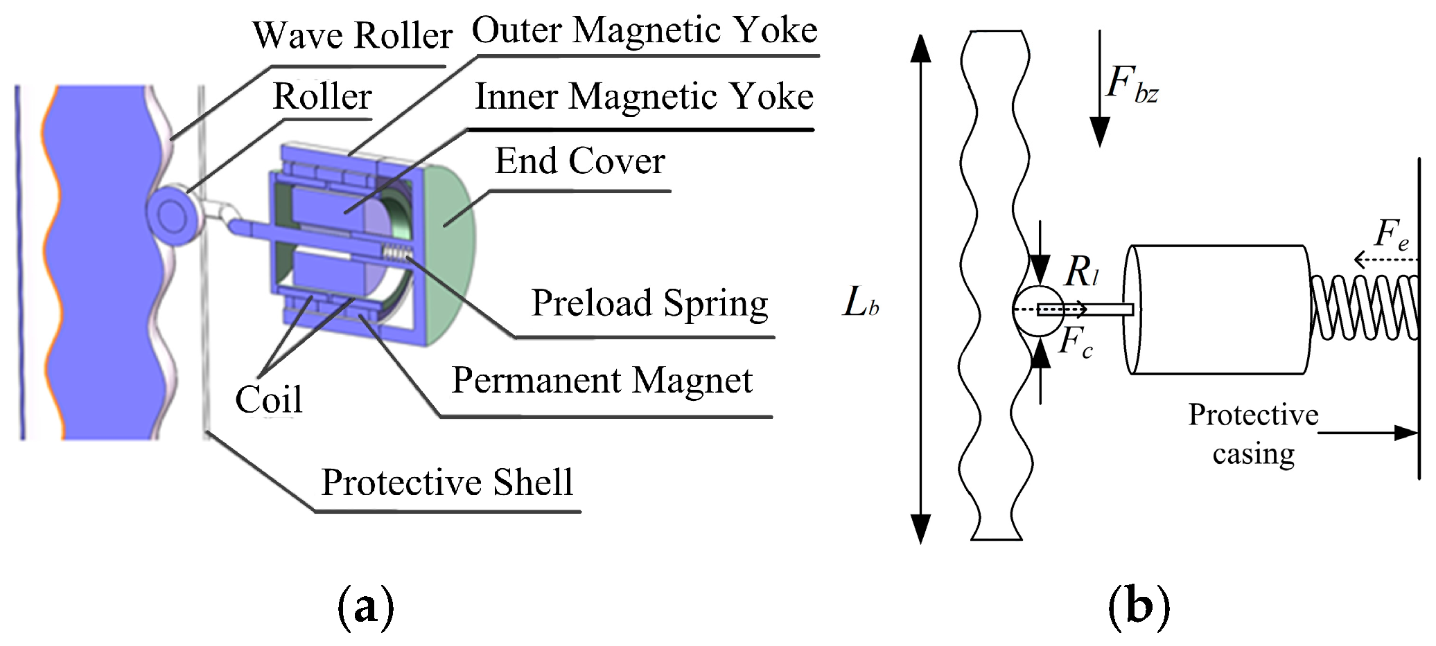
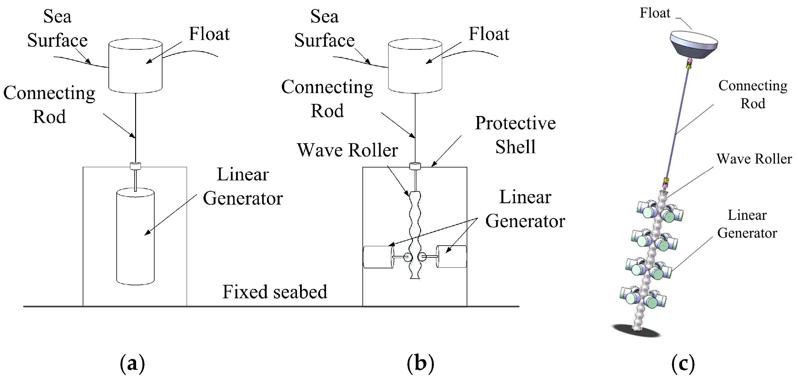
2. Design of a Novel Wave-Roller-Based Driving Mechanical Interface

Currently, most floating wave energy conversion devices utilize the oscillating buoy method, where wave-induced vertical oscillations of the buoy directly drive a linear generator or a mechanical structure to power a rotary generator. While this method offers advantages such as structural simplicity, it also has inherent drawbacks, including short stroke lengths, low oscillation frequencies, significant energy loss during operation, and low electromechanical conversion efficiency [21].
In this paper, a new type of floating wave energy converter is proposed, based on a moving-coil linear generator, incorporating a wave rolling conversion mechanism. This device converts the vertical wave energy captured by the buoy into horizontal mechanical energy with a fixed amplitude, which is then directly transferred to the linear generator. The operating principle of the new linear generator cross-section is illustrated in Figure 1.
The comparison between the classical linear generation system and the new linear generation system is shown in Figure 2.
Figure 2b illustrates the schematic of the new wave energy conversion device. When the buoy captures wave energy, it drives the wave roller, which is connected via a linkage, to move vertically in a reciprocating motion. Since the generator and its protective casing (corrosion-resistant materials are employed) are fixed together and anchored in the seawater, the vertical movement of the wave roller forces the generator’s mover to reciprocate horizontally along the surface of the wave roller. The advantages of adding the wave-rolling mechanism are evident: it stabilizes the linear generator’s stroke using a mechanical structure, converting the wave’s dual-random characteristics of amplitude and frequency into a single-random frequency, facilitating further research on the power generation system. Compared to classical systems where the floater is directly connected to the generator, this system prevents material waste in the design of the mover or stator due to large strokes, thereby improving the efficiency of wave energy utilization by expanding the range of wave amplitude usage.
The design’s working principle is that the floater moves up and down with waves, capturing wave energy. Through the wave roller mechanism, the floater’s low-frequency, large-stroke motion is converted into the mover’s high-frequency, small-stroke motion. The mover then drives the linear generator to produce irregular AC power. Assuming the wave-roller-converted waveform acting on the roller is x(t), the voltage equilibrium equation is given by the following [22]:
i r + L d i d t + E = U E = k i d x ( t ) d t
In the formula, r is the stator winding resistance; L is the stator winding inductance; i is the stator current; E is the motion-induced voltage drop caused by mechanical movement; U is the stator terminal voltage; and ki is the electromagnetic force coefficient of the motor.
Additionally, theoretically, when the force captured by the buoy is sufficient, the wave roller mechanism can drive multiple linear generators simultaneously, maximizing the use of wave energy, as shown in Figure 2c.
In summary, the novel linear power generation system with a wave roller offers the following advantages: The wave roller mechanism significantly shortens the stroke of the linear generator mover, reducing both the generator size and cost. The mover’s trajectory is transformed from low-frequency, large-stroke random motion into high-frequency, fixed-stroke motion, converting its characteristics from dual randomness in amplitude and frequency to single randomness in frequency, facilitating further research on the power generation system. Theoretically, the wave roller can simultaneously drive multiple linear generators, enhancing the energy utilization efficiency per floater.

3. Tuning of Key Parameters in the Novel Moving-Coil Wave Power Generation Device

The novel moving-coil wave power generation device with a wave roller offers significant advantages over classical power generation devices. To ensure it operates in an optimal state, this section will focus on tuning the key parameters of the device. The objective is to minimize losses, and three optimal targets are derived. The optimal tuning parameters are then obtained using MATLAB’s Optimization Toolbox.
Assuming the surface of the wave roller device has a sinusoidal shape, the surface shape equation is given by
y ( x ) = A sin 2 π λ x
In the equation, A represents the amplitude of the wave roller surface waveform, and λ denotes the wavelength of the waveform on the wave roller surface.
The function x(t) describes the vertical reciprocating motion of the floater with the waves (with the power generation device fixed and the motor and floater connected by a linkage; for simplicity, only the vertical reciprocating motion of the floater is considered).
At this point, the wave captured by the floater, and subsequently converted by the wave roller, results in the motion trajectory of the generator’s rotor being given by
y ( t ) = A sin 2 π λ x ( t )
In the equation, x(t) is obtained from the previously mentioned wave model.
Since the wave roller and rotor are two curved surfaces, the composite curvature is calculated for subsequent analysis.
From the radius of curvature formula
R = 1 K = 1 + y 2 3 2 y
The curvature radius Rs of the wave roller surface can be obtained as follows:
R s = 1 + A 2 π λ cos 2 π λ x 2 3 2 A 2 π λ 2 sin 2 π λ x
Assuming the radius of the rotor wheel is Rw, the composite curvature radius Reff is as follows:
R e f f = R s R w R s + R w
Since Rs varies, Reff also varies.
Next, we analyze the forces acting on the wave roller and the rotor wheel shown in Figure 1b.
The generator and the device housing are integrated into a single unit, fixed in the water. The wave roller is connected to the buoy and moves up and down with the waves within the wave roller’s stroke. In the vertical direction, the combined effect of the wave roller’s weight and the buoy’s captured buoyancy varies dynamically, resulting in motion. Horizontally, the wave roller experiences a spring force exerted by the pre-tensioned spring inside the generator onto the roller. For analysis purposes, the roller is taken as the object of study.
To minimize frictional losses at the contact surfaces, our primary goal is to keep the normal force as low as possible.
min F N = F e cos θ + F c F e = k s F c = m v / cos θ 2 R e f f θ = arctan A 2 π λ cos 2 π λ x
In the formula, FN is the normal force; the spring elastic force Fe and the centrifugal force Fc generated by the roller moving on the curved surface are shown in Figure 1b; k is the spring stiffness coefficient; s is the spring compression length; m is the wave roller mass; v is the wave roller’s reciprocating motion speed, which varies and can be obtained by differentiating the motion equation after limiting the wave roller’s travel; θ is the angle between the contact surface tangent and the vertical plane.
Due to the curvature of the wave roller surface, centrifugal force is generated as the roller moves along the wave roller’s surface due to its velocity and curvature. To ensure optimal performance of the wave roller and roller system, in addition to minimizing the normal force (Objective 1), we must also ensure that the roller does not detach at the wave roller’s peak (which is approximated as the peak for simplicity in calculations). Thus, Objective 2 is to ensure that at the wave roller’s peak, the spring force exceeds the centrifugal force, i.e.,
k s w m v / cos θ 2 R e f f
In the equation, sw represents the spring compression length at the wave peak.
Finally, to ensure that the roller maintains full contact with the wave roller at the wave trough, the wavelength λ must satisfy certain conditions.
From Equation (5), the local curvature at the wave roller’s trough position is given by
R s t = 1 + A 2 π λ cos 2 π λ x 2 3 2 A 2 π λ 2 sin 2 π λ x = 1 + 0 2 3 2 A 2 π λ 2 1 = 1 A 2 π λ 2 = λ 2 4 π 2 A
In the formula, Rst represents the local curvature.
To ensure the roller maintains full contact with the wave roller at the trough, the curvature of the roller must be greater than or equal to the curvature at the trough, i.e., the roller’s radius of curvature must be less than or equal to the radius of curvature at the trough.
R w λ 2 4 π 2 A
This leads to the relationship between the wavelength and amplitude of the wave roller and the radius of curvature, which constitutes our Objective 3.
λ > 2 π A R w
In summary, to ensure the wave roller and rotor operate under optimal conditions with minimal losses, three objectives were derived. By inputting these objective constraints and known parameters into MATLAB’s Optimization Toolbox, the optimal solution for the target parameters can be obtained, completing the parameter tuning process.

4. Simulation Analysis

Based on the modeling and analysis of each component discussed earlier, this section uses MATLAB/Simulink to build a simulation model and perform a simulation analysis of the newly designed moving-coil linear generator with a wave roller, to verify the feasibility of the designed generator. Theoretically, the device can power multiple linear generators simultaneously; however, for simplicity, the simulation is conducted with only one linear generator driven by the wave roller. The known parameters of the power generation device are listed in Table 1. The simulation process is shown in Figure 3.

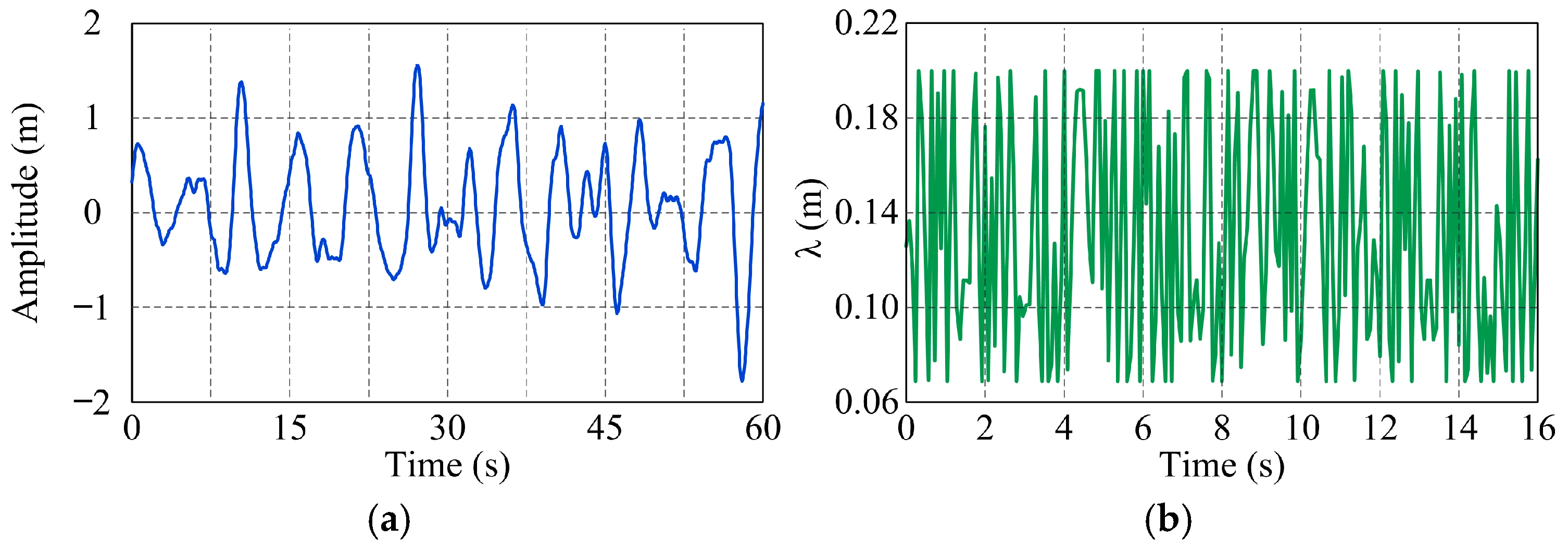
4.1. Determination of Optimal Wavelength for the Wave Roller

Based on the data from reference [23], as shown in Table 2, the significant wave height at Beishuang Island ranged from 0 to 1.2 m with a probability of 93.08% during the observation period, while the wave period ranged from 3 to 6 s with a probability of 94.27%. A wave model is established using the JONSWAP spectrum [24], as shown in Figure 4a. Subsequently, based on the wave model, the analysis in Section 3, and the data in Table 1, an optimization model is established using MATLAB’s Optimization Toolbox. The remaining parameters to be determined are the wave rolling amplitude A and the wave rolling wavelength λ. According to Table 1, the generator rotor stroke is ±15 mm, making A = 15 mm the most appropriate choice. Therefore, only λ needs to be determined, which is constrained to be less than 0.2 m for practical considerations. The final optimized parameters are shown in Figure 4b.
As shown in Figure 4b, the optimal parameters vary at different times. For this multi-modal problem, an average value approach is used to obtain the optimal solution. This method provides an overall optimization while simplifying the solution process. Ultimately, the optimal wavelength λ for the wave roller is determined to be 0.12 m, which will be used in the subsequent simulations.

4.2. Simulation of the Entire New Power Generation Device

This section focuses on the simulation of the entire new power generation device. First, a visual simulation is conducted, covering the entire process from the floater capturing wave energy to the wave roller’s motion range limitations and the wave roller’s conversion process. This provides an intuitive understanding of the energy form after mechanical conversion. Next, the simulation of the power generation part is performed to verify the usability of the electrical energy after processing.

4.2.1. Simulation of the Wave Roller Structure

The wave waveform captured by the floater and the waveform of the wave roller after motion range limitations are shown in Figure 5a. The waveform after the wave roller’s structural conversion is depicted in Figure 5b.
From Figure 5, it can be observed that after the wave roller structure conversion, the low-frequency, large-stroke waveform of the wave has been successfully converted into a high-frequency, small-stroke waveform. This conversion significantly shortens the linear generator’s mover stroke, reducing the generator’s size and cost while enhancing wave energy utilization. In contrast, classical systems, where the buoy is directly connected to the linear generator, are largely limited by the mover’s stroke in harnessing wave amplitude. Additionally, the mover’s magnetic flux cutting path can be transformed from dual-random characteristics in amplitude and frequency to a single-random characteristic in frequency, simplifying future research on control strategies for the power generation system.

4.2.2. Power Absorption Rate of the New Power Generation Device

In this section, simulations are conducted for both the classical and the new power generation devices, and their power generation outputs are compared. Simulations are performed under the condition where both devices supply power directly to a 10 Ω resistive load. This approach aims to minimize the influence of other factors on power output. The average power is then calculated using Equation (12).
p ( t ) = v ( t ) i ( t ) P a v g = 1 T o T p t d t
In the formula, p(t) is the instantaneous power, v(t) is the instantaneous voltage, and i(t) is the instantaneous current. pavg is the average power.
The voltage and current waveforms of the new power generation device are shown in Figure 6.
The average power is calculated to be 143.4 W. Theoretically, the wave rolling device can operate at least six such linear generators, resulting in a total power of PR = 860.4 W.
Next, the power absorption rate is calculated according to the formula in [25].
η r a t = P R Δ k T e H s 2 100 % k = ρ g 2 64 π
In the formula, ηrat is the power absorption rate of the generation device; PR is the generator output power; Δ is the system parameter, set to 0.2 [26]; k is the wave number; Te is the wave energy period; Hs is the significant wave height; ρ = 1030 kg/m3 (approximate seawater density); g = 9.8 m/s2 (gravitational acceleration). Using the wave data from [26] and substituting them into Equation (13), the calculation can be performed.
η r a t = 860.4 3775.49 100 % 23 %
From the above calculation, it can be seen that compared to the maximum power absorption rate of 20% for classical standalone generation devices [25], the new generation device has a higher power absorption rate. However, the current calculated power absorption rate is still conservative, as the linear generators used are relatively small. When the buoyancy of the floater is sufficient, the device can drive more generators. This can further lead to a higher power absorption rate.

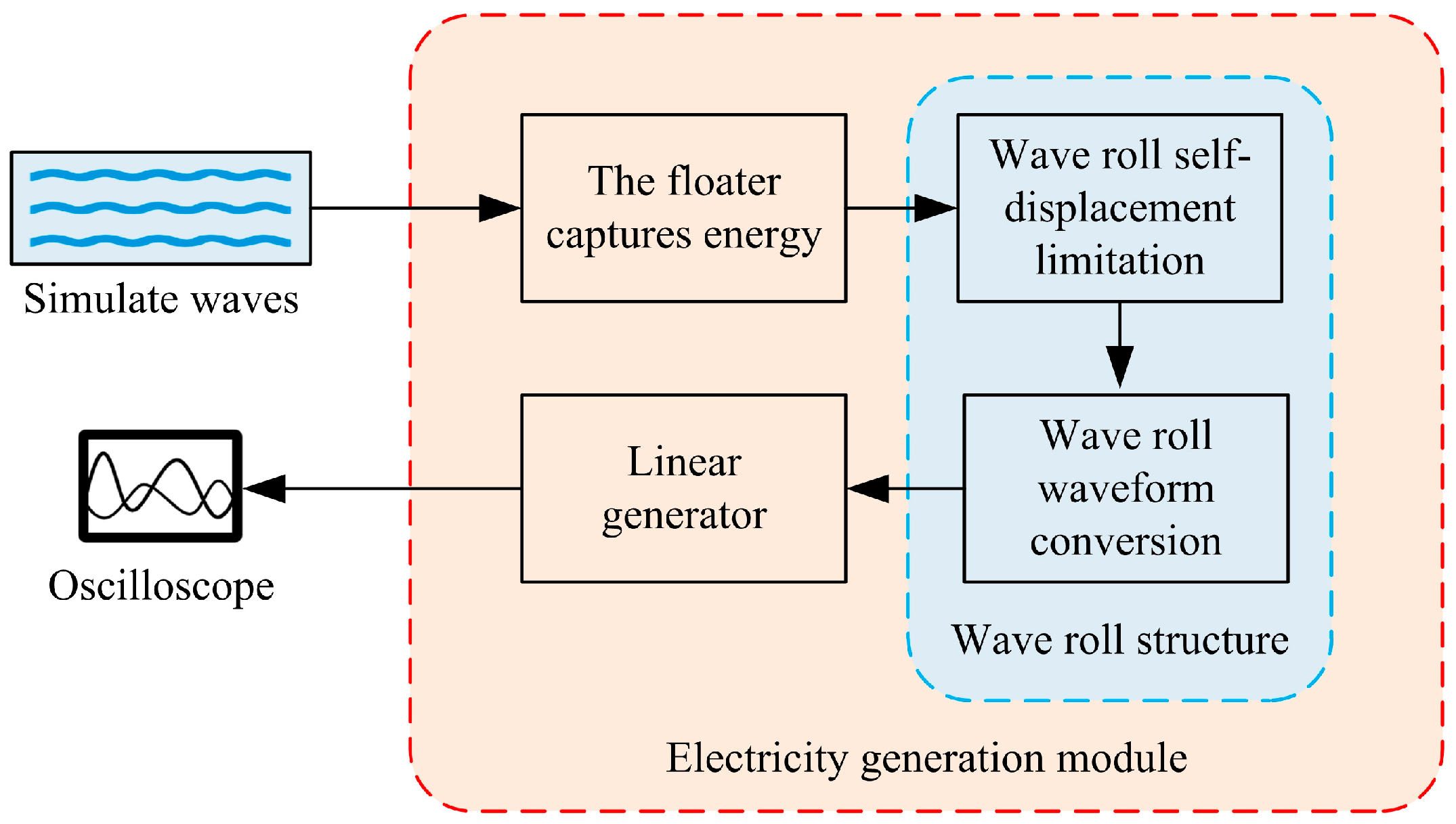
5. Experimental Results

Based on the above analysis and considering practical factors, a new experimental platform for the generator device is designed. The platform is illustrated in Figure 7.
The linear power generation system test platform consists of a crank-slider mechanism, a variable-speed motor, a linear generator, a generator mounting frame, a copper wave roller, and a central shaft. The entire system is installed and fixed on the generator mounting frame. The variable-speed motor drives the linkage mechanism to generate a simulated wave profile, which, constrained by two sliding bearings, drives the motion of the wave roller. Under the fixation of the central shaft and the combined action of the generator-like device and the roller of the linear generator, the wave roller moves vertically. The roller drives the reciprocating motion of the linear generator mover, cutting magnetic flux lines to generate electricity. The variable-speed motor in the test bench, which simulates wave motion, has a torque of 13 N·m and a power of 120 W. The speed controller used is the US-52 model. The parameters of the wave roller and generator are consistent with those in the simulation section. The experimental platform uses the previously established wave model as input for testing. The waveforms obtained from simulation and measurement are shown in Figure 8, where the oscilloscope waveform represents a locally magnified section corresponding to the relevant portion of the simulation waveform.
From Figure 8, it can be observed that the voltage waveforms obtained through simulation and those measured by the oscilloscope exhibit the following similarities. The voltage amplitude ranges of both waveforms are comparable. Both exhibit interruptions, where the voltage significantly drops to near zero. The frequency characteristics are similar, with high-frequency oscillations on both sides and a relatively smooth interval in the middle. This preliminarily verifies the feasibility of the designed generator device. Although the experimental conditions are relatively simple, the results provide a foundation for validation under more complex working conditions and offer important reference data for further performance optimization.

6. Conclusions

Theoretical analysis and experiments indicate that the newly designed power generation device significantly reduces the stroke of the linear generator rotor by integrating a wave roller mechanism into the conventional floating linear generator. This design enhances output power while reducing the required generator size. The device successfully transforms the rotor motion from low-frequency, large-stroke movement into high-frequency, small-stroke movement. This transformation shifts the electrical waveform characteristics from dual-random variations in amplitude and frequency to a single-random frequency characteristic, facilitating future research on power generation systems. Theoretically, the wave roller mechanism can drive multiple linear generators simultaneously, improving the energy utilization efficiency of each floater. Finally, an experimental platform was constructed for preliminary validation. However, further research is needed, particularly in developing a more suitable current control system to enhance overall performance.

Author Contributions

Conceptualization, H.C. and N.L.; methodology, N.L.; software, N.L.; validation, H.C.; formal analysis, X.L.; investigation, X.L.; writing—original draft preparation, N.L.; writing—review and editing, N.L.; visualization, N.L.; supervision, H.C.; funding acquisition, H.C. All authors have read and agreed to the published version of the manuscript.

Funding

This work is supported by National Natural Science Foundation of China (Award No. 52474173; No. 52174115; No. 51874157). Basic Research Project of Liaoning Provincial Department of Education (LJ212410147021).

Data Availability Statement

Data are contained with the article.

Conflicts of Interest

Author Naisheng Liu was employed by the company State Grid Fuxin Electric Power Supply Company. The remaining authors declare that the research was conducted in the absence of any commercial or financial relationships that could be construed as a potential conflict of interest.

References

  1. Hu, C.; Mao, H.Y.; You, Z.J.; Shi, H.Y.; Gao, S. Study on the distribution of wave energy resources in China and the applicability of wave energy generation device. Mar. Sci. 2018, 42, 142–148. [Google Scholar]
  2. Liu, W.M.; Ma, C.L.; Chen, F.Y.; Liu, L.; Ge, Y.Z.; Peng, J.P.; Wu, H.Y.; Wang, Q.B. Exploitation and Technical Progress of Marine Renewable Energy. Adv. Mar. Sci. 2018, 36, 1–18. [Google Scholar]
  3. Liu, Y.X.; Wang, H.F.; Wang, J.; Chen, L.B. Reflections on the exploitation and utilization of marine renewable energy under the background of ocean power. Sci. Technol. Rev. 2018, 36, 22–25. [Google Scholar]
  4. Li, J.L.; Shen, M.H.; Ma, R.F.; Yang, H.S.; Chen, Y.N. Marine resource economy and strategy under the background of marine ecological civilization construction. J. Nat. Resour. 2022, 37, 829–849. [Google Scholar] [CrossRef]
  5. Yin, Y.B. Principle and Device of the Ocean Wave Energy Conversion; Shanghai Scientific & Technical Publishers: Shanghai, China, 2013. [Google Scholar]
  6. Bruschi, D.; Fernandes, J.; Falcão, A.; Bergmann, C. Analysis of the degradation in the Wells turbine blades of the Pico oscillating-water-column wave energy plant. Renew. Sustain. Energy Rev. 2019, 115, 109368. [Google Scholar] [CrossRef]
  7. Doyle, S.; Aggidis, G.A. Development of multi-oscillating water columns as wave energy converters. Renew. Sustain. Energy Rev. 2019, 107, 75–86. [Google Scholar] [CrossRef]
  8. Gong, Y.H. Overall design and optimization of dish overtopping wave energy generation system. Ship Sci. Technol. 2017, 39, 58–60. [Google Scholar]
  9. Renzi, E.; Doherty, K.; Henry, A.; Dias, F. How does Oyster work? The simple interpretation of Oyster mathematics. Eur. J. Mech. B Fluids 2014, 47, 124–131. [Google Scholar] [CrossRef]
  10. Zhang, Y.Q.; Sheng, S.W.; You, Y.G.; Wang, S.L.; Wang, Z.; Peng. Development Status and Application Direction of Wave Energy Generation Technology. Adv. New Renew. Energy 2019, 7, 374–378. [Google Scholar]
  11. Zhang, H.; Zhou, B.; Vogel, C.; Willden, R.; Zang, J.; Zhang, L. Hydrodynamic performance of a floating breakwater as an oscillating-buoy type wave energy converter. Appl. Energy 2020, 257, 113996. [Google Scholar] [CrossRef]
  12. Soares, J.B.; Monteiro-Neto, C.; da Costa, M.R.; Martins, R.R.M.; dos Santos Vieira, F.C.; de Andrade-Tubino, M.F.; Bastos, A.L.; de Almeida Tubino, R. Size structure, reproduction, and growth of skipjack tuna (Katsuwonus pelamis) caught by the pole-and-line fleet in the southwest Atlantic. Fish. Res. 2019, 212, 136–145. [Google Scholar] [CrossRef]
  13. Wu, J.; Yao, Y.; Zhou, L.; Göteman, M. Real-time latching control strategies for the solo Duck wave energy converter in irregular waves. Appl. Energy 2018, 222, 717–728. [Google Scholar] [CrossRef]
  14. Henderson, R. Design, simulation, and testing of a novel hydraulic power take-off system for the Pelamis wave energy converter. Renew. Energy 2006, 31, 271–283. [Google Scholar] [CrossRef]
  15. Palha, A.; Mendes, L.; Fortes, C.J.; Brito-Melo, A.; Sarmento, A. The impact of wave energy farms in the shoreline wave climate: Portuguese pilot zone case study using Pelamis energy wave devices. Renew. Energy 2010, 35, 62–77. [Google Scholar] [CrossRef]
  16. Sheng, S.W.; Zhang, Y.Q.; Wang, S.L.; Wang, Z.P.; Lin, H.J.; Ye, Y. Research on Wave Energy Converter Sharp Eagle 1. Nav. Archit. Mar. Eng. Eng. 2015, 37, 104–108. [Google Scholar]
  17. Sheng, S.W.; Wang, S.L.; Lin, H.J.; Zhang, Y.Q.; You, Y.G.; Wang, Z.P. Open sea tests of 100 kw wave energy convertorsharp eagle wanshan. Acta Energiae Solaris Sin. 2019, 40, 709–714. [Google Scholar]
  18. Zhao, B.; Dong, S.L.; Li, Z.H.; Zhang, B.C. Multi-physics coupling modeling method for the rolling-spherical triboelectric nanogenerator. Tribology 2020, 40, 680–686. [Google Scholar]
  19. Wu, C.; Wang, A.C.; Ding, W.; Guo, H.; Wang, Z.L. Triboelectric nanogenerator: A foundation of the energy for the new era. Adv. Energy Mater. 2019, 9, 1802906. [Google Scholar] [CrossRef]
  20. Xu, C.; Liu, Z.; Tang, G. Experimental study of the hydrodynamic performance of a U-oscillating water column wave energy converter. Ocean. Eng. 2022, 265, 112598. [Google Scholar] [CrossRef]
  21. Xiao, X.; Bai, N.Z.; Kang, Q.; Nie, Z.X.; Huang, X.R. A Review of the Development of Wave Power System and the Research on Direct-Drive Wave Power System. Trans. China Electrotech. Soc. 2014, 29, 1–11. [Google Scholar]
  22. Wang, Y. Research on Single-Phase Oscillating Permanent Magnet Linear Generator; Harbin Institute of Technology: Harbin, China, 2014. [Google Scholar]
  23. Huang, Q.Z.; Song, W.; Wang, Q.Y.; Chen, X.L.; Wang, H.; Chen, B.Q. The wave height and period distribution characteristics around Bei Shuang Island in summer. Mar. Forecast. 2021, 38, 52–58. [Google Scholar]
  24. Guo, Q.; Xu, Z. Simulation of deep-water waves based on JONSWAP spectrum and realization by MATLAB. In Proceedings of the 2011 19th International Conference on Geoinformatics, Shanghai, China, 24–26 June 2011; pp. 1–4. [Google Scholar]
  25. Engström, J.; Kurupath, V.; Isberg, J.; Leijon, M. A resonant two body system for a point absorbing wave energy converter with direct-driven linear generator. J. Appl. Phys. 2011, 110, 124904. [Google Scholar] [CrossRef]
  26. Yin, B.T. Study on Hydrodynamics of Oscillating Float-Type Wave Energy Extractor; Zhejiang Ocean University: Zhoushan, China, 2021. [Google Scholar]
Figure 1. Cross-sectional diagrams: (a) Three-dimensional cross-sectional diagram; (b) Planar cross-sectional diagram.
Actuators 14 00147 g001
Figure 2. Structural comparison of (a) classic and (b) our proposed power generation systems, and (c) suggested simultaneous operation of multiple linear generators.
Actuators 14 00147 g002
Figure 3. Simulation process diagram.
Actuators 14 00147 g003
Figure 4. (a) Wave model diagram; (b) optimized solution of λ.
Actuators 14 00147 g004
Figure 5. (a) Displacement waveform of the floater and wave roller; (b) displacement waveform of the mover after conversion by the wave roller.
Actuators 14 00147 g005
Figure 6. Voltage and current waveform diagram of the new power generation system.
Actuators 14 00147 g006
Figure 7. New generator device experimental platform.
Actuators 14 00147 g007
Figure 8. Simulation and Experimental Voltage Waveforms.
Actuators 14 00147 g008
Table 1. Relevant parameters.
Parameter NameSymbolValue
Spring constant/(N/mm)k5.4
Coil resistance/ΩRc20.9
Number of coil turns/Turns-640
Enameled wire diameter/mmdc0.5
Mover stroke/mmXm±15.0
Wave roller length/mLb1.2
Wave roller stroke/mXw±1.2
Roller radius/mmRw8
Roller mass/kgmr0.05
Table 2. Frequency of significant wave height and average period occurrence (Unit: %).
MonthSignificant Wave Height Range/mAverage Period/s
<0.50.5~1.21.2~2.5>2.50~33~44~55~6>6
68.0823.381.160013.3516.952.300.02
714.9515.862.710.25016.5413.083.660.48
87.4623.362.80002.4314.9910.965.23
Overall30.4862.606.670.25032.3245.0216.925.73
Disclaimer/Publisher’s Note: The statements, opinions and data contained in all publications are solely those of the individual author(s) and contributor(s) and not of MDPI and/or the editor(s). MDPI and/or the editor(s) disclaim responsibility for any injury to people or property resulting from any ideas, methods, instructions or products referred to in the content.

